- New and Changed Information
- Preface
- Overview
- Configuring CDP
- Configuring the Domain
- Managing Server Connections
- Managing the Configuration
- Working with Files
- Managing Users
- Configuring NTP
- Configuring Local SPAN and ERSPAN
- Configuring SNMP
- Configuring NetFlow
- Configuring System Message Logging
- Configuring iSCSI Multipath
- Configuring VSM Backup and Recovery
- Virtualized Workload Mobility (DC to DC vMotion)
- Configuration Limits
- Index
Cisco Nexus 1000V System Management Configuration Guide, Release 4.2(1)SV1(4b)
Bias-Free Language
The documentation set for this product strives to use bias-free language. For the purposes of this documentation set, bias-free is defined as language that does not imply discrimination based on age, disability, gender, racial identity, ethnic identity, sexual orientation, socioeconomic status, and intersectionality. Exceptions may be present in the documentation due to language that is hardcoded in the user interfaces of the product software, language used based on RFP documentation, or language that is used by a referenced third-party product. Learn more about how Cisco is using Inclusive Language.
- Updated:
- May 20, 2013
Chapter: Configuring the Domain
Configuring the Domain
This chapter describes how to configure the Cisco Nexus 1000V domain, including creating the domain, assigning VLANs, configuring Layer 3 Control, and so forth.
This chapter includes the following topics:
•![]() Feature History for the VSM Domain
Feature History for the VSM Domain
Information About the Domain
You must create a domain name for Cisco Nexus 1000V and then add control and packet VLANs for communication and management. This process is part of the initial setup of the a Cisco Nexus 1000V when installing the software. If you need to create a domain later, you can do so using the setup command or the procedures described in this chapter.
About Layer 3 Control
Layer 3 control, or IP connectivity, is supported between the VSM and VEM for control and packet traffic. With Layer 3 control, a VSM can be Layer 3 accessible and control hosts that reside in a separate Layer 2 network. All hosts controlled by a VSM, however, must still reside in the same Layer 2 network. Since a VSM cannot control a host that is outside of the Layer 2 network it controls, the host on which it resides must be controlled by another VSM.
To implement Layer 3 control, you must make the following configurations:
•![]() Configure the VSM domain transport mode as Layer 3.
Configure the VSM domain transport mode as Layer 3.
For more information, see the "Changing to Layer 3 Transport" procedure
•![]() Configure a port profile using the "Creating a Port Profile for Layer 3 Control" procedure.
Configure a port profile using the "Creating a Port Profile for Layer 3 Control" procedure.
•![]() Create an VMware kernel NIC interface on each host and apply the Layer 3 control port profile to it. For more information, see your VMware documentation.
Create an VMware kernel NIC interface on each host and apply the Layer 3 control port profile to it. For more information, see your VMware documentation.
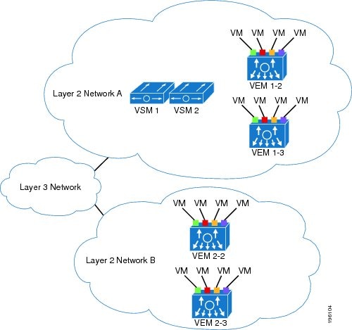
Figure 3-1 illustrates the following example of Layer 3 control.
•![]() VSM0 controls VEM_0_1.
VSM0 controls VEM_0_1.
•![]() VEM_0_1, in turn, hosts VSM1 and VSM2.
VEM_0_1, in turn, hosts VSM1 and VSM2.
•![]() VSM1 and VSM2 control VEMs in other Layer 2 networks.
VSM1 and VSM2 control VEMs in other Layer 2 networks.
Figure 3-1 Example of Layer 3 Control IP Connectivity
Guidelines and Limitations
The VSM domain has the following configuration guidelines and limitations:
•![]() UDP port 4785 is required for Layer 3 communication between the VSM and VEM. If you have a firewall in your network, and are configuring Layer 3 control, then make sure UDP port 4785 is open on your upstream switch or firewall device. For more information, see the documentation for your upstream switch or firewall device.
UDP port 4785 is required for Layer 3 communication between the VSM and VEM. If you have a firewall in your network, and are configuring Layer 3 control, then make sure UDP port 4785 is open on your upstream switch or firewall device. For more information, see the documentation for your upstream switch or firewall device.
•![]() In a Layer 2 network, you can switch between the Layer 2 and Layer 3 transport modes, but when you do so, the modules may be out of service briefly.
In a Layer 2 network, you can switch between the Layer 2 and Layer 3 transport modes, but when you do so, the modules may be out of service briefly.
•![]() The capability attribute (Layer 3 control) cannot be inherited from the port profile.
The capability attribute (Layer 3 control) cannot be inherited from the port profile.
•![]() Different hosts can use different VLANs for Layer 3 control.
Different hosts can use different VLANs for Layer 3 control.
•![]() A port profile used for Layer 3 control must be an access port profile. It cannot be a trunk port profile.
A port profile used for Layer 3 control must be an access port profile. It cannot be a trunk port profile.
•![]() We recommend that if you are using the VMware kernel NIC for Layer 3 Control, you do not use it for any other purpose. For example, do not also use the Layer 3 Control VMware kernel NIC for VMotion or NFS mount.
We recommend that if you are using the VMware kernel NIC for Layer 3 Control, you do not use it for any other purpose. For example, do not also use the Layer 3 Control VMware kernel NIC for VMotion or NFS mount.
•![]() Control VLANs, packet VLANs, and management VLANs must be configured as regular VLANs and not as private VLANs.
Control VLANs, packet VLANs, and management VLANs must be configured as regular VLANs and not as private VLANs.
•![]() If you have a firewall in your network, ensure that TCP ports 80 and 443 are open for traffic destined to the vCenter Server and TCP port 80 is open for traffic destined to the Cisco Nexus 1000V Virtual Supervisor Module (VSM).
If you have a firewall in your network, ensure that TCP ports 80 and 443 are open for traffic destined to the vCenter Server and TCP port 80 is open for traffic destined to the Cisco Nexus 1000V Virtual Supervisor Module (VSM).
Default Settings
Table 3-1 lists the default settings in the domain configuration.
Configuring the Domain
This section includes the following procedures:
•![]() Changing to Layer 3 Transport
Changing to Layer 3 Transport
•![]() Changing to Layer 2 Transport
Changing to Layer 2 Transport
•![]() Creating a Port Profile for Layer 3 Control
Creating a Port Profile for Layer 3 Control
Creating a Domain
Use this procedure to create a domain name for the Cisco Nexus 1000V that identifies the VSM and VEMs; and then add control and packet VLANs for communication and management. This process is part of the initial setup of the Cisco Nexus 1000V when installing the software. If you need to create a domain after initial setup, you can do so using this procedure.
BEFORE YOU BEGIN
Before beginning this procedure, you must know or do the following:
•![]() If two or more VSMs share the same control and/or packet VLAN, the domain helps identify the VEMs managed by each VSM.
If two or more VSMs share the same control and/or packet VLAN, the domain helps identify the VEMs managed by each VSM.
•![]() You are logged in to the CLI in EXEC mode.
You are logged in to the CLI in EXEC mode.
•![]() You must have a unique domain ID for this Cisco Nexus 1000V instance.
You must have a unique domain ID for this Cisco Nexus 1000V instance.
•![]() You must identify the VLANs to be used for control and packet traffic.
You must identify the VLANs to be used for control and packet traffic.
•![]() We recommend using one VLAN for control traffic and a different VLAN for packet traffic.
We recommend using one VLAN for control traffic and a different VLAN for packet traffic.
•![]() We recommend using a distinct VLAN for each instances of Cisco Nexus 1000V (different domains)
We recommend using a distinct VLAN for each instances of Cisco Nexus 1000V (different domains)
•![]() The svs mode command in the SVS Domain Configuration mode is not used and has no effect on a configuration.
The svs mode command in the SVS Domain Configuration mode is not used and has no effect on a configuration.
•![]() For information about changing a domain ID after adding a second VSM see the Cisco Nexus 1000V High Availability and Redundancy Configuration Guide, Release 4.2(1)SV1(4b).
For information about changing a domain ID after adding a second VSM see the Cisco Nexus 1000V High Availability and Redundancy Configuration Guide, Release 4.2(1)SV1(4b).
SUMMARY STEPS
1. ![]() config t
config t
2. ![]() svs-domain
svs-domain
3. ![]() domain id domain-id
domain id domain-id
4. ![]() control vlan vlan-id
control vlan vlan-id
5. ![]() packet vlan vlan-id
packet vlan vlan-id
6. ![]() exit
exit
7. ![]() show svs domain
show svs domain
8. ![]() copy running-config startup-config
copy running-config startup-config
DETAILED STEPS
Example:
n1000v# config t
n1000v(config)# svs-domain
n1000v(config-svs-domain)# domain id 100
n1000v(config-svs-domain)# control vlan 190
n1000v(config-svs-domain)# packet vlan 191
n1000v(config-vlan)# exit
n1000v (config)# show svs domain
SVS domain config:
Domain id: 100
Control vlan: 190
Packet vlan: 191
L2/L3 Aipc mode: L2
L2/L3 Aipc interface: mgmt0
Status: Config push to VC successful.
n1000v(config)#
n1000v(config)# copy run start
[########################################] 100%
n1000v(config)#
Changing to Layer 3 Transport
Use this procedure to change the transport mode from Layer 2 to Layer 3 for the VSM domain control and packet traffic.
BEFORE YOU BEGIN
Before beginning this procedure, you must know or do the following:
•![]() You are logged in to the CLI in EXEC mode.
You are logged in to the CLI in EXEC mode.
•![]() This procedure requires you to disable the control and packet VLANs. You cannot change to Layer 3 Control before disabling the control and packet VLANs.
This procedure requires you to disable the control and packet VLANs. You cannot change to Layer 3 Control before disabling the control and packet VLANs.
•![]() You have already configured the Layer 3 interface (mgmt 0 or control 0) and assigned an IP address.
You have already configured the Layer 3 interface (mgmt 0 or control 0) and assigned an IP address.
•![]() When control 0 is used for Layer 3 transport, proxy-arp must be enabled on the control 0 VLAN gateway router.
When control 0 is used for Layer 3 transport, proxy-arp must be enabled on the control 0 VLAN gateway router.
For information about configuring an interface, see the Cisco Nexus 1000V Interface Configuration Guide, Release 4.2(1)SV1(4a).
SUMMARY STEPS
1. ![]() show svs domain
show svs domain
2. ![]() config t
config t
3. ![]() svs-domain
svs-domain
4. ![]() no control vlan
no control vlan
5. ![]() no packet vlan
no packet vlan
6. ![]() show svs domain
show svs domain
7. ![]() svs mode L2 | svs mode L3 interface { mgmt0 | control0 }
svs mode L2 | svs mode L3 interface { mgmt0 | control0 }
8. ![]() show svs domain
show svs domain
9. ![]() copy running-config startup-config
copy running-config startup-config
DETAILED STEPS
Changing to Layer 2 Transport
Use this procedure to change the transport mode to Layer 2 for the VSM domain control and packet traffic. The transport mode is Layer 2 by default, but if it is changed, you can use this procedure to configure it again as Layer 2.
BEFORE YOU BEGIN
Before beginning this procedure, you must know or do the following:
•![]() You are logged in to the CLI in EXEC mode.
You are logged in to the CLI in EXEC mode.
•![]() This procedure requires you to configure a control VLAN and a packet VLAN. You cannot configure these VLANs if the VSM domain capability is Layer 3 Control. You will first change the capability to Layer 3 Control, and then configure the control VLAN and packet VLAN.
This procedure requires you to configure a control VLAN and a packet VLAN. You cannot configure these VLANs if the VSM domain capability is Layer 3 Control. You will first change the capability to Layer 3 Control, and then configure the control VLAN and packet VLAN.
SUMMARY STEPS
1. ![]() show svs domain
show svs domain
2. ![]() config t
config t
3. ![]() svs-domain
svs-domain
4. ![]() svs mode L2 | svs mode L3 interface { mgmt0 | control0 }
svs mode L2 | svs mode L3 interface { mgmt0 | control0 }
5. ![]() show svs domain
show svs domain
6. ![]() copy running-config startup-config
copy running-config startup-config
DETAILED STEPS
Creating a Port Profile for Layer 3 Control
Use this procedure to allow the VSM and VEM to communicate over IP for control and packet traffic.
BEFORE YOU BEGIN
Before beginning this procedure, you must know or do the following:
•![]() You are logged in to the CLI in EXEC mode.
You are logged in to the CLI in EXEC mode.
•![]() The transport mode for the VSM domain has already been configured as Layer 3. For more information, see the "Changing to Layer 2 Transport" procedure.
The transport mode for the VSM domain has already been configured as Layer 3. For more information, see the "Changing to Layer 2 Transport" procedure.
•![]() All VEMs must belong to the same Layer 2 domain.
All VEMs must belong to the same Layer 2 domain.
•![]() The VEM VM kernel NIC must connect to this Layer 3 control port profile when adding the host to the Cisco Nexus 1000V DVS.
The VEM VM kernel NIC must connect to this Layer 3 control port profile when adding the host to the Cisco Nexus 1000V DVS.
•![]() Only one VM kernel NIC can be assigned to this Layer 3 control port profile per host.
Only one VM kernel NIC can be assigned to this Layer 3 control port profile per host.
•![]() You know the VLAN ID for the VLAN you are adding to this Layer 3 control port profile.
You know the VLAN ID for the VLAN you are adding to this Layer 3 control port profile.
–![]() The VLAN must already be created on the Cisco Nexus 1000V.
The VLAN must already be created on the Cisco Nexus 1000V.
–![]() The VLAN assigned to this Layer 3 control port profile must be a system VLAN.
The VLAN assigned to this Layer 3 control port profile must be a system VLAN.
–![]() One of the uplink ports must already have this VLAN in its system VLAN range.
One of the uplink ports must already have this VLAN in its system VLAN range.
•![]() The port profile must be an access port profile. It cannot be a trunk port profile. This procedure includes steps to configure the port profile as an access port profile.
The port profile must be an access port profile. It cannot be a trunk port profile. This procedure includes steps to configure the port profile as an access port profile.
•![]() More than one port profile can be configured as capability L3 control.
More than one port profile can be configured as capability L3 control.
•![]() Different hosts can use different VLANs for Layer 3 control.
Different hosts can use different VLANs for Layer 3 control.
SUMMARY STEPS
1. ![]() config t
config t
2. ![]() port-profile name
port-profile name
3. ![]() capability l3control
capability l3control
4. ![]() vmware port-group [name]
vmware port-group [name]
5. ![]() switchport mode access
switchport mode access
6. ![]() switchport access vlan vlanID
switchport access vlan vlanID
7. ![]() no shutdown
no shutdown
8. ![]() system vlan vlanID
system vlan vlanID
9. ![]() state enabled
state enabled
10. ![]() (Optional) show port-profile name
(Optional) show port-profile name
11. ![]() (Optional) copy running-config startup-config
(Optional) copy running-config startup-config
DETAILED STEPS
Creating a Control VLAN
Use this procedure to add a control VLAN to the domain.
BEFORE YOU BEGIN
Before beginning this procedure, you must know or do the following:
•![]() You are logged in to the CLI in EXEC mode.
You are logged in to the CLI in EXEC mode.
•![]() If Layer 3 Control is configured on your VSM, you can not create a control VLAN. You must first disable Layer 3 Control.
If Layer 3 Control is configured on your VSM, you can not create a control VLAN. You must first disable Layer 3 Control.
•![]() You have already configured and enabled the required switched virtual interface (SVI) using the document, Cisco Nexus 1000V Interface Configuration Guide, Release 4.2(1)SV1(4a) The SVI is also called the VLAN interface and provides communication between VLANs.
You have already configured and enabled the required switched virtual interface (SVI) using the document, Cisco Nexus 1000V Interface Configuration Guide, Release 4.2(1)SV1(4a) The SVI is also called the VLAN interface and provides communication between VLANs.
•![]() You are familiar with how VLANs are numbered. For more information, see the document,
You are familiar with how VLANs are numbered. For more information, see the document,
Cisco Nexus 1000V Layer 2 Switching Configuration Guide, Release 4.2(1)SV1(4).
•![]() Newly-created VLANs remain unused until Layer 2 ports are assigned to them.
Newly-created VLANs remain unused until Layer 2 ports are assigned to them.
SUMMARY STEPS
1. ![]() config t
config t
2. ![]() vlan vlan-id
vlan vlan-id
3. ![]() name vlan-name
name vlan-name
4. ![]() state vlan-state
state vlan-state
5. ![]() exit
exit
6. ![]() show vlan id vlan-id
show vlan id vlan-id
7. ![]() copy running-config startup-config
copy running-config startup-config
DETAILED STEPS
Example:
n1000v# config t
n1000v(config)# vlan 30
n1000v(config-vlan)# name cp_control
n1000v(config-vlan)# state active
n1000v(config)# show vlan id 30
VLAN Name Status Ports
---- -------------------------------- --------- -------------------------------
30 cp_control active
VLAN Type MTU
---- -----
5 enet 1500
Remote SPAN VLAN
----------------
Disabled
Primary Secondary Type Ports
------- --------- --------------- -------------------------------------------
n1000v(config)# copy run start
[########################################] 100%
n1000v(config)#
Creating a Packet VLAN
Use this procedure to add the packet VLAN to the domain.
BEFORE YOU BEGIN
Before beginning this procedure, you must know or do the following:
•![]() You are logged in to the CLI in EXEC mode.
You are logged in to the CLI in EXEC mode.
•![]() You have already configured and enabled the required switched virtual interface (SVI) using the document, Cisco Nexus 1000V Interface Configuration Guide, Release 4.2(1)SV1(4a). The SVI is also called the VLAN interface and provides communication between VLANs.
You have already configured and enabled the required switched virtual interface (SVI) using the document, Cisco Nexus 1000V Interface Configuration Guide, Release 4.2(1)SV1(4a). The SVI is also called the VLAN interface and provides communication between VLANs.
•![]() You are familiar with how VLANs are numbered. For more information, see the document,
You are familiar with how VLANs are numbered. For more information, see the document,
Cisco Nexus 1000V Layer 2 Switching Configuration Guide, Release 4.2(1)SV1(4).
•![]() Newly-created VLANs remain unused until Layer 2 ports are assigned to them.
Newly-created VLANs remain unused until Layer 2 ports are assigned to them.
SUMMARY STEPS
1. ![]() config t
config t
2. ![]() vlan vlan-id
vlan vlan-id
3. ![]() name vlan-name
name vlan-name
4. ![]() state vlan-state
state vlan-state
5. ![]() exit
exit
6. ![]() show vlan id vlan-id
show vlan id vlan-id
7. ![]() copy running-config startup-config
copy running-config startup-config
DETAILED STEPS
Example:
n1000v# config t
n1000v(config)# vlan 31
n1000v(config-vlan)# name cp_packet
n1000v(config-vlan)# state active
n1000v(config-vlan)# exit
n1000v(config)# show vlan id 31
VLAN Name Status Ports
---- -------------------------------- --------- -------------------------------
31 cp_packet active
VLAN Type MTU
---- -----
5 enet 1500
Remote SPAN VLAN
----------------
Disabled
Primary Secondary Type Ports
------- --------- --------------- -------------------------------------------
n1000v(config)# copy run start
[########################################] 100%
n1000v(config)#
Feature History for the VSM Domain
This section provides the VSM domain feature release history.
|
|
|
|
|---|---|---|
Layer 3 Control |
4.0(4)SV1(2) |
Added the following information: • • |
VSM Domain |
4.0(4)SV1(1) |
This feature was introduced. |
 Feedback