Cisco Nexus 1000V for Microsoft Hyper-V Interface Configuration Guide, Release 5.x
Bias-Free Language
The documentation set for this product strives to use bias-free language. For the purposes of this documentation set, bias-free is defined as language that does not imply discrimination based on age, disability, gender, racial identity, ethnic identity, sexual orientation, socioeconomic status, and intersectionality. Exceptions may be present in the documentation due to language that is hardcoded in the user interfaces of the product software, language used based on RFP documentation, or language that is used by a referenced third-party product. Learn more about how Cisco is using Inclusive Language.
- Updated:
- December 18, 2014
Chapter: Configuring Port Channels
- Information About Port Channels
- Port Channels
- Compatibility Checks
- Load Balancing Using Port Channels
- LACP
- vPC Host Mode
- Subgroup Creation
- Static Pinning
- MAC Pinning
- MAC Pinning Relative
- Network State Tracking for vPC-HM
- High Availability
- Prerequisites for Port Channels
- Guidelines and Limitations
- Default Settings
- Configuring Port Channels
- Creating a Port Profile for a Port Channel
- Migrating a Channel Group to a Port Profile
- Migrating Port Profile Types in a Port Profile
- Configuring Network State Tracking for vPC-HM
- Configuring Static Pinning for an Interface
- Removing a Port Channel Group from a Port Profile
- Shutting Down and Restarting a Port Channel Interface
- Adding a Description to a Port Channel Interface
- Configuring Port Channel Load Balancing
- Configuring the Speed and Duplex Settings for a Port Channel Interface
- Restoring the Default Load-Balancing Method
- Configuring an LACP Port Channel
- Verifying Port Channel Configuration
- Monitoring Port Channels
- Configuration Examples for Port Channels
- Feature History for Port Channels
Configuring Port Channels
This chapter contains the following sections:
- Information About Port Channels
- Port Channels
- Compatibility Checks
- Load Balancing Using Port Channels
- LACP
- vPC Host Mode
- Subgroup Creation
- Static Pinning
- MAC Pinning
- MAC Pinning Relative
- Network State Tracking for vPC-HM
- High Availability
- Prerequisites for Port Channels
- Guidelines and Limitations
- Default Settings
- Configuring Port Channels
- Verifying Port Channel Configuration
- Monitoring Port Channels
- Configuration Examples for Port Channels
- Feature History for Port Channels
Information About Port Channels
A port channel is an aggregation of multiple physical interfaces that creates a logical interface. You can bundle up to eight individual active links into a port channel to provide increased bandwidth and redundancy. Port channeling also load balances traffic across these physical interfaces. The port channel stays operational as long as at least one physical interface within the port channel is operational.
You can use static port channels, with no associated aggregation protocol, for a simplified configuration.
Port Channels
A port channel bundles physical links into a channel group to create a single logical link that provides the aggregate bandwidth of up to eight physical links. If a member port within a port channel fails, the traffic previously carried over the failed link switches to the remaining member ports within the port channel.
You can bundle up to eight ports into a static port channel without using any aggregation protocol.
 Note | The device does not support Port Aggregation Protocol (PAgP) for port channels. |
Each port can be in only one port channel. All the ports in a port channel must be compatible; they must use the same speed and duplex mode. When you run static port channels with no aggregation protocol, the physical links are all in the on channel mode.
You can create port channels directly by creating the port channel interface, or you can create a channel group that acts to aggregate individual ports into a bundle. When you associate an interface with a channel group, the software creates a matching port channel automatically if the port channel does not already exist. In this instance, the port channel assumes the Layer 2 configuration of the first interface. You can also create the port channel first. In this instance, the Cisco Nexus 1000V creates an empty channel group with the same channel number as the port channel and takes the default Layer 2 configuration, as well as the compatibility configuration.
Note | The port channel is operationally up when at least one of the member ports is up and is in the channeling state. The port channel is operationally down when all member ports are operationally down. |
Compatibility Checks
When you add an interface to a port channel group, the following compatibility checks are made before allowing the interface to participate in the port channel:
Network layer
(Link) speed capability
Speed configuration
Duplex capability
Duplex configuration
Port mode
Access VLAN
Trunk native VLAN
Tagged or untagged
Allowed VLAN list
MTU size
SPAN—Cannot be a SPAN source or a destination port
To view the full list of compatibility checks performed by the Cisco Nexus 1000V, use the show port-channel compatibility-parameters.
You can only add interfaces configured with the channel mode set to on to static port channels. You can configure these attributes on an individual member port. If you configure a member port with an incompatible attribute, the Cisco Nexus 1000V suspends that port in the port channel.
When the interface joins a port channel, some of its individual parameters are removed and replaced with the values on the port channel as follows:
Bandwidth
Delay
Extended Authentication Protocol over UDP
VRF
IP address (v4 and v6)
MAC address
Spanning Tree Protocol
Network Access Control
Service policy
Quality of Service (QoS)
Access control lists (ACLs)
The following interface parameters remain unaffected when the interface joins or leaves a port channel:
Note | When you delete the port channel, the software sets all member interfaces as if they were removed from the port channel. |
Load Balancing Using Port Channels
The Cisco Nexus 1000V load balances traffic across all operational interfaces in a port channel by hashing the addresses in the frame to a numerical value that selects one of the links in the channel. Port channels provide load balancing by default. Port channel load balancing uses MAC addresses, IP addresses, or Layer 4 port numbers to select the link. Port channel load balancing uses either source or destination addresses or ports, or both source and destination addresses or ports.
You can configure the load balancing mode to apply to all port channels that are configured on the entire device or on specified modules. The per-module configuration takes precedence over the load-balancing configuration for the entire device. You can configure one load balancing mode for the entire device, a different mode for specified modules, and another mode for the other specified modules. You cannot configure the load balancing method per port channel.
You can configure the type of load balancing algorithm used. You can choose the load balancing algorithm that determines which member port to select for egress traffic by looking at the fields in the frame.
Note | The default load balancing method uses source MAC addresses. |
You can configure one of the following methods to load balance across the port channel:
-
Destination MAC address
-
Source MAC address
-
Source and destination MAC addresses
-
Destination IP address and VLAN
-
Source IP address and VLAN
-
Source and destination IP address and VLAN
-
Destination TCP/UDP port number
-
Source TCP/UDP port number
-
Source and destination TCP/UDP port number
-
Destination IP address and TCP/UDP port number
-
Source IP address and TCP/UDP port number
-
Source and destination IP address and TCP/UDP port number
-
Destination IP address, TCP/UDP port number, and VLAN
-
Source IP address, TCP/UDP port number, and VLAN
-
Source and destination IP address, TCP/UDP port number, and VLAN
-
Destination IP address
-
Source IP address
-
Source and destination IP addresses
-
VLAN only
-
Source virtual port ID
When you configure source MAC address load balancing, the source MAC address is used to balance the traffic load. When you configure the destination MAC address load-balancing method, the traffic load is balanced using the destination MAC address.
When you configure source IP address load balancing, the source IP address is used to balance the traffic load. When you configure the destination IP address load-balancing method, the traffic load is balanced using the destination IP address.
The load balancing methods that use port channels do not apply to multicast traffic. Regardless of the method configured, multicast traffic uses the following methods for load balancing with port channels:
LACP
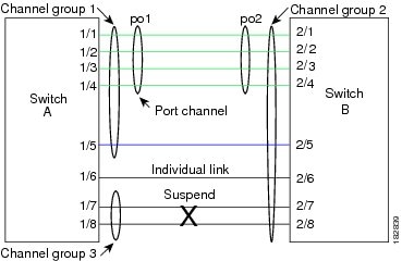
The Link Aggregation Control Protocol (LACP) allows you to configure up to 16 interfaces into a port channel. A maximum of eight interfaces can be active, and a maximum of eight interfaces can be placed in a standby state. The following figure shows how individual links can be combined into LACP port channels and channel groups as well as function as individual links.
- VEM Management of LACP
- Port Channel Modes
- LACP ID Parameters
- LACP Marker Responders
- LACP-Enabled and Static Port Channels Differences
VEM Management of LACP
You can offload operation of the LACP from the Virtual Supervisor Module (VSM) to the Virtual Ethernet Ports (VEMs) to prevent a situation where the VSM cannot negotiate LACP with the upstream switch when the VEM is disconnected from the VSM (referred to as headless mode). VEM management of LACP allows it to reestablish port channels after the reboot of a headless VEM.
Port Channel Modes
Individual interfaces in port channels are configured with channel modes. When you run static port channels with no aggregation protocol, the channel mode is always set to on.
You enable LACP for each channel by setting the channel mode for each interface to active or passive. You can configure either channel mode for individual links in the LACP channel group when you are adding the links to the channel group.
The following table describes the channel modes.
| Channel Mode | Description |
|---|---|
passive |
LACP mode that places a port into a passive negotiating state in which the port responds to LACP packets that it receives but does not initiate LACP negotiation. |
active |
LACP mode that places a port into an active negotiating state in which the port initiates negotiations with other ports by sending LACP packets. |
on |
All static port channels (that are not running LACP) remain in this mode. If you attempt to change the channel mode to active or passive before enabling LACP, the device displays an error message. You enable LACP on each channel by configuring the interface in that channel for the channel mode as either active or passive. When an LACP attempts to negotiate with an interface in the on state, it does not receive any LACP packets and becomes an individual link with that interface; it does not join the LACP channel group. The default port channel mode is on. |
Both the passive and active modes allow LACP to negotiate between ports to determine if they can form a port channel based on criteria such as the port speed and the trunking state. The passive mode is useful when you do not know whether the remote system, or partner, supports LACP.
Ports can form an LACP port channel when they are in different LACP modes if the modes are compatible as in these examples:
A port in active mode can form a port channel successfully with another port that is in active mode.
A port in active mode can form a port channel with another port in passive mode.
A port in passive mode cannot form a port channel with another port that is also in passive mode, because neither port will initiate negotiation.
A port in on mode is not running LACP and cannot form a port channel with another port that is in active or passive mode.
LACP ID Parameters
This section describes the LACP parameters.
LACP System Priority
Each system that runs LACP has an LACP system priority value. It has a default value of 32768 and is not configurable. LACP uses the system priority with the MAC address to form the system ID and also uses the system priority during negotiation with other devices. A higher system priority value means a lower priority.
Note | The LACP system ID is the combination of the LACP system priority value and the MAC address. |
LACP Port Priority
Each port that is configured to use LACP has an LACP port priority. It has a default value of 32768 and is not configurable. LACP uses the port priority with the port number to form the port identifier.
LACP uses the port priority to decide which ports should be put in standby mode when there is a limitation that prevents all compatible ports from aggregating and which ports should be put into active mode. A higher port priority value means a lower priority for LACP. You can configure the port priority so that specified ports have a lower priority for LACP and are most likely to be chosen as active links, rather than as hot-standby links.
LACP Administrative Key
LACP automatically configures an administrative key value that isequal to the channel entry index (1 through 8) for each port on the VEM configured to use LACP. The administrative key defines the ability of a port to aggregate with other ports. A port’s ability to aggregate with other ports is determined by these factors:
LACP Marker Responders
You can dynamically redistribute the data traffic by using port channels. This redistribution may result from a removed or added link or a change in the load-balancing scheme. Traffic redistribution that occurs in the middle of a traffic flow can cause misordered frames.
LACP uses the Marker Protocol to ensure that frames are not duplicated or reordered due to this redistribution. The Marker Protocol detects when all the frames of a given traffic flow are successfully received at the remote end. LACP sends Marker PDUs on each of the port-channel links. The remote system responds to the Marker PDU once it receives all the frames received on this link prior to the Marker PDU. The remote system then sends a Marker Responder. Once the Marker Responders are received by the local system on all member links of the port channel, the local system can redistribute the frames in the traffic flow with no chance of misordering. The software supports only Marker Responders.
LACP-Enabled and Static Port Channels Differences
The following table summarizes the major differences between port channels with LACP enabled and static port channels.
| Configurations | Port Channels with LACP Enabled | Static Port Channels |
|---|---|---|
Protocol applied |
Enable globally |
Not applicable |
Channel mode of links |
Can be either: |
Can only be On |
Maximum number of links in channel |
16 |
8 |
vPC Host Mode
You use vPC-HM mode to create a port channel when the switch is connected to multiple upstream switches that are not clustered. In the Cisco Nexus 1000V, the port channel is divided into subgroups or logical smaller port channels, each representing one or more uplinks to one upstream physical switch.
Links that connect to the same physical switch are bundled in the same subgroup automatically by using information gathered from the Cisco Discovery Protocol (CDP) packets from the upstream switch. Interfaces can also be manually assigned a specific subgroup.
When you use vPC-HM, each vEthernet interface on the VEM is mapped to one of two subgroups in a round-robin method. All traffic from the vEthernet interface uses the assigned subgroup unless it is unavailable, in which case the vEthernet interface fails over to the remaining subgroup. When the original subgroup becomes available again, traffic shifts back to it. Traffic from each vEthernet interface is then balanced based on the configured hashing algorithm.
When multiple uplinks are attached to the same subgroup, you must configure the upstream switch in a port channel with the links bundled together. The port channel must also be configured with the channel-group auto mode on (active and passive modes use LACP).
If the upstream switches do not support port channels, you can use MAC pinning to assign each Ethernet port member to a particular port channel subgroup.
Note | Do not configure vPC-HM on the Cisco Nexus 1000V when the upstream switch ports that connect to the VEMs have vPC configured. If vPC is configured, the connection can be interrupted or disabled. |
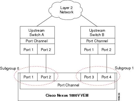
The following figure shows how to use vPC-HM to assign member ports 1 and 2 to subgroup ID 0 and member ports 3 and 4 to subgroup ID 1.
Subgroup Creation
If Cisco Discovery Protocol (CDP) is enabled on the upstream switches, subgroups are automatically created using information gathered from the CDP packets. If not, you must manually create subgroups.
Static Pinning
Static pinning allows you to pin the virtual ports behind a VEM to a particular subgroup within the channel. Instead of allowing round robin dynamic assignment between the subgroups, you can assign (or pin) a static vEthernet interface, control VLAN, or packet VLAN to a specific port channel subgroup. With static pinning, traffic is forwarded only through the member ports in the specified subgroup.
You can also pin vEthernet interfaces to subgroups in interface configuration mode.
MAC Pinning
If you are connecting to multiple upstream switches that do not support port channels, MAC pinning is the preferred configuration. MAC pinning divides the uplinks from your server into standalone links and pins the MAC addresses to those links in a round-robin method to ensure that the MAC address of a virtual machine is never seen on multiple upstream switch interfaces. Therefore, no upstream configuration is required to connect the VEM to upstream switches.
MAC pinning does not rely on any protocol to distinguish upstream switches so the configuration is independent of upstream hardware or design.
In the case of a failure, the Cisco Nexus 1000V first sends a gratuitous ARP packet to the upstream switch indicating that the VEM MAC address will now be learned on a different link. It also allows for subsecond failover time.
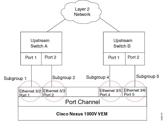
The following figure shows each member port that is assigned to a specific port channel subgroup using MAC pinning.
MAC Pinning Relative
This feature modifies the existing algorithm for MAC pinning where the port channel uses the port number (vmnic number) as the subgroup ID for an Ethernet member port.
The new algorithm assigns zero-based logical subgroup IDs to Ethernet member ports. The member port that has the lowest port number (vmnic number) is assigned subgroup ID 0.
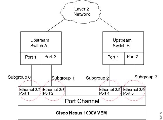
The following figure shows each member port that is assigned to a specific port channel subgroup using MAC pinning relative.
Network State Tracking for vPC-HM
Network state tracking for vPC-HM identifies link failures where other detection methods fail, and verifies Layer 2 connectivity between vPC-HM channel subgroups. It is not intended to detect network configuration problems.
Network state tracking selects one uplink interface in each sub group for broadcasting packets to a tracking VLAN. The tracking VLAN is usually the lowest forwarding VLAN for trunk ports and the primary VLAN for promiscuous access ports. The packets that are received back from the network on each subgroup are tracked as are the number of consecutively missed broadcasts. If the missed broadcasts for a subgroup exceed the threshold, the port channel is considered to be in split mode. In split mode, the interfaces are marked as inactive, and traffic is pinned to active interfaces.
System messages indicate when a port channel enters or recovers from split mode; and interfaces are marked active or inactive.
High Availability
Port channels provide high availability by load balancing traffic across multiple ports. If a physical port fails, the port channel is still operational if there is an active member in the port channel.
Port channels support stateful and stateless restarts. A stateful restart occurs on a supervisor switchover. After the switchover, the Cisco Nexus 1000V applies the runtime configuration after the switchover.
Prerequisites for Port Channels
Port channeling has the following prerequisites:
You are logged into the Cisco Nexus 1000V in EXEC mode.
All ports for a single port channel must meet the compatibility requirements. See Compatibility Checks for more information about the compatibility requirements.
You can use virtual vPC-HM to configure a port channel even when the physical ports are connected to two different switches.
Guidelines and Limitations
Port channeling has the following guidelines and restrictions:
-
All ports in the port channel must be in the same Cisco Nexus 1000V module; you cannot configure port channels across Cisco Nexus 1000V modules.
-
Port channels can be formed with multiple upstream links only when they satisfy the compatibility requirements and under the following conditions:
-
You can configure multiple port channels on a device.
-
After you configure a port channel, the configuration that you apply to the port channel interface affects the port channel member ports. The configuration that you apply to the member ports affects only the member port where you apply the configuration.
-
You must remove the port security information from a port before you can add that port to a port channel. You cannot apply the port security configuration to a port that is a member of a channel group.
-
You can configure ports that belong to a port channel group as PVLAN ports.
-
Any configuration changes that you apply to the port channel is applied to every member interface of that port channel.
-
Channel member ports cannot be source or destination SPAN ports.
-
To support LACP when inband/AIPC are also carried over the link, you must configure the following commands on the ports connected to the ESX host:
Note
If you have a separate dedicated NIC for control traffic, these settings are not required.
-
There should be at least two links that connect two switches when inband/AIPC are also carried over the LACP channel.
-
If you configure LACP and your upstream switch uses the LACP suspend feature, make sure this feature is disabled. For more information, see the documentation for your upstream switch.
-
If you are connecting to an upstream switch or switches that do not support port channels, MAC pinning is the preferred configuration. MAC pinning divides the uplinks from your server into standalone links and pins the MAC addresses to those links in a round-robin method. The drawback is that you cannot leverage the load sharing performance that LACP provides.
-
Once a port profile is created, you cannot change its type (Ethernet or vEthernet).
-
The server administrator should not assign more than one uplink on the same VLAN without port channels. The server administrator cannot assign more than one uplink on the same host to a profile without port channels or port profiles that share one or more VLANs.

Caution
Disruption of connectivity might result if you configure vPC-HM on the Cisco Nexus 1000V when vPC is also configured on the ports of upstream switches that connect to its VEMs.
-
You must have already configured the Cisco Nexus 1000Vsoftware using the setup routine. For information, see the Cisco Nexus 1000V Installation and Upgrade Guide.
-
The Cisco Nexus 1000V must be connected to the SCVMM.
-
You are logged in to the CLI in EXEC mode.
-
When you create a port channel, an associated channel group is automatically created.
-
If the Link Aggregation Control Protocol (LACP) support is required for the port channel, you must enable the LACP feature before you can configure it.
-
Network State Tracking is only supported with HP Virtual Connect where one physical link from the Flex-10 fabric appears as four Flex-10 NICs (physical NICs) to the VMkernel.
Default Settings
| Parameters | Default |
|---|---|
Port profile type |
vEthernet |
Port profile administrative state |
all ports disabled |
Port channel |
Admin up |
LACP |
Disabled |
Load balancing method for Layer 2 interfaces |
Source and destination MAC address |
Load balancing per module |
Disabled |
Channel mode |
on |
LACP offload (Offloading LACP management to VEMs) |
Enabled |
Network State Tracking: Broadcast interval |
5 seconds |
Network State Tracking: Split-network mode action |
repin |
Network State Tracking: Maximum threshold miss count |
5 seconds |
Network State Tracking: State |
Disabled |
Configuring Port Channels
Creating a Port Profile for a Port Channel
See the Cisco Nexus 1000V for Microsoft Hyper-V Network Segmentation Manager Configuration Guide for information about defining a port channel in a port profile, connecting to upstream networks, and pinning a vEthernet interface to a subgroup.
Migrating a Channel Group to a Port Profile
You can migrate a channel group to a port profile.
You are logged in to the CLI in EXEC mode.
| Step 1 | Place the host in maintenance mode. | ||
| Step 2 | Do one of the following: | ||
| Step 3 | When all the virtual machines are successfully migrated, from the Cisco Nexus 1000V CLI, create a new Ethernet type port profile for the uplink ports on this host with the needed parameters including the following. | ||
| Step 4 | Remove the port channel configuration from the uplink switches.
| ||
| Step 5 | When all the port(s) are moved from the old port profile, use the following command from the Cisco Nexus 1000V CLI to delete the port channels with zero members:no interface port-channel id | ||
| Step 6 | Bring the host out of maintenance mode. | ||
| Step 7 | Use the following command from the Cisco Nexus 1000V to save the running configuration persistently through reboots and restarts by copying it to the startup configuration. copy running-config startup-config | ||
| Step 8 | Create the port channel type in the upstream switch. See Creating a Port Profile for a Port Channel. |
Migrating Port Profile Types in a Port Profile
To move port profile types in a port profile, you tear down the existing port channel then recreate the port channel. These steps use procedures documented in other sections of this chapter.
You are logged in to the CLI in EXEC mode.
| Step 1 | Place the host in maintenance mode. | ||
| Step 2 | Do one of the following: | ||
| Step 3 | When all the virtual machines are successfully migrated, from the Cisco Nexus 1000V CLI, create a new Ethernet type port profile for the uplink ports on this host with the needed parameters including the following. | ||
| Step 4 | Remove the port channel you want to migrate in the upstream switch. See Removing a Port Channel Group from a Port Profile. | ||
| Step 5 | Remove the port channel in the upstream switch. | ||
| Step 6 | Manually configure subgroup IDs in the Cisco Nexus 1000V Ethernet interface. See Manually Configuring Interface Subgroups
| ||
| Step 7 | Change the port channel type in the Cisco Nexus 1000V port profile. See Migrating a Channel Group to a Port Profile | ||
| Step 8 | Change the port channel type in the Cisco Nexus 1000V port profile. See Connecting to a Single Upstream Switch | ||
| Step 9 | Bring the host out of maintenance mode. | ||
| Step 10 | Migrate the virtual machines back to this host. | ||
| Step 11 | Use the following command from the Cisco Nexus 1000V to save the running configuration persistently through reboots and restarts by copying it to the startup configuration. copy running-config startup-config | ||
| Step 12 | Create the port channel type you want in the upstream switch. See Creating a Port Profile for a Port Channel. |
Configuring Network State Tracking for vPC-HM
You can configure Network State Tracking to pinpoint link failures on port channels configured for vPC-HM.
You are logged in to the CLI in EXEC mode.
Once enabled, Network State Tracking is used on every VEM that is configured with a vPC-HM port profile.
If you specify repinning (the default) and a split network is detected, then Ethernet interfaces are inactivated, and the vEths are redistributed among all interfaces including the reactivated Ethernet interfaces. Restoration to the earlier pinned state is not guaranteed.
The following example shows how to configure Network State Tracking with an 8 second interval between each sent broadcast, repinning traffic to another uplink if a split network is detected, and a maximum of 7 missed broadcasts before declaring a split network:
switch# configure terminal
switch(config)# track network-state enable
switch(config)# track network-state interval 8
switch(config)# track network-state split action repin
switch(config)# track network-state threshold miss-count 7
switch(config)# show network-state tracking config
Tracking mode        : enabled
Tracking Interval    : 8 sec
Miss count threshold : 7 pkts
Split-network action : repin
switch(config)#
Configuring Static Pinning for an Interface
You can configure static pinning on a vEthernet interface.
Note | You can also pin a subgroup to a vEthernet interface in the port profile configuration. See Pinning a vEthernet Interface to a Subgroup. |
You are logged in to the CLI in EXEC mode.
The following example shows how to pin subgroup ID 0 to vEthernet interface 1:
switch# configure terminal
switch(config)# interface vethernet 1
switch(config-if)# pinning id 0
switch(config-if)# show running-config interface vethernet 1
version 4.0(4)SV1(2)

interface Vethernet3
  service-policy type qos input policy1
  pinning id 0

switch(config-if)# exit
switch(config)# exit
switch# module vem 3 execute vemcmd show pinning
  LTL    IfIndex  PC_LTL  VSM_SGID  VEM_SGID  Eff_SGID
   48   1b040000     304         0         0         0
switch#
The following example shows the output after configuring backup subgroups for pinning:
switch(config-if)# module vem 4 execute vemcmd show static pinning config
  LTL    IfIndex   VSM_SGID  Backup_SGID
   48   1c0000a0      0,          1,2
   50   1c000100      0,          1

switch(config-if)# copy running-config startup-config
Removing a Port Channel Group from a Port Profile
You can remove a port channel group from a port profile.
You are logged in to the CLI in EXEC mode.
This example shows how to remove a port channel group from a port profile:
switch# configure terminal
switch(config)# uplink-network up-pc
switch(config-uplink-net)#  no import port-profile pc
switch(config-uplink-net)#  show uplink-network name up-pcuplink-network: up-pc
Publish-name: up-pc
import port-profile: uplink_network_default_policy <<<<<<<<<<<<<<<<<<<<
network-definition:
ndef1
ndef2
port-profile config:
switchport mode trunk
switchport trunk allowed vlan 400,500
switch(config-uplink-net)#
Shutting Down and Restarting a Port Channel Interface
You can shut down and restart a port channel interface.
The following example shows how to bring up the interface for port channel 2:
switch# configure terminal
switch(config)# interface port-channel 2
switch(config-if)# no shutdown
Adding a Description to a Port Channel Interface
You can add a description to a port channel interface.
You are logged in to the CLI in EXEC mode.
The following example shows how to add a description to port channel 2:
switch# configure terminal
switch(config)# interface port-channel 2
switch(config-if)# description engineering
Configuring Port Channel Load Balancing
You can configure port channel load balancing.
| Command or Action | Purpose | |
|---|---|---|
| Step 1 | switch# configure terminal |
Enters global configuration mode. |
| Step 2 | switch(config)# port-channel load-balance ethernet { dest-ip-port | dest-ip-port-vlan | destination-ip-vlan | destination-mac | destination-port | source-dest-ip-port | source-dest-ip-port-vlan | source-dest-ip-vlan | source-dest-mac | source-dest-port | source-ip-port | source-ip-port-vlan | source-ip-vlan | source-mac | source-port | source-virtual-port-id | vlan-only } | Configures the load balance method for the device or module. The range depends on the device. The default load balancing method uses the source MAC address. |
| Step 3 | switch(config)# show interface port-channel load balance | (Optional) Displays the port channel load-balancing method. |
| Step 4 | switch(config)# copy running-config startup-config | (Optional)
Saves the change persistently through reboots and restarts by copying the running configuration to the startup configuration. |
The following example shows how to configure the source IP load-balancing method for port channels on module 5:
switch# configure terminal
switch# interface port channel 2
switch# port-channel load-balance ethernet source-ip module 5
Configuring the Speed and Duplex Settings for a Port Channel Interface
You can configure the speed and duplex settings for a port channel interface.
| Command or Action | Purpose | |
|---|---|---|
| Step 1 | switch# configure terminal |
Enters global configuration mode. |
| Step 2 | switch(config)# interface port-channel channel-number | Specifies the port channel interface that you want to configure and enters the interface mode. Allowable channel numbers are from 1 to 4096. |
| Step 3 | switch(config-if)# speed { 10 | 100 | 1000 | auto } | Sets the speed for the port channel interface. The default is auto for autonegotiation. |
| Step 4 | switch(config-if)# duplex { auto | full | half } | Sets the duplex mode for the port channel interface. The default is auto for autonegotiation. |
| Step 5 | switch(config-if)# show interface port-channel channel-number | (Optional) Displays interface information for the specified port channel. |
| Step 6 | switch(config-if)# copy running-config startup-config | (Optional)
Saves the change persistently through reboots and restarts by copying the running configuration to the startup configuration. |
The following example shows how to set port channel 2 to 100 Mbps:
switch# configure terminal
switch(config)# interface port channel 2
switch(config-if)# speed 100
Restoring the Default Load-Balancing Method
You can restore the default load-balancing method.
You are logged in to the CLI in EXEC mode.
| Command or Action | Purpose | |
|---|---|---|
| Step 1 | switch# configure terminal |
Enters global configuration mode. |
| Step 2 | switch(config)# no port-channel load-balance ethernet | Restores the default load-balancing method, which is the source MAC address. |
| Step 3 | switch(config)# show interface port-channel load balance | (Optional) Displays the port channel load-balancing method. |
| Step 4 | switch(config)# copy running-config startup-config | (Optional)
Saves the change persistently through reboots and restarts by copying the running configuration to the startup configuration. |
The following example shows how to restore the default load balancing method:
switch# configure terminal
switch(config)# no port-channel load-balance ethernet
switch(config)# show port-channel load-balance
Configuring an LACP Port Channel
You can configure the following requirements for LACP:
You are logged in to the CLI in EXEC mode.
The default port channel mode is on.
The LACP feature support must be enabled before you can configure LACP. This procedure has a step for enabling the LACP feature.
When you configure port channels with no associated aggregation protocol, all interfaces on both sides of the link remain in the on channel mode.
The LACP mode for individual links in an LACP port channel indicates that the link is allowed to operate with LACP.
You have defined a native VLAN for the trunk port. Although it may not be used for data, the native VLAN is used for LACP negotiation. If you want traffic forwarded on the native VLAN of the trunk port, the native VLAN must be in the allowed VLAN list and system VLAN list.
This procedure includes steps to add VLANs to the allowed VLAN list and system VLAN list for the port channel.
| Command or Action | Purpose | |||
|---|---|---|---|---|
| Step 1 | switch# configure terminal |
Enters global configuration mode. | ||
| Step 2 | switch(config)# feature lacp | Enables LACP support for port channels. | ||
| Step 3 | switch(config-if)# port-profile [ type { ethernet | vethernet }] name | Enters port profile configuration mode for the named port profile.
For configuring port channels, specify the port profile as an Ethernet type. Defining a port profile as an Ethernet type allows the port profile to be used for physical (Ethernet) ports. In the SCVMM, the corresponding port group can be selected and assigned to physical ports (PNICs).
| ||
| Step 4 | switch(config-port-prof)# switchport mode { access | private-vlan { host | promiscuous } | trunk } | Designates how the interfaces are to be used. Allowable port modes: A trunk port transmits untagged packets for the native VLAN and transmits encapsulated, tagged packets for all other VLANs. | ||
| Step 5 | switch(config-port-prof)# switchport trunk allowed vlan vlan-id-list | Designates the port profile as trunking and defines VLAN access to it as follows:
If you do not configure allowed VLANs, then the default VLAN 1 is used as the allowed VLAN. If you want traffic forwarded on the native VLAN of the trunk port, the native VLAN must be in the allowed VLAN list. | ||
| Step 6 | switch(config-port-prof)# show port-profile name | (Optional)
Displays the configuration for verification. | ||
| Step 7 | switch(config-port-prof)# copy running-config startup-config | (Optional)
Saves the change persistently through reboots and restarts by copying the running configuration to the startup configuration. |
This example shows how to remove a port channel group from a port profile:
switch# configure terminal
switch(config)# port-profile testProf
switch(config-port-prof)# no channel-group auto
switch(config-port-prof)# show port-profile testProf
switch(config-port-prof)#
Verifying Port Channel Configuration
Use the following commands to verify the port channel configuration:
| Command | Purpose |
|---|---|
show feature |
Displays the features available, such as LACP, and whether they are enabled. |
show interface port-channel channel-number |
Displays the status of a port channel interface. |
show lacp port-channel [ interface port-channel channel-number ] |
Displays information about LACP port channels. |
show lacp interface ethernet slot/port |
Displays information about specific LACP interfaces. |
show lacp offload status |
Displays whether LACP management is offloaded to the VEMs. |
show network-state tracking config |
Displays the Network State Tracking configuration for verification. |
show network-state tracking { module modID | interface channelID} |
Displays the Network State Tracking status for a module or interface. |
show port-channel compatibility-parameters |
Displays the parameters that must be the same among the member ports in order to join a port channel. |
show port-channel database [ interface port-channel channel-number ] |
Displays the aggregation state for one or more port channel interfaces. |
show port-channel load-balance |
Displays the type of load balancing in use for port channels. |
show port-channel summary |
Displays a summary for the port channel interfaces. |
show port-channel traffic |
Displays the traffic statistics for port channels. |
show port-channel usage |
Displays the range of used and unused channel numbers. |
show running-config interface ethernet port/slot |
Displays information about the running configuration of the specified Ethernet interface. |
show running-config interface port-channel channel-number |
Displays information on the running configuration of the port channel. |
show running-config interface vethernet interface-number |
Displays information about the running configuration of the specified vEthernet interface. |
Monitoring Port Channels
Use the following commands to monitor the port channel interface configuration:
| Command | Purpose |
|---|---|
clear counters interface port-channel channel-number |
Clears the counters. |
show interface counters [ module module ] |
Displays input and output octets unicast packets, multicast packets, and broadcast packets. |
show interface counters detailed [ all ] |
Displays input packets, bytes, and multicast and output packets and bytes. |
show interface counters errors [ module module ] |
Displays information on the number of error packets. |
show lacp counters [ interface port-channel channel-number ] |
Displays information about LACP statistics. |
Configuration Examples for Port Channels
Configuration Example: Create a Port Channel and Add Interfaces
The following example shows how to create a port channel and add two Layer 2 interfaces to that port channel:
switch# configure terminal
switch(config)# interface port-channel 5
switch(config-if)# interface ethernet 1/4
switch(config-if)# switchport
switch(config-if)# channel-group 5 mode active
switch(config-if)# interface ethernet 1/7
switch(config-if)# switchport
switch(config-if)# channel-group 5 mode
switch(config-if)#
Configuration Example: Create an LACP Port Channel
The following example shows how to set the LACP-enabled interface to the active port channel mode for Ethernet interface 1/4 in channel group 5; and then configure an LACP port profile for the port channel:
switch# configure terminal
switch(config)# feature lacp
switch(config)# interface ethernet 1/4
switch(config-if)# channel-group 5 mode active
switch(config-if)# port-profile type ethernet system-uplink
switch(config-port-prof)# switchport mode trunk
switch(config-port-prof)# switchport trunk allowed vlan 1-100
switch(config-port-prof)# channel-group auto mode active
switch(config-port-prof)# system vlan 1,10,20
switch(config-port-prof)# state enabled
switch(config-port-prof)# show port-channel summary
switch(config-port-prof)# copy running-config startup-config
Configuration Example: Configuring Network State Tracking for vPC-HM
The following example shows how to configure Network State Tracking with an 8 second interval between sent broadcasts, a maximum of 7 missed broadcasts before declaring a split network, and repin traffic to another uplink if a split network is detected:
switch# configure terminal
switch(config)# track network-state enable
switch(config)# track network-state interval 8
switch(config)# track network-state split action repin
switch(config)# track network-state threshold miss-count 7
switch(config)# show network-state tracking config
Tracking mode        : enabled
Tracking Interval    : 8 sec
Miss count threshold : 7 pkts
Split-network action : repin
switch(config)#
Feature History for Port Channels
Feature Name |
Releases |
Feature Information |
|---|---|---|
Port Channels |
5.2(1)SM1(5.1) |
This feature was introduced. |
 Feedback