IP Services Configuration Guide, Cisco DCNM for SAN, Release 7.0.x
Bias-Free Language
The documentation set for this product strives to use bias-free language. For the purposes of this documentation set, bias-free is defined as language that does not imply discrimination based on age, disability, gender, racial identity, ethnic identity, sexual orientation, socioeconomic status, and intersectionality. Exceptions may be present in the documentation due to language that is hardcoded in the user interfaces of the product software, language used based on RFP documentation, or language that is used by a referenced third-party product. Learn more about how Cisco is using Inclusive Language.
- Updated:
- April 20, 2015
Chapter: Configuring IPv4 for Gigabit Ethernet Interfaces
Configuring IPv4 for Gigabit Ethernet Interfaces
Cisco MDS 9000 Family switches support IP version 4 (IPv4) on Gigabit Ethernet interfaces. This chapter describes how to configure IPv4 addresses and other IPv4 features.
Information About IPv4
Cisco MDS 9000 Family supports IP version 4 (IPv4) on Gigabit Ethernet interfaces. Both FCIP and iSCSI rely on TCP/IP for network connectivity. On each IPS module or MPS-14/2 module, connectivity is provided in the form of Gigabit Ethernet interfaces that are appropriately configured.
A new port mode, called IPS, is defined for Gigabit Ethernet ports on each IPS module or MPS-14/2 module. IP storage ports are implicitly set to IPS mode, so it can only be used to perform iSCSI and FCIP storage functions. IP storage ports do not bridge Ethernet frames or route other IP packets.
Each IPS port represents a single virtual Fibre Channel host in the Fibre Channel SAN. All the iSCSI hosts connected to this IPS port are merged and multiplexed through the single Fibre Channel host.

Note![]() The Gigabit Ethernet interfaces on the MPS-14/2 module do not support EtherChannel.
The Gigabit Ethernet interfaces on the MPS-14/2 module do not support EtherChannel.
Both FCIP and iSCSI rely on TCP/IP for network connectivity. On each IPS module or MPS-14/2 module, connectivity is provided in the form of Gigabit Ethernet interfaces that are appropriately configured. This section covers the steps required to configure IP for subsequent use by FCIP and iSCSI.
Note![]() For information about configuring FCIP, see Chapter2, “Configuring FCIP” For information about configuring iSCSI, see Chapter4, “Configuring iSCSI”
For information about configuring FCIP, see Chapter2, “Configuring FCIP” For information about configuring iSCSI, see Chapter4, “Configuring iSCSI”
A new port mode, called IPS, is defined for Gigabit Ethernet ports on each IPS module or MPS-14/2 module. IP storage ports are implicitly set to IPS mode, so it can only be used to perform iSCSI and FCIP storage functions. IP storage ports do not bridge Ethernet frames or route other IP packets.
Each IPS port represents a single virtual Fibre Channel host in the Fibre Channel SAN. All the iSCSI hosts connected to this IPS port are merged and multiplexed through the single Fibre Channel host.
In large scale iSCSI deployments where the Fibre Channel storage subsystems do not require explicit LUN access control for every host device, use of proxy-initiator mode simplifies the configuration.
Note![]() The Gigabit Ethernet interfaces on the MPS-14/2 module do not support EtherChannel.
The Gigabit Ethernet interfaces on the MPS-14/2 module do not support EtherChannel.
Note![]() To configure IPv6 on a Gigabit Ethernet interface, see the “Configuring IPv6 Addressing and Enabling IPv6 Routing” section.
To configure IPv6 on a Gigabit Ethernet interface, see the “Configuring IPv6 Addressing and Enabling IPv6 Routing” section.

Tip![]() Gigabit Ethernet ports on any IPS module or MPS-14/2 module should not be configured in the same Ethernet broadcast domain as the management Ethernet port. They should be configured in a different broadcast domain, either by using separate standalone hubs or switches or by using separate VLANs.
Gigabit Ethernet ports on any IPS module or MPS-14/2 module should not be configured in the same Ethernet broadcast domain as the management Ethernet port. They should be configured in a different broadcast domain, either by using separate standalone hubs or switches or by using separate VLANs.
This section includes the following topics:
Interface Descriptions
See the Inferfaces Configuration Guide, Cisco DCNM for SANCisco MDS 9000 Family NX-OS Interfaces Configuration Guide for details on configuring the switch port description for any interface.
Beacon Mode
See the Inferfaces Configuration Guide, Cisco DCNM for SANCisco MDS 9000 Family NX-OS Interfaces Configuration Guide for details on configuring the beacon mode for any interface.
About VLANs for Gigabit Ethernet
Virtual LANs (VLANs) create multiple virtual Layer 2 networks over a physical LAN network. VLANs provide traffic isolation, security, and broadcast control.
Gigabit Ethernet ports automatically recognize Ethernet frames with IEEE 802.1Q VLAN encapsulation. If you need to have traffic from multiple VLANs terminated on one Gigabit Ethernet port, configure subinterfaces—one for each VLAN.
Note If the IPS module or MPS-14/2 module is connected to a Cisco Ethernet switch, and you need to have traffic from multiple VLANs coming to one IPS port, verify the following requirements on the Ethernet switch:
- The Ethernet switch port connected to the IPS module or MPS-14/2 module is configured as a trunking port.
- The encapsulation is set to 802.1Q and not ISL, which is the default.
Use the VLAN ID as a subscription to the Gigabit Ethernet interface name to create the subinterface name:
Interface Subnet Requirements
Gigabit Ethernet interfaces (major), subinterfaces (VLAN ID), and management interfaces (mgmt 0) can be configured in the same or different subnet depending on the configuration (see Table 7-1 ).
Note![]() The configuration requirements in Table 7-1 also apply to Ethernet PortChannels.
The configuration requirements in Table 7-1 also apply to Ethernet PortChannels.
Licensing Requirements for IPv4 for Gigabit Ethernet Interfaces
The following table shows the licensing requirements for this feature:
|
|
|
|---|---|
Guidelines and Limitations
Follow these guidelines when configuring IPv4-ACLs for Gigabit Ethernet interfaces:
Note![]() Other protocols such as User Datagram Protocol (UDP) and HTTP are not supported in Gigabit Ethernet interfaces. Applying an ACL that contains rules for these protocols to a Gigabit Ethernet interface is allowed but those rules have no effect.
Other protocols such as User Datagram Protocol (UDP) and HTTP are not supported in Gigabit Ethernet interfaces. Applying an ACL that contains rules for these protocols to a Gigabit Ethernet interface is allowed but those rules have no effect.
- Apply IPv4-ACLs to the interface before you enable an interface. This ensures that the filters are in place before traffic starts flowing.
- Be aware of the following conditions:
–![]() If you use the log-deny option, a maximum of 50 messages are logged per second.
If you use the log-deny option, a maximum of 50 messages are logged per second.
–![]() The established option is ignored when you apply IPv4-ACLs containing this option to Gigabit Ethernet interfaces.
The established option is ignored when you apply IPv4-ACLs containing this option to Gigabit Ethernet interfaces.
–![]() If an IPv4-ACL rule applies to a pre-existing TCP connection, that rule is ignored. For example if there is an existing TCP connection between A and B and an IPv4-ACL which specifies dropping all packets whose source is A and destination is B is subsequently applied, it will have no effect.
If an IPv4-ACL rule applies to a pre-existing TCP connection, that rule is ignored. For example if there is an existing TCP connection between A and B and an IPv4-ACL which specifies dropping all packets whose source is A and destination is B is subsequently applied, it will have no effect.
Tip![]() If IPv4-ACLs are already configured in a Gigabit Ethernet interface, you cannot add this interface to an Ethernet PortChannel group.
If IPv4-ACLs are already configured in a Gigabit Ethernet interface, you cannot add this interface to an Ethernet PortChannel group.
Default Settings
Table 7-2 lists the default settings for IPv4 parameters.
|
|
|
|---|---|
Configuring IPv4
This section includes the following topics:
- Configuring Gigabit Ethernet Interface
- Configuring Autonegotiation
- Configuring the MTU Frame Size
- Configuring Promiscuous Mode
- Configuring the VLAN Subinterface
- Configuring Static IPv4 Routing
- Applying IPv4-ACLs on Gigabit Ethernet Interfaces
- Clearing ARP Cache
Configuring Gigabit Ethernet Interface
Detailed Steps
To configure the Gigabit Ethernet interface, follow these steps:
Step 1![]() Expand Switches > Interfaces > Ethernet > IPS.
Expand Switches > Interfaces > Ethernet > IPS.
You see the Gigabit Ethernet Configuration in the Information pane.
Step 2![]() Click the IP Addresses tab.
Click the IP Addresses tab.
You see the Create Gigabit Ethernet Interface dialog box.
Step 4![]() Select the switch on which you want to create the Gigabit Ethernet interface.
Select the switch on which you want to create the Gigabit Ethernet interface.
Step 5![]() Enter the interface. For example, 2/2 for slot 2, port 2.
Enter the interface. For example, 2/2 for slot 2, port 2.
Step 6![]() Enter the IPv4 address (10.1.1.100) and subnet mask (255.255.255.0).
Enter the IPv4 address (10.1.1.100) and subnet mask (255.255.255.0).
Step 7![]() Click Create to save these changes or click Close to discard any unsaved changes.
Click Create to save these changes or click Close to discard any unsaved changes.
Configuring Autonegotiation
By default, autonegotiation is enabled all Gigabit Ethernet interface. You can enable or disable autonegotiation for a specified Gigabit Ethernet interface. When autonegotiation is enabled, the port automatically detects the speed or pause method, and duplex of incoming signals based on the link partner. You can also detect link up conditions using the autonegotiation feature.
Detailed Steps
To configure autonegotiation, follow these steps:
To configure autonegotiation, follow these steps:
Step 1![]() Expand Switches > Interfaces > Ethernet > IPS.
Expand Switches > Interfaces > Ethernet > IPS.
You see the Gigabit Ethernet Configuration in the Information pane.
Step 2![]() In the General tab, you can enable or disable the Auto Negotiate option for a specific switch.
In the General tab, you can enable or disable the Auto Negotiate option for a specific switch.
Configuring the MTU Frame Size
You can configure the interfaces on a switch to transfer large (or jumbo) frames on a port. The default IP maximum transmission unit (MTU) frame size is 1500 bytes for all Ethernet ports. By configuring jumbo frames on a port, the MTU size can be increased up to 9000 bytes.
Note![]() The minimum MTU size is 576 bytes.
The minimum MTU size is 576 bytes.
Tip![]() MTU changes are disruptive, all FCIP links and iSCSI sessions flap when the software detects a change in the MTU size.
MTU changes are disruptive, all FCIP links and iSCSI sessions flap when the software detects a change in the MTU size.
You do not need to explicitly issue the shutdown and no shutdown commands.
Detailed Steps
To configure the MTU frame size, follow these steps:
|
|
|
|
|---|---|---|
Enters the interface configuration mode on the Gigabit Ethernet interface (slot 2, port 2). |
||
Changes the MTU size to 3000 bytes. The default is 1500 bytes. |
To configure the MTU frame size, follow these steps:
Step 1![]() Expand Switches > Interfaces > Ethernet > IPS.
Expand Switches > Interfaces > Ethernet > IPS.
You see the Gigabit Ethernet Configuration in the Information pane.
Step 2![]() In the General tab, in the Mtu column, you can enter a new value to configure the MTU Frame Size for a specific switch. For example 3000 bytes. The default is 1500 bytes.
In the General tab, in the Mtu column, you can enter a new value to configure the MTU Frame Size for a specific switch. For example 3000 bytes. The default is 1500 bytes.
Configuring Promiscuous Mode
You can enable or disable promiscuous mode on a specific Gigabit Ethernet interface. By enabling the promiscuous mode, the Gigabit Ethernet interface receives all the packets and the software then filters and discards the packets that are not destined for that Gigabit Ethernet interface.
Detailed Steps
To configure the promiscuous mode, follow these steps:
To configure the promiscuous mode, follow these steps:
Step 1![]() Expand Switches > Interfaces > Ethernet > IPS.
Expand Switches > Interfaces > Ethernet > IPS.
You see the Gigabit Ethernet Configuration in the Information pane.
Step 2![]() In the General tab, you can enable or disable the Promiscuous Mode option for a specific switch.
In the General tab, you can enable or disable the Promiscuous Mode option for a specific switch.
Configuring the VLAN Subinterface
Detailed Steps
To configure a VLAN subinterface (VLAN ID), follow these steps:
To configure a VLAN subinterface (VLAN ID) using Device Manager, follow these steps:
Step 1![]() Select Interface > Ethernet and iSCSI.
Select Interface > Ethernet and iSCSI.
Step 2![]() Click the Sub Interfaces tab.
Click the Sub Interfaces tab.
Step 3![]() Select the Gigabit Ethernet subinterface on which 802.1Q should be used.
Select the Gigabit Ethernet subinterface on which 802.1Q should be used.
Step 4![]() Click the Edit IP Address button.
Click the Edit IP Address button.
Step 5![]() Enter the IPv4 address and subnet mask for the Gigabit Ethernet interface.
Enter the IPv4 address and subnet mask for the Gigabit Ethernet interface.
Step 6![]() Click Create to save the changes or you may click Close.
Click Create to save the changes or you may click Close.
Configuring Static IPv4 Routing
Detailed Steps
To configure static IPv4 routing (see Figure 7-1) through the Gigabit Ethernet interface, follow these steps:
Applying IPv4-ACLs on Gigabit Ethernet Interfaces
Detailed Steps
To apply an IPv4-ACL on a Gigabit Ethernet interface, follow these steps:
Clearing ARP Cache
Detailed Steps
The ARP cache can be cleared in two ways: clearing just one entry or clearing all entries in the ARP cache.
Use the clear ips arp command to clear the ARP cache. See Example 7-1 and Example 7-2.
Examples
Example 7-1 Clearing One ARP Cache Entry
Example 7-2 Clearing All ARP Cache Entries
Verifying IPV4 Configuration
To display IPv4 configuration information, perform one of the following tasks:
|
|
|
|---|---|
clear ips arp address 10.2.2.2 interface gigabitethernet 8/7 |
|
This section includes the followin topics:
- Verifying Gigabit Ethernet Connectivity
- Displaying the IPv4 Route Table
- Displaying ARP Cache
- Displaying IPv4 Statistics
Verifying Gigabit Ethernet Connectivity
Once the Gigabit Ethernet interfaces are connected with valid IP addresses, verify the interface connectivity on each switch. Ping the IP host using the IP address of the host to verify that the static IP route is configured correctly.
Note![]() If the connection fails, verify the following, and ping the IP host again:
If the connection fails, verify the following, and ping the IP host again:
- The IP address for the destination (IP host) is correctly configured.
- The host is active (powered on).
- The IP route is configured correctly.
- The IP host has a route to get to the Gigabit Ethernet interface subnet.
- The Gigabit Ethernet interface is in the up state.
Use the ping command to verify the Gigabit Ethernet connectivity (see Example 7-3). The ping command sends echo request packets out to a remote device at an IP address that you specify (see the “Using the ping and ping ipv6 Commands”).
Use the show interface gigabitethernet command to verify if the Gigabit Ethernet interface is up.
Example 7-3 Verifying Gigabit Ethernet Connectivity
Displaying the IPv4 Route Table
The ip route interface command takes the Gigabit Ethernet interface as a parameter and returns the route table for the interface. See Example 7-4.
Example 7-4 Displays the IP Route Table
Connected (C) identifies the subnet in which the interface is configured (directly connected to the interface). Static (S) identifies the static routes that go through the router.
Displaying ARP Cache
You can display the ARP cache on Gigabit Ethernet interfaces.
Note![]() Use the physical interface, not the subinterface, for all ARP cache commands.
Use the physical interface, not the subinterface, for all ARP cache commands.
Use the show ips arp interface gigabitethernet command to display the ARP cache on the Gigabit Ethernet interfaces. This command takes the Ethernet interface as a parameter and returns the ARP cache for that interface. See Example 7-5.
Example 7-5 Displays ARP Caches
Displaying IPv4 Statistics
Use the show ips stats ip interface gigabitethernet to display and verify IP v4 statistics. This command takes the main Ethernet interface as a parameter and returns the IPv4 statistics for that interface. See Example 7-6.
Note![]() Use the physical interface, not the subinterface, to displayIPv4 statistics.
Use the physical interface, not the subinterface, to displayIPv4 statistics.
Example 7-6 Displays IPv4 Statistics
Configuration Examples for IPV4
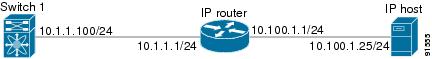
Figure 7-1 shows an example of a basic Gigabit Ethernet IP version 4 (IPv4) configuration.
Figure 7-1 Gigabit Ethernet IPv4 Configuration Example
Note![]() The port on the Ethernet switch to which the MDS Gigabit Ethernet interface is connected should be configured as a host port (also known as access port) instead of a switch port. Spanning tree configuration for that port (on the Ethernet switch) should be disabled. This helps avoid the delay in the management port coming up due to delay from Ethernet spanning tree processing that the Ethernet switch would run if enabled. For Cisco Ethernet switches, use either the switchport host command in Cisco IOS or the set port host command in the Catalyst OS.
The port on the Ethernet switch to which the MDS Gigabit Ethernet interface is connected should be configured as a host port (also known as access port) instead of a switch port. Spanning tree configuration for that port (on the Ethernet switch) should be disabled. This helps avoid the delay in the management port coming up due to delay from Ethernet spanning tree processing that the Ethernet switch would run if enabled. For Cisco Ethernet switches, use either the switchport host command in Cisco IOS or the set port host command in the Catalyst OS.
To configure the Gigabit Ethernet interface for the example in Figure 7-1, follow these steps:
Additional References
For additional information related to implementing FCIPs, see the following section:
Related Document
|
|
|
|---|---|
Standards
|
|
|
|---|---|
No new or modified standards are supported by this feature, and support for existing standards has not been modified by this feature. |
RFCs
|
|
|
|---|---|
No new or modified RFCs are supported by this feature, and support for existing RFCs has not been modified. |
MIBs
|
|
|
|---|---|
 Feedback