IP Services Configuration Guide, Cisco DCNM for SAN, Release 6.x
Bias-Free Language
The documentation set for this product strives to use bias-free language. For the purposes of this documentation set, bias-free is defined as language that does not imply discrimination based on age, disability, gender, racial identity, ethnic identity, sexual orientation, socioeconomic status, and intersectionality. Exceptions may be present in the documentation due to language that is hardcoded in the user interfaces of the product software, language used based on RFP documentation, or language that is used by a referenced third-party product. Learn more about how Cisco is using Inclusive Language.
- Updated:
- June 21, 2012
Chapter: Configuring the SAN Extension Tuner
Configuring the SAN Extension Tuner
The SAN Extension Tuner (SET) feature is unique to the Cisco MDS 9000 Family of switches. This feature helps you optimize FCIP performance by generating either direct access (magnetic disk) or sequential access (magnetic tape) SCSI I/O commands and directing such traffic to a specific virtual target. You can specify the size of the test I/O transfers and how many concurrent or serial I/Os to generate while testing. The SET reports the resulting I/Os per second (IOPS) and I/O latency, which helps you determine the number of concurrent I/Os needed to maximize FCIP throughput.
Information About the SAN Extension Tuner
The SAN extension tuner (SET) feature is unique to the Cisco MDS 9000 Family of switches. This feature helps you optimize FCIP performance by generating either direct access (magnetic disk) or sequential access (magnetic tape) SCSI I/O commands and directing such traffic to a specific virtual target. Applications such as remote copy and data backup use FCIP over an IP network to connect across geographically distributed SANs. SET is implemented in IPS ports. When enabled, this feature can be used to generate SCSI I/O commands (read and write) to the virtual target based on your configured options.

Note![]() SAN Extension Tuner is not supported on the Cisco Fabric Switch for HP c-Class BladeSystem, the Cisco Fabric Switch for IBM BladeCenter, and 16-Port Storage Services Node (SSN-16).
SAN Extension Tuner is not supported on the Cisco Fabric Switch for HP c-Class BladeSystem, the Cisco Fabric Switch for IBM BladeCenter, and 16-Port Storage Services Node (SSN-16).
Note![]() As of Cisco MDS SAN-OS Release 3.3(1a), SAN Extension Tuner is supported on the Multiservice Module (MSM) and the Multiservice Modular Switch.
As of Cisco MDS SAN-OS Release 3.3(1a), SAN Extension Tuner is supported on the Multiservice Module (MSM) and the Multiservice Modular Switch.
Applications such as remote copy and data backup use FCIP over an IP network to connect across geographically distributed SANs. To achieve maximum throughput performance across the fabric, you can tune the following configuration parameters:
- The TCP parameters for the FCIP profile.
- The number of concurrent SCSI I/Os generated by the application.
- The transfer size used by the application over an FCIP link.
SET is implemented in IPS ports. When enabled, this feature can be used to generate SCSI I/O commands (read and write) to the virtual target based on your configured options (see Figure 3-1).
Figure 3-1 SCSI Command Generation to the Virtual Target
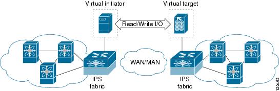
The SET feature assists with tuning by generating varying SCSI traffic workloads. It also measures throughput and response time per I/ O over an FCIP link.
Before tuning the SAN fabric, be aware of the following guidelines:
–![]() The tuned configuration is not persistent.
The tuned configuration is not persistent.
–![]() The virtual N ports created do not register FC4 features supported with the name server. This is to avoid the hosts in the SAN from discovering these N ports as regular initiators or targets.
The virtual N ports created do not register FC4 features supported with the name server. This is to avoid the hosts in the SAN from discovering these N ports as regular initiators or targets.
–![]() Login requests from other initiators in the SAN are rejected.
Login requests from other initiators in the SAN are rejected.
–![]() The virtual N ports do not implement the entire SCSI suite; it only implements the SCSI read and write commands.
The virtual N ports do not implement the entire SCSI suite; it only implements the SCSI read and write commands.
–![]() Tuner initiators can only communicate with tuner targets.
Tuner initiators can only communicate with tuner targets.
- Verify that the Gigabit Ethernet interface is up at the physical layer (GBIC and Cable connected—an IP address is not required).
- Enable iSCSI on the switch (no other iSCSI configuration is required).
- Enable the interface (no other iSCSI interface configuration is required)
See “Creating iSCSI Interfaces” section for more information.
- Create an iSCSI interface on the Gigabit Ethernet interface and enable the interface (no other iSCSI interface configuration is required)
see “Creating iSCSI Interfaces” section for more information.
- Configure the virtual N ports in a separate VSAN or zone as required by your network.
- Be aware that a separate VSAN with only virtual N ports is not required, but is recommended as some legacy HBAs may fail if logins to targets are rejected.
- Do not use same Gigabit Ethernet interface to configure virtual N ports and FCIP links—use different Gigabit Ethernet interfaces. While this is not a requirement, it is recommended as the traffic generated by the virtual N ports may interfere with the performance of the FCIP link.
This section includes the following topics:
SAN Extension Tuner Setup
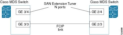
Figure 3-2 provides a sample physical setup in which the virtual N ports are created on ports that are not a part of the FCIP link for which the throughput and latency is measured.
Figure 3-2 N Port Tuning Configuration Physical Example
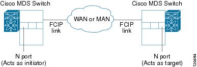
Figure 3-3 provides a sample logical setup in which the virtual N ports are created on ports that are not a part of the FCIP link for which the throughput and latency is measured.
Figure 3-3 Logical Example of N Port Tuning for a FCIP Link
Data Pattern
By default, an all-zero pattern is used as the pattern for data generated by the virtual N ports. You can optionally specify a file as the data pattern to be generated by selecting a data pattern file from one of three locations: the bootflash: directory, the volatile: directory, or the slot0: directory. This option is especially useful when testing compression over FCIP links. You can also use Canterbury corpus or artificial corpus files for benchmarking purposes.
Licensing Requirements for SAN Extension Tuner
To use the SET, you need to obtain the SAN_EXTN_OVER_IP license (see the Cisco Family NX-OS Licensing Guide).
The following table shows the licensing requirements for this feature:
Default Settings
Table 3-1 lists the default settings for tuning parameters.
|
|
|
|---|---|
Configuring the SAN Extension Tuner
This section includes the following topics:
- Tuning the FCIP Link
- Using the SAN Extension Tuner Wizard
- Enabling the Tuner
- Configuring nWWN
- Configuring the Virtual N Port
- Assigning the SCSI Read/Write
- Assigning SCSI Tape Read/Write
- Configuring a Data Pattern
Tuning the FCIP Link
Detailed Steps
To tune the required FCIP link, follow these steps:
Step 1![]() Configure the nWWN for the virtual N ports on the switch.
Configure the nWWN for the virtual N ports on the switch.
Step 2![]() Enable iSCSI on the interfaces on which you want to create the N ports.
Enable iSCSI on the interfaces on which you want to create the N ports.
Step 3![]() Configure the virtual N ports on either side of the FCIP link.
Configure the virtual N ports on either side of the FCIP link.
Step 4![]() Ensure that the virtual N ports are not visible to real initiators in the SAN. You can use zoning (see the Fabric Configuration Guide, Cisco DCNM for SANCisco MDS 9000 Family NX-OS Fabric Configuration Guide) to segregate the real initiators. Ensure that the zoning configuration is set up to allow the virtual N-ports to communicate with each other.
Ensure that the virtual N ports are not visible to real initiators in the SAN. You can use zoning (see the Fabric Configuration Guide, Cisco DCNM for SANCisco MDS 9000 Family NX-OS Fabric Configuration Guide) to segregate the real initiators. Ensure that the zoning configuration is set up to allow the virtual N-ports to communicate with each other.
Step 5![]() Start the SCSI read and write I/Os.
Start the SCSI read and write I/Os.
Step 6![]() Add more N ports (as required) to other Gigabit Ethernet ports in the switch to obtain maximum throughput. One scenario that may require additional N ports is if you use FCIP PortChannels.
Add more N ports (as required) to other Gigabit Ethernet ports in the switch to obtain maximum throughput. One scenario that may require additional N ports is if you use FCIP PortChannels.
Using the SAN Extension Tuner Wizard
You can use the SAN Extension Tuner wizard to perform the these tasks:
Detailed Steps
To tune the required FCIP link using the SAN Extension Tuner Wizard in Cisco DCNM-SAN, follow these steps:
Step 1![]() Right-click a valid FCIP link in the Fabric pane, and then select SAN Extension Tuner from the drop-down list. You can also highlight the link and choose Tools > IP SAN > SAN Extension Tuner.
Right-click a valid FCIP link in the Fabric pane, and then select SAN Extension Tuner from the drop-down list. You can also highlight the link and choose Tools > IP SAN > SAN Extension Tuner.
You see the Select Ethernet Port Pair dialog box.
Step 2![]() Select the Ethernet port pairs that correspond to the FCIP link you want to tune and click Next.
Select the Ethernet port pairs that correspond to the FCIP link you want to tune and click Next.
Note![]() The Ethernet ports you select should be listed as down.
The Ethernet ports you select should be listed as down.
You see the Specify Parameters dialog box.
Step 3![]() Create and activate a new zone to ensure that the virtual N ports are not visible to real initiators in the SAN by clicking Yes to the zone creation dialog box.
Create and activate a new zone to ensure that the virtual N ports are not visible to real initiators in the SAN by clicking Yes to the zone creation dialog box.
Step 4![]() Close the Edit Local Full Zone Database window.
Close the Edit Local Full Zone Database window.
Step 5![]() (Optional) Change the default settings for the transfer data size and the number of concurrent SCSI read and write commands as follows:
(Optional) Change the default settings for the transfer data size and the number of concurrent SCSI read and write commands as follows:
a.![]() Set Transfer Size to the number of bytes that you expect your applications to use over the FCIP link.
Set Transfer Size to the number of bytes that you expect your applications to use over the FCIP link.
b.![]() Set Read I/O to the number of concurrent SCSI read commands you expect your applications to generate over the FCIP link.
Set Read I/O to the number of concurrent SCSI read commands you expect your applications to generate over the FCIP link.
c.![]() Set Write I/O to the number of concurrent outstanding SCSI write commands you expect your applications to generate over the FCIP link.
Set Write I/O to the number of concurrent outstanding SCSI write commands you expect your applications to generate over the FCIP link.
Note![]() There is only one outstanding I/O at a time to the virtual N port that emulates the tape behavior.
There is only one outstanding I/O at a time to the virtual N port that emulates the tape behavior.
d.![]() Check the Use Pattern File check box and select a file that you want to use to set the data pattern that is generated by the SAN extension tuner. See the “Data Pattern” section.
Check the Use Pattern File check box and select a file that you want to use to set the data pattern that is generated by the SAN extension tuner. See the “Data Pattern” section.
You see the Results dialog box.
Step 7![]() Click Start to start the tuner. The tuner sends a continuous stream of traffic until you click Stop.
Click Start to start the tuner. The tuner sends a continuous stream of traffic until you click Stop.
Step 8![]() Click Show to see the latest tuning statistics. You can select this while the tuner is running or after you stop it.
Click Show to see the latest tuning statistics. You can select this while the tuner is running or after you stop it.
Step 9![]() Click Stop to stop the SAN extension tuner.
Click Stop to stop the SAN extension tuner.
Enabling the Tuner
The tuning feature is disabled by default in all switches in the Cisco 9000 Family. When you enable this feature, tuning is globally enabled for the entire switch.
Detailed Steps
To enable the tuning feature, follow these steps:
|
|
|
|
|---|---|---|
Removes the currently applied tuning configuration and disables tuning (default). |
Configuring nWWN
Detailed Steps
To configure the nWWNs for the tuner in this switch, follow these steps:
|
|
|
|
|---|---|---|
Configuring the Virtual N Port
Detailed Steps
To configure the virtual N port for tuning, follow these steps:
Assigning the SCSI Read/Write
You can assign SCSI read and write commands on a one-time basis or on a continuous basis.
Detailed Steps
To assign SCSI read or write commands on a one-time basis, follow these steps:
To generate SCSI read or write commands continuously, follow these steps:
To specify a transfer ready size for a SCSI write command, follow these steps:
Assigning SCSI Tape Read/Write
You can assign SCSI tape read and write commands on a one-time basis or on a continuous basis.
Note![]() There is only one outstanding I/O at a time to the virtual N-port that emulates the tape behavior.
There is only one outstanding I/O at a time to the virtual N-port that emulates the tape behavior.
Detailed Steps
To assign SCSI tape read and or write commands on a one-time basis, follow these steps:
To generate SCSI tape read or write commands continuously, follow these steps:
Configuring a Data Pattern
Detailed Steps
To optionally configure a data pattern for SCSI commands, follow these steps:
Verifying SAN Extension Tuner Configuration
To display SAN extension tuner configuration information, perform one of the following tasks:
Verifying the SAN Extension Tuner Configuration
The show commands display the current SAN extension tuner settings for the Cisco MDS switch (see Examples to ).
Example 3-1 Displays Entries in the FLOGI Database
INTERFACE VSAN FCID PORT NAME NODE NAME ------------------------------------------------------------------------------
iscsi3/4 200 0x050000 12:00:00:00:00:00:00:56 10:00:00:00:00:00:00:00
FCID TYPE PWWN (VENDOR) FC4-TYPE:FEATURE
--------------------------------------------------------------------------
0x020000 N 22:22:22:22:22:22:22:22 scsi-fcp
Additional References
For additional information related to implementing FCIPs, see the following section:
Related Document
|
|
|
|---|---|
Standards
|
|
|
|---|---|
No new or modified standards are supported by this feature, and support for existing standards has not been modified by this feature. |
RFCs
|
|
|
|---|---|
No new or modified RFCs are supported by this feature, and support for existing RFCs has not been modified. |
MIBs
|
|
|
|---|---|
No new or modified MIBs are supported by this feature, and support for existing MIBs has not been modified. |
 Feedback