New and Changed Information
The following table provides an overview of the significant changes up to this current release. The table does not provide an exhaustive list of all changes or of the new features up to this release.
|
Cisco APIC Release Version |
Feature |
Description |
|---|---|---|
| 5.0(x) |
Istio integration (Beta) |
Every cluster now seamlessly comes up with Istio control plane components. For more information, see the section Istio Integration. |
| 4.1(x) | Service account hardening |
Every cluster is now configured with a dedicated administrative account that enables you to control read and write permissions for the whole fabric. For more information, see the section Service Account Hardening. |
|
4.0(1) |
-- |
Added how to drain a node. For more information, see the section Draining a Node. |
|
3.1(1) |
Kubernetes nesting in ESX |
This release enables you to deploy OpFlex base container solutions such as Kubernetes on VMs that are attached onto an ESX VMM. |
|
3.1(1) |
-- |
Added hardware dependency. For more information, see the section Hardware Requirements. |
|
3.0(1) and later |
Service subnet advertisement |
You can configure Cisco Application Centric Infrastructure (ACI) to advertise service subnets externally through a dynamic routing protocol. For more information, see the section Service Subnet Advertisement. |
|
3.0(1) |
Kubernetes on bare-metal servers |
The release support integration of Kubernetes on bare-metal servers into the Cisco Application Centric Infrastructure (ACI). |
Cisco ACI and Kubernetes Integration
Kubernetes is an open source system that automates the deployment, scaling, and managing containers in a network. Beginning with Cisco APIC Release 3.0(1), you can integrate Kubernetes on bare-metal servers into the Cisco Application Centric Infrastructure (ACI).
To integrate Kubernetes with the Cisco ACI, you perform a series of tasks. Some you perform in the network to set up the Cisco Application Policy Infrastructure Controller (APIC); others you perform on the Kubernetes server. Once you have integrated Kubernetes, you can use the Cisco APIC to view Kubernetes in the Cisco ACI.
This document provides the workflow for integrating Kubernetes and specific instructions for setting up the Cisco APIC. However, it is assumed that you are familiar with Kubernetes and containers and can install Kubernetes. Specific instructions for installing Kubernetes are beyond the scope of this document.
Hardware Requirements
This section provides the hardware requirements:
-
Connecting the servers to Gen1 hardware or Cisco Fabric Extenders (FEXes) is not supported and results in a nonworking cluster.
-
The use of symmetric policy-based routing (PBR) feature for load balancing external services requires the use of Cisco Nexus 9300-EX or -FX leaf switches.
For this reason, the Cisco ACI CNI Plug-in is only supported for clusters that are connected to switches of those models.
 Note |
UCS-B is supported as long as the UCS Fabric Interconnects are connected to Cisco Nexus 9300-EX or -FX leaf switches. |
Kubernetes Compatibility Matrix
The following table displays the compatibility matrix for the Kubernetes offerings:
Workflow for Kubernetes Integration
This section provides a high-level description of the tasks required to integrate Kubernetes into the Cisco ACI fabric.
-
Prepare for the integration.
Set up the subnets and VLANs in your network, following instructions in the section " Planning for Kubernetes Integration."
-
Fulfill the prerequisites.
Make sure that you fulfill all the prerequisites in the section "Prerequisites for Integrating Kubernetes with Cisco ACI
-
Provision the Cisco APIC to work with Kubernetes.
Download a provisioning tool, which includes a sample configuration file. Then update the configuration file with information you previously gathered about your network. Then run the provisioning tool with the information about your network. See the section "Provisioning Cisco ACI to Work with Kubernetes."
-
Prepare the Kubernetes node.
Set up networking for the node to support Kubernetes installation. This includes configuring an uplink interface, subinterfaces, and static routes. See the section "Preparing the Kubernetes Nodes."
-
Install Kubernetes and Cisco ACI containers.
Use the appropriate method for your setup. See the section "Installing Kubernetes and Cisco ACI Containers."
-
Verify the integration.
Use the Cisco APIC GUI to verify that Kubernetes has been integrated into the Cisco ACI. See the section "Verifying the Kubernetes Integration."
Planning for Kubernetes Integration
Various network resources are required to provide capabilities to the Kubernetes cluster, including several subnets, and routers.
You need the following subnets:
-
Node subnet: The subnet used for Kubernetes control traffic. It is where the Kubernetes API services are hosted. Make the node subnet a private subnet, and make sure that it has access to the Cisco Application Policy Infrastructure Controller (APIC) management address.
-
Pod subnet: The subnet from which the IP addresses of Kubernetes pods are allocated. Make the pod subnet a private subnet.
Note
This subnet specifies the starting address for the IP pool that is used to allocate IP addresses to pods and your Cisco ACI bridge domain IP. For example, if you define it as 192.168.255.254/16, it is a valid configuration from a Cisco ACI perspective. However, your containers will not get an IP address because there are no free IPs after 192.168.255.254 in this subnet. We suggest to always use the first IP address in the POD subnet. In this example: 192.168.0.1/16.
-
Node service subnet: The subnet used for internal routing of load-balanced service traffic. Make the node service subnet a private subnet.
Note
Similarly to the Pod subnet note, configure it with the first IP in the subnet.
-
External service subnets: Pools from which load-balanced services are allocated as externally accessible service IPs.
The externally accessible service IPs could be globally routable. Configure the next-hop router to send traffic to these IPs to the fabric. There are two such pools: One is used for dynamically allocated IPs and the other is available for services to request a specific fixed external IP.
You need the following VLANS for local fabric use:
-
Node VLAN: The VLAN used by the physical domain for Kubernetes nodes.
-
Service VLAN: The VLAN used for delivery of load-balanced service traffic.
-
Infra VLAN: The infra VLAN used by the Cisco ACI fabric.
In addition to providing network resources, read and understand the guidelines in the knowledge base article Cisco ACI and OpFlex Connectivity for Orchestrators.
Prerequisites for Integrating Kubernetes with Cisco ACI
The following are required before you can integrate Kubernetes with the Cisco ACI fabric:
-
A working Cisco ACI installation
-
An attachable entity profile (AEP) set up with interfaces that are desired for the Kubernetes deployment
-
A Layer 3 Outside connection, along with a Layer 3 external network to serve as external access
-
Virtual routing and forwarding (VRF) configured.
Note
The VRF and L3Out in Cisco ACI that are used to provide outside connectivity to Kubernetes external services can be in any tenant. The most common usage is to put the VRF and L3Out in the common tenant or in a tenant that is dedicated to the Kubernetes cluster. You can also have separate VRFs, one for the Kubernetes bridge domains and one for the L3Out, and you can configure route leaking between them.
-
Any required route reflector configuration for the Cisco ACI fabric
-
A next-hop router that is connected to the Layer 3 external network capable of doing appropriate external access and configured with the required routes
In addition, the Kubernetes cluster must be up through the fabric-connected interface on all the hosts. The default route should be pointing to the ACI node subnet bridge domain. This is not mandatory, but it simplifies the routing configuration on the hosts and is the recommend configuration. If you choose not to follow this design, all Kubernetes related traffic must go through the fabric.
Provisioning Cisco ACI to Work with Kubernetes
Use the acc_provision tool to provision the fabric for the Kubernetes VMM domain and generate a .yaml file that Kubernetes uses to deploy the required Cisco Application Centric Infrastructure (ACI) container components.
ACI CNI in nested mode is only supported with VMM-integrated VMware (with dVS).
Procedure
| Step 1 |
Download the provisioning tool from cisco.com.
|
||||
| Step 2 |
Generate a sample configuration file that you can edit. Example:The command generates a configuration file that looks like the following example:
|
||||
| Step 3 |
Edit and save the sample configuration file, providing information from your network. |
||||
| Step 4 |
Obtain the package which provides acc-provision. |
||||
| Step 5 |
Provision the Cisco ACI fabric. Example:This command generates the file aci-containers.yaml that you use after installing Kubernetes. It also creates the files user-[system id].key and user-[system id].crt that contain the certificate used to access Cisco APIC. Save these files in case you change the configuration later and want to avoid disrupting a running cluster because of a key change. This step also generates a tar.gz file called aci-containers.yaml.tar.gz that contains all the .yaml resources in aci-containers.yaml required by the Cisco ACI Container Network Interface (CNI) plug-in operator.
|
||||
| Step 6 |
(Optional): Advanced optional parameters can be configured to adjust to custom parameters other than the ACI default values or base provisioning assumptions:
|
Preparing the Kubernetes Nodes
After you provision Cisco Application Centric Infrastructure (ACI), you prepare networking for the Kubernetes nodes.
Procedure
| Step 1 |
Configure your uplink interface with NIC bonding or not, depending on how your AEP is configured. Set the MTU on this interface to at least 1600, preferably 9000.
|
||||
| Step 2 |
Create a subinterface on your uplink interface on your infra VLAN. Configure this subinterface to obtain an IP address using DHCP. Set the MTU on this interface to 1600. |
||||
| Step 3 |
Configure a static route for the multicast subnet 224.0.0.0/4 through the uplink interface used for VXLAN traffic. |
||||
| Step 4 |
Create a subinterface on your uplink interface on your node VLAN. For example, which is called kubeapi_vlan in the configuration file. Configure an IP address on this interface in your node subnet. Then set this interface and the corresponding node subnet router as the default route for the node.
|
||||
| Step 5 |
Create the /etc/dhcp/dhclient-eth0.4093.conf file with the following content, inserting the MAC address of the Ethernet interface for each server on the first line of the file:
Example:The network interface on the infra VLAN requests a DHCP address from the Cisco Cisco Application Policy Infrastructure Controller (APIC) infrastructure network for OpFlex communication. Make sure that the server has a client configuration for this interface to receive all the correct DHCP options with the lease. If you need information on how to configure a VPC interface for the Kubernetes servers, see "Manually Configure the Host vPC" in the Cisco ACI with OpenStack OpFlex Deployment Guide for Red Hat on Cisco.com.
|
||||
| Step 6 |
If you have a separate management interface for the node being configured, configure any static routes that you need to access your management network on the management interface. |
||||
| Step 7 |
Ensure that Open vSwitch (OVS) is not running on the node. |
||||
| Step 8 |
Informational: Here is an example of the interface configuration (/etc/network/interfaces): |
||||
| Step 9 |
Tune the igmp_max_memberships kernel parameter. The Cisco ACI Container Network Interface (CNI) plug-in gives you the flexibility to place Namespaces, Deployment, and PODs into dedicated endpoint groups (EPGs). To ensure that Broadcast, Unknown Unicast and Multicast traffic (BUM) is not flooded to all the EPGs, Cisco ACI allocates a dedicated multicast address for BUM traffic replication for every EPG that is created. Recent kernel versions set the default for the igmp_max_memberships parameter to 20, limiting the maximum number of EPGs that can be utilized to 20. To have more than 20 EPGs, you can increase the igmp_max_memberships with the following steps:
|
Installing Kubernetes and Cisco ACI Containers
After you provision Cisco ACI and prepare the Kubernetes nodes, you can install Kubernetes and ACI containers. You can use any installation method you choose appropriate to your environment. This procedure provides guidance and high-level instruction for installation; for details, consult Kubernetes documentation.
When installing Kubernetes, ensure that the API server is bound to the IP addresses on the node subnet and not to management or other IP addresses. Issues with node routing table configuration and API server advertisement addresses are the most common problems during installation. Should problems occur, check these first.
Install Kubernetes so that it is configured to use a Container Network Interface (CNI) plug-in, but do not install a specific CNI plug-in configuration through your installer. Instead, deploy the CNI plug-in.
Run the acc-provision command as detailed above, in the Provisioning Cisco ACI to Work with Kubernetes section. After running acc-provision, it will output ACI-CNI deployment yaml (referred to as aci-containers.yaml in the document)
which refers to the ACI-CNI container images. These container images are also provided as a package. With reference to the
example below, dist-generics-5.2.3.5.tar.gz. For the detailed procedure as to how to obtain the packages from Cisco.com, see the Provisioning Cisco ACI to Work with Kubernetes procedure.
Example:
openshift_installer_4.11-5.2.3.5-2.src.tar.gz      29-Jan-2023	164.26 MB

Debian package for ACI CNI Tools 		    26-Jan-2023	11.72 MB
(acc-provision and acikubectl)
dist-debs-5.2.3.5.tar.gz

ACI CNI Container Images				26-Jan-2023	2783.95 MB
dist-generics-5.2.3.5.tar.gz

RPM package for ACI CNI Tools (acc-provision	26-Jan-2023 	6.95 MB
and acikubectl)
dist-rpms-5.2.3.5.tar.gz
If you are using these images from the package, upload each of them to the local registry of each Kubernetes node using the docker load command.
If the cluster has access to the external world, there is an easier option to obtain the ACI-CNI container images. All released container images are always posted on quay.io/noiro. You can point to these images by setting the following configuration in the acc-provision input file:
registry:
  image_prefix: quay.io/noiro
Note |
Instead of quay.io, the images can also be loaded into a local registry, and that local registry can be specified in the above configuration. |
Procedure
|
Install the CNI plug-in using the following command: You can perform the command wherever you have kubectl set up, generally from a Kubernetes master node. The command installs the following:
|
Verifying the Kubernetes Integration
After you have performed the previous steps, you can verify the integration in the Cisco APIC GUI. The integration creates a tenant, three EPGs, and a VMM domain.
Procedure
| Step 1 |
Log in to the Cisco APIC. |
| Step 2 |
Go to . The tenant should have the name that you specified in the configuration file that you edited and used in installing Kubernetes and the ACI containers. |
| Step 3 |
In the tenant navigation pane, expand the following: . If the cluster has the You should see three folders inside the Application EPGs folder:
|
| Step 4 |
In the tenant navigation pane, expand the Networking and Bridge Domains folders. You should see two bridge domains:
|
| Step 5 |
If you deploy Kubernetes with a load balancer, go to , expand L4-L7 Services, and perform the following steps:
|
| Step 6 |
Go to . |
| Step 7 |
In the Inventory navigation pane, expand the Kubernetes folder. You should see that a VMM domain, with the name that you provided in the configuration file, is created and that the domain contains a folder called Nodes and a folder called Namespaces. |
Unprovisioning Kubernetes from the ACI Fabric
This section describes how to uprovision Kubernetes from the ACI fabric.
Procedure
|
To unprovision, enter the following command: Example:This command unprovisions the resources that have been allocated for this Kubernetes. This also deletes the tenant. If you are using a shared tenant with other clusters, the code ensures that the shared tenant is not deleted. |
Uninstalling the CNI Plug-In
This section describes how to uninstall the CNI plug-in.
Procedure
|
Uninstall the CNI plug-in using the following command: Example: |
Using Policy
Network Policy and EPGs
The Cisco ACI and Kubernetes integration was designed to offer a highly flexible approach to policy. It was based on two premises: that Kubernetes templates not need to change when they run on Cisco ACI, and that developers not be forced to implement any APIC configuration to launch new applications. At the same time, the solution optionally exposes Cisco ACI EPGs and contacts to Kubernetes users if they choose to leverage them for application isolation.
By default, Cisco plug-ins create an EPG and a bridge domain in APIC for the entire Kubernetes cluster. All pods by default are attached to the new EPG, has no special properties. The container team or the network team do not need to take any further action for a fully functional Kubernetes cluster—as one might find in a public cloud environment. Also, security enforcement can occur based on usage of the Kubernetes NetworkPolicy API. NetworkPolicy objects are transparently mapped into Cisco ACI and enforced for containers within the same EPG and between EPGs.
The following is an example of NetworkPolicy in Kubernetes:
apiVersion: networking.k8s.io/v1
kind: NetworkPolicy
metadata:
  name: test-network-policy
  namespace: default
spec:
  podSelector:
    matchLabels:
      role: db
  ingress:
  - from:
    - namespaceSelector:
        matchLabels:
          project: myproject
    - podSelector:
        matchLabels:
          role: frontend
    ports:
    - protocol: TCP
      port: 6379
However, in many cases, you may want to leverage EPGs and contracts in a more flexible way to define policy. You can create additional EPGs and contracts either directly or through the Cisco APIC.
To move namespaces, deployments, replication controllers, or pods into these EPGs, a Kubernetes user simply applies an annotation to any of these objects specifying the application profile and EPG. The running pods automatically shift to the new EPG, and any configured contracts are applied. In this model, it is still possible to use Kubernetes NetworkPolicy, which is honored regardless of how pods are mapped to EPGs.
Mapping to Cisco APIC
Each Kubernetes cluster is represented by a tenant within Cisco APIC. By default, all pods are placed in a single EPG created automatically by the plug-ins. However, it is possible to map a namespace, deployment, or pod to a specific application profile and EPG in Kubernetes through Kubernetes annotations.
While this is a highly flexible model, there are three typical ways to use it:
-
EPG=Kubernetes Cluster—This is the default behavior and provides the simplest solution. All pods are placed in a single EPG, kube-default.
-
EPG=Namespace—This approach can be used to add namespace isolation to Kubernetes. While Kubernetes does not dictate network isolation between namespaces, many users may find this desirable. Mapping EPGs to namespaces accomplishes this isolation.
-
EPG=Deployment—A Kubernetes deployment represents a replicated set of pods for a microservice. You can put that set of pods in its EPG as a means of isolating specific microservices and then use contracts between them.
Creating and Mapping an EPG
Use this procedure to create and EPG, using annotations to map namespaces or deployments into it.
For information about EPGs and bridge domains, see the Cisco APIC Basic Configuration Guide.
Note |
Beginning with Cisco APIC Release 5.2(1), a fault is raised against the VMM domain on APIC, if annotated objects are not resolved
in a new EPG. The description of the fault includes, namespace/ deployment/ pod details. The next correct annotation clears
the fault instances on APIC. The corresponding MO is |
Procedure
| Step 1 |
Log in to Cisco APIC. |
| Step 2 |
Create the EPG and add it to the bridge domain kube-pod-bd. |
| Step 3 |
Attach the EPG to the VMM domain. |
| Step 4 |
Configure the EPG to consume contracts in the Kubernetes tenant:
|
| Step 5 |
Configure the EPG to consume contracts in the common tenant: Consume: kube-l3out-allow-all (optional) |
| Step 6 |
Create any contracts you need for your application and provide and consume them as needed. |
| Step 7 |
Apply annotations to the namespaces or deployments. You can apply annotations in three ways:
|
The acikubectl Command
The acikubectl command is a command-line utility that provides an abbreviated way to manage Cisco ACI policies for Kubernetes objects and annotations. It also enables you to debug the system and collect logs.
The acikubectl command includes a --help option that displays descriptions of the command's supported syntax and options, as seen in the following example:
acikubectl -–help

Available Commands:
  debug       Commands to help diagnose problems with ACI containers
  get         Get a value
  help        Help about any command
  set         Set a value
  version     Print the client and server versions for the current context acikubectl version
Load Balancing External Services
For Kubernetes services that are exposed externally and need to be load balanced, Kubernetes does not handle the provisioning of the load balancing. It is expected that the load balancing network function is implemented separately. For these services, Cisco ACI takes advantage of the symmetric policy-based routing (PBR) feature available in the Cisco Nexus 9300-EX or FX leaf switches in ACI mode.
On ingress, incoming traffic to an externally exposed service is redirected by PBR to one of the Kubernetes nodes that hosts at least one pod for that particular service. Each node hosts a special service endpoint that handles the traffic for all external services hosted for that endpoint. Traffic that reaches the service endpoint is not rewritten by the fabric, so it retains its original destination IP address. It is not expected that the Kubernetes pods handle traffic that is sent to the service IP address, so Cisco ACI performs the necessary network address translation (NAT).
If a Kubernetes worker node contains more than one IP pod for a particular service, the traffic is load balanced a second time across all the local pods for that service.
A simplified view of the Cisco ACI policy model required for the north-south load balancer is shown in the following illustration.
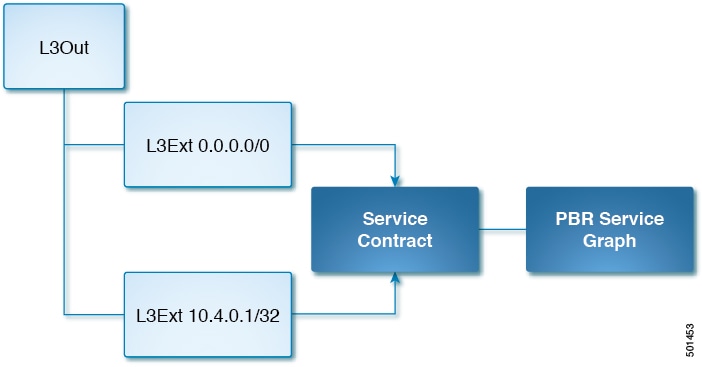
In the example, service IP 10.4.0.1 is exposed as an external service. It is presented as a /32 Layer 3 external network. This network provides a contract that is consumed by the default /0 Layer 3 external network. Traffic that comes into the fabric from the outside hits this contract and is redirected by the service graph to the correct set of Kubernetes service endpoints.
The Cisco ACI Kubernetes integration components are responsible for automatically writing the Cisco ACI policy that implements the external service into Cisco ACI.
Load Balancing External Services Across Multiple L3Out
ACI CNI supports load balancing external services across multiple L3Outs. However, the service contract must be configured
manually on the external EPG in the consumer direction. Also, if the L3Out is in a different tenant and/or VRF, then you need
to change the contract scope accordingly. This can be done by annotating the service with "opflex.cisco.com/ext_service_contract_scope=<scope>". If the ext_service_contract_scope annotation is not set, or if it set as an empty string (i.e. opflex.cisco.com/ext_service_contract_scope=””) then, the contract scope is set to context (VRF). Setting any scope other than context will also set the "import-security"
attribute for the subnet associated with the External EPG that is consuming the contract. This allows the service to be reachable
across the VRFs.
Istio Integration
Istio is an infrastructure layer that facilitates service-to-service communications. It makes it easy to create a network of deployed services with load balancing, service-to-service authentication, monitoring, and more, with almost no code changes in application code.
Beginning in Cisco Application Policy Infrastructure Controller (APIC) release 5.0(1), Istio is integrated with Cisco Application Centric Infrastructure (ACI) Container Network Interface (CNI) plug-in. By default, the Istio control plan components are installed with a clearn isolation from the rest of the Cisco ACI CNI plug-in or user application pods.
Istio installation can be disabled by setting a configuration parameter in the acc-provision-input file and generating the deployment file, as shown in the following example:
install-istio: False Draining a Node
This section describes how to drain the pods on a node.
Procedure
| Step 1 |
Drain the node: Example: |
||
| Step 2 |
After the drain is finished, scale the controller down to 0 replicas: Example: |
||
| Step 3 |
Remove the old annotations from the node by editing the node description and remove the opflex.cisco.com annotations and save the changes: Example: |
||
| Step 4 |
Find and delete the hostagent pod for the drained node: Example:
|
||
| Step 5 |
Bring the controller up again: Example: |
||
| Step 6 |
Bring back the node: Example: |
||
| Step 7 |
Verify annotations are present and that the hostagent pod is running: Example: |
Service Subnet Advertisement
By default, service subnets are not advertised externally, requiring that external routers be configured with static routes. However, you can configure Cisco Application Centric Infrastructure (ACI) to advertise the service subnets through a dynamic routing protocol.
To configure and verify service subnet advertisement, complete the procedures in this section.
Configuring Service Subnet Advertisement
Complete the following steps to configure service subnet advertisement.
Note |
Perform this procedure for all border leafs that are required to advertise the external subnets. |
Procedure
| Step 1 |
Add routes to null to the subnets: |
| Step 2 |
Create match rules for the route map and add the subnet.
|
| Step 3 |
Create a route map for the L3 Out, add a context to it, and choose the match rules.
|
What to do next
Verify that the external routers have been configured with the external routes. See the section Verifying Service Subnet Advertisement.
Verifying Service Subnet Advertisement
Use NX-OS style CLI to verify that the external routers have been configured with the external routes. Perform the commands for each for the border leafs.
Before you begin
fab2-apic1# fabric 203 show ip route vrf common:k8s | grep null0 -B1
10.3.0.1/24, ubest/mbest: 1/0
    *via , null0, [1/0], 04:31:23, static
10.4.0.1/24, ubest/mbest: 1/0
    *via , null0, [1/0], 04:31:23, static
Procedure
| Step 1 |
Check the route maps applied to your dynamic routing protocol that permits the advertisement of the subnets. |
| Step 2 |
Find the specific route for each of the nodes, looking for entries that match the name of the match rule: Example:In the example, |
| Step 3 |
Verify that the IP addresses are correct for each of the nodes: Example: |
Service Account Hardening
Every time that you create a cluster, a dedicated user account is automatically created in Cisco Application Policy Infrastructure Controller (APIC). This account is an administrative account with read and write permissions for the whole fabric.
Read and write permissions at the fabric level could be a security concern in case of multitenant fabrics where you do not want the cluster administrator to have administrative access to the Cisco Application Centric Infrastructure (ACI) fabric.
You can modify the dedicated user account limits and permissions. The level and scope of permission that is required for the cluster account depend on the location of the networking resources:
(The networking resources include the bridge domain, virtual routing and forwarding (VRF), and Layer 3 outside (L3Out).)
-
When cluster resources are in the cluster dedicated tenant, the account needs read and write access to the cluster tenant and the cluster container domain.
-
When cluster resources are in the common tenant, the account needs read and write access to the common tenant, the cluster tenant, and the cluster container domain.
Checking the Current Administrative Privileges
Complete the following procedure to see the current administrator privileges for the Cisco Application Centric Infrastructure (ACI) fabric.
Procedure
| Step 1 |
Log in to Cisco Application Policy Infrastructure Controller (APIC). |
| Step 2 |
Go to . |
| Step 3 |
Click the username associated with your cluster. |
| Step 4 |
Scroll to the security domain and verify the following:
|
Modifying Administrative Account Permissions
After you configure the fabric, you can see a new tenant and Cisco Application Centric Infrastructure (ACI) user. Its name is equal to the system_id parameter specified in the Cisco ACI Container Network Interface (CNI) configuration file. Complete the following procedure to modify administrative permissions:
Note |
This procedure works whether cluster resources are in the same tenant or when virtual routing and forwarding (VRF) and Layer 3 Outside (L3Out) are in the common tenant. However, if VRF and L3Out are in the common tenant, you must give write permission to the common tenant In Step 3. |
Procedure
| Step 1 |
Log in to the Cisco Application Policy Infrastructure Controller (APIC). |
| Step 2 |
Create a new security domain by completing the following steps: |
| Step 3 |
Go to and complete the following steps: |
| Step 4 |
Create a custom role-based access control (RBAC) rule to allow the container account to write information into the container domain by completing the following steps: |
| Step 5 |
Map the security domain to the cluster tenant by completing the following steps:
|
Troubleshooting Kubernetes Integration
This section contains instructions for troubleshooting the Kubernetes integration with Cisco ACI.
Troubleshooting Checklist
This section contains a checklist to troubleshoot problems that occur after you integrate Kubernetes with Cisco ACI.
Procedure
| Step 1 |
Check for faults on the fabric and resolve any that are relevant. |
| Step 2 |
Check that the API server advertisement addresses use the node subnet, and that the nodes are configured to route all Kubernetes subnets over the node uplink. Typically, the API server advertisement address is pulled from the default route on the node during installation. If you are putting the default route on a different network than the node uplink interfaces, you should do so—in addition to configuring the subnets from the planning process and the cluster IP subnet used internally for Kubernetes. |
| Step 3 |
Check the logs for the container aci-containers-controller for errors using the following command on the Kubernetes master node: acikubectl debug logs controller acc |
| Step 4 |
Check these node-specific logs for errors using the following commands on the Kubernetes master node:
|
Troubleshooting Specific Problems
Collecting and Exporting Logs
Procedure
|
Enter the following command to collect and export Kubernetes logs: acikubectl debug cluster-report -o cluster-report.tar.gz |
Troubleshooting External Connectivity
Procedure
| Step 1 |
Check configuration of the next-hop router. |
| Step 2 |
When contracts are not enforced by the fabric, you cannot access external services from the next-hop router. You can access external services from an IP address that is not in the subnet configured on the next-hop router interface. |
Troubleshooting POD EPG Communication
Follow the instructions in this section if communication between two pod EPGs is not working.
Procedure
| Step 1 |
Check the contracts between the pod EPGs. |
| Step 2 |
Verify that there is a contract that allows ARP traffic. All pods are in the same subnet so Address Resolution Protocol (ARP) is required. |
Troubleshooting Endpoint Discovery
If an endpoint is not automatically discovered, either EPG does not exist or mapping of the annotation to EPG is not in place. Follow the instructions in this section to troubleshoot the problem.
Procedure
| Step 1 |
Ensure that the EPG name, tenant, and application are spelled correctly. |
| Step 2 |
Make sure that the VMM domain is mapped to an EPG. |
Troubleshooting Pod Health Check
Follow the instructions in this section if the pod health check doesn't work.
Procedure
|
Ensure that the health check contract exists between the pod EPG and the node EPG. |
Troubleshooting aci-containers-host
Follow the instructions in this section if the mcast-daemon inside aci-containers-host fails to start.
Procedure
|
Check the mcast-daemon log messages: Example:If the following error message is present, Fatal error: open: Address family not supported by protocol, ensure that IPv6 support is enabled in the kernel. IPv6 must be enabled in the kernel for the mcast-daemon to start. |
Contacting Support
If you need help with troubleshooting problems, generate a cluster report file and contact Cisco TAC for support.
 Feedback