|
Step 1
|
On the menu bar, choose .
|
|
Step 2
|
In the Navigation pane, right-click Interfaces and choose Configure Interface, PC and VPC.
|
|
Step 3
|
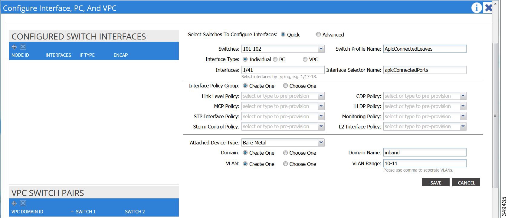
In the
Configure Interface, PC, and VPC dialog box, to
configure switch ports connected to APICs, perform the following actions:
-
Click the
large
+ icon next to the switch diagram to create a new
profile and configure VLANs for the APIC.
-
From the
Switches field drop-down list, check the check boxes
for the switches to which the APICs are connected. (leaf1 and leaf2).
-
In the
Switch Profile Name field, enter a name for the
profile (apicConnectedLeaves).
-
Click the
+ icon to configure the ports.
A dialog
box similar to the following image is displayed for the user to enter the
content:

-
Verify
that in the
Interface Type area, the
Individual radio button is selected.
-
In the
Interfaces field, enter the ports to which APICs are
connected.
-
In the
Interface Selector Name field, enter the name of the
port profile (apicConnectedPorts).
-
In the
Interface Policy Group field, click the
Create One radio button.
-
In the
Attached Device Type field, choose the appropriate
device type to configure the domain (Bare Metal).
-
In the
Domain field, click the
Create One radio button.
-
In the
Domain Name field, enter the domain name.
(inband)
-
In the
VLAN field, choose the
Create One radio button.
-
In the
VLAN Range field, enter the VLAN range. Click
Save, and click
Save again. Click
Submit.
|
|
Step 4
|
In the
Navigation
pane, right-click
Switch
Policies and choose
Configure
Interface, PC and VPC.
|
|
Step 5
|
In the
Configure Interface, PC, and VPC dialog box, perform
the following actions:
-
Click the
large
+ icon next to the switch diagram to create a new
profile and configure VLANs for the server.
-
In the
Switches field, from drop-down list, check the check
boxes for the switches to which the servers are connected. (leaf1).
-
In the
Switch Profile Name field, enter a name for the
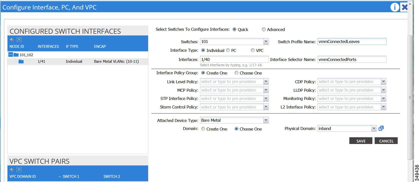
profile (vmmConnectedLeaves).
-
Click the
+ icon to configure the ports.
A dialog
box similar to the following image is displayed for the user to enter the
content:

-
Verify
that in the
Interface Type area, the
Individual radio button is selected.
-
In the
Interfaces field, enter the ports to which the
servers are connected (1/40).
-
In the
Interface Selector Name field, enter the name of the
port profile.
-
In the
Interface Policy Group field, click the
Create One radio button.
-
In the
Attached Device Type field, choose the appropriate
device type to configure the domain (Bare Metal).
-
In the
Domain field, from the drop-down list click the
Choose One radio button
-
From the
Physical Domain drop-down list, choose the domain
created earlier.
-
In the
Domain Name field, enter the domain name.
-
Click
Save, and click
Save again.
|
|
Step 6
|
In the
Configure Interface, PC, and VPC dialog box, click
Submit.
|
|
Step 7
|
On the menu
bar, click
. In the
Navigation pane, expand
to configure the bridge domain on the in-band
connection.
|
|
Step 8
|
Expand the
in-band bridge domain (inb). Right-click
Subnets. Click
Create
Subnet and perform the following actions to configure the in-band
gateway:
-
In the
Create Subnet dialog box, in the
Gateway IP field, enter the in-band management
gateway IP address and mask.
-
Click
Submit.
|
|
Step 9
|
In the
Navigation pane, expand
. Right-click
Node
Management EPGs and choose
Create
In-Band Management EPG. Perform the following actions to set the
VLAN on the in-band EPG used to communicate with the APIC:
-
In the
Name field, enter the in-band management EPG name.
-
In the
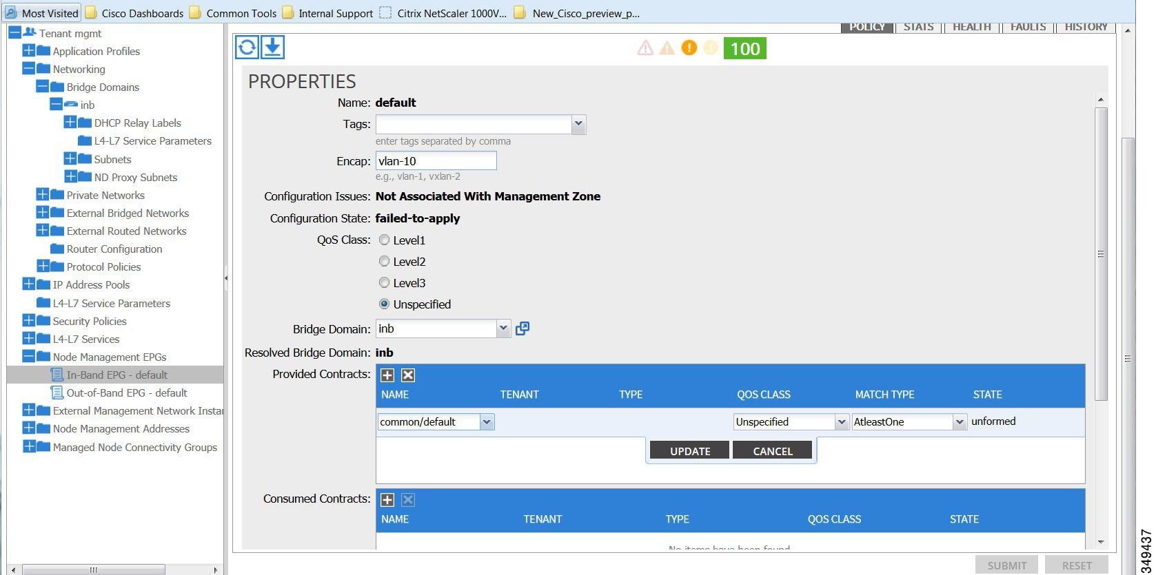
Encap field, enter the VLAN (vlan-10).
-
From the
Bridge Domain drop-down field, choose the bridge
domain. Click
Submit.
-
In the
Navigation pane, choose the newly created in-band
EPG.
-
Expand
Provided Contracts. In the
Name field, from the drop-down list, choose the
default contract to enable EPG to provide the default contract that will be
consumed by the EPGs on which the VMM servers are located.
-
Click
Update, and click
Submit.
A dialog box
similar to the following image is displayed:

|
|
Step 10
|
In the
Navigation pane, right-click
Node
Management Addresses and click
Create
Node Management Addresses, and perform the following actions to
configure the IP addresses to be assigned to APIC controllers in the fabric:
-
In the
Create Node Management Addresses dialog box, in the
Policy Name field, enter the policy name (apicInb).
-
In the
Nodes field,
Select column, check the check boxes for the nodes
that will be part of this fabric (apic1, apic2, apic3).
-
In the
Config field, check the
In-Band Addresses check box.
-
In the
Node Range fields, enter the range.
-
In the
In-Band IP Addresses area, in the
In-Band Management EPG field, from the drop-down
list, choose default. This associates the default in-band Management EPG.
-
In the
In-Band IP Addresses and
Gateway fields, enter the IPv4 or IPv6 addresses as
desired.
-
Click
Submit. The IP addresses for the APICs are now
configured.
|
|
Step 11
|
In the
Navigation pane, right-click
Node
Management Addresses. Click
Create
Node Management Addresses, and perform the following actions to
configure the IP addresses for the leaf and spine switches in the fabric:
-
In the
Create Node Management Addresses dialog box, in the
Policy Name field, enter the policy name
(switchInb).
-
In the
Nodes field,
Select column, check the check boxes next to the
nodes that will be part of this fabric (leaf1, leaf2, spine1, spine2).
-
In the
Config field, click the
In-Band Addresses checkbox.
-
In the
Node Range fields, enter the range.
-
In the
In-Band IP Addresses area, in the
In-Band Management EPG field, from the drop-down
list, choose default. The default in-band management EPG is now associated.
-
In the
In-Band IP Addresses and
Gateway fields, enter the IPv4 or IPv6 addresses as
desired.
-
Click
Submit. In the
Confirm dialog box, click
Yes. The IP addresses for the leaf and spine
switches are now configured.
|
|
Step 12
|
In the
Navigation pane, under
Node
Management Addresses, click the APIC policy name (apicInb) to
verify the configurations. In the
Work pane, the IP addresses assigned to various nodes
are displayed.
|
|
Step 13
|
In the
Navigation pane, under
Node
Management Addresses, click the switches policy name (switchInb).
In the
Work pane, the IP addresses that are assigned to
switches and the gateway addresses they are using are displayed.
|
Note
|
You can make out-of-band management access the default management connectivity mode for the APIC server by clicking . Then on the Connectivity Preferences page, click inband.
|
|


 Feedback