About Fabric Initialization
You can build a fabric by adding switches to be managed by the APIC and then validating the steps using the GUI, the CLI, or the API.
 Note |
Before you can build a fabric, you must have already created an APIC cluster over the out-of-band network. |
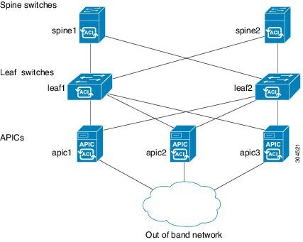
Fabric Topology (Example)
An example of a fabric topology is as follows:
-
Two spine switches (spine1, spine2)
-
Two leaf switches (leaf1, leaf2)
-
Three instances of APIC (apic1, apic2, apic3)
The following figure shows an example of a fabric topology.
Connections: Fabric Topology
An example of the connection details for the fabric topology is as follows:
| Name | Connection Details |
|---|---|
|
leaf1 |
eth1/1 = apic1 (eth2/1) eth1/2 = apic2 (eth2/1) eth1/3 = apic3 (eth2/1) eth1/49 = spine1 (eth5/1) eth1/50 = spine2 (eth5/2) |
|
leaf2 |
eth1/1 = apic1 (eth 2/2) eth1/2 = apic2 (eth 2/2) eth1/3 = apic3 (eth 2/2) eth1/49 = spine2 (eth5/1) eth1/50 = spine1 (eth5/2) |
|
spine1 |
eth5/1 = leaf1 (eth1/49) eth5/2 = leaf2 (eth1/50) |
|
spine2 |
eth5/1 = leaf2 (eth1/49) eth5/2 = leaf1 (eth1/50) |
Multi-Tier Fabric Topology (Example)
3-tier Core-Aggregation-Access architectures are common in data center network topologies. As of the Cisco APIC Release 4.1(1), you can create a multi-tier ACI fabric topology that corresponds to the Core-Aggregation-Access architecture, thus mitigating the need to upgrade costly components such as rack space or cabling. The addition of a tier-2 leaf layer makes this topology possible. The tier-2 leaf layer supports connectivity to hosts or servers on the downlink ports and connectivity to the leaf layer (aggregation) on the uplink ports.
In the multi-tier topology, the leaf switches initially have uplink connectivity to the spine switches and downlink connectivity to the tier-2 leaf switches. To make the entire topology an ACI fabric, all ports on the leaf switches connecting to tier-2 leaf fabric ports must be configured as fabric ports (if not already using the default fabric ports). After APIC discovers the tier-2 leaf switch, you can change the downlink port on the tier-2 leaf to a fabric port and connect to an uplink port on the middle layer leaf.
The following figure shows an example of a multi-tier fabric topology.
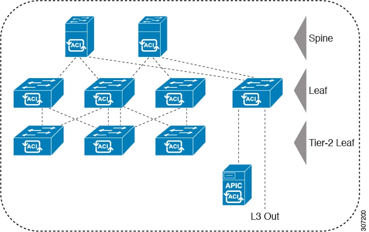
While the topology in the above image shows the Cisco APIC and L3Out/EPG connected to the leaf aggregation layer, the tier-2 leaf access layer also supports connectivity to APICs and L3Out/EPGs.
Note |
Only Cisco Nexus 9000 Series switches with model numbers that end in EX, and later are supported as tier-2 leaf switches and as leaf switches, if there are tier-2 leaf switches attached to them. See the table below. Tier-2 leaf switches attached to remote leaf switches are not supported. |
|
Switch |
Downlink Port Speeds (as tier-2 leaf) |
Uplink Port Speeds (as tier 2 leaf) |
Downlink Fabric Port Speeds (as tier-1 leaf) |
|---|---|---|---|
|
Nexus 93180YC-EX |
48 x 1/10/25-Gbps |
48 x 10/25-Gbp 6 x 40/100-Gbps |
48 x 10/25-Gbps 6 x 40/100-Gbps |
|
Nexus 93108TC-EX |
48 x 100M/1/10GBASE-T |
6 x 40/100-Gbps |
N/A |
|
N9K-9348GC-FXP |
48 x 100M/1G BASE-T 4 x 10/25-Gbps |
4 x 10/25-Gbps 2 x 40/100-Gbps |
N/A |
|
N9K-9358-FXP |
8 x 100M/1G BASE-T 4 x 10/25-Gbps |
4 x 10/25-Gbps 2 x 40/100-Gbps |
N/A |
|
N9K-93180YC-FX |
48 x 1/10/25-Gbps |
48 x 10/25-Gbps 6 x 40/100-Gbps |
48 x 10/25-Gbps 6 x 40/100-Gbps |
|
N9K-93108TC-FX |
48 x 100M/1G BASE-T 4 x 10/25-Gbps |
4 x 10/25-Gbps 2 x 40/100-Gbps |
4 x 10/25-Gbps 2 x 40/100-Gbps |
|
N9K-93240YC-FX2 |
N/A |
N/A |
48 x 10/25-Gbps fiber ports 12 x 40/100-Gbps |
|
N9K-C9336C-FX2 |
1-34 x 40/100-Gbps |
36 x 40/100-Gbps |
36 x 40/100-Gbps |
 Feedback