CGS 2520 Switch Command Reference, 12.2(53)EX
Bias-Free Language
The documentation set for this product strives to use bias-free language. For the purposes of this documentation set, bias-free is defined as language that does not imply discrimination based on age, disability, gender, racial identity, ethnic identity, sexual orientation, socioeconomic status, and intersectionality. Exceptions may be present in the documentation due to language that is hardcoded in the user interfaces of the product software, language used based on RFP documentation, or language that is used by a referenced third-party product. Learn more about how Cisco is using Inclusive Language.
- Updated:
- July 19, 2010
Chapter: Cisco IOS Commands - aaa through reserved-only
- aaa accounting dot1x
- aaa authentication dot1x
- action
- alarm contact
- alarm facility fcs-hysteresis
- alarm facility power-supply
- alarm facility temperature
- alarm profile (global configuration)
- alarm profile (interface configuration)
- alarm relay-mode
- archive download-sw
- archive tar
- archive upload-sw
- arp access-list
- authentication control-direction
- authentication critical recovery delay
- authentication event
- authentication fallback
- authentication host-mode
- authentication mac-move permit
- authentication open
- authentication order
- authentication periodic
- authentication port-control
- authentication priority
- authentication timer
- authentication violation
- bandwidth
- boot config-file
- boot enable-break
- boot helper
- boot helper-config-file
- boot manual
- boot private-config-file
- boot system
- channel-group
- channel-protocol
- class
- class-map
- clear ip arp inspection log
- clear ip arp inspection statistics
- clear ip dhcp snooping
- clear ipc
- clear ipv6 dhcp conflict
- clear l2protocol-tunnel counters
- clear lacp
- clear logging onboard
- clear mac address-table
- clear mac address-table move update
- clear pagp
- clear policer cpu uni-eni counters
- clear port-security
- clear rep counters
- clear scada modbus tcp server statistics
- clear spanning-tree counters
- clear spanning-tree detected-protocols
- clear vmps statistics
- conform-action
- copy logging onboard module
- cpu traffic qos cos
- cpu traffic qos dscp
- cpu traffic qos precedence
- cpu traffic qos qos-group
- define interface-range
- delete
- deny (ARP access-list configuration)
- deny (IPv6 access-list configuration)
- deny (MAC access-list configuration)
- diagnostic monitor
- diagnostic schedule test
- diagnostic start test
- dot1x credentials
- dot1x critical eapol (global configuration)
- dot1x default
- dot1x guest-vlan supplicant
- dot1x initialize
- dot1x max-reauth-req
- dot1x max-req
- dot1x pae
- dot1x supplicant force-multicast
- dot1x system-auth-control
- dot1x test eapol-capable
- dot1x test timeout
- dot1x timeout
- duplex
- errdisable detect cause
- errdisable recovery
- ethernet evc
- ethernet lmi
- ethernet lmi ce-vlan map
- ethernet loopback (interface configuration)
- ethernet loopback (privileged EXEC)
- ethernet oam remote-failure
- ethernet uni
- ethernet uni id
- exceed-action
- fcs-threshold
- flowcontrol
- hw-module module logging onboard
- interface port-channel
- interface range
- interface vlan
- ip access-group
- ip address
- ip arp inspection filter vlan
- ip arp inspection limit
- ip arp inspection log-buffer
- ip arp inspection trust
- ip arp inspection validate
- ip arp inspection vlan
- ip arp inspection vlan logging
- ip device tracking maximum
- ip dhcp snooping
- ip dhcp snooping binding
- ip dhcp snooping database
- ip dhcp snooping information option
- ip dhcp snooping information option allowed-untrusted
- ip dhcp snooping information option format remote-id
- ip dhcp snooping limit rate
- ip dhcp snooping trust
- ip dhcp snooping verify mac-address
- ip dhcp snooping vlan
- ip dhcp snooping vlan information option format-type circuit-id string
- ip igmp filter
- ip igmp max-groups
- ip igmp profile
- ip igmp snooping
- ip igmp snooping last-member-query-interval
- ip igmp snooping querier
- ip igmp snooping report-suppression
- ip igmp snooping tcn
- ip igmp snooping tcn flood
- ip igmp snooping vlan immediate-leave
- ip igmp snooping vlan mrouter
- ip igmp snooping vlan static
- ip sla responder twamp
- ip sla server twamp
- ip source binding
- ip ssh
- ip sticky-arp (global configuration)
- ip sticky-arp (interface configuration)
- ip verify source
- ipv6 access-list
- ipv6 address dhcp
- ipv6 dhcp client request vendor
- ipv6 dhcp ping packets
- ipv6 dhcp pool
- ipv6 dhcp server
- ipv6 mld snooping
- ipv6 mld snooping last-listener-query-count
- ipv6 mld snooping last-listener-query-interval
- ipv6 mld snooping listener-message-suppression
- ipv6 mld snooping robustness-variable
- ipv6 mld snooping tcn
- ipv6 mld snooping vlan
- ipv6 traffic-filter
- l2protocol-tunnel
- l2protocol-tunnel cos
- lacp port-priority
- lacp system-priority
- link state group
- link state track
- location (global configuration)
- location (interface configuration)
- logging event
- logging event power-inline-status
- logging file
- mac access-group
- mac access-list extended
- mac address-table aging-time
- mac address-table learning vlan
- mac address-table move update
- mac address-table notification
- mac address-table static
- mac address-table static drop
- macro apply
- macro description
- macro global
- macro global description
- macro name
- match (access-map configuration)
- match access-group
- match cos
- match ip dscp
- match ip precedence
- match qos-group
- match vlan
- mdix auto
- media-type
- monitor session
- mvr (global configuration)
- mvr (interface configuration)
- oam protocol cfm svlan
- pagp learn-method
- pagp port-priority
- permit (ARP access-list configuration)
- permit (IPv6 access-list configuration)
- permit (MAC access-list configuration)
- police
- policer aggregate (global configuration)
- police aggregate (policy-map class configuration)
- policer cpu uni
- policy-map
- port-channel load-balance
- port-type
- power inline
- power inline consumption
- power inline police
- priority
- private-vlan
- private-vlan mapping
- queue-limit
- radius-server dead-criteria
- radius-server host
- reload
- remote-span
- renew ip dhcp snooping database
- rep admin vlan
- rep block port
- rep lsl-age-timer
- rep preempt delay
- rep preempt segment
- rep segment
- rep stcn
- reserved-only
Cisco CGS 2520 Cisco IOS Commands
aaa accounting dot1x
Use the aaa accounting dot1x global configuration command to enable authentication, authorization, and accounting (AAA) accounting and to create method lists defining specific accounting methods on a per-line or per-interface basis for IEEE 802.1x sessions. Use the no form of this command to disable IEEE 802.1x accounting.
aaa accounting dot1x {name | default} start-stop {broadcast group {name | radius | tacacs+} [group {name | radius | tacacs+}... ] | group {name | radius | tacacs+} [group {name | radius | tacacs+} ... ]}
no aaa accounting dot1x {name | default}
Syntax Description
Defaults
AAA accounting is disabled.
Command Modes
Global configuration
Command History
|
|
|
12.2(53)EX |
This command was introduced. |
Usage Guidelines
This command requires access to a RADIUS server.

Note ![]() We recommend that you enter the authentication periodic interface configuration command before configuring IEEE 802.1x RADIUS accounting on an interface.
We recommend that you enter the authentication periodic interface configuration command before configuring IEEE 802.1x RADIUS accounting on an interface.
Examples
This example shows how to configure IEEE 802.1x accounting:
Switch(config)# aaa accounting dot1x
Switch(config)# aaa accounting dot1x default start-stop group radius
Switch(config)#
Note ![]() The RADIUS authentication server must be properly configured to accept and log update or watchdog packets from the AAA client.
The RADIUS authentication server must be properly configured to accept and log update or watchdog packets from the AAA client.
Related Commands
aaa authentication dot1x
Use the aaa authentication dot1x global configuration command to specify the authentication, authorization, and accounting (AAA) method to use on ports complying with IEEE 802.1x. Use the no form of this command to disable authentication.
aaa authentication dot1x {default} method1
no aaa authentication dot1x {default}
Syntax Description
Note ![]() Though other keywords are visible in the command-line help strings, only the default and group radius keywords are supported.
Though other keywords are visible in the command-line help strings, only the default and group radius keywords are supported.
Defaults
No authentication is performed.
Command Modes
Global configuration
Command History
|
|
|
|---|---|
12.2(53)EX |
This command was introduced. |
Usage Guidelines
The method argument identifies the method that the authentication algorithm tries in the given sequence to validate the password provided by the client. The only method that is truly IEEE 802.1x-compliant is the group radius method, in which the client data is validated against a RADIUS authentication server.
If you specify group radius, you must configure the RADIUS server by entering the radius-server host global configuration command.
Use the show running-config privileged EXEC command to display the configured lists of authentication methods.
Examples
This example shows how to enable AAA and how to create an IEEE 802.1x-compliant authentication list. This authentication first tries to contact a RADIUS server. If this action returns an error, the user is not allowed access to the network.
Switch(config)# aaa new-model
Switch(config)# aaa authentication dot1x default group radius
You can verify your settings by entering the show running-config privileged EXEC command.
Related Commands
|
|
|
|---|---|
aaa new-model |
Enables the AAA access control model. For syntax information, see the Cisco IOS Security Command Reference, Release 12.2 > Authentication, Authorization, and Accounting > Authentication Commands. |
show running-config |
Displays the operating configuration. For syntax information, use this link to the Cisco IOS Release 12.2 Command Reference listing page: http://www.cisco.com/en/US/products/sw/iosswrel/ps1835/prod_command_reference_list.html |
action
Use the action access-map configuration command to set the action for the VLAN access map entry. Use the no form of this command to set the action to the default value, which is to forward.
action {drop | forward}
no action
Syntax Description
drop |
Drop the packet when the specified conditions are matched. |
forward |
Forward the packet when the specified conditions are matched. |
Defaults
The default action is to forward packets.
Command Modes
Access-map configuration
Command History
|
|
|
|---|---|
12.2(53)EX |
This command was introduced. |
Usage Guidelines
You enter access-map configuration mode by using the vlan access-map global configuration command.
If the action is drop, you should define the access map, including configuring any access control list (ACL) names in match clauses, before applying the map to a VLAN, or all packets could be dropped.
In access-map configuration mode, use the match access-map configuration command to define the match conditions for a VLAN map. Use the action command to set the action that occurs when a packet matches the conditions.
The drop and forward parameters are not used in the no form of the command.
Examples
This example shows how to identify and apply a VLAN access map vmap4 to VLANs 5 and 6 that causes the VLAN to forward an IP packet if the packet matches the conditions defined in access list al2:
Switch(config)# vlan access-map vmap4
Switch(config-access-map)# match ip address al2
Switch(config-access-map)# action forward
Switch(config-access-map)# exit
Switch(config)# vlan filter vmap4 vlan-list 5-6
You can verify your settings by entering the show vlan access-map privileged EXEC command.
Related Commands
alarm contact
Use the alarm contact global configuration command to configure triggers and severity levels for external alarms. Use the no form of this command to remove the configuration.
alarm contact {contact-number {description string | severity {critical | major | minor} | trigger {closed | open}} | all {severity {critical | major | minor} | trigger {closed | open}}
no alarm contact {contact-number {description | severity | trigger} | all {severity | trigger}
Defaults
No alarms are configured.
Command Modes
Global configuration
Command History
|
|
|
|---|---|
12.2(53)EX |
This command was introduced. |
Usage Guidelines
The no alarm contact contact-number description sets the description to an empty string.
The no alarm contact {contact-number | all} severity sets the alarm-contact severity to minor.
The no alarm contact {contact-number | all} trigger sets the external alarm-contact trigger to closed.
Examples
This example shows how to configure alarm contact number 1 to report a critical alarm when the contact is open.
Switch(config)# alarm contact 1 description main_lab_door
Switch(config)# alarm contact 1 severity critical
Switch(config)# alarm contact 1 trigger open
Dec  4 10:34:09.049: %PLATFORM_ENV-1-EXTERNAL_ALARM_CONTACT_ASSERT: Alarm asserted:
main_lab_door
You can verify your settings by entering the show env alarm-contact or the show running-config privileged EXEC command.
Switch# show env alarm-contact
ALARM CONTACT 1
Status: asserted
Description: main_lab_door
Severity: critical
Trigger: open
This example shows how to configure clear alarm contact number 1 and the show command outputs.
Switch(config)# no alarm contact 1 description
Dec  4 10:39:33.621: %PLATFORM_ENV-1-EXTERNAL_ALARM_CONTACT_CLEAR: Alarm cleared:
main_lab_door Dec  4 10:39:33.621: %PLATFORM_ENV-1-EXTERNAL_ALARM_CONTACT_ASSERT: Alarm
asserted: external alarm contact 1
Switch(config)# no alarm contact 1 severity
Dec  4 10:39:46.774: %PLATFORM_ENV-1-EXTERNAL_ALARM_CONTACT_CLEAR: Alarm cleared: external
alarm contact 1 Dec  4 10:39:46.774: %PLATFORM_ENV-1-EXTERNAL_ALARM_CONTACT_ASSERT: Alarm
asserted: external alarm contact 1
Switch(config)# no alarm contact 1 trigger open
Dec  4 10:39:56.547: %PLATFORM_ENV-1-EXTERNAL_ALARM_CONTACT_CLEAR: Alarm cleared: external
alarm contact 1
Switch(config)# end
Switch# show env alarm-contact
ALARM CONTACT 1
Status: not asserted
Description: external alarm contact 1
Severity: minor
Trigger: closed
Switch# show hard led
SWITCH: 1
SYSTEM: GREEN
MGMT: GREEN
ALARM 1: BLACK
ALARM 2: BLACK
ALARM 3: BLACK
ALARM 4: BLACK
Related Commands
|
|
|
|---|---|
show env alarm-contact |
Displays the alarm setting and status for the switch. |
alarm facility fcs-hysteresis
Use the alarm facility fcs-hysteresis global configuration command to set the frame check sequence (FCS) error hysteresis threshold as a percentage of fluctuation from the FCS bit-error rate. Use the no form of this command to set the FCS error hysteresis threshold to its default value.
alarm facility fcs-hysteresis percentage
no alarm facility fcs-hysteresis percentage
Syntax Description
percentage |
Hysteresis threshold fluctuation. The range is 1 to 10 percent. |
Defaults
The default threshold-value is 10 percent.
Command Modes
Global configuration
Command History
|
|
|
|---|---|
12.2(53)EX |
This command was introduced. |
Usage Guidelines
Set a hysteresis threshold to cause an alarm to trigger when the FCS bit-error rate fluctuates near the configured rate.
You set the FCS hysteresis threshold for all ports on the switch. You set the FCS error rate on a per-port basis by using the
interface configuration command.
If the threshold is not the default, it appears in the output of the show running-config privileged EXEC command.
Examples
This example shows how to set the FCS error hysteresis to 5 percent. The alarm is not triggered unless the bit error rate is more than 5 percent from the configured FCS bit-error rate.
Switch(config)# alarm facility fcs-hysteresis 5
Related Commands
alarm facility power-supply
Use the alarm facility power-supply global configuration command to set the alarm options for a missing or failing power supply when the system is operating in dual power-supply mode. Use the no form of the command to disable the specified setting.
alarm facility power-supply {disable | notifies | relay major | syslog}
no alarm facility power-supply {disable | notifies | relay major | syslog}
Syntax Description
Defaults
A power supply alarm message is stored but not sent to an SNMP server, to a relay, or to a syslog server.
Command Modes
Global configuration
Command History
|
|
|
|---|---|
12.2(53)EX |
This command was introduced. |
Usage Guidelines
Power supply alarms are generated only when the system is in dual power-supply mode. When a second power supply is connected, you must use the power-supply dual global configuration command to set dual power-mode operation.
Before you use the notifies keyword to send alarm traps to an SNMP host, you need to set up an SNMP server by using the snmp-server enable traps global configuration command.
Examples
This example shows how to set the power-supply monitoring alarm to go to the minor relay circuitry:
Switch(config)# alarm facility power-supply relay minor
Related Commands
|
|
|
|---|---|
Displays environmental alarm settings and options. |
|
Enables the switch to send SNMP notification for various traps to the network management system (NMS). |
alarm facility temperature
Use the alarm facility temperature global configuration command to configure a primary temperature monitoring alarm or to configure a secondary temperature alarm threshold with a lower maximum temperature threshold. Use the no form of this command to delete the temperature monitoring alarm configuration or to disable the secondary temperature alarm.
alarm facility temperature {primary {high | low | notifies | relay major | syslog} | secondary {high | low | notifies | relay major | syslog}}
no alarm facility temperature {primary {high | low | notifies | relay major | syslog} | secondary {high | low | notifies | relay major | syslog}}
Syntax Description
Defaults
The primary temperature alarm is enabled for a -4 to 203ºF (-20 to 95oC) range and cannot be disabled. It is associated with a major relay. The secondary temperature alarm is disabled by default.
Command Modes
Global configuration
Command History
|
|
|
|---|---|
12.2(53)EX |
This command was introduced. |
Usage Guidelines
The primary temperature alarm is automatically enabled. It cannot be disabled, but you can configure alarm options.
You can modify the primary temperature alarm range by using the high and low keywords.
You can use the secondary temperature alarm to trigger a high temperature alarm when the temperature reaches a threshold that is lower than the maximum primary temperature threshold. You can configure the temperature threshold and alarm options.
Before you use the notifies keyword to sent alarm traps to an SNMP host, you need to set up an SNMP server by using the snmp-server enable traps global configuration command.
Examples
This example shows how to set the secondary temperature with a high threshold value of 113oF (45oC) with alarms and how to send traps to the minor relay circuitry, to the syslog, and to an SNMP server:
Switch(config)# alarm facility temperature secondary high 45
Switch(config)# alarm facility temperature secondary relay minor
Switch(config)# alarm facility temperature secondary syslog
Switch(config)# alarm facility temperature secondary notifies
This example shows how to disable the secondary temperature alarm:
Switch(config)# no alarm facility temperature secondary 45
This example shows how to set the primary temperature alarm with alarms and traps to go to the syslog and to the major relay circuitry:
Switch(config)# alarm facility temperature primary syslog
Switch(config)# alarm facility temperature primary relay major
Related Commands
|
|
|
|---|---|
Displays environmental alarm settings and options. |
|
Enables the switch to send SNMP notification for various trap types to the network management system (NMS). |
alarm profile (global configuration)
Use the alarm profile global configuration command to create an alarm profile and to enter alarm profile configuration mode. Use the no form of this command to delete an alarm profile.
alarm profile name
no alarm profile name
Syntax Description
name |
Alarm profile name |
Defaults
No alarm profiles are created.
When a profile is created, none of the alarms are enabled.
Command Modes
Global configuration
Command History
|
|
|
|---|---|
12.2(53)EX |
This command was introduced. |
Usage Guidelines
Available commands in alarm-profile mode:
•![]() alarm alarm-id: enables the specified alarm.
alarm alarm-id: enables the specified alarm.
•![]() exit: exits alarm-profile configuration mode.
exit: exits alarm-profile configuration mode.
•![]() help: displays a description of the interactive help system.
help: displays a description of the interactive help system.
•![]() no: negates or sets the default values of a command.
no: negates or sets the default values of a command.
•![]() notifies alarm-id: enables notification for the alarm, which means sending a Simple Network Management Protocol (SNMP) trap to an SNMP server.
notifies alarm-id: enables notification for the alarm, which means sending a Simple Network Management Protocol (SNMP) trap to an SNMP server.
•![]() relay-major alarm-id: enables sending the alarm to the major relay circuitry.
relay-major alarm-id: enables sending the alarm to the major relay circuitry.
•![]() relay-minor alarm-id: enables sending the alarm to the minor relay circuitry.
relay-minor alarm-id: enables sending the alarm to the minor relay circuitry.
•![]() syslog alarm-id: enables sending the alarm to a syslog file.
syslog alarm-id: enables sending the alarm to a syslog file.
For alarm-id, you can enter one or more alarm IDs separated by a space.
Before you use the notifies keyword to send alarm traps to a SNMP host, you need to set up an SNMP server by using the snmp-server enable traps global configuration command.
There is a default profile for all interfaces. Enter the show alarm profile user EXEC command and see the output for defaultPort.
|
|
|
|---|---|
1 |
Link Fault. |
2 |
Port not Forwarding. |
3 |
Port not Operating. |
4 |
FCS Error Rate exceeds threshold. |
After you have created an alarm profile, you can attach the profile to an interface by using the alarm-profile interface configuration command.
By default, the defaultPort profile is applied to all interfaces. This profile enables only the Port Not Operating (3) alarm. You can modify this profile by using the alarm profile defaultPort global configuration command to enter alarm profile configuration mode for this profile.
Examples
This example shows how to create the alarm profile fastE for a port with the link-down (alarm 1) and port not forwarding (alarm 2) alarms enabled. The link-down alarm is connected to the minor relay circuitry, and the port not forwarding alarm is connected to the major relay circuitry. These alarms are sent to an SNMP server and written to the system log file (syslog).
Switch(config)# alarm profile fastE
Switch(config-alarm-prof)# alarm 1 2
Switch(config-alarm-prof)# relay major 2
Switch(config-alarm-prof)# relay minor 1
Switch(config-alarm-prof)# notifies 1 2
Switch(config-alarm-prof)# syslog 1 2
This example shows how to delete the alarm relay profile named my-profile:
Switch(config)# no alarm profile my-profile
Related Commands
alarm profile (interface configuration)
Use the alarm profile interface configuration command to attach an alarm profile to a port. Use the no form of this command to detach the profile from the port.
alarm profile name
no alarm profile
Syntax Description
name |
Alarm profile name |
Defaults
The alarm profile defaultPort is applied to all interfaces. In this profile, only the Port Not Operating alarm is enabled.
Command Modes
Interface configuration
Command History
|
|
|
|---|---|
12.2(53)EX |
This command was introduced. |
Usage Guidelines
Use the alarm profile global configuration command to create the alarm profile, enable one or more alarms and specify the alarm options.
You can attach only one alarm profile to an interface.
When you attach an alarm profile to an interface, it overwrites any previous alarm profile attached to the interface (including the defaultPort profile).
Examples
This example shows how to attach an alarm profile named fastE to a port:
Switch(config)# interface fastethernet1/2
Switch(config-if)# alarm profile fastE
This example shows how to detach the alarm profile from a port and return it to the defaultPort profile:
Switch(config)# interface fastethernet1/2
Switch(config-if)# no alarm profile
Related Commands
alarm relay-mode
Use the alarm relay-mode global configuration command to set the alarm relay mode for the switch to positive or negative. Use the no form of the command to set the alarm relay mode to the default mode.
alarm relay-mode {negative}
no alarm relay-mode {negative}
Syntax Description
negative |
Set the alarm relay mode to negative. |
Defaults
By default, the alarm relays are in positive mode when they are open. When there is no power to the switch, all alarm relays are open. The alarm relays close when one or more alarm events are detected.
Command Modes
Global configuration
Command History
|
|
|
|---|---|
12.2(53)EX |
This command was introduced. |
Usage Guidelines
Use this command to invert the behavior of the alarm relays. When the alarm relay mode is set to negative, alarm relays are normally closed. When one or more alarm events are detected, the appropriate alarm relay opens.
Examples
This example shows how to set the alarm relays to negative mode:
Switch(config)# alarm relay-mode negative
Related Commands
archive download-sw
Use the archive download-sw privileged EXEC command to download a new image from a TFTP server to the switch and to overwrite or keep the existing image.
archive download-sw {/force-reload | /imageonly | /leave-old-sw | /no-set-boot | /no-version-check | /overwrite | /reload | /safe | /warm} source-url
Syntax Description
Defaults
The current software image is not overwritten with the downloaded image.
Both the software image and HTML files are downloaded.
The new image is downloaded to the flash: file system.
The BOOT environment variable is changed to point to the new software image on the flash: file system.
Image names are case sensitive; the image file is provided in tar format.
Compatibility of the version on the image to be downloaded is checked.
Command Modes
Privileged EXEC
Command History
|
|
|
|---|---|
12.2(53)EX |
This command was introduced. |
Usage Guidelines
The /imageonly option removes the HTML files for the existing image if the existing image is being removed or replaced. Only the Cisco IOS image (without the HTML files) is downloaded.
Using the /safe or /leave-old-sw option can cause the new image download to fail if there is insufficient flash memory. If leaving the software in place prevents the new image from fitting in flash memory due to space constraints, an error results.
If you used the /leave-old-sw option and did not overwrite the old image when you downloaded the new one, you can remove the old image by using the delete privileged EXEC command. For more information, see the "delete" section.
Note ![]() Use the /no-version-check option with care. This option allows an image to be downloaded without first confirming that it is not incompatible with the switch.
Use the /no-version-check option with care. This option allows an image to be downloaded without first confirming that it is not incompatible with the switch.
Use the /overwrite option to overwrite the image on the flash device with the downloaded one.
If you specify the command without the /overwrite option, the download algorithm verifies that the new image is not the same as the one on the switch flash device. If the images are the same, the download does not occur. If the images are different, the old image is deleted, and the new one is downloaded.
After downloading a new image, enter the reload privileged EXEC command to begin using the new image, or specify the /reload or /force-reload option in the archive download-sw command.
Examples
This example shows how to download a new image from a TFTP server at 172.20.129.10 and overwrite the image on the switch:
Switch# archive download-sw /overwrite tftp://172.20.129.10/test-image.tar
This example shows how to download only the software image from a TFTP server at 172.20.129.10 to the switch:
Switch# archive download-sw /imageonly tftp://172.20.129.10/test-image.tar
This example shows how to keep the old software version after a successful download:
Switch# archive download-sw /leave-old-sw tftp://172.20.129.10/test-image.tar
Related Commands
archive tar
Use the archive tar privileged EXEC command to create a tar file, list files in a tar file, or extract the files from a tar file.
archive tar {/create destination-url flash:/file-url} | {/table source-url} | {/xtract source-url flash:/file-url [dir/file...]}
Syntax Description
Defaults
None
Command Modes
Privileged EXEC
Command History
|
|
|
|---|---|
12.2(53)EX |
This command was introduced. |
Usage Guidelines
Filenames and directory names are case sensitive.
Image names are case sensitive.
Examples
This example shows how to create a tar file. The command writes the contents of the new-configs directory on the local flash device to a file named saved.tar on the TFTP server at 172.20.10.30:
Switch# archive tar /create tftp:172.20.10.30/saved.tar flash:/new-configs
This example shows how to display the contents of the file that is in flash memory. The contents of the tar file appear on the screen:
Switch# archive tar /table flash:image_name-mz.122-release.tar
info (219 bytes)
image_name-mz.122-release/(directory)
image_name-mz.122-release(610856 bytes)
image_name-mz.122-release/info (219 bytes)
info.ver (219 bytes)
This example shows how to display only the html directory and its contents:
Switch# archive tar /table flash:image_name-mz.122-release.tar
image_name-mz.122-release/html
image_name-mz.122-release/html/ (directory)
image_name-mz.122-release/html/const.htm (556 bytes)
image_name-mz.122-release/html/xhome.htm (9373 bytes)
image_name-mz.122-release/html/menu.css (1654 bytes)
<output truncated>
This example shows how to extract the contents of a tar file on the TFTP server at 172.20.10.30. This command extracts just the new-configs directory into the root directory on the local flash file system. The remaining files in the saved.tar file are ignored.
Switch# archive tar /xtract tftp://172.20.10.30/saved.tar flash:/ new-configs
Related Commands
|
|
|
|---|---|
Downloads a new image from a TFTP server to the switch. |
|
Uploads an existing image on the switch to a server. |
archive upload-sw
Use the archive upload-sw privileged EXEC command to upload an existing switch image to a server.
archive upload-sw [/version version_string] destination-url
Syntax Description
Defaults
Uploads the currently running image from the flash: file system.
Command Modes
Privileged EXEC
Command History
|
|
|
|---|---|
12.2(53)EX |
This command was introduced. |
Usage Guidelines
Use the upload feature only if the HTML files associated with the embedded device manager have been installed with the existing image.
The files are uploaded in this sequence: the Cisco IOS image, the HTML files, and info. After these files are uploaded, the software creates the tar file.
Image names are case sensitive.
Examples
This example shows how to upload the currently running image to a TFTP server at 172.20.140.2:
Switch# archive upload-sw tftp://172.20.140.2/test-image.tar
Related Commands
|
|
|
|---|---|
Downloads a new image to the switch. |
|
Creates a tar file, lists the files in a tar file, or extracts the files from a tar file. |
arp access-list
Use the arp access-list global configuration command to define an Address Resolution Protocol (ARP) access control list (ACL) or to add clauses to the end of a previously defined list. Use the no form of this command to delete the specified ARP access list.
arp access-list acl-name
no arp access-list acl-name
Syntax Description
acl-name |
Name of the ACL. |
Defaults
No ARP access lists are defined.
Command Modes
Global configuration
Command History
|
|
|
|---|---|
12.2(53)EX |
This command was introduced. |
Usage Guidelines
After entering the arp access-list command, you enter ARP access-list configuration mode, and these configuration commands are available:
•![]() default: returns a command to its default setting.
default: returns a command to its default setting.
•![]() deny: specifies packets to reject. For more information, see the "deny (ARP access-list configuration)" section.
deny: specifies packets to reject. For more information, see the "deny (ARP access-list configuration)" section.
•![]() exit: exits ARP access-list configuration mode.
exit: exits ARP access-list configuration mode.
•![]() no: negates a command or returns to the default settings.
no: negates a command or returns to the default settings.
•![]() permit: specifies packets to forward. For more information, see the "permit (ARP access-list configuration)" section.
permit: specifies packets to forward. For more information, see the "permit (ARP access-list configuration)" section.
Use the permit and deny access-list configuration commands to forward and to drop ARP packets based on the specified matching criteria.
When the ARP ACL is defined, you can apply it to a VLAN by using the ip arp inspection filter vlan global configuration command. ARP packets containing only IP-to-MAC address bindings are compared to the ACL. All other types of packets are bridged in the ingress VLAN without validation. If the ACL permits a packet, the switch forwards it. If the ACL denies a packet because of an explicit deny statement, the switch drops the packet. If the ACL denies a packet because of an implicit deny statement, the switch compares the packet to the list of DHCP bindings (unless the ACL is static, which means that packets are not compared to the bindings).
Examples
This example shows how to define an ARP access list and to permit both ARP requests and ARP responses from a host with an IP address of 1.1.1.1 and a MAC address of 0000.0000.abcd:
Switch(config)# arp access-list static-hosts
Switch(config-arp-nacl)# permit ip host 1.1.1.1 mac host 00001.0000.abcd
Switch(config-arp-nacl)# end
You can verify your settings by entering the show arp access-list privileged EXEC command.
Related Commands
authentication control-direction
Use the authentication control-direction interface configuration command to configure the port mode as unidirectional or bidirectional. Use the no form of this command to return to the default setting.
authentication control-direction {both | in}
no authentication control-direction
Syntax Description
Defaults
The port is in bidirectional mode.
Command Modes
Interface configuration
Command History
|
|
|
|---|---|
12.2(53)EX |
This command was introduced. |
Usage Guidelines
Use the both keyword or the no form of this command to return to the default setting (bidirectional mode).
Examples
This example shows how to enable bidirectional mode:
Switch(config-if)# authentication control-direction both
This example shows how to enable unidirectional mode:
Switch(config-if)# authentication control-direction in
You can verify your settings by entering the show authentication privileged EXEC command.
Related Commands
authentication critical recovery delay
To configure the Auth Manager critical recovery delay, use the authentication critical recovery delay command in global configuration mode. To remove a previously configured recovery delay, us the no form of this command.
authentication critical recovery delay milliseconds
no authentication critical recovery delay
Syntax Description
milliseconds |
The period of time, in milliseconds, that the Auth Manager waits to reinitialize a critical port when an unavailable RADIUS server becomes available; valid values are from 1 to 10000. |
Command Default
The default delay is 1000 milliseconds.
Command Modes
Global configuration
Command History
|
|
|
|---|---|
12.2(53)EX |
This command was introduced. |
Examples
The following example shows how to configure the critical recovery delay period to 1500 milliseconds:
Switch(config)# authentication critical recovery delay 1500
authentication event
Use the authentication event interface configuration command to set the actions for specific authentication events on the port.
authentication event {fail [action [authorize vlan vlan-id | next-method] {| retry {retry count}]} { no-response action authorize vlan vlan-id} {server {alive action reinitialize} | {dead action [authorize | reinitialize vlan vlan-id]}}
no authentication event {fail [action [authorize vlan vlan-id | next-method] {| retry {retry count}]} { no-response action authorize vlan vlan-id} {server {alive action reinitialize} | {dead action [authorize | reinitialize vlan vlan-id]}}
Syntax Descriptionno authentication event {fail [action[authorize vlan vlan-id | next-method] {| retry {retry count}]} {no-response action authorize vlan vlan-id} {server {alive action reinitialize} | {dead action [authorize | reinitialize vlan vlan-id]}}
Defaults
No event responses are configured on the port.
Command Modes
Interface configuration
Command History
|
|
|
|---|---|
12.2(53)EX |
This command was introduced. |
Usage Guidelines
Use this command with the fail, no-response, or event keywords to configure the switch response for a specific action.
For server-dead events:
•![]() When the switch moves to the critical-authentication state, new hosts trying to authenticate are moved to the critical-authentication VLAN (or critical VLAN). This applies whether the port is in single-host, multiple-host, multiauth, or MDA mode. Authenticated hosts remain in the authenticated VLAN, and the reauthentication timers are disabled.
When the switch moves to the critical-authentication state, new hosts trying to authenticate are moved to the critical-authentication VLAN (or critical VLAN). This applies whether the port is in single-host, multiple-host, multiauth, or MDA mode. Authenticated hosts remain in the authenticated VLAN, and the reauthentication timers are disabled.
•![]() If a client is running Windows XP and the critical port to which the client is connected is in the critical-authentication state, Windows XP might report that the interface is not authenticated.
If a client is running Windows XP and the critical port to which the client is connected is in the critical-authentication state, Windows XP might report that the interface is not authenticated.
If the Windows XP client is configured for DHCP and has an IP address from the DHCP server and a critical port receives an EAP-Success message, the DHCP configuration process might not re-initiate.
For no-response events:
•![]() If you enable a guest VLAN on an IEEE 802.1x port, the switch assigns clients to a guest VLAN when it does not receive a response to its Extensible Authentication Protocol over LAN (EAPOL) request/identity frame or when EAPOL packets are not sent by the client.
If you enable a guest VLAN on an IEEE 802.1x port, the switch assigns clients to a guest VLAN when it does not receive a response to its Extensible Authentication Protocol over LAN (EAPOL) request/identity frame or when EAPOL packets are not sent by the client.
•![]() The switch maintains the EAPOL packet history. If another EAPOL packet is detected on the port during the lifetime of the link, the guest VLAN feature is disabled. If the port is already in the guest VLAN state, the port returns to the unauthorized state, and authentication restarts. The EAPOL history is cleared.
The switch maintains the EAPOL packet history. If another EAPOL packet is detected on the port during the lifetime of the link, the guest VLAN feature is disabled. If the port is already in the guest VLAN state, the port returns to the unauthorized state, and authentication restarts. The EAPOL history is cleared.
•![]() If the switch port is moved to the guest VLAN (multi-host mode), multiple non-IEEE 802.1x-capable clients are allowed access . If an IEEE 802.1x-capable client joins the same port on which the guest VLAN is configured, the port is put in the unauthorized state in the RADIUS-configured or user-configured access VLAN, and authentication restarts.
If the switch port is moved to the guest VLAN (multi-host mode), multiple non-IEEE 802.1x-capable clients are allowed access . If an IEEE 802.1x-capable client joins the same port on which the guest VLAN is configured, the port is put in the unauthorized state in the RADIUS-configured or user-configured access VLAN, and authentication restarts.
You can configure any active VLAN except a Remote Switched Port Analyzer (RSPAN) VLAN, a primary private VLAN, or a voice VLAN as an IEEE 802.1x guest VLAN. The guest VLAN feature is supported only on access ports. It is not supported on internal VLANs (routed ports) or trunk ports.
•![]() When MAC authentication bypass is enabled on an IEEE 802.1x port, the switch can authorize clients based on the client MAC address if IEEE 802.1x authentication times out while waiting for an EAPOL message exchange. After detecting a client on an IEEE 802.1x port, the switch waits for an Ethernet packet from the client. The switch sends the authentication server a RADIUS-access/request frame with a username and password based on the MAC address.
When MAC authentication bypass is enabled on an IEEE 802.1x port, the switch can authorize clients based on the client MAC address if IEEE 802.1x authentication times out while waiting for an EAPOL message exchange. After detecting a client on an IEEE 802.1x port, the switch waits for an Ethernet packet from the client. The switch sends the authentication server a RADIUS-access/request frame with a username and password based on the MAC address.
–![]() If authorization succeeds, the switch grants the client access to the network.
If authorization succeeds, the switch grants the client access to the network.
–![]() If authorization fails, the switch assigns the port to the guest VLAN if one is specified.
If authorization fails, the switch assigns the port to the guest VLAN if one is specified.
For more information, see the "Using IEEE 802.1x Authentication with MAC Authentication Bypass" section in the "Configuring IEEE 802.1x Port-Based Authentication" chapter of the software configuration guide.
For authentication-fail events:
•![]() If the supplicant fails authentication, the port is moved to a restricted VLAN, and an EAP success message is sent to the supplicant because it i s not notified of the actual authentication failure.
If the supplicant fails authentication, the port is moved to a restricted VLAN, and an EAP success message is sent to the supplicant because it i s not notified of the actual authentication failure.
–![]() If the EAP success message is not sent, the supplicant tries to authenticate every 60 seconds (the default) by sending an EAP-start message.
If the EAP success message is not sent, the supplicant tries to authenticate every 60 seconds (the default) by sending an EAP-start message.
–![]() Some hosts (for example, devices running Windows XP) cannot implement DHCP until they receive an EAP success message.
Some hosts (for example, devices running Windows XP) cannot implement DHCP until they receive an EAP success message.
The restricted VLAN is supported only in single host mode (the default port mode). When a port is placed in a restricted VLAN, the supplicant's MAC address is added to the MAC address table. Any other MAC address on the port is treated as a security violation.
•![]() You cannot configure an internal VLANs for Layer 3 ports as a restricted VLAN. You cannot specify the same VLAN as a restricted VLAN and as a voice VLAN.
You cannot configure an internal VLANs for Layer 3 ports as a restricted VLAN. You cannot specify the same VLAN as a restricted VLAN and as a voice VLAN.
Enable re-authentication with restricted VLANs. If re-authentication is disabled, the ports in the restricted VLANs do not receive re-authentication requests if it is disabled.
To start the re-authentication process, the restricted VLAN must receive a link-down event or an Extensible Authentication Protocol (EAP) logoff event from the port. If a host is connected through a hub:
–![]() The port might not receive a link-down event when the host is disconnected.
The port might not receive a link-down event when the host is disconnected.
–![]() The port might not detect new hosts until the next re-authentication attempt occurs.
The port might not detect new hosts until the next re-authentication attempt occurs.
When you reconfigure a restricted VLAN as a different type of VLAN, ports in the restricted VLAN are also moved and stay in their currently authorized state.
Examples
This example shows how to configure the authentication event fail command:
Switch(config-if)# authentication event fail action authorize vlan 20
This example shows how to configure a no-response action:
Switch(config-if)# authentication event no-response action authorize vlan 10
This example shows how to configure a server-response action:
Switch(config-if)# authentication event server alive action reinitialize
This example shows how to configure a port to send both new and existing hosts to the critical VLAN when the RADIUS server is unavailable.
Switch(config-if)# authentication event server dead action authorize vlan 10
This example shows how to configure a port to send both new and existing hosts to the critical VLAN when the RADIUS server is unavailable. Use this command for ports in multiple-host or multiauth mode:
Switch(config-if)# authentication event server dead action reinitialize vlan 10
You can verify your settings by entering the show authentication privileged EXEC command.
Related Commands
authentication fallback
Use the authentication fallback interface configuration command to configure a port to use web authentication as a fallback method for clients that do not support IEEE 802.1x authentication. To return to the default setting, use the no form of this command.
authentication fallback name
no authentication fallback name
Syntax Description
name |
Specify a web authentication fallback profile. |
Defaults
No fallback is enabled.
Command Modes
Interface configuration
Command History
|
|
|
|---|---|
12.2(53)EX |
This command was introduced. |
Usage Guidelines
You must enter the authentication port-control auto interface configuration command before configuring a fallback method.
You can only configure web authentication as a fallback method to 802.1x or MAB, so one or both of these authentication methods should be configured for the fallback to enable.
Examples
This example shows how to specify a fallback profile on a port:
Switch(config-if)# authentication fallback profile1
You can verify your settings by entering the show authentication privileged EXEC command.
Related Commands
authentication host-mode
Use the authentication host-mode interface configuration command to set the authorization manager mode on a port.
authentication host-mode [multi-auth | multi-host | single-host]
no authentication host-mode [multi-auth | multi-host | single-host]
Syntax Description
multi-auth |
Enable multiple-authorization mode (multiauth mode) on the port. |
multi-host |
Enable multiple-host mode on the port. |
single-host |
Enable single-host mode on the port. |
Defaults
Single host mode is enabled.
Command Modes
Interface configuration
Command History
|
|
|
|---|---|
12.2(53)EX |
This command was introduced. |
Usage Guidelines
Single-host mode should be configured if only one data host is connected. Do not connect a voice device to authenticate on a single-host port. Voice device authorization fails if no voice VLAN is configured on the port.
Multi-auth mode should be configured to allow up to eight devices behind a hub to obtain secured port access through individual authentication. Only one voice device can be authenticated in this mode if a voice VLAN is configured.
Multi-host mode also offers port access for multiple hosts behind a hub, but multi-host mode gives unrestricted port access to the devices after the first user gets authenticated.
Examples
This example shows how to enable multiauth mode on a port:
Switch(config-if)# authentication host-mode multi-auth
This example shows how to enable multi-host mode on a port:
Switch(config-if)# authentication host-mode multi-host
This example shows how to enable single-host mode on a port:
Switch(config-if)# authentication host-mode single-host
You can verify your settings by entering the show authentication privileged EXEC command.
Related Commands
authentication mac-move permit
Use the authentication mac-move permit global configuration command to enable MAC move on a switch. Use the no form of this command to return to the default setting.
authentication mac-move permit
no authentication mac-move permit
Syntax Description
This command has no arguments or keywords.
Defaults
MAC move is enabled.
Command Modes
Global configuration
Command History
|
|
|
|---|---|
12.2(53)EX |
This command was introduced. |
Usage Guidelines
The command enables authenticated hosts to move between 802.1x-enabled ports on a switch. For example, if there is a device between an authenticated host and port, and that host moves to another port, the authentication session is deleted from the first port, and the host is reauthenticated on the new port.
If MAC move is disabled, and an authenticated host moves to another port, it is not reauthenticated, and a violation error occurs.
MAC move is not supported on port-security enabled 802.1x ports. If MAC move is globally configured on the switch and a port security-enabled host moves to an 802.1x-enabled port, a violation error occurs.
Examples
This example shows how to enable MAC move on a switch:
Switch(config)# authentication mac-move permit
Related Commands
authentication open
Use the authentication open interface configuration command to enable or disable open access on a port. Use the no form of this command to disable open access.
authentication open
no authentication open
Defaults
Open access is disabled.
Command Modes
Interface configuration
Command History
|
|
|
|---|---|
12.2(53)EX |
This command was introduced. |
Usage Guidelines
Open authentication must be enabled if a device requires network access before it is authenticated.
A port ACL should be used to restrict host access when open authentication is enabled.
Examples
This example shows how to enable open access on a port:
Switch(config-if)# authentication open
This example shows how to set the port to disable open access on a port:
Switch(config-if)# no authentication open
Related Commands
authentication order
Use the authentication order interface configuration command to set the order of authentication methods used on a port.
authentication order [dot1x | mab] {webauth}
no authentication order
Syntax Description
Command Default
The default authentication order is dot1x followed by mab and webauth.
Command Modes
Interface configuration
Command History
|
|
|
|---|---|
12.2(53)EX |
This command was introduced. |
Usage Guidelines
Ordering sets the order of methods that the switch attempts when trying to authenticate a new device connected to a port. If one method in the list is unsuccessful, the next method is attempted.
Each method can only be entered once. Flexible ordering is only possible between 802.1x and MAB.
Web authentication can be configured as either a standalone method or as the last method in the order after either 802.1x or MAB. Web authentication should be configured only as fallback to dot1x or mab.
Examples
This example shows how to add 802.1x as the first authentication method, MAB as the second method, and web authentication as the third method:
Switch(config-if)# authentication order dotx mab webauth
This example shows how to add MAC authentication Bypass (MAB) as the first authentication method and web authentication as the second authentication method:
Switch(config-if)# authentication order mab webauth
You can verify your settings by entering the show authentication privileged EXEC command.
Related Commands
authentication periodic
Use the authentication periodic interface configuration command to enable or disable reauthentication on a port. Enter the no form of this command to disable reauthentication.
authentication periodic
no authentication periodic
Command Default
Reauthentication is disabled.
Command Modes
Interface configuration
Command History
|
|
|
|---|---|
12.2(53)EX |
This command was introduced. |
Usage Guidelines
You configure the amount of time between periodic re-authentication attempts by using the authentication timer reauthentication interface configuration command.
Examples
This example shows how to enable periodic reauthentication on a port:
Switch(config-if)# authentication periodic
This example shows how to disable periodic reauthentication on a port:
Switch(config-if)# no authentication periodic
You can verify your settings by entering the show authentication privileged EXEC command.
Related Commands
authentication port-control
Use the authentication port-control interface configuration command to enable manual control of the port authorization state. Use the no form of this command to return to the default setting.
authentication port-control {auto | force-authorized | force-un authorized}
no authentication port-control {auto | force-authorized | force-un authorized}
Syntax Description
Defaults
The default setting is force-authorized.
Command Modes
Interface configuration
Command History
|
|
|
|---|---|
12.2(53)EX |
This command was introduced. |
Usage Guidelines
Use the auto keyword only on one of these port types:
•![]() Trunk port—If you try to enable IEEE 802.1x authentication on a trunk port, an error message appears, and IEEE 802.1x is not enabled. If you try to change the mode of an IEEE 802.1x-enabled port to trunk, an error message appears, and the port mode is not changed.
Trunk port—If you try to enable IEEE 802.1x authentication on a trunk port, an error message appears, and IEEE 802.1x is not enabled. If you try to change the mode of an IEEE 802.1x-enabled port to trunk, an error message appears, and the port mode is not changed.
•![]() Dynamic ports—A dynamic port can negotiate with its neighbor to become a trunk port. If you try to enable IEEE 802.1x authentication on a dynamic port, an error message appears, and IEEE 802.1x authentication is not enabled. If you try to change the mode of an IEEE 802.1x-enabled port to dynamic, an error message appears, and the port mode does not change.
Dynamic ports—A dynamic port can negotiate with its neighbor to become a trunk port. If you try to enable IEEE 802.1x authentication on a dynamic port, an error message appears, and IEEE 802.1x authentication is not enabled. If you try to change the mode of an IEEE 802.1x-enabled port to dynamic, an error message appears, and the port mode does not change.
•![]() Dynamic-access ports—If you try to enable IEEE 802.1x authentication on a dynamic-access (VLAN Query Protocol [VQP]) port, an error message appears, and IEEE 802.1x authentication is not enabled. If you try to change an IEEE 802.1x-enabled port to dynamic VLAN, an error message appears, and the VLAN configuration does not change.
Dynamic-access ports—If you try to enable IEEE 802.1x authentication on a dynamic-access (VLAN Query Protocol [VQP]) port, an error message appears, and IEEE 802.1x authentication is not enabled. If you try to change an IEEE 802.1x-enabled port to dynamic VLAN, an error message appears, and the VLAN configuration does not change.
•![]() EtherChannel port—Do not configure a port that is an active or a not-yet-active member of an EtherChannel as an IEEE 802.1x port. If you try to enable IEEE 802.1x authentication on an EtherChannel port, an error message appears, and IEEE 802.1x authentication is not enabled.
EtherChannel port—Do not configure a port that is an active or a not-yet-active member of an EtherChannel as an IEEE 802.1x port. If you try to enable IEEE 802.1x authentication on an EtherChannel port, an error message appears, and IEEE 802.1x authentication is not enabled.
•![]() Switched Port Analyzer (SPAN) and Remote SPAN (RSPAN) destination ports—You can enable IEEE 802.1x authentication on a port that is a SPAN or RSPAN destination port. However, IEEE 802.1x authentication is disabled until the port is removed as a SPAN or RSPAN destination. You can enable IEEE 802.1x authentication on a SPAN or RSPAN source port.
Switched Port Analyzer (SPAN) and Remote SPAN (RSPAN) destination ports—You can enable IEEE 802.1x authentication on a port that is a SPAN or RSPAN destination port. However, IEEE 802.1x authentication is disabled until the port is removed as a SPAN or RSPAN destination. You can enable IEEE 802.1x authentication on a SPAN or RSPAN source port.
To globally disable IEEE 802.1x authentication on the switch, use the no dot1x system-auth-control global configuration command. To disable IEEE 802.1x authentication on a specific port or to return to the default setting, use the no authentication port-control interface configuration command.
Examples
This example shows how to set the port state to automatic:
Switch(config-if)# authentication port-control auto
This example shows how to set the port state to the force- authorized state:
Switch(config-if)# authentication port-control force-authorized
This example shows how to set the port state to the force-unauthorized state:
Switch(config-if)# authentication port-control force-unauthorized
You can verify your settings by entering the show authentication privileged EXEC command.
Related Commands
authentication priority
Use the authentication priority interface configuration command to add an authentication method to the port-priority list.
auth priority [dot1x | mab] {webauth}
no auth priority [dot1x | mab] {webauth}
Syntax Description
Command Default
The default priority is 802.1x authentication, followed by MAC authentication bypass and web authentication.
Command Modes
Interface configuration
Command History
|
|
|
|---|---|
12.2(53)EX |
This command was introduced. |
Usage Guidelines
Ordering sets the order of methods that the switch attempts when trying to authenticate a new device is connected to a port.
When configuring multiple fallback methods on a port, set web authentication (webauth) last.
Assigning priorities to different authentication methods allows a higher-priority method to interrupt an in-progress authentation method with a lower priority.
Note ![]() If a client is already authenticated, it might be reauthenticated if an interruption from a higher-priority method occurs.
If a client is already authenticated, it might be reauthenticated if an interruption from a higher-priority method occurs.
The default priority of an authentication method is equivalent to its position in execution-list order: 802.1x authentication, MAC authentication bypass, and web authentication. Use the dot1x, mab, and webauth keywords to change this default order.
Examples
This example shows how to set 802.1x as the first authentication method and web authentication as the second authentication method:
Switch(config-if)# authentication priority dotx webauth
This example shows how to set MAC authentication Bypass (MAB) as the first authentication method and web authentication as the second authentication method:
Switch(config-if)# authentication priority mab webauth
You can verify your settings by entering the show authentication privileged EXEC command.
Related Commands
authentication timer
Use the authentication timer interface configuration command to configure the timeout and reauthentication parameters for an 802.1x-enabled port.
authentication timer {{[inactivity | reauthenticate]} {restart value}}
no authentication timer {{[inactivity | reauthenticate]} {restart value}}
Syntax Description
Defaults
The inactivity and restart keywords are set to off. The reauthenticate keyword is set to one hour.
Command Modes
Interface configuration
Command History
|
|
|
|---|---|
12.2(53)EX |
This command was introduced. |
Usage Guidelines
If a timeout value is not configured, an 802.1x session stays authorized indefinitely. No other host can use the port, and the connected host cannot move to another port on the same switch.
Examples
This example shows how to set the authentication inactivity timer to 60 seconds:
Switch(config-if)# authentication timer inactivity 60
This example shows how to set the reauthentication timer to 120 seconds:
Switch(config-if)# authentication timer restart 120
You can verify your settings by entering the show authentication privileged EXEC command.
Related Commands
authentication violation
Use the authentication violation interface configuration command to configure the violation modes that occur when a new device connects to a port or when a new device connects to a port after the maximum number of devices are connected to that port.
authentication violation {protect | restrict | shutdown | replace}
no authentication violation {protect | restrict | shutdown | replace}
Syntax Description
Defaults
By default authentication violation shutdown mode is enabled.
Command Modes
Interface configuration
Command History
|
|
|
|---|---|
12.2(53)EX |
This command was introduced. |
Examples
This example shows how to configure an IEEE 802.1x-enabled port as error disabled and to shut down when a new device connects it:
Switch(config-if)# authentication violation shutdown
This example shows how to configure an IEEE 802.1x-enabled port to generate a system error message and to change the port to restricted mode when a new device connects to it:
Switch(config-if)# authentication violation restrict
This example shows how to configure an IEEE 802.1x-enabled port to ignore a new device when it connects to the port:
Switch(config-if)# authentication violation protect
This example shows how to configure an IEEE 802.1x-enabled port that is in single-host mode to tear down the old session and authenticate a new device when it connects to the port:
Switch(config-if)# authentication violation replace
You can verify your settings by entering the show authentication privileged EXEC command.
Related Commands
bandwidth
Use the bandwidth policy-map class configuration command to configure class-based weighted fair queuing (CBWFQ) by setting the output bandwidth for a policy-map class. Use the no form of this command to remove the bandwidth setting for the class.
bandwidth {rate | percent value | remaining percent value}
no bandwidth [rate | percent value | remaining percent value]
Syntax Description
Defaults
No bandwidth is defined.
Command Modes
Policy-map class configuration
Command History
|
|
|
|---|---|
12.2(53)EX |
This command was introduced. |
Usage Guidelines
You use the bandwidth policy-map class command to control output traffic. The bandwidth command specifies the bandwidth for traffic in that class. CBWFQ derives the weight for packets belonging to the class from the bandwidth allocated to the class and uses the weight to ensure that the queue for that class is serviced fairly. Bandwidth settings are not supported in input policy maps.
When you configure bandwidth for a class of traffic as an absolute rate (kb/s) or a percentage of bandwidth (percent value), it represents the minimum bandwidth guarantee or committed information rate (CIR) for that traffic class. This means that the traffic class gets at least the bandwidth specified in the command, but is not limited to that bandwidth. Any excess bandwidth on the port is allocated to each class in the same ratio as the configured CIR rates.
When you enter the bandwidth remaining percent command, hard bandwidths are not guaranteed, and only relative bandwidths are assured. Class bandwidths are always proportional to the specified bandwidth percentages configured for the port.
When you configure bandwidth in an output policy, you must specify the same units in each bandwidth configuration; that is, all absolute values (rates) or percentages.
The total rate of the minimum bandwidth guarantees for each queue of the policy cannot exceed the total speed for the interface. If the percent keyword is used, the sum of the class bandwidth percentages cannot exceed 100 percent.
Using the queue-limit command to modify the default queue limit is especially important on higher-speed interfaces so that they meet the minimum bandwidth guarantees required by the interface.
You cannot use the bandwidth policy-map class configuration command to configure CBWFQ and the shape average command to configure class-based shaping for the same class in a policy map.
You cannot configure bandwidth in a class that includes priority queuing (configured with the priority policy-map class configuration command).
Examples
This example shows how to set the precedence of output queues by setting bandwidth in kilobits per second. The classes outclass1, outclass2, and outclass3 get a minimum of 50000, 20000, and 10000 kb/s. The class class-default at a minimum gets the remaining bandwidth.
Switch(config)# policy-map out-policy
Switch(config-pmap)# class outclass1
Switch(config-pmap-c)# bandwidth 50000
Switch(config-pmap-c)# exit
Switch(config-pmap)# class outclass2
Switch(config-pmap-c)# bandwidth 20000
Switch(config-pmap-c)# exit
Switch(config-pmap)# class outclass3
Switch(config-pmap-c)# bandwidth 10000
Switch(config-pmap-c)# exit
Switch(config-pmap)# exit
Switch(config)# interface fastethernet 0/1
Switch(config-if)# service-policy output out-policy
Switch(config-if)# exit
This example shows how to set the precedence of output queues by allocating percentages of the total available bandwidth to each traffic class.The classes outclass1, outclass2, and outclass3 get a minimum of 50, 20, and 10 percent. The class class-default at a minimum gets 20 percent.
Switch(config)# policy-map out-policy
Switch(config-pmap)# class outclass1
Switch(config-pmap-c)# bandwidth percent 50
Switch(config-pmap-c)# exit
Switch(config-pmap)# class outclass2
Switch(config-pmap-c)# bandwidth percent 20
Switch(config-pmap-c)# exit
Switch(config-pmap)# class outclass3
Switch(config-pmap-c)# bandwidth percent 10
Switch(config-pmap-c)# exit
Switch(config-pmap)# exit
Switch(config)# interface fastethernet 0/1
Switch(config-if)# service-policy output out-policy
Switch(config-if)# exit
This example shows how to set outclass1 as a priority queue, with outclass2, and outclass3 getting 50 and 20 percent, respectively, of the bandwidth remaining after the priority queue is serviced. The class class-default gets the remaining 30 percent with no guarantees.
Switch(config)# policy-map out-policy
Switch(config-pmap)# class outclass1
Switch(config-pmap-c)# priority
Switch(config-pmap-c)# exit
Switch(config-pmap)# class outclass2
Switch(config-pmap-c)# bandwidth remaining percent 50
Switch(config-pmap-c)# exit
Switch(config-pmap)# class outclass3
Switch(config-pmap-c)# bandwidth remaining percent 20
Switch(config-pmap-c)# exit
Switch(config-pmap)# exit
Switch(config)# interface fastethernet 0/1
Switch(config-if)# service-policy output out-policy
Switch(config-if)# exit
You can verify your settings by entering the show policy-map privileged EXEC command.
Related Commands
boot config-file
Use the boot config-file global configuration command to specify the filename that Cisco IOS uses to read and write a nonvolatile copy of the system configuration. Use the no form of this command to return to the default setting.
boot config-file flash:/file-url
no boot config-file
Syntax Description
flash:/file-url |
The path (directory) and name of the configuration file. |
Defaults
The default configuration file is flash:config.text.
Command Modes
Global configuration
Command History
|
|
|
|---|---|
12.2(53)EX |
This command was introduced. |
Usage Guidelines
Filenames and directory names are case sensitive.
This command changes the setting of the CONFIG_FILE environment variable. For more information, see Appendix A, "Cisco CGS 2520 Switch Boot Loader Commands."
Related Commands
|
|
|
|---|---|
Displays the settings of the boot environment variables. |
boot enable-break
Use the boot enable-break global configuration command to enable interrupting the automatic boot process. Use the no form of this command to return to the default setting.
boot enable-break
no boot enable-break
Syntax Description
This command has no arguments or keywords.
Defaults
Disabled. The automatic boot process cannot be interrupted by pressing the break key on the console.
Command Modes
Global configuration
Command History
|
|
|
|---|---|
12.2(53)EX |
This command was introduced. |
Usage Guidelines
When you enter this command, you can interrupt the automatic boot process by pressing the break key on the console after the flash file system is initialized. The break key is different for each operating system:
•![]() On a SUN work station running UNIX, Ctrl-C is the break key.
On a SUN work station running UNIX, Ctrl-C is the break key.
•![]() On a PC running Windows 2000, Ctrl-Break is the break key.
On a PC running Windows 2000, Ctrl-Break is the break key.
This command changes the setting of the ENABLE_BREAK environment variable. For more information, see Appendix A, "Cisco CGS 2520 Switch Boot Loader Commands."
Related Commands
|
|
|
|---|---|
Displays the settings of the boot environment variables. |
boot helper
Use the boot helper global configuration command to dynamically load files during boot loader initialization to extend or patch the functionality of the boot loader. Use the no form of this command to return to the default.
boot helper filesystem:/file-url ...
no boot helper
Syntax Description
Defaults
No helper files are loaded.
Command Modes
Global configuration
Command History
|
|
|
|---|---|
12.2(53)EX |
This command was introduced. |
Usage Guidelines
This variable is used only for internal development and testing.
Filenames and directory names are case sensitive.
This command changes the setting of the HELPER environment variable. For more information, see Appendix A, "Cisco CGS 2520 Switch Boot Loader Commands."
Related Commands
|
|
|
|---|---|
Displays the settings of the boot environment variables. |
boot helper-config-file
Use the boot helper-config-file global configuration command to specify the name of the configuration file to be used by the Cisco IOS helper image. If this is not set, the file specified by the CONFIG_FILE environment variable is used by all versions of Cisco IOS that are loaded. Use the no form of this command to return to the default setting.
boot helper-config-file filesystem:/file-url
no boot helper-config file
Syntax Description
filesystem: |
Alias for a flash file system. Use flash: for the system board flash device. |
/file-url |
The path (directory) and helper configuration file to load. |
Defaults
No helper configuration file is specified.
Command Modes
Global configuration
Command History
|
|
|
|---|---|
12.2(53)EX |
This command was introduced. |
Usage Guidelines
This variable is used only for internal development and testing.
Filenames and directory names are case sensitive.
This command changes the setting of the HELPER_CONFIG_FILE environment variable. For more information, see Appendix A, "Cisco CGS 2520 Switch Boot Loader Commands."
Related Commands
|
|
|
|---|---|
Displays the settings of the boot environment variables. |
boot manual
Use the boot manual global configuration command to enable manually booting the switch during the next boot cycle. Use the no form of this command to return to the default setting.
boot manual
no boot manual
Syntax Description
This command has no arguments or keywords.
Defaults
Manual booting is disabled.
Command Modes
Global configuration
Command History
|
|
|
|---|---|
12.2(53)EX |
This command was introduced. |
Usage Guidelines
The next time you reboot the system, the switch is in boot loader mode, which is shown by the switch: prompt. To boot the system, use the boot boot loader command, and specify the name of the bootable image.
This command changes the setting of the MANUAL_BOOT environment variable. For more information, see Appendix A, "Cisco CGS 2520 Switch Boot Loader Commands."
Related Commands
|
|
|
|---|---|
Displays the settings of the boot environment variables. |
boot private-config-file
Use the boot private-config-file global configuration command to specify the filename that Cisco IOS uses to read and write a nonvolatile copy of the private configuration. Use the no form of this command to return to the default setting.
boot private-config-file filename
no boot private-config-file
Syntax Description
filename |
The name of the private configuration file. |
Defaults
The default configuration file is private-config.
Command Modes
Global configuration
Command History
|
|
|
|---|---|
12.2(53)EX |
This command was introduced. |
Usage Guidelines
Filenames are case sensitive.
Examples
This example shows how to specify the name of the private configuration file to be pconfig:
Switch(config)# boot private-config-file pconfig
Related Commands
|
|
|
|---|---|
Displays the settings of the boot environment variables. |
boot system
Use the boot system global configuration command to specify the Cisco IOS image to load during the next boot cycle. Use the no form of this command to return to the default setting.
boot system filesystem:/file-url ...
no boot system
Syntax Description
filesystem: |
Alias for a flash file system. Use flash: for the system board flash device. |
/file-url |
The path (directory) and name of a bootable image. Separate image names with a semicolon. |
Defaults
The switch attempts to automatically boot the system by using information in the BOOT environment variable. If this variable is not set, the switch attempts to load and execute the first executable image it can by performing a recursive, depth-first search throughout the flash file system. In a depth-first search of a directory, each encountered subdirectory is completely searched before continuing the search in the original directory.
Command Modes
Global configuration
Command History
|
|
|
|---|---|
12.2(53)EX |
This command was introduced. |
Usage Guidelines
Filenames and directory names are case sensitive.
If you are using the archive download-sw privileged EXEC command to maintain system images, you never need to use the boot system command. The boot system command is automatically manipulated to load the downloaded image.
This command changes the setting of the BOOT environment variable. For more information, see Appendix A, "Cisco CGS 2520 Switch Boot Loader Commands."
Related Commands
|
|
|
|---|---|
Displays the settings of the boot environment variables. |
channel-group
Use the channel-group interface configuration command to assign an Ethernet port to an EtherChannel group. Use the no form of this command to remove an Ethernet port from an EtherChannel group.
channel-group channel-group-number mode {active | {auto [non-silent] | desirable [non-silent] | on} | passive}
no channel-group
PAgP modes:
channel-group channel-group-number mode {auto [non-silent] | {desirable [non-silent]}
LACP modes:
channel-group channel-group-number mode {active | passive}
On mode:
channel-group channel-group-number mode on
Note ![]() Link Aggregation Control Protocol (LACP.) and Port Aggregation Protocol (PAgP) are available only on network node interfaces (NNIs) or enhanced network interfaces (ENIs). The active, auto, desirable, and passive keywords are not visible on user network interfaces (UNIs).
Link Aggregation Control Protocol (LACP.) and Port Aggregation Protocol (PAgP) are available only on network node interfaces (NNIs) or enhanced network interfaces (ENIs). The active, auto, desirable, and passive keywords are not visible on user network interfaces (UNIs).
Syntax Description
Defaults
No channel groups are assigned.
No mode is configured.
Command Modes
Interface configuration
Command History
|
|
|
|---|---|
12.2(53)EX |
This command was introduced. |
Usage Guidelines
For Layer 2 EtherChannels, you do not have to create a port-channel interface first by using the interface port-channel global configuration command before assigning a physical port to a channel group. Instead, you can use the channel-group interface configuration command. It automatically creates the port-channel interface when the channel group gets its first physical port if the logical interface is not already created. If you create the port-channel interface first, the channel-group-number can be the same as the port-channel-number, or you can use a new number. If you use a new number, the channel-group command dynamically creates a new port channel.
If the port is a UNI or an ENI, you must use the no shutdown interface configuration command to enable it before using the channel-group command. UNIs and ENIs are disabled by default. NNIs are enabled by default.
You do not have to disable the IP address that is assigned to a physical port that is part of a channel group, but we strongly recommend that you do so.
You create Layer 3 port channels by using the interface port-channel command followed by the no switchport interface configuration command. You should manually configure the port-channel logical interface before putting the interface into the channel group.
After you configure an EtherChannel, configuration changes that you make on the port-channel interface apply to all the physical ports assigned to the port-channel interface. Configuration changes applied to the physical port affect only the port where you apply the configuration. To change the parameters of all ports in an EtherChannel, apply configuration commands to the port-channel interface, for example, spanning-tree commands or commands to configure a Layer 2 EtherChannel as a trunk.
If you do not specify non-silent with the auto or desirable mode, silent is assumed. The silent mode is used when the switch is connected to a device that is not PAgP-capable and seldom, if ever, sends packets. A example of a silent partner is a file server or a packet analyzer that is not generating traffic. In this case, running PAgP on a physical port prevents that port from ever becoming operational. However, it allows PAgP to operate, to attach the port to a channel group, and to use the port for transmission. Both ends of the link cannot be set to silent.
In the on mode, an EtherChannel exists only when a port group in the on mode is connected to another port group in the on mode.

Do not configure an EtherChannel in both the PAgP and LACP modes. EtherChannel groups running PAgP and LACP can coexist on the same switch. Individual EtherChannel groups can run either PAgP or LACP, but they cannot interoperate.
Note ![]() PAgP and LACP are available only on NNIs and ENIs.
PAgP and LACP are available only on NNIs and ENIs.
If you set the protocol by using the channel-protocol interface configuration command, the setting is not overridden by the channel-group interface configuration command.
Do not configure a port that is an active or a not-yet-active member of an EtherChannel as an IEEE 802.1x port. If you try to enable IEEE 802.1x on an EtherChannel port, an error message appears, and IEEE 802.1x is not enabled.
Do not configure a secure port as part of an EtherChannel or an EtherChannel port as a secure port.
For a complete list of configuration guidelines, see the "Configuring EtherChannels" chapter in the software configuration guide for this release.
Examples
This example shows how to configure an EtherChannel. It assigns two static-access ports in VLAN 10 to channel 5 with the PAgP mode desirable:
Switch# configure terminal
Switch(config)# interface range gigabitethernet0/1 -2
Switch(config-if-range)# switchport mode access
Switch(config-if-range)# switchport access vlan 10
Switch(config-if-range)# channel-group 5 mode desirable
Switch(config-if-range)# end
This example shows how to configure an EtherChannel. It assigns two static-access ports in VLAN 10 to channel 5 with the LACP mode active:
Switch# configure terminal
Switch(config)# interface range gigabitethernet0/1 -2
Switch(config-if-range)# switchport mode access
Switch(config-if-range)# switchport access vlan 10
Switch(config-if-range)# channel-group 5 mode active
Switch(config-if-range)# end
You can verify your settings by entering the show running-config privileged EXEC command.
Related Commands
|
|
|
|---|---|
Restricts the protocol used on a port to manage channeling. |
|
Accesses or creates the port channel. |
|
Displays EtherChannel information for a channel. |
|
Displays LACP channel-group information. |
|
Displays PAgP channel-group information. |
|
show running-config |
Displays the operating configuration. For syntax information, use this link to the Cisco IOS Release 12.2 Command Reference listing page: http://www.cisco.com/en/US/products/sw/iosswrel/ps1835/prod_command_reference_list.html |
channel-protocol
Use the channel-protocol interface configuration command to restrict the protocol used on a port to manage channeling. Use the no form of this command to return to the default setting.
channel-protocol {lacp | pagp}
no channel-protocol
Syntax Description
lacp |
Configure an EtherChannel with the Link Aggregation Control Protocol (LACP). |
pagp |
Configure an EtherChannel with the Port Aggregation Protocol (PAgP). |
Defaults
No protocol is assigned to the EtherChannel.
Command Modes
Interface configuration
Command History
|
|
|
|---|---|
12.2(53)EX |
This command was introduced. |
Usage Guidelines
Use the channel-protocol command only to restrict a channel to LACP or PAgP. If you set the protocol by using the channel-protocol command, the setting is not overridden by the channel-group interface configuration command.
Note ![]() PAgP and LACP are available only on network node interfaces (NNIs) and enhanced network interfaces (ENIs).
PAgP and LACP are available only on network node interfaces (NNIs) and enhanced network interfaces (ENIs).
If the port is a user network interface (UNI) or an ENI, you must use the no shutdown interface configuration command to enable it before using the channel-protocol command. UNIs and ENIs are disabled by default. NNIs are enabled by default.
You must use the channel-group interface configuration command to configure the EtherChannel parameters. The channel-group command also can set the mode for the EtherChannel.
You cannot enable both the PAgP and LACP modes on an EtherChannel group.
PAgP and LACP are not compatible; both ends of a channel must use the same protocol.
Examples
This example shows how to specify LACP as the protocol that manages the EtherChannel:
Switch(config-if)# channel-protocol lacp
You can verify your settings by entering the show etherchannel [channel-group-number] protocol privileged EXEC command.
Related Commands
|
|
|
|---|---|
Assigns an Ethernet port to an EtherChannel group. |
|
show etherchannel protocol |
Displays protocol information the EtherChannel. |
class
Use the class policy-map configuration command to specify the name of the class whose policy you want to create or to change or to specify the system default class before you configure a policy and to enter policy-map class configuration mode. Use the no form of this command to remove the class from a policy map.
class {class-map-name| class-default}
no class {class-map-name| class-default}
Syntax Description
Defaults
No policy map classes are defined.
Command Modes
Policy-map configuration
Command History
|
|
|
|---|---|
12.2(53)EX |
This command was introduced. |
Usage Guidelines
Before using the class class-map-name command in policy-map configuration mode, you must create the class by using the class-map class-map-name global configuration command. The class class-default is the class to which traffic is directed if that traffic does not match any of the match criteria in the configured class maps.
Use the policy-map global configuration command to identify the policy map and to enter policy-map configuration mode. After specifying a policy map, you can configure a policy for new classes or modify a policy for any existing classes in that policy map.
An input policy map can have a maximum of 64 classes, plus class-default.
You attach the policy map to a port by using the service-policy interface configuration command.
After entering the class command, you enter policy-map class configuration mode, and these configuration commands are available:
•![]() bandwidth: specifies the bandwidth allocated for a class belonging to a policy map. For more information, see the bandwidth command.
bandwidth: specifies the bandwidth allocated for a class belonging to a policy map. For more information, see the bandwidth command.
•![]() exit: exits policy-map class configuration mode and returns to policy-map configuration mode.
exit: exits policy-map class configuration mode and returns to policy-map configuration mode.
•![]() no: returns a command to its default setting.
no: returns a command to its default setting.
•![]() police: defines an individual policer or aggregate policer for the classified traffic. The policer specifies the bandwidth limitations and the action to take when the limits are exceeded. For more information, see the police and police aggregate (policy-map class configuration) policy-map class commands.
police: defines an individual policer or aggregate policer for the classified traffic. The policer specifies the bandwidth limitations and the action to take when the limits are exceeded. For more information, see the police and police aggregate (policy-map class configuration) policy-map class commands.
•![]() priority: sets the strict scheduling priority for this class or, when used with the police keyword, sets priority with police. For more information, see the priority policy-map class command.
priority: sets the strict scheduling priority for this class or, when used with the police keyword, sets priority with police. For more information, see the priority policy-map class command.
•![]() queue-limit: sets the queue maximum threshold for Weighted Tail Drop (WTD). For more information, see the queue-limit command.
queue-limit: sets the queue maximum threshold for Weighted Tail Drop (WTD). For more information, see the queue-limit command.
•![]() service-policy: configures a QoS service policy to attach to a parent policy map for an input or output policy. For more information, see the service-policy (policy-map class configuration) command.
service-policy: configures a QoS service policy to attach to a parent policy map for an input or output policy. For more information, see the service-policy (policy-map class configuration) command.
•![]() set: specifies a value to be assigned to the classified traffic. For more information, see the set commands.
set: specifies a value to be assigned to the classified traffic. For more information, see the set commands.
•![]() shape average: specifies the average traffic shaping rate. For more information, see the shape average command.
shape average: specifies the average traffic shaping rate. For more information, see the shape average command.
To return to policy-map configuration mode, use the exit command. To return to privileged EXEC mode, use the end command.
Examples
This example shows how to create a policy map called policy1, define a class class1, and enter policy-map class configuration mode to set a criterion for the class.
Switch(config)# policy-map policy1
Switch(config-pmap)# class class1
Switch(config-pmap-c)# set dscp 10
Switch(config-pmap-c)# exit
You can verify your settings by entering the show policy-map privileged EXEC command.
Related Commands
|
|
|
|---|---|
Creates a class map to be used for matching packets to the class whose name you specify. |
|
Creates or modifies a policy map that can be attached to multiple ports to specify a service policy. |
|
Displays QoS policy maps. |
|
show policy-map interface [interface-id] |
Displays policy maps configured on the specified interface or on all interfaces. |
class-map
Use the class-map global configuration command to create a class map to be used for matching packets to a specified criteria and to enter class-map configuration mode. Use the no form of this command to delete an existing class map.
class-map [match-all | match-any] class-map-name
no class-map [match-all | match-any] class-map-name
Syntax Description
Defaults
No class maps are defined.
If neither the match-all or the match-any keyword is specified, the default is match-all.
Command Modes
Global configuration
Command History
|
|
|
|---|---|
12.2(53)EX |
This command was introduced. |
Usage Guidelines
Use this command to specify the name of the class for which you want to create or to modify class-map match criteria and to enter class-map configuration mode.
The switch supports a maximum of 1024 unique class maps.
You use the class-map command and class-map configuration mode to define packet classification as part of a globally named service policy applied on a per-port basis. When you configure a class map, you can use one or more match commands to specify match criteria. Packets arriving at either the input or output interface (determined by how you configure the service-policy interface configuration command) are checked against the class-map match criteria to determine if the packet belongs to that class.
A match-all class map means that the packet must match all entries and can have no other match statements.
After you are in class-map configuration mode, these configuration commands are available:
•![]() description: describes the class map (up to 200 characters). The show class-map privileged EXEC command displays the description and the name of the class map.
description: describes the class map (up to 200 characters). The show class-map privileged EXEC command displays the description and the name of the class map.
•![]() exit: exits QoS class-map configuration mode.
exit: exits QoS class-map configuration mode.
•![]() match: configures classification criteria. For more information, see the match class-map configuration commands.
match: configures classification criteria. For more information, see the match class-map configuration commands.
•![]() no: removes a match statement from a class map.
no: removes a match statement from a class map.
Examples
This example shows how to configure the class map called class1. By default, the class map is match-all and therefore can contain no other match criteria.
Switch(config)# class-map class1
Switch(config-cmap)# exit
This example shows how to configure a match-any class map with one match criterion, which is an access list called 103. This class map (matching an ACL) is supported only in an input policy map.
Switch(config)# class-map class2
Switch(config-cmap)# match access-group 103
Switch(config-cmap)# exit
This example shows how to delete the class map class1:
Switch(config)# no class-map class1
You can verify your settings by entering the show class-map privileged EXEC command.
Related Commands
clear ip arp inspection log
Use the clear ip arp inspection log privileged EXEC command to clear the dynamic Address Resolution Protocol (ARP) inspection log buffer.
clear ip arp inspection log
Syntax Description
This command has no arguments or keywords.
Defaults
No default is defined.
Command Modes
Privileged EXEC
Command History
|
|
|
|---|---|
12.2(53)EX |
This command was introduced. |
Examples
This example shows how to clear the contents of the log buffer:
Switch# clear ip arp inspection log
You can verify that the log was cleared by entering the show ip arp inspection log privileged command.
Related Commands
clear ip arp inspection statistics
Use the clear ip arp inspection statistics privileged EXEC command to clear the dynamic Address Resolution Protocol (ARP) inspection statistics.
clear ip arp inspection statistics [vlan vlan-range]
Syntax Description
Defaults
No default is defined.
Command Modes
Privileged EXEC
Command History
|
|
|
|---|---|
12.2(53)EX |
This command was introduced. |
Examples
This example shows how to clear the statistics for VLAN 1:
Switch# clear ip arp inspection statistics vlan 1
You can verify that the statistics were deleted by entering the show ip arp inspection statistics vlan 1 privileged EXEC command.
Related Commands
|
|
|
|---|---|
show ip arp inspection statistics |
Displays statistics for forwarded, dropped, MAC validation failure, and IP validation failure packets for all VLANs or the specified VLAN. |
clear ip dhcp snooping
Use the clear ip dhcp snooping privileged EXEC command to clear the DHCP binding database agent statistics or the DHCP snooping statistics counters.
clear ip dhcp snooping {binding {* | ip-address | interface interface-id | vlan vlan-id} | database statistics | statistics}
Syntax Description
Defaults
No default is defined.
Command Modes
Privileged EXEC
Command History
|
|
|
|---|---|
12.2(53)EX |
This command was introduced. |
Usage Guidelines
When you enter the clear ip dhcp snooping database statistics command, the switch does not update the entries in the binding database and in the binding file before clearing the statistics.
Examples
This example shows how to clear the DHCP snooping binding database agent statistics:
Switch# clear ip dhcp snooping database statistics
You can verify that the statistics were cleared by entering the show ip dhcp snooping database privileged EXEC command.
This example shows how to clear the DHCP snooping statistics counters:
Switch# clear ip dhcp snooping statistics
You can verify that the statistics were cleared by entering the show ip dhcp snooping statistics user EXEC command.
Related Commands
clear ipc
Use the clear ipc privileged EXEC command to clear Interprocess Communications Protocol (IPC) statistics.
clear ipc {queue-statistics | statistics}
Syntax Description
queue-statistics |
Clear the IPC queue statistics. |
statistics |
Clear the IPC statistics. |
Defaults
No default is defined.
Command Modes
Privileged EXEC
Command History
|
|
|
|---|---|
12.2(53)EX |
This command was introduced. |
Usage Guidelines
You can clear all statistics by using the clear ipc statistics command, or you can clear only the queue statistics by using the clear ipc queue-statistics command.
Examples
This example shows how to clear all statistics:
Switch# clear ipc statistics
This example shows how to clear only the queue statistics:
Switch# clear ipc queue-statistics
You can verify that the statistics were deleted by entering the show ipc rpc or the show ipc session privileged EXEC command.
Related Commands
|
|
|
|---|---|
show ipc {rpc | session} |
Displays the IPC multicast routing statistics. |
clear ipv6 dhcp conflict
Use the clear ipv6 dhcp conflict privileged EXEC command to clear an address conflict from the Dynamic Host Configuration Protocol for IPv6 (DHCPv6) server database.
clear ipv6 dhcp conflict {* | IPv6-address}
Note ![]() This command is available only if the switch is running the metro IP access image and you have configured a dual IPv4 and IPv6 Switch Database Management (SDM) template on the switch.
This command is available only if the switch is running the metro IP access image and you have configured a dual IPv4 and IPv6 Switch Database Management (SDM) template on the switch.
Syntax Description
* |
Clear all address conflicts. |
IPv6-address |
Clear the host IPv6 address that contains the conflicting address. |
Defaults
No default is defined.
Command Modes
Privileged EXEC
Command History
|
|
|
|---|---|
12.2(53)EX |
This command was introduced. |
Usage Guidelines
To configure the dual IPv4 and IPv6 template, enter the sdm prefer dual-ipv4-and-ipv6 {default | routing | vlan} global configuration command, and reload the switch.
When you configure the DHCPv6 server to detect conflicts, it uses ping. The client uses neighbor discovery to detect clients and reports to the server through a DECLINE message. If an address conflict is detected, the address is removed from the pool and is not assigned until the administrator removes the address from the conflict list.
If you use the asterisk (*) character as the address parameter, DHCP clears all conflicts.
Examples
This example shows how to clear all address conflicts from the DHCPv6 server database:
Switch# clear ipv6 dhcp conflict *
Related Commands
|
|
|
|---|---|
Displays address conflicts found by a DHCPv6 server, or reported through a DECLINE message from a client. |
clear l2protocol-tunnel counters
Use the clear l2protocol-tunnel counters privileged EXEC command to clear the protocol counters in protocol tunnel ports.
clear l2protocol-tunnel counters [interface-id]
This command is supported only when the switch is running the metro IP access or metro access image.
Syntax Description
interface-id |
(Optional) Specify interface (physical interface or port channel) for which protocol counters are to be cleared. |
Defaults
No default is defined.
Command Modes
Privileged EXEC
Command History
|
|
|
|---|---|
12.2(53)EX |
This command was introduced. |
Usage Guidelines
Use this command to clear protocol tunnel counters on the switch or on the specified interface.
Examples
This example shows how to clear Layer 2 protocol tunnel counters on an interface:
Switch# clear l2protocol-tunnel counters gigabitethernet0/2
Related Commands
|
|
|
|---|---|
Displays information about ports configured for Layer 2 protocol tunneling. |
clear lacp
Use the clear lacp privileged EXEC command to clear Link Aggregation Control Protocol (LACP) channel-group counters.
clear lacp {channel-group-number counters | counters}
Note ![]() LACP is available only on network node interfaces (NNIs) and enhanced network interfaces (ENIs).
LACP is available only on network node interfaces (NNIs) and enhanced network interfaces (ENIs).
Syntax Description
channel-group-number |
(Optional) Channel group number. The range is 1 to 48. |
counters |
Clear traffic counters. |
Defaults
No default is defined.
Command Modes
Privileged EXEC
Command History
|
|
|
|---|---|
12.2(53)EX |
This command was introduced. |
Usage Guidelines
You can clear all counters by using the clear lacp counters command, or you can clear only the counters for the specified channel group by using the clear lacp channel-group-number counters command.
Examples
This example shows how to clear all channel-group information:
Switch# clear lacp counters
This example shows how to clear LACP traffic counters for group 4:
Switch# clear lacp 4 counters
You can verify that the information was deleted by entering the show lacp counters or the show lacp 4 counters privileged EXEC command.
Related Commands
|
|
|
|---|---|
Displays LACP channel-group information. |
clear logging onboard
Use the clear logging onboard privileged EXEC command to clear all the on-board failure logging (OBFL) data except for the uptime and CLI-command information stored in the flash memory.
clear logging onboard [module {slot-number | all}]
Syntax Description
Defaults
No default is defined.
Command Modes
Privileged EXEC
Command History
|
|
|
|---|---|
12.2(53)EX |
This command was introduced. |
Usage Guidelines
We recommend that you keep OBFL enabled and do not clear the data stored in the flash memory.
Examples
These examples show how to clear all the OBFL information except for the uptime and CLI-command information:
Switch# clear logging onboard
Clear logging onboard buffer [confirm]
PID: CGS-2520-24TC , VID: 03 , SN: FOC1225U4CY
Switch# clear logging onboard module all
Clear logging onboard buffer [confirm]
PID: CGS-2520-24TC , VID: 03 , SN: FOC1225U4CY
You can verify that the information was cleared by entering the show logging onboard onboard privileged EXEC command.
Related Commands
|
|
|
|---|---|
Enables OBFL. |
|
Displays OBFL information. |
clear mac address-table
Use the clear mac address-table privileged EXEC command to delete from the MAC address table a specific dynamic address, all dynamic addresses on a particular interface, or all dynamic addresses on a particular VLAN. This command also clears the MAC address notification global counters.
clear mac address-table {dynamic [address mac-addr | interface interface-id | vlan vlan-id] | notification}
Syntax Description
Defaults
No default is defined.
Command Modes
Privileged EXEC
Command History
|
|
|
|---|---|
12.2(53)EX |
This command was introduced. |
Examples
This example shows how to remove a specific MAC address from the dynamic address table:
Switch# clear mac address-table dynamic address 0008.0070.0007
You can verify that the information was deleted by entering the show mac address-table privileged EXEC command.
Related Commands
clear mac address-table move update
Use the clear mac address-table move update privileged EXEC command to clear the mac address-table-move update-related counters.
clear mac address-table move update
This command is supported only when the switch is running the metro IP access or metro access image.
Syntax Description
This command has no arguments or keywords.
Defaults
No default is defined.
Command Modes
Privileged EXEC
Command History
|
|
|
|---|---|
12.2(53)EX |
This command was introduced. |
Examples
This example shows how to clear the mac address-table move update related counters.
Switch# clear mac address-table move update
You can verify that the information was cleared by entering the show mac address-table move update privileged EXEC command.
Related Commands
|
|
|
|---|---|
Configures MAC address-table move update on the switch. |
|
Displays the MAC address-table move update information on the switch. |
clear pagp
Use the clear pagp privileged EXEC command to clear Port Aggregation Protocol (PAgP) channel-group information.
clear pagp {channel-group-number counters | counters}
Note ![]() PAgP is available only on network node interfaces (NNIs) enhanced network interfaces (ENIs).
PAgP is available only on network node interfaces (NNIs) enhanced network interfaces (ENIs).
Syntax Description
channel-group-number |
(Optional) Channel group number. The range is 1 to 48. |
counters |
Clear traffic counters. |
Defaults
No default is defined.
Command Modes
Privileged EXEC
Command History
|
|
|
|---|---|
12.2(53)EX |
This command was introduced. |
Usage Guidelines
You can clear all counters by using the clear pagp counters command, or you can clear only the counters for the specified channel group by using the clear pagp channel-group-number counters command.
Examples
This example shows how to clear all channel-group information:
Switch# clear pagp counters
This example shows how to clear PAgP traffic counters for group 10:
Switch# clear pagp 10 counters
You can verify that information was deleted by entering the show pagp privileged EXEC command.
Related Commands
|
|
|
|---|---|
Displays PAgP channel-group information. |
clear policer cpu uni-eni counters
Use the clear policer cpu uni-eni counters privileged EXEC command to clear control-plane policer statistics. The control-plane policer drops or rate-limits control packets from user network interfaces (UNIs) and enhanced network interfaces (ENIs) to protect the CPU from overload.
clear policer cpu uni-eni counters {classification | drop}
Syntax Description
classification |
Clear control-plane policer classification counters that maintain statistics by feature. |
drop |
Clear all frame drop statistics maintained by the control-plane policer. |
Command Default
No default is defined.
Command Modes
User EXEC
Command History
|
|
|
|---|---|
12.2(53)EX |
This command was introduced. |
Usage Guidelines
You can use this command to clear statistics maintained per feature or statistics about dropped frames.
You can enter the show platform policer cpu classification or show policer cpu uni drop command to view feature statistics or dropped frames before and after you use the clear command.
Related Commands
|
|
|
|---|---|
show platform policer cpu classification |
Displays CPU policer statistics per feature. |
Displays CPU policer information for the switch. |
clear port-security
Use the clear port-security privileged EXEC command to delete from the MAC address table all secure addresses or all secure addresses of a specific type (configured, dynamic, or sticky) on the switch or on an interface.
clear port-security {all | configured | dynamic | sticky} [[address mac-addr | interface interface-id] [vlan {vlan-id | {access | voice}}]]
Syntax Description
Defaults
No default is defined.
Command Modes
Privileged EXEC
Command History
|
|
|
|---|---|
12.2(53)EX |
This command was introduced. |
Examples
This example shows how to clear all secure addresses from the MAC address table:
Switch# clear port-security all
This example shows how to remove a specific configured secure address from the MAC address table:
Switch# clear port-security configured address 0008.0070.0007
This example shows how to remove all the dynamic secure addresses learned on a specific interface:
Switch# clear port-security dynamic interface gigabitethernet0/1
This example shows how to remove all the dynamic secure addresses from the address table:
Switch# clear port-security dynamic
You can verify that the information was deleted by entering the show port-security privileged EXEC command.
Related Commands
|
|
|
|---|---|
Enables port security on an interface. |
|
switchport port-security mac-address mac-address |
Configures secure MAC addresses. |
switchport port-security maximum value |
Configures a maximum number of secure MAC addresses on a secure interface. |
Displays the port security settings defined for an interface or for the switch. |
clear rep counters
Use the clear rep counters privileged EXEC command to clear Resilient Ethernet Protocol (REP) counters for the specified interface or all interfaces.
clear rep counters [interface interface-id]
Syntax Description
interface interface-id |
(Optional) Specify a REP interface whose counters should be cleared. |
Defaults
No default is defined.
Command Modes
Privileged EXEC
Command History
|
|
|
|---|---|
12.2(53)EX |
This command was introduced. |
Usage Guidelines
You can clear all REP counters by using the clear rep counters command, or you can clear only the counters for the interface by using the clear rep counters interface interface-id command.
When you enter the clear rep counters command, only the counters visible in the output of the show interface rep detail command are cleared. SNMP visible counters are not cleared as they are read-only.
Examples
This example shows how to clear all REP counters for all REP interfaces:
Switch# clear rep counters
You can verify that REP information was deleted by entering the show interfaces rep detail privileged EXEC command.
Related Commands
|
|
|
|---|---|
show interfaces rep detail |
Displays detailed REP configuration and status information. |
clear scada modbus tcp server statistics
To clear the MODBUS TCP server and client statistics, use the clear scada modbus tcp server statistics global configuration command.
clear scada modbus tcp server statistics
Syntax Description
This command has no arguments or keywords.
Defaults
No default is defined.
Command Modes
Privileged EXEC
Command History
|
|
|
|---|---|
12.2(53)EX |
This command was introduced. |
Examples
Switch# clear scada modbus tcp server statistics
You can verify that the statistics was cleared by entering the show scada modbus tcp server [connections] privileged EXEC command.
Related Commands
|
|
|
|---|---|
Enables MODBUS TCP on the switch. The switch acts as a MODBUS TCP server. |
|
show scada modbus tcp server [connections] |
Displays the server information and statistics. Use the connection keyword to display client information and statistics. |
clear spanning-tree counters
Use the clear spanning-tree counters privileged EXEC command to clear the spanning-tree counters.
clear spanning-tree counters [interface interface-id]
Syntax Description
Defaults
No default is defined.
Command Modes
Privileged EXEC
Command History
|
|
|
|---|---|
12.2(53)EX |
This command was introduced. |
Usage Guidelines
If the interface-id is not specified, spanning-tree counters are cleared for all STP ports.
Examples
This example shows how to clear spanning-tree counters for all STP ports:
Switch# clear spanning-tree counters
Related Commands
|
|
|
|---|---|
Displays spanning-tree state information. |
clear spanning-tree detected-protocols
Use the clear spanning-tree detected-protocols privileged EXEC command to restart the protocol migration process (force the renegotiation with neighboring switches) on all spanning-tree interfaces or on the specified interface.
clear spanning-tree detected-protocols [interface interface-id]
Syntax Description
Defaults
No default is defined.
Command Modes
Privileged EXEC
Command History
|
|
|
|---|---|
12.2(53)EX |
This command was introduced. |
Usage Guidelines
A switch running the rapid per-VLAN spanning-tree plus (rapid-PVST+) protocol or the Multiple Spanning Tree Protocol (MSTP) supports a built-in protocol migration mechanism that enables it to interoperate with legacy IEEE 802.1D switches. If a rapid-PVST+ switch or an MSTP switch receives a legacy IEEE 802.1D configuration bridge protocol data unit (BPDU) with the protocol version set to 0, it sends only IEEE 802.1D BPDUs on that port. A multiple spanning-tree (MST) switch can also detect that a port is at the boundary of a region when it receives a legacy BPDU, an MST BPDU (Version 3) associated with a different region, or a rapid spanning-tree (RST) BPDU (Version 2).
However, the switch does not automatically revert to the rapid-PVST+ or the MSTP mode if it no longer receives IEEE 802.1D BPDUs. It cannot learn whether the legacy switch has been removed from the link unless the legacy switch is the designated switch. Use the clear spanning-tree detected-protocols command in this situation.
Examples
This example shows how to restart the protocol migration process on a port:
Switch# clear spanning-tree detected-protocols interface gigabitethernet0/1
Related Commands
|
|
|
|---|---|
Displays spanning-tree state information. |
|
Overrides the default link-type setting and enables rapid spanning-tree transitions to the forwarding state. |
clear vmps statistics
Use the clear vmps statistics privileged EXEC command to clear the statistics maintained by the VLAN Query Protocol (VQP) client.
clear vmps statistics
Syntax Description
This command has no arguments or keywords.
Defaults
No default is defined.
Command Modes
Privileged EXEC
Command History
|
|
|
|---|---|
12.2(53)EX |
This command was introduced. |
Examples
This example shows how to clear VLAN Membership Policy Server (VMPS) statistics:
Switch# clear vmps statistics
You can verify that information was deleted by entering the show vmps statistics privileged EXEC command.
Related Commands
|
|
|
|---|---|
Displays the VQP version, reconfirmation interval, retry count, VMPS IP addresses, and the current and primary servers. |
conform-action
Use the conform-action policy-map class police configuration command to set multiple actions for a policy-map class for packets that conform to the committed information rate (CIR) or peak information rate (PIR) by having a rate less than the conform burst. Use the no form of this command to cancel the action or to return to the default action.
conform-action {drop | set-cos-transmit {new-cos-value | [cos | dscp | precedence] [table table-map name]} | set-dscp-transmit {new-dscp-value | [cos | dscp | precedence] [table table-map name]} | set-prec-transmit {new-precedence-value | [cos | dscp | precedence] [table table-map name]} | set-qos-transmit qos-group-value | transmit]}
no conform-action {drop | set-cos-transmit {new-cos-value | [cos | dscp | precedence] [table table-map name]} | set-dscp-transmit {new-dscp-value | [cos | dscp | precedence] [table table-map name]} | set-prec-transmit {new-precedence-value | [cos | dscp | precedence] [table table-map name]} | set-qos-transmit qos-group-value | transmit]}
Syntax Description
Defaults
The default conform action is to send the packet.
Command Modes
Policy-map class police configuration
Command History
|
|
|
|---|---|
12.2(53)EX |
This command was introduced. |
Usage Guidelines
You configure conform actions for packets when the packet rate is less than the configured conform burst.
If the conform action is set to drop, the exceed and violate actions are automatically set to drop.
You can configure conform-action marking by using enhanced packet marking to modify a QoS marking based on any incoming QoS marking and table maps. The switch also supports simultaneously marking multiple QoS parameters for the same class and configuring conform-action, exceed-action, and violate-action marking.
Access policy-map class police configuration mode by entering the police policy-map class command. See the police policy-map class configuration command for more information.
Use this command to set one or more conform actions for a traffic class.
Examples
This example shows how configure multiple conform actions in a policy map that sets a committed information rate of 23000 bits per second (bps) and a conform burst rate of 10000 bps. The policy map includes multiple conform actions (for DSCP and for Layer 2 CoS) and an exceed action.
Switch(config)# policy-map map1
Switch(config-pmap)# class cos-set-1
Switch(config-pmap-c)# police cir 23000 bc 10000
Switch(config-pmap-c-police)# conform-action set-dscp-transmit 48
Switch(config-pmap-c-police)# conform-action set-cos-transmit 5
Switch(config-pmap-c-police)# exceed-action drop
Switch(config-pmap-c-police)# exit
You can verify your settings by entering the show policy-map privileged EXEC command.
Related Commands
copy logging onboard module
Use the copy logging onboard module privileged EXEC command to copy on-board failure logging (OBFL) data to the local network or a specific file system.
copy logging onboard module [slot-number] destination
Syntax Description
Defaults
This command has no default setting.
Command Modes
Privileged EXEC
Command History
|
|
|
|---|---|
12.2(53)EX |
This command was introduced. |
Usage Guidelines
For information about OBFL, see the hw-module module logging onboard global configuration command.
Examples
This example shows how to copy the OBFL data messages to the obfl_file file on the flash file system:
Switch# copy logging onboard module flash:obfl_file
OBFL copy successful
Related Commands
|
|
|
|---|---|
Enables OBFL. |
|
Displays OBFL information. |
cpu traffic qos cos
Use the cpu traffic qos cos command in global configuration mode to configure quality of service (QoS) marking based on class of service (CoS) for control plane traffic. To return to the default value, use the no form of this command.
cpu traffic qos cos {cos_value | cos [table-map table-map-name] | dscp [table-map table-map-name] | precedence [table-map table-map-name]}
no cpu traffic qos cos {cos_value | cos [table-map table-map-name] | dscp [table-map table-map-name] | precedence [table-map table-map-name]}
Syntax Description
Command Default
Control plane (CPU) traffic is not marked for QoS.
Command Modes
Global configuration
Command History
|
|
|
|---|---|
12.2(53)EX |
This command was introduced. |
Usage Guidelines
Configure any desired table-maps before configuring marking or queuing of CPU traffic.
This feature must be configured globally for a switch; it cannot be configured per-port or per-protocol.
Enter each cpu traffic qos marking action on a separate line.
The cpu traffic qos cos global configuration command configures CoS marking for CPU-generated traffic by using either a specific CoS value or a table map, but not both. A new configuration overwrites the existing configuration.
When the cpu traffic qos cos global configuration command is configured with table maps, you can configure two map from values at a time—CoS and either DSCP or precedence.
If the cpu traffic qos cos global configuration command is configured with only a map from value of IP-DSCP or IP-precedence:
•![]() The CoS value of IP packets is mapped by using the IP-DSCP (or IP-precedence) value in the packet and the configured table map. Packets can be classified and queued by an output policy map based on the marked CoS value.
The CoS value of IP packets is mapped by using the IP-DSCP (or IP-precedence) value in the packet and the configured table map. Packets can be classified and queued by an output policy map based on the marked CoS value.
•![]() The CoS value of non-IP packets remains unchanged.
The CoS value of non-IP packets remains unchanged.
If the cpu traffic qos cos global configuration command is configured with a map from value of CoS:
•![]() The CoS value of IP packets is mapped by using the CoS value in the packet and the configured table map. Packets can be classified and queued by an output policy map based on the marked CoS value.
The CoS value of IP packets is mapped by using the CoS value in the packet and the configured table map. Packets can be classified and queued by an output policy map based on the marked CoS value.
•![]() The CoS value of non-IP packets is mapped by using the CoS value in the packet and the configured table map. Packets can be classified and queued by an output policy map based on the marked CoS value.
The CoS value of non-IP packets is mapped by using the CoS value in the packet and the configured table map. Packets can be classified and queued by an output policy map based on the marked CoS value.
If the cpu traffic qos cos global configuration command is configured with a map from value of DSCP or precedence and CoS:
•![]() The CoS value of IP packets is mapped by using the DSCP or precedence value in the packet and the configured table map. Packets can be classified and queued by an output policy map based on the marked CoS value.
The CoS value of IP packets is mapped by using the DSCP or precedence value in the packet and the configured table map. Packets can be classified and queued by an output policy map based on the marked CoS value.
•![]() The CoS value of non-IP packets is mapped by using the CoS value in the packet and the configured table map. Packets can be classified and queued by an output policy map based on the marked CoS value.
The CoS value of non-IP packets is mapped by using the CoS value in the packet and the configured table map. Packets can be classified and queued by an output policy map based on the marked CoS value.
Examples
This example shows how to mark the CoS of CPU-generated IP traffic (including IP-SLA and TWAMP) based on the DSCP value in the packet and to configure egress queuing based on the CoS value.
The sample configuration has these results:
•![]() All CPU-generated IP traffic is queued on the egress port based on the DSCP value and the configured output policy map called output-policy.
All CPU-generated IP traffic is queued on the egress port based on the DSCP value and the configured output policy map called output-policy.
•![]() All IP SLA or TWAMP probes with the DSCP value ef to simulate voice traffic are assigned to the voice class.
All IP SLA or TWAMP probes with the DSCP value ef to simulate voice traffic are assigned to the voice class.
•![]() All IP SLA or TWAMP probes with the DSCP values af41, af42 and af43 to simulate video traffic are assigned to the video class.
All IP SLA or TWAMP probes with the DSCP values af41, af42 and af43 to simulate video traffic are assigned to the video class.
•![]() All IP control protocol traffic with the DSCP values 48 and 56 are assigned to the network-internetwork-control class.
All IP control protocol traffic with the DSCP values 48 and 56 are assigned to the network-internetwork-control class.
•![]() The rest of the IP traffic is assigned to the default class.
The rest of the IP traffic is assigned to the default class.
•![]() All CPU-generated non-IP traffic with CoS 5 is assigned to the voice class.
All CPU-generated non-IP traffic with CoS 5 is assigned to the voice class.
•![]() All CPU-generated non-IP traffic with CoS 3 is assigned to the video class.
All CPU-generated non-IP traffic with CoS 3 is assigned to the video class.
•![]() All CPU-generated non-IP traffic with CoS 6 and 7 is assigned to the network-internetwork-control class.
All CPU-generated non-IP traffic with CoS 6 and 7 is assigned to the network-internetwork-control class.
•![]() All CFM traffic with CoS 5 is assigned to the voice class.
All CFM traffic with CoS 5 is assigned to the voice class.
•![]() All CFM traffic with CoS 3 is assigned to the video class.
All CFM traffic with CoS 3 is assigned to the video class.
•![]() All CFM traffic with CoS 6 and 7 is assigned to the network-internetwork-control class.
All CFM traffic with CoS 6 and 7 is assigned to the network-internetwork-control class.
Table Map:
Switch(config)# table-map dscp-to-cos
Switch(config-tablemap)# map from 46 to 5
Switch(config-tablemap)# map from 48 to 6
Switch(config-tablemap)# map from 56 to 7
Switch(config-tablemap)# map from af41 to 3
Switch(config-tablemap)# map from af42 to 3
Switch(config-tablemap)# map from af43 to 3
Switch(config-tablemap)# default 0
Switch(config-tablemap)# end
CPU QoS:
Switch(config)# cpu traffic qos cos dscp table-map dscp-to-cos
Switch(config)# cpu traffic qos cos cos
Class:
Switch(config)# class-map match-any video
Switch(config-cmap)# match cos 3
Switch(config-cmap)# exit
Switch(config)# class-map match-any voice
Switch(config-cmap)# match cos 5
Switch(config-cmap)# exit
Switch(config)# class-map match-any network-internetwork-control
Switch(config-cmap)# match cos 6 7
Switch(config-cmap)# exit
Policy:
Switch(config)# policy-map output-policy
Switch(config-pmap)# class voice
Switch(config-pmap-c)# priority
Switch(config-pmap-c)# police cir 10000000
Switch(config-pmap-c)# exit
Switch(config-pmap)# class video
Switch(config-pmap-c)# bandwidth percent 40
Switch(config-pmap-c)# exit
Switch(config-pmap)# class network-internetwork-control
Switch(config-pmap-c)# bandwidth percent 10
Switch(config-pmap-c)# exit
Switch(config-pmap)# class class-default
Switch(config-pmap-c)# bandwidth percent 30
Switch(config-pmap-c)# exit
Interface
Switch(config)# interface fastethernet0/1
Switch(config-if)# service-policy output output-policy
Switch(config-pmap-c)# exit
Related Commands
cpu traffic qos dscp
Use the cpu traffic qos dscp command in global configuration mode to configure quality of service (QoS) marking based on a differentiated services code point (DSCP) value for control plane traffic. To return to the default value, use the no form of this command.
cpu traffic qos dscp {dscp_value | cos [table-map table-map-name] | dscp [table-map table-map-name] | precedence [table-map table-map-name]}
no cpu traffic qos dscp {dscp_value | cos [table-map table-map-name] | dscp [table-map table-map-name] | precedence [table-map table-map-name]}
Syntax Description
Command Default
Control plane (CPU) traffic is not marked for QoS.
Command Modes
Global configuration
Command History
|
|
|
|---|---|
12.2(53)EX |
This command was introduced. |
Usage Guidelines
This feature must be configured globally for a switch; it cannot be configured per-port or per-protocol.
Enter each cpu traffic qos marking action on a separate line.
The cpu traffic qos dscp global configuration command configures IP-DSCP marking for CPU-generated IP traffic by using either a specific DSCP value or a table map, but not both. A new configuration overwrites the existing configuration.
The cpu traffic qos dscp and cpu traffic qos precedence global configuration commands are mutually exclusive. A new configuration overwrites the existing configuration.
When the cpu traffic qos dscp global configuration command is configured with table maps, you can configure only one map from value at a time—DSCP, precedence, or CoS. A new configuration overwrites the existing configuration. Packets marked by this command can be classified and queued by an output policy map based on the marked DSCP or precedence value.
You cannot configure a map from value of both DSCP and precedence. A new configuration overwrites the existing configuration.
Examples
This example shows how to configure egress queuing based on the DSCP value of CPU-generated IP packets.
The sample configuration has these results:
•![]() All CPU-generated IP traffic queues on the egress port, based on its IP DSCP value, and the configured output policy map output-policy.
All CPU-generated IP traffic queues on the egress port, based on its IP DSCP value, and the configured output policy map output-policy.
•![]() All IP SLA or TWAMP probes with the DSCP value ef to simulate voice traffic are assigned to the voice class.
All IP SLA or TWAMP probes with the DSCP value ef to simulate voice traffic are assigned to the voice class.
•![]() All IP SLA or TWAMP probes with the DSCP values af41, af42 and af43 to simulate video traffic are assigned to the video class.
All IP SLA or TWAMP probes with the DSCP values af41, af42 and af43 to simulate video traffic are assigned to the video class.
•![]() All IP control protocol traffic with the DSCP values 48 and 56 are assigned to the network-internetwork-control class.
All IP control protocol traffic with the DSCP values 48 and 56 are assigned to the network-internetwork-control class.
•![]() The rest of the IP traffic is assigned to the default class.
The rest of the IP traffic is assigned to the default class.
•![]() All CPU-generated non-IP traffic is statically mapped to a fixed queue on the egress port.
All CPU-generated non-IP traffic is statically mapped to a fixed queue on the egress port.
•![]() All CFM traffic is queued to the default class because there is no class based on CoS.
All CFM traffic is queued to the default class because there is no class based on CoS.
Switch(config)# cpu traffic qos dscp dscp
Class:
Switch(config)# class-map match-any video
Switch(config-cmap)# match ip dscp af41 af42 af43
Switch(config-cmap)# exit
Switch(config)# class-map match-any voice
Switch(config-cmap)# match ip dscp ef
Switch(config-cmap)# exit
Switch(config)# class-map match-any network-internetwork-control
Switch(config-cmap)# match ip dscp 48 56
Switch(config-cmap)# exit
Policy:
Switch(config)# policy-map output-policy
Switch(config-pmap)# class voice
Switch(config-pmap-c)# priority
Switch(config-pmap-c)# police cir 10000000
Switch(config-pmap-c)# exit
Switch(config-pmap)# class video
Switch(config-pmap-c)# bandwidth percent 40
Switch(config-pmap-c)# exit
Switch(config-pmap)# class network-internetwork-control
Switch(config-pmap-c)# bandwidth percent 10
Switch(config-pmap-c)# exit
Switch(config-pmap)# class class-default
Switch(config-pmap-c)# bandwidth percent 30
Switch(config-pmap-c)# exit
Interface
Switch(config)# interface fastethernet0/1
Switch(config-if)# service-policy output output-policy
Switch(config-pmap-c)# exit
This example shows how to:
•![]() Mark the DSCP value of CPU-generated IP traffic (including IP-SLA and TWAMP) based on the DSCP value in the packet.
Mark the DSCP value of CPU-generated IP traffic (including IP-SLA and TWAMP) based on the DSCP value in the packet.
•![]() Mark the CoS of CPU-generated IP traffic (including IP-SLA and TWAMP) based on the DSCP value in the packet.
Mark the CoS of CPU-generated IP traffic (including IP-SLA and TWAMP) based on the DSCP value in the packet.
•![]() Mark the CoS of CPU-generated non-IP traffic based on the CoS value in the packet.
Mark the CoS of CPU-generated non-IP traffic based on the CoS value in the packet.
•![]() Mark all CPU-generated traffic with the QoS group.
Mark all CPU-generated traffic with the QoS group.
•![]() Configure egress queuing based on the QoS group.
Configure egress queuing based on the QoS group.
The example has these results:
•![]() All CPU-generated IP traffic with the DSCP values 46, 48, and 56 retain the existing markings.
All CPU-generated IP traffic with the DSCP values 46, 48, and 56 retain the existing markings.
•![]() For all other CPU-generated IP packets, the DSCP value is reset to 0.
For all other CPU-generated IP packets, the DSCP value is reset to 0.
•![]() All CPU-generated IP traffic with the DSCP values 46, 48, and 56 are mapped to corresponding CoS values of 5, 6, and 7, respectively.
All CPU-generated IP traffic with the DSCP values 46, 48, and 56 are mapped to corresponding CoS values of 5, 6, and 7, respectively.
•![]() For all other CPU-generated IP packets, the CoS value resets to 0.
For all other CPU-generated IP packets, the CoS value resets to 0.
•![]() All CPU-generated non-IP traffic with the CoS values of 5, 6, and 7 retain the existing markings.
All CPU-generated non-IP traffic with the CoS values of 5, 6, and 7 retain the existing markings.
•![]() For all other CPU-generated non-IP packets, the CoS value resets to 0.
For all other CPU-generated non-IP packets, the CoS value resets to 0.
•![]() All CPU-generated traffic goes through a single class called cpu-traffic. The user-voice classes user-voice and user-video are reserved for user traffic. As a result, CPU traffic and user traffic are separated into different queues on the egress port.
All CPU-generated traffic goes through a single class called cpu-traffic. The user-voice classes user-voice and user-video are reserved for user traffic. As a result, CPU traffic and user traffic are separated into different queues on the egress port.
Table-map
Switch(config)# table-map dscp-to-cos
Switch(config-tablemap)# map from 46 to 5
Switch(config-tablemap)# map from 48 to 6
Switch(config-tablemap)# map from 56 to 7
Switch(config-tablemap)# default 0
Switch(config-tablemap)# end
Switch(config)# table-map dscp-to-dscp
Switch(config-tablemap)# map from 46 to 46
Switch(config-tablemap)# map from 48 to 48
Switch(config-tablemap)# map from 56 to 56
Switch(config-tablemap)# default 0
Switch(config-tablemap)# end
Switch(config)# table-map cos-to-cos
Switch(config-tablemap)# map from 5 to 5
Switch(config-tablemap)# map from 6 to 6
Switch(config-tablemap)# map from 7 to 7
Switch(config-tablemap)# default 0
Switch(config-tablemap)# end
CPU QoS:
Switch(config)# cpu traffic qos dscp dscp table-map dscp-to-dscp
Switch(config)# cpu traffic qos cos dscp table dscp-to-cos
Switch(config)# cpu traffic qos cos cos table cos-to-cos
Switch(config)# cpu traffic qos qos-group 50
Class:
Switch(config)# class-map match-any cpu-traffic
Switch(config-cmap)# match qos-group 50
Switch(config-cmap)# exit
Switch(config)# class-map match-any user-video
Switch(config-cmap)# match cos 3
Switch(config-cmap)# exit
Switch(config)# class-map match-any user-voice
Switch(config-cmap)# match cos 5
Switch(config-cmap)# exit
Policy:
Switch(config)# policy-map output-policy
Switch(config-pmap)# class user-voice
Switch(config-pmap-c)# priority
Switch(config-pmap-c)# police cir 10000000
Switch(config-pmap-c)# exit
Switch(config-pmap)# class user-video
Switch(config-pmap-c)# bandwidth percent 40
Switch(config-pmap-c)# exit
Switch(config-pmap)# class cpu-traffic
Switch(config-pmap-c)# bandwidth percent 10
Switch(config-pmap-c)# exit
Switch(config-pmap)# class class-default
Switch(config-pmap-c)# bandwidth percent 30
Switch(config-pmap-c)# exit
Interface:
Switch(config)# interface fastethernet0/1
Switch(config-if)# service-policy output output-policy
Switch(config-pmap-c)# exit
Related Commands
cpu traffic qos precedence
Use the cpu traffic qos precedence command in global configuration mode to configure quality of service (QoS) marking for control plane traffic. To return to the default value, use the no form of this command.
cpu traffic qos precedence {precedence_value | cos [table-map table-map-name] | dscp [table-map table-map-name] | precedence [table-map table-map-name]}
no cpu traffic qos precedence {precedence_value | cos [table-map table-map-name] | dscp [table-map table-map-name] | precedence [table-map table-map-name]}
Syntax Description
Command Default
Control plane (CPU) traffic is not marked for QoS.
Command Modes
Global configuration
Command History
|
|
|
|---|---|
12.2(53)EX |
This command was introduced. |
Usage Guidelines
This feature must be configured globally for a switch; it cannot be configured per-port or per-protocol.
Enter each cpu traffic qos marking action on a separate line.
The cpu traffic qos dscp and cpu traffic qos precedence global configuration commands are mutually exclusive. A new configuration overwrites the existing configuration.
When the cpu traffic qos precedence global configuration command is configured with table maps, you can configure only one map from value at a time—DSCP, precedence, or CoS. A new configuration overwrites the existing configuration. Packets marked by this command can be classified and queued by an output policy map based on the marked precedence or DSCP value.
You cannot configure a map from value of both DSCP and precedence. A new configuration overwrites the existing configuration.
Examples
The following example shows how to mark the precedence based on the DSCP value in the packet and configure egress queuing based on the precedence value.
The example has these results:
•![]() Marks the CPU-generated IP traffic with the DSCP value 48 to the precedence value 7.
Marks the CPU-generated IP traffic with the DSCP value 48 to the precedence value 7.
•![]() Marks the other CPU-generated IP traffic to the precedence value 0.
Marks the other CPU-generated IP traffic to the precedence value 0.
•![]() Allows all other CPU-generated non-IP traffic to be processed by the default class.
Allows all other CPU-generated non-IP traffic to be processed by the default class.
•![]() Queues CPU-generated IP traffic with precedence value 7 using class precedence 7.
Queues CPU-generated IP traffic with precedence value 7 using class precedence 7.
•![]() Allows all other CPU-generated IP traffic to be processed by the default class.
Allows all other CPU-generated IP traffic to be processed by the default class.
Table-map:
switch(config)# table-map dscp-to-prec
switch(config-tablemap)# map from 48 to 7
switch(config-tablemap)# default 0
switch(config-tablemap)# end
CPU QoS:
switch(config)# cpu traffic qos precedence dscp table-map dscp-to-prec
Class-maps:
switch(config)# class-map prec7
switch(config-cmap)# match ip precedence 7
switch(config-cmap)# end
Policy-maps:
switch(config)# policy-map output-policy
switch(config-pmap)# class prec7
switch(config-pmap-c)# priority
switch(config-pmap-c)# end
Interface:
switch(config)# interface g1/0/1
switch(config-if)# service-policy output output-policy
switch(config-if)# exit
Related Commands
cpu traffic qos qos-group
Use the cpu traffic qos qos-group command in global configuration mode to map all CPU-generated traffic to a single class in the output policy-maps without changing the class of service (CoS), IP differentiated services code point (DSCP), or IP-precedence packet markings. To return to the default settings, use the no form of this command.
cpu traffic qos qos-group qos-group-value
no cpu traffic qos qos-group qos-group-value
Syntax Description
qos-group-value |
Specify the QoS group number. Valid values are from 0 to 99. |
Command Default
Control plane (CPU) traffic is not marked for QoS.
Command Modes
Global configuration
Command History
|
|
|
|---|---|
12.2(53)EX |
This command was introduced. |
Usage Guidelines
This feature must be configured globally for a switch; it cannot be configured per-port or per-protocol.
Enter each cpu traffic qos marking action on a separate line.
The cpu traffic qos qos-group global configuration command can be used to configure QoS group marking for CPU-generated traffic only for a specific QoS group. The table-map option is not available.
Examples
The following example shows how to mark all the CPU-generated traffic with a QoS-group and configure egress queuing based on that QoS-group.
CPU QoS:
switch(config)# cpu traffic qos qos-group 40
Class-maps:
switch(config)# class-map group40
switch(config-cmap)# match qos-group 40
switch(config-cmap)# end
Policy-maps:
switch(config)# policy-map output-policy
switch(config-pmap)# class group40
switch(config-pmap-c)# bandwidth percent 50
switch(config-pmap-c)# end
Interface:
Switch(config)# interface g1/0/1
Switch(config-if)# service-policy output output-policy
Switch(config-if)# exit
Related Commands
define interface-range
Use the define interface-range global configuration command to create an interface-range macro. Use the no form of this command to delete the defined macro.
define interface-range macro-name interface-range
no define interface-range macro-name interface-range
Syntax Description
macro-name |
Name of the interface-range macro; up to 32 characters. |
interface-range |
Interface range; for valid values for interface ranges, see "Usage Guidelines." |
Defaults
This command has no default setting.
Command Modes
Global configuration
Command History
|
|
|
|---|---|
12.2(53)EX |
This command was introduced. |
Usage Guidelines
The macro name is a 32-character maximum character string.
A macro can contain up to five ranges.
All interfaces in a range must be the same type; that is, all Fast Ethernet ports, all Gigabit Ethernet ports, all EtherChannel ports, or all VLANs, but you can combine multiple interface types in a macro.
When entering the interface-range, use this format:
•![]() type {first-interface} - {last-interface}
type {first-interface} - {last-interface}
•![]() You must add a space between the first interface number and the hyphen when entering an interface-range. For example, gigabitethernet 0/1 - 2 is a valid range; gigabitethernet 0/1-2 is not a valid range
You must add a space between the first interface number and the hyphen when entering an interface-range. For example, gigabitethernet 0/1 - 2 is a valid range; gigabitethernet 0/1-2 is not a valid range
Valid values for type and interface:
•![]() vlan vlan-id, where vlan-id is from 1 to 4094
vlan vlan-id, where vlan-id is from 1 to 4094
VLAN interfaces must have been configured with the interface vlan command (the show running-config privileged EXEC command displays the configured VLAN interfaces). VLAN interfaces not displayed by the show running-config command cannot be used in interface-ranges.
•![]() port-channel port-channel-number, where port-channel-number is from 1 to 48
port-channel port-channel-number, where port-channel-number is from 1 to 48
•![]() fastethernet module/{first port} - {last port}
fastethernet module/{first port} - {last port}
•![]() gigabitethernet module/{first port} - {last port}
gigabitethernet module/{first port} - {last port}
For physical interfaces:
•![]() module is always 0.
module is always 0.
•![]() the range is type 0/number - number (for example, gigabitethernet 0/1 - 2).
the range is type 0/number - number (for example, gigabitethernet 0/1 - 2).
When you define a range, you must enter a space before the hyphen (-), for example:
gigabitethernet0/1 - 2
You can also enter multiple ranges. When you define multiple ranges, you must enter a space after the first entry before the comma (,). The space after the comma is optional, for example:
fastethernet0/3, gigabitethernet0/1 - 2
fastethernet0/3 -4, gigabitethernet0/1 - 2
Examples
This example shows how to create a multiple-interface macro:
Switch(config)# define interface-range macro1 fastethernet0/1 - 2, gigabitethernet0/1 - 2
Related Commands
|
|
|
|---|---|
Executes a command on multiple ports at the same time. |
|
show running-config |
Displays the operating configuration. For syntax information, use this link to the Cisco IOS Release 12.2 Command Reference listing page: http://www.cisco.com/en/US/products/sw/iosswrel/ps1835/prod_command_reference_list.html |
delete
Use the delete privileged EXEC command to delete a file or directory on the flash memory device.
delete [/force] [/recursive] filesystem:/file-url
Syntax Description
Command Modes
Privileged EXEC
Command History
|
|
|
|---|---|
12.2(53)EX |
This command was introduced. |
Usage Guidelines
If you use the /force keyword, you are prompted once at the beginning of the deletion process to confirm the deletion.
If you use the /recursive keyword without the /force keyword, you are prompted to confirm the deletion of every file.
The prompting behavior depends on the setting of the file prompt global configuration command. By default, the switch prompts for confirmation on destructive file operations. For more information about this command, see the Cisco IOS Command Reference for Release 12.1.
Examples
This example shows how to remove the directory that contains the old software image after a successful download of a new image:
Switch# delete /force /recursive flash:/old-image
You can verify that the directory was removed by entering the dir filesystem: privileged EXEC command.
Related Commands
|
|
|
|---|---|
Downloads a new image to the switch and overwrites or keeps the existing image. |
deny (ARP access-list configuration)
Use the deny Address Resolution Protocol (ARP) access-list configuration command to deny an ARP packet based on matches against the DHCP bindings. Use the no form of this command to remove the specified access control entry (ACE) from the access list.
deny {[request] ip {any | host sender-ip | sender-ip sender-ip-mask} mac {any | host sender-mac | sender-mac sender-mac-mask} | response ip {any | host sender-ip | sender-ip sender-ip-mask} [{any | host target-ip | target-ip target-ip-mask}] mac {any | host sender-mac | sender-mac sender-mac-mask} [{any | host target-mac | target-mac target-mac-mask}]} [log]
no deny {[request] ip {any | host sender-ip | sender-ip sender-ip-mask} mac {any | host sender-mac | sender-mac sender-mac-mask} | response ip {any | host sender-ip | sender-ip sender-ip-mask} [{any | host target-ip | target-ip target-ip-mask}] mac {any | host sender-mac | sender-mac sender-mac-mask} [{any | host target-mac | target-mac target-mac-mask}]} [log]
Syntax Description
Defaults
There are no default settings. However, at the end of the ARP access list, there is an implicit deny ip any mac any command.
Command Modes
ARP access-list configuration
Command History
|
|
|
|---|---|
12.2(53)EX |
This command was introduced. |
Usage Guidelines
You can add deny clauses to drop ARP packets based on matching criteria.
Examples
This example shows how to define an ARP access list and to deny both ARP requests and ARP responses from a host with an IP address of 1.1.1.1 and a MAC address of 0000.0000.abcd:
Switch(config)# arp access-list static-hosts
Switch(config-arp-nacl)# deny ip host 1.1.1.1 mac host 0000.0000.abcd
Switch(config-arp-nacl)# end
You can verify your settings by entering the show arp access-list privileged EXEC command.
Related Commands
deny (IPv6 access-list configuration)
Use the deny command in IPv6 access list configuration mode to set deny conditions for an IPv6 access list. Use the no form of this command to remove the deny conditions.
deny {protocol} {source-ipv6-prefix/prefix-length | any | host source-ipv6-address} [operator [port-number]] {destination-ipv6-prefix/prefix-length | any | host destination-ipv6-address} [operator [port-number]] [dscp value] [fragments] [log] [log-input] [routing] [sequence value] [time-range name]
no deny {protocol} {source-ipv6-prefix/prefix-length | any | host source-ipv6-address} [operator [port-number]] {destination-ipv6-prefix/prefix-length | any | host destination-ipv6-address} [operator [port-number]] [dscp value] [fragments] [log] [log-input] [routing] [sequence value] [time-range name]
Internet Control Message Protocol
deny icmp {source-ipv6-prefix/prefix-length | any | host source-ipv6-address} [operator [port-number]] {destination-ipv6-prefix/prefix-length | any | host destination-ipv6-address} [operator [port-number]] [icmp-type [icmp-code] | icmp-message] [dscp value] [log] [log-input] [routing] [sequence value] [time-range name]
Transmission Control Protocol
deny tcp {source-ipv6-prefix/prefix-length | any | host source-ipv6-address} [operator [port-number]] {destination-ipv6-prefix/prefix-length | any | host destination-ipv6-address} [operator [port-number]] [ack] [dscp value] [established] [fin] [log] [log-input] [neq {port | protocol}] [psh] [range {port | protocol}] [rst] [routing] [sequence value] [syn] [time-range name] [urg]
User Datagram Protocol
deny udp {source-ipv6-prefix/prefix-length | any | host source-ipv6-address} [operator [port-number]] {destination-ipv6-prefix/prefix-length | any | host destination-ipv6-address} [operator [port-number]] [dscp value] [log] [log-input] [neq {port | protocol}] [range {port | protocol}] [routing] [sequence value] [time-range name]
Note ![]() This command is available only if the switch is running the metro IP access image and you have configured a dual IPv4 and IPv6 Switch Database Management (SDM) template on the switch.
This command is available only if the switch is running the metro IP access image and you have configured a dual IPv4 and IPv6 Switch Database Management (SDM) template on the switch.
Syntax Description
Note ![]() Although visible in the command-line help strings, the flow-label, routing, and undetermined-transport keywords are not supported.
Although visible in the command-line help strings, the flow-label, routing, and undetermined-transport keywords are not supported.
Defaults
No IPv6 access list is defined.
Command Modes
IPv6 access list configuration
Command History
|
|
|
|---|---|
12.2(53)EX |
This command was introduced. |
Usage Guidelines
The deny (IPv6 access-list configuration mode) command is similar to the deny (IPv4 access-list configuration mode) command, but it is IPv6-specific.
Use the deny (IPv6) command after the ipv6 access-list command to enter IPv6 access list configuration mode and to define the conditions under which a packet passes the access list.
Specifying IPv6 for the protocol argument matches the IPv6 header of the packet.
By default, the first statement in an access list is number 10, and the subsequent statements are numbered in increments of 10.
You can add permit, deny, or remark statements to an existing access list without re-entering the entire list. To add a new statement somewhere other than at the end of the list, create a new statement with an appropriate entry number between two existing entry numbers to show where it belongs.
Note ![]() Every IPv6 ACL has implicit permit icmp any any nd-na, permit icmp any any nd-ns, and deny ipv6 any any statements as its last match conditions. The two permit conditions allow ICMPv6 neighbor discovery. To disallow ICMPv6 neighbor discovery and to deny icmp any any nd-na or icmp any any nd-ns, there must be an explicit deny entry in the ACL. For the three implicit statements to take effect, an IPv6 ACL must contain at least one entry.
Every IPv6 ACL has implicit permit icmp any any nd-na, permit icmp any any nd-ns, and deny ipv6 any any statements as its last match conditions. The two permit conditions allow ICMPv6 neighbor discovery. To disallow ICMPv6 neighbor discovery and to deny icmp any any nd-na or icmp any any nd-ns, there must be an explicit deny entry in the ACL. For the three implicit statements to take effect, an IPv6 ACL must contain at least one entry.
The IPv6 neighbor discovery process uses the IPv6 network layer service. Therefore, by default, IPv6 ACLs implicitly allow IPv6 neighbor discovery packets to be sent and received on an interface. In IPv4, the Address Resolution Protocol (ARP), which is equivalent to the IPv6 neighbor discovery process, uses a separate data-link layer protocol. Therefore, by default, IPv4 ACLs implicitly allow ARP packets to be sent and received on an interface.
Both the source-ipv6-prefix/prefix-length and destination-ipv6-prefix/prefix-length arguments are used for traffic filtering. (The source prefix filters traffic based upon its source; the destination prefix filters traffic based upon its destination.)
The switch supports IPv6 address matching for a full range of prefix lengths.
The fragments keyword is an option only if the protocol is ipv6 and the operator [port-number] arguments are not specified.
This is a list of ICMP message names:
Examples
This example configures the IPv6 access list named CISCO and applies the access list to outbound traffic on a Layer 3 interface. The first deny entry prevents all packets that have a destination TCP port number greater than 5000 from leaving the interface. The second deny entry prevents all packets that have a source UDP port number less than 5000 from leaving the interface. The second deny also logs all matches to the console. The first permit entry permits all ICMP packets to leave the interface. The second permit entry permits all other traffic to leave the interface. The second permit entry is necessary because an implicit deny-all condition is at the end of each IPv6 access list.
Switch(config)# ipv6 access-list CISCO
Switch(config-ipv6-acl)# deny tcp any any gt 5000
Switch config-ipv6-acl)# deny ::/0 lt 5000 ::/0 log
Switch(config-ipv6-acl)# permit icmp any any
Switch(config-ipv6-acl)# permit any any
Switch(config-ipv6-acl)# exit
Switch(config)# interface gigabitethernet0/2
Switch(config-if)# no switchport
Switch(config-if)# ipv6 address 2001::/64 eui-64
Switch(config-if)# ipv6 traffic-filter CISCO out
Related Commands
deny (MAC access-list configuration)
Use the deny MAC access-list configuration command to prevent non-IP traffic from being forwarded if the conditions are matched. Use the no form of this command to remove a deny condition from the named MAC access list.
{deny | permit} {any | host src-MAC-addr | src-MAC-addr mask} {any | host dst-MAC-addr | dst-MAC-addr mask} [type mask | aarp | amber | cos cos | dec-spanning | decnet-iv | diagnostic | dsm | etype-6000 | etype-8042 | lat | lavc-sca | lsap lsap mask |mop-console | mop-dump | msdos | mumps | netbios | vines-echo | vines-ip | xns-idp]
no {deny | permit} {any | host src-MAC-addr | src-MAC-addr mask} {any | host dst-MAC-addr | dst-MAC-addr mask} [type mask | aarp | amber | cos cos | dec-spanning | decnet-iv | diagnostic | dsm | etype-6000 | etype-8042 | lat | lavc-sca | lsap lsap mask | mop-console | mop-dump | msdos | mumps | netbios | vines-echo | vines-ip | xns-idp]
Syntax Description
Note ![]() Though visible in the command-line help strings, appletalk is not supported as a matching condition.
Though visible in the command-line help strings, appletalk is not supported as a matching condition.
To filter IPX traffic, you use the type mask or lsap lsap mask keywords, depending on the type of IPX encapsulation being used. Filter criteria for IPX encapsulation types as specified in Novell terminology and Cisco IOS terminology are listed in Table 2-2.
Defaults
This command has no defaults. However; the default action for a MAC-named ACL is to deny.
Command Modes
MAC-access list configuration
Command History
|
|
|
|---|---|
12.2(53)EX |
This command was introduced. |
Usage Guidelines
You enter MAC-access list configuration mode by using the mac access-list extended global configuration command.
If you use the host keyword, you cannot enter an address mask; if you do not use the host keyword, you must enter an address mask.
When an access control entry (ACE) is added to an access control list, an implied deny-any-any condition exists at the end of the list. That is, if there are no matches, the packets are denied. However, before the first ACE is added, the list permits all packets.
Note ![]() For more information about named MAC extended access lists, see the software configuration guide for this release.
For more information about named MAC extended access lists, see the software configuration guide for this release.
Examples
This example shows how to define the named MAC extended access list to deny NETBIOS traffic from any source to MAC address 00c0.00a0.03fa. Traffic matching this list is denied.
Switch(config-ext-macl)# deny any host 00c0.00a0.03fa netbios.
This example shows how to remove the deny condition from the named MAC extended access list:
Switch(config-ext-macl)# no deny any 00c0.00a0.03fa 0000.0000.0000 netbios.
This example denies all packets with Ethertype 0x4321:
Switch(config-ext-macl)# deny any any 0x4321 0
You can verify your settings by entering the show access-lists privileged EXEC command.
Related Commands
diagnostic monitor
Use the diagnostic monitor global configuration command to configure health-monitoring diagnostic testing. Use the no form of this command to disable testing and to return to the default settings.
diagnostic monitor interval test {name | test-id | test-id-range | all} hh:mm:ss milliseconds day
diagnostic monitor test {name | test-id | test-id-range | all}
diagnostic monitor syslog
diagnostic monitor threshold test {name | test-id | test-id-range | all} failure count count
no diagnostic monitor interval test {name | test-id | test-id-range | all}
no diagnostic monitor test {name | test-id | test-id-range | all}
no diagnostic monitor syslog
no diagnostic monitor threshold test {name | test-id | test-id-range | all} failure count count
Syntax Description
interval test |
Configure the interval between tests. |
test |
Specify the tests to be run. |
name |
Specify the test name. To display the test names in the test-ID list, enter the show diagnostic content privileged EXEC command. |
test-id |
Specify the ID number of the test. The range is from 1 to 6. To display the test numbers in the test-ID list, enter the show diagnostic content privileged EXEC command. |
test-id-range |
Specify more than one test with the range of test ID numbers. Enter the range as integers separated by a comma and a hyphen (for example, 1,3-6 specifies test IDs 1, 3, 4, 5, and 6). To display the test numbers in the test-ID list, enter the show diagnostic content privileged EXEC command. |
all |
Specify all of the diagnostic tests. |
hh:mm:ss |
Configure the monitoring interval in hours, minutes, and seconds. • • • |
milliseconds |
Configure the monitoring interval (test time) in milliseconds (ms). The range is from 0 to 999 ms. |
day |
Configure the monitoring interval in the number of days between tests. The range is from 0 to 20 days. |
syslog |
Enable the generation of a syslog message when a health-monitoring test fails. |
threshold test |
Configure the failure threshold. |
failure count count |
Set the failure threshold count. The range for count is from 0 to 99. |
Defaults
Monitoring is disabled, and a failure threshold value is not set.
Command Modes
Global configuration
Command History
|
|
|
|---|---|
12.2(53)EX |
This command was introduced. |
Usage Guidelines
•![]() You must configure the failure threshold and the interval between tests before enabling diagnostic monitoring.
You must configure the failure threshold and the interval between tests before enabling diagnostic monitoring.
•![]() Enter the diagnostic monitor test 1 command to enable diagnostic monitoring.
Enter the diagnostic monitor test 1 command to enable diagnostic monitoring.
•![]() When you enter the diagnostic monitor test {name | test-id | test-id-range | all} command, you must isolate network traffic by disabling all connected ports.
When you enter the diagnostic monitor test {name | test-id | test-id-range | all} command, you must isolate network traffic by disabling all connected ports.
•![]() Do not send test packets during the test.
Do not send test packets during the test.
Examples
This example shows how to configure a health-monitoring test:
Switch(config)# diagnostic monitor threshold test 1 failure count 20
Switch(config)# diagnostic monitor interval test 1 12:30:00 750 5
Related Commands
|
|
|
|---|---|
Displays online diagnostic test results. |
diagnostic schedule test
Use the diagnostic schedule test global configuration command to configure the diagnostic test schedule. Use the no form of this command to remove the schedule.
diagnostic schedule test {name | test-id | test-id-range | all | basic | non-disruptive} {daily hh:mm | on mm dd yyyy hh:mm | weekly day-of-week hh:mm}
no diagnostic schedule test {name | test-id | test-id-range | all | basic | non-disruptive} {daily hh:mm | on mm dd yyyy hh:mm | weekly day-of-week hh:mm}
Syntax Description
name |
Specify the name of the test. To display the test names in the test-ID list, enter the show diagnostic content privileged EXEC command. |
test-id |
Specify the ID number of the test. The range is from 1 to 6. To display the test numbers in the test-ID list, enter the show diagnostic content privileged EXEC command. |
test-id-range |
Specify more than one test with the range of test ID numbers. Enter the range as integers separated by a comma and a hyphen (for example, 1,3-6 specifies test IDs 1, 3, 4, 5, and 6). To display the test numbers in the test-ID list, enter the show diagnostic content privileged EXEC command. |
all |
Specify all of the diagnostic tests. |
basic |
Specify the basic on-demand diagnostic tests. |
non-disruptive |
Specify the nondisruptive health-monitoring tests. |
daily hh:mm |
Specify the daily scheduling of the diagnostic tests. hh:mm—Enter the time as a 2-digit number (for a 24-hour clock) for hours:minutes; the colon (:) is required, such as 12:30. |
on mm dd yyyy hh:mm |
Specify the scheduling of the diagnostic tests on a specific day and time. For mm dd yyyy: • • • |
weekly day-of-week hh:mm |
Specify the weekly scheduling of the diagnostic tests. day-of-week—Spell out the day of the week, such as Monday, Tuesday, and so on, with upper-case or lower-case characters. |
Defaults
This command has no default settings.
Command Modes
Global configuration
Command History
|
|
|
|---|---|
12.2(53)EX |
This command was introduced. |
Examples
This example shows how to schedule diagnostic testing for a specific day and time:
Switch(config)# diagnostic schedule test 1,2,4-6 on november 3 2006 23:10
This example shows how to schedule diagnostic testing to occur weekly at a specific time:
Switch(config)# diagnostic schedule test TestPortAsicMem weekly friday 09:23
Related Commands
|
|
|
|---|---|
Displays online diagnostic test results. |
diagnostic start test
Use the diagnostic start test privileged EXEC command to run an online diagnostic test.
diagnostic start test {name | test-id | test-id-range | all | basic | non-disruptive}
Syntax Description
name |
Specify the name of the test. To display the test names in the test-ID list, enter the show diagnostic content privileged EXEC command. |
test-id |
Specify the ID number of the test. The range is from 1 to 6. To display the test numbers in the test-ID list, enter the show diagnostic content privileged EXEC command. |
test-id-range |
Specify more than one test with the range of test ID numbers. Enter the range as integers separated by a comma and a hyphen (for example, 1,3-6 specifies test IDs 1, 3, 4, 5, and 6). To display the test numbers in the test-ID list, enter the show diagnostic content privileged EXEC command. |
all |
Specify all the diagnostic tests. |
basic |
Specify the basic on-demand diagnostic tests. |
non-disruptive |
Specify the nondisruptive health-monitoring tests. |
Defaults
This command has no default setting.
Command Modes
Privileged EXEC
Command History
|
|
|
|---|---|
12.2(53)EX |
This command was introduced. |
Usage Guidelines
After you start the tests by using the diagnostic start command, you cannot stop the testing process.
The switch supports these tests:
ID Test Name [On-Demand Test Attributes]
--- -------------------------------------------
1 TestPortAsicStackPortLoopback [B*N****]
2 TestPortAsicLoopback [B*D*R**]
3 TestPortAsicCam [B*D*R**]
4 TestPortAsicRingLoopback [B*D*R**]
5 TestMicRingLoopback [B*D*R**]
6 TestPortAsicMem [B*D*R**]
--- -------------------------------------------
To identify a test name, use the show diagnostic content privileged EXEC command to display the test ID list. To specify test 3 by using the test name, enter the diagnostic start switch number test TestPortAsicCam privileged EXEC command.
To specify more than one test, use the test-id-range parameter, and enter integers separated by a comma and a hyphen. For example, to specify tests 2, 3, and 4, enter the diagnostic start test 2-4 command. To specify tests 1, 3, 4, 5, and 6, enter the diagnostic start test 1,3-6 command.
Examples
This example shows how to start diagnostic test 1:
Switch# diagnostic start test 1
Switch#
06:27:50: %DIAG-6-TEST_RUNNING: Running TestPortAsicStackPortLoopback{ID=1} ...
06:27:51: %DIAG-6-TEST_OK: TestPortAsicStackPortLoopback{ID=1} has completed
successfully
This example shows how to start diagnostic test 2. Running this test disrupts the normal system operation and then reloads the switch.
Switch# diagnostic start test 2
Running test(s) 2 will cause the switch under test to reload after completion of
the test list.
Running test(s) 2 may disrupt normal system operation
Do you want to continue? [no]: y
Switch#
00:00:25: %SPANTREE-5-EXTENDED_SYSID: Extended SysId enabled for type vlan
00:00:29: %SYS-5-CONFIG_I: Configured from memory by console
00:00:30: %DIAG-6-TEST_RUNNING : Running TestPortAsicLoopback{ID=2} ...
00:00:30: %DIAG-6-TEST_OK: TestPortAsicLoopback{ID=2} has completed successfully
Related Commands
|
|
|
|---|---|
Displays online diagnostic test results. |
dot1x credentials
Use the dot1x credentials global configuration command to configure a profile on a supplicant switch.
dot1x credentials profile
no dot1x credentials profile
Syntax Description
profile |
Specify a profile for the supplicant switch. |
Defaults
No profile is configured for the switch.
Command Modes
Global configuration
Command History
|
|
|
|---|---|
12.2(53)EX |
This command was introduced. |
Usage Guidelines
You must have another switch set up as the authenticator for this switch to be the supplicant.
Examples
This example shows how to configure a switch as a supplicant:
Switch(config)# dot1x credentials profile
You can verify your settings by entering the show running-config privileged EXEC command.
Related Commands
|
|
|
|---|---|
cisp enable |
Enables Client Information Signalling Protocol (CISP). |
show cisp |
Displays CISP information for a specified interface. |
dot1x critical eapol (global configuration)
Use the dot1x critical eapol global configuration command to specify that the switch sends an EAPOL-Success message when the switch puts the critical port in the critical-authentication state. To return to default settings, use the no form of this command.
dot1x critical eapol
no dot1x critical eapol
Syntax Description
This command has no arguments or keywords.
Defaults
The switch does not send an EAPOL-Success message to the host when the switch successfully authenticates the critical port by putting the critical port in the critical-authentication state.
Command Modes
Global configuration
Command History
|
|
|
|---|---|
12.2(53)EX |
This command was introduced. |
Usage Guidelines
To enable inaccessible authentication bypass on a port, or to configure the access VLAN to which the switch assigns a critical port, use the authencation event interface configuration command.
Related Commands
dot1x default
Use the dot1x default interface configuration command to reset the configurable IEEE 802.1x parameters to their default values.
dot1x default
Syntax Description
This command has no arguments or keywords.
Defaults
These are the default values:
•![]() The per-port IEEE 802.1x protocol enable state is disabled (force-authorized).
The per-port IEEE 802.1x protocol enable state is disabled (force-authorized).
•![]() The number of seconds between re-authentication attempts is 3600 seconds.
The number of seconds between re-authentication attempts is 3600 seconds.
•![]() The periodic re-authentication is disabled.
The periodic re-authentication is disabled.
•![]() The quiet period is 60 seconds.
The quiet period is 60 seconds.
•![]() The retransmission time is 30 seconds.
The retransmission time is 30 seconds.
•![]() The maximum retransmission number is 2 times.
The maximum retransmission number is 2 times.
•![]() The host mode is single host.
The host mode is single host.
•![]() The client timeout period is 30 seconds.
The client timeout period is 30 seconds.
•![]() The authentication server timeout period is 30 seconds.
The authentication server timeout period is 30 seconds.
Command Modes
Interface configuration
Command History
|
|
|
|---|---|
12.2(53)EX |
This command was introduced. |
Examples
This example shows how to reset the configurable IEEE 802.1x parameters on a port:
Switch(config-if)# dot1x default
You can verify your settings by entering the show dot1x [interface interface-id] privileged EXEC command.
Related Commands
|
|
|
|---|---|
show dot1x [interface interface-id] |
Displays IEEE 802.1x status for the specified port. |
dot1x guest-vlan supplicant
Use the dot1x guest-vlan supplicant global configuration command to enable the optional IEEE 802.1x guest VLAN behavior globally on the switch. Use the no form of this command to return to the default setting.
dot1x guest-vlan supplicant
no dot1x guest-vlan supplicant
Syntax Description
This command has no arguments or keywords.
Defaults
The guest VLAN behavior is disabled.
Command Modes
Global configuration
Command History
|
|
|
|---|---|
12.2(53)EX |
This command was introduced. |
Usage Guidelines
For information about how to configure a guest VLAN on the switch, see the authentication event no-response action authorize vlan vlan-id interface configuration command.
Examples
This example shows how to globally enable the optional guest VLAN behavior on a switch:
Switch(config)# dot1x guest-vlan supplicant
Related Commands
|
|
|
|---|---|
Configures the parameters for the inaccessible authentication bypass feature on the switch. |
|
show authentication [interface interface-id] |
Displays IEEE 802.1x status for the specified port. |
dot1x initialize
Use the dot1x initialize privileged EXEC command to manually return the specified IEEE 802.1x-enabled port to an unauthorized state before initiating a new authentication session on the port.
dot1x initialize interface interface-id
Syntax Description
interface interface-id |
Port to be initialized. |
Defaults
There is no default setting.
Command Modes
Privileged EXEC
Command History
|
|
|
|---|---|
12.2(53)EX |
This command was introduced. |
Usage Guidelines
Use this command to initialize the IEEE 802.1x state machines and to set up a fresh environment for authentication. After you enter this command, the port status becomes unauthorized.
There is no no form of this command.
Examples
This example shows how to manually initialize a port:
Switch# dot1x initialize interface gigabitethernet0/2
You can verify the unauthorized port status by entering the show dot1x [interface interface-id] privileged EXEC command.
Related Commands
|
|
|
|---|---|
show dot1x [interface interface-id] |
Displays IEEE 802.1x status for the specified port. |
dot1x max-reauth-req
Use the dot1x max-reauth-req interface configuration command to set the maximum number of times that the switch restarts the authentication process before a port transitions to the unauthorized state. Use the no form of this command to return to the default setting.
dot1x max-reauth-req count
no dot1x max-reauth-req
Syntax Description
Defaults
The default is 2 times.
Command Modes
Interface configuration
Command History
|
|
|
|---|---|
12.2(53)EX |
This command was introduced. |
Usage Guidelines
You should change the default value of this command only to adjust for unusual circumstances such as unreliable links or specific behavioral problems with certain clients and authentication servers.
Examples
This example shows how to set 4 as the number of times that the switch restarts the authentication process before the port transitions to the unauthorized state:
Switch(config-if)# dot1x max-reauth-req 4
You can verify your settings by entering the show dot1x [interface interface-id] privileged EXEC command.
Related Commands
|
|
|
|---|---|
Sets the maximum number of times that the switch forwards an EAP frame (assuming that no response is received) to the authentication server before restarting the authentication process. |
|
Sets the number of seconds that the switch waits for a response to an EAP-request/identity frame from the client before resending the request. |
|
Displays authentication status for the specified port. |
|
show dot1x [interface interface-id] |
Displays 802.1x status for the specified port. |
dot1x max-req
Use the dot1x max-req interface configuration command to set the maximum number of times that the switch sends an Extensible Authentication Protocol (EAP) frame from the authentication server (assuming that no response is received) to the client before restarting the authentication process. Use the no form of this command to return to the default setting.
dot1x max-req count
no dot1x max-req
Syntax Description
Defaults
The default is 2 times.
Command Modes
Interface configuration
Command History
|
|
|
|---|---|
12.2(53)EX |
This command was introduced. |
Usage Guidelines
You should change the default value of this command only to adjust for unusual circumstances such as unreliable links or specific behavioral problems with certain clients and authentication servers.
Examples
This example shows how to set 5 as the number of times that the switch sends an EAP frame from the authentication server before restarting the authentication process:
Switch(config-if)# dot1x max-req 5
You can verify your settings by entering the show dot1x [interface interface-id] privileged EXEC command.
Related Commands
dot1x pae
Use the dot1x pae interface configuration command to set the IEEE 802.1x port access entity (PAE) type. Use the no form of this command to disable the PAE type that was set
dot1x pae [supplicant | authenticator | both]
no dot1x pae [supplicant | authenticator | both]
Syntax Description
Defaults
The IEEE 802.1x PAE type is not set.
Command Modes
Interface configuration
Command History
|
|
|
|---|---|
12.2(53)EX |
This command was introduced. |
Usage Guidelines
If the dot1x system-auth-control command has not been configured, the supplicant keyword will be the only keyword available for use with this command. (That is, if the dot1x system-auth-control command has not been configured, you cannot configure the interface as an authenticator.)
When you configure IEEE 802.1x authentication on a port by entering the authentication port-control interface configuration command, the switch automatically configures the port as an IEEE 802.1x authenticator. After you enter the no dot1x pae interface configuration command, the authenticator PAE operation is disabled.
Examples
The following example shows how to configure an interface to act as a supplicant:
Router (config-if)# dot1x pae supplicant
You can verify your settings by entering the show dot1x privileged EXEC command.
Related Commands
dot1x supplicant force-multicast
Use the dot1x supplicant force-multicast global configuration command to force a supplicant switch to send only multicast Extensible Authentication Protocol over LAN (EAPOL) packets whenever it receives multicast or unicast EAPOL packets. Use the no form of this command to return to the default setting.
dot1x supplicant force-multicast
no dot1x supplicant force-multicast
Syntax Description
This command has no arguments or keywords.
Defaults
The supplicant switch sends unicast EAPoL packets when it receives unicast EAPOL packets. Similarly, it sends multicast EAPOL packets when it receives multicast EAPOL packets.
Command Modes
Global configuration
Command History
|
|
|
|---|---|
12.2(53)EX |
This command was introduced. |
Usage Guidelines
Enable this command on the supplicant switch for Network Edge Access Topology (NEAT) to work in all host modes.
Examples
This example shows how to force a supplicant switch to send multicast EAPOL packets to authenticator switch:
Switch(config)# dot1x supplicant force-multicast
Related Commands
|
|
|
|---|---|
cisp enable |
Enables Client Information Signalling Protocol (CISP) on a switch so that it acts as an authenticator to a supplicant switch. |
Configures the 802.1x supplicant credentials on the port. |
|
dot1x pae supplicant |
Configures an interface to act only as a supplicant. |
dot1x system-auth-control
Use the dot1x system-auth-control global configuration command to globally enable IEEE 802.1x. Use the no form of this command to return to the default setting.
dot1x system-auth-control
no dot1x system-auth-control
Syntax Description
This command has no arguments or keywords.
Defaults
IEEE 802.1x is disabled.
Command Modes
Global configuration
Command History
|
|
|
|---|---|
12.2(53)EX |
This command was introduced. |
Usage Guidelines
You must enable authentication, authorization, and accounting (AAA) and specify the authentication method list before globally enabling IEEE 802.1x. A method list describes the sequence and authentication methods to be queried to authenticate a user.
Before globally enabling IEEE 802.1x on a switch, remove the EtherChannel configuration from the interfaces on which IEEE 802.1x and EtherChannel are configured.
Examples
This example shows how to globally enable IEEE 802.1x on a switch:
Switch(config)# dot1x system-auth-control
You can verify your settings by entering the show dot1x [interface interface-id] privileged EXEC command.
Related Commands
|
|
|
|---|---|
Enables manual control of the authorization state of the port. |
|
Displays authentication status for the specified port. |
dot1x test eapol-capable
Use the dot1x test eapol-capable privileged EXEC command to monitor IEEE 802.1x activity on all the switch ports and to display information about the devices that are connected to the ports that support IEEE 802.1x.
dot1x test eapol-capable [interface interface-id]
Syntax Description
interface interface-id |
(Optional) Port to be queried. |
Defaults
There is no default setting.
Command Modes
Privileged EXEC
Command History
|
|
|
|---|---|
12.2(53)EX |
This command was introduced. |
Usage Guidelines
Use this command to test the IEEE 802.1x capability of the devices connected to all ports or to specific ports on a switch.
There is not a no form of this command.
Examples
This example shows how to enable the IEEE 802.1x readiness check on a switch to query a port. It also shows the response received from the queried port verifying that the device connected to it is IEEE 802.1x-capable:
switch# dot1x test eapol-capable interface gigabitethernet1/0/13
DOT1X_PORT_EAPOL_CAPABLE:DOT1X: MAC 00-01-02-4b-f1-a3 on gigabitethernet1/0/13 is EAPOL
capable
Related Commands
|
|
|
|---|---|
dot1x test timeout timeout |
Configures the timeout used to wait for EAPOL response to an IEEE 802.1x readiness query. |
dot1x test timeout
Use the dot1x test timeout global configuration command to configure the timeout used to wait for EAPOL response from a port being queried for IEEE 802.1x readiness.
dot1x test timeout timeout
Syntax Description
timeout |
Time in seconds to wait for an EAPOL response. The range is from 1 to 65535 seconds. |
Defaults
The default setting is 10 seconds.
Command Modes
Global configuration
Command History
|
|
|
|---|---|
12.2(53)EX |
This command was introduced. |
Usage Guidelines
Use this command to configure the timeout used to wait for EAPOL response.
There is not a no form of this command.
Examples
This example shows how to configure the switch to wait 27 seconds for an EAPOL response:
Switch# dot1x test timeout 27
You can verify the timeout configuration status by entering the show run privileged EXEC command.
Related Commands
|
|
|
|---|---|
dot1x test eapol-capable [interface interface-id] |
Checks for IEEE 802.1x readiness on devices connected to all or to specified IEEE 802.1x-capable ports. |
dot1x timeout
Use the dot1x timeout interface configuration command to set IEEE 802.1x timers. Use the no form of this command to return to the default setting.
dot1x timeout {auth-period seconds | held-period seconds | quiet-period seconds | ratelimit-period seconds | reauth-period {seconds | server} | server-timeout seconds | start-period seconds | supp-timeout seconds | tx-period seconds}
no dot1x timeout {auth-period seconds | held-period seconds | quiet-period seconds | ratelimit-period seconds | reauth-period {seconds | server} | server-timeout seconds | start-period seconds | supp-timeout seconds | tx-period seconds}
Syntax Description
Defaults
These are the default settings:
auth-period is 30 seconds.
held-period is 60 seconds.
quiet-period is 60 seconds.
rate-limit is 1 second.
reauth-period is 3600 seconds.
server-timeout is 30 seconds.
start-period is 30 seconds.
supp-timeout is 30 seconds.
tx-period is 5 seconds.
Command Modes
Interface configuration
Command History
|
|
|
|---|---|
12.2(53)EX |
This command was introduced. |
Usage Guidelines
You should change the default value of the dot1x timeout command only to adjust for unusual circumstances such as unreliable links or specific behavioral problems with certain clients and authentication servers.
The dot1x timeout reauth-period interface configuration command affects the behavior of the switch only if you have enabled periodic re-authentication by using the authentication periodic interface configuration command.
During the quiet period, the switch does not accept or initiate any authentication requests. If you want to provide a faster response time to the user, enter a number smaller than the default.
Examples
This example shows how to enable periodic re-authentication and to set 4000 as the number of seconds between re-authentication attempts:
Switch(config-if)# authentication periodic
Switch(config-if)# dot1x timeout reauth-period 4000
This example shows how to enable periodic re-authentication and to specify the value of the Session-Timeout RADIUS attribute as the number of seconds between re-authentication attempts:
Switch(config-if)# authentication periodic
Switch(config-if)# dot1x timeout reauth-period server
This example shows how to set 30 seconds as the quiet time on the switch:
Switch(config-if)# dot1x timeout quiet-period 30
This example shows how to set 45 seconds as the switch-to-authentication server retransmission time:
Switch(config)# dot1x timeout server-timeout 45
This example shows how to set 45 seconds as the switch-to-client retransmission time for the EAP request frame:
Switch(config-if)# dot1x timeout supp-timeout 45
This example shows how to set 60 as the number of seconds to wait for a response to an EAP-request/identity frame from the client before re-transmitting the request:
Switch(config-if)# dot1x timeout tx-period 60
This example shows how to set 30 as the number of seconds that the switch ignores EAPOL packets from successfully authenticated clients:
Switch(config-if)# dot1x timeout ratelimit-period 30
You can verify your settings by entering the show dot1x privileged EXEC command.
Related Commands
duplex
Use the duplex interface configuration command to specify the duplex mode of operation for a port. Use the no form of this command to return the port to its default value.
duplex {auto | full | half}
no duplex
Syntax Description
Defaults
The default is auto for Fast Ethernet and Gigabit Ethernet ports and for 1000BASE-T small form-factor pluggable (SFP) modules.
The default is half for 100BASE-x (where -x is -BX, -FX, -FX-FE, or - LX) SFP modules.
Command Modes
Interface configuration
Command History
|
|
|
|---|---|
12.2(53)EX |
This command was introduced. |
Usage Guidelines
This command is only available when a 1000BASE-T SFP module or a 100BASE-FX MMF SFP module is in the SFP module slot. All other SFP modules operate only in full-duplex mode.
When a 1000BASE-T SFP module is in the SFP module slot, you can configure duplex mode to auto or full.
When a 100BASE-FX MMF SFP module is in the SFP module slot, you can configure duplex mode to half or full. Although the auto keyword is available, it puts the interface in half-duplex mode (the default) because the 100BASE-FX MMF SFP module does not support autonegotiation.
Certain ports can be configured to be either full duplex or half duplex. Applicability of this command depends on the device to which the switch is attached.
For Fast Ethernet ports, setting the port to auto has the same effect as specifying half if the attached device does not autonegotiate the duplex parameter.
For Gigabit Ethernet ports, setting the port to auto has the same effect as specifying full if the attached device does not autonegotiate the duplex parameter.
Note ![]() Half-duplex mode is supported on Gigabit Ethernet interfaces if duplex mode is auto and the connected device is operating at half duplex. However, you cannot configure these interfaces to operate in half-duplex mode.
Half-duplex mode is supported on Gigabit Ethernet interfaces if duplex mode is auto and the connected device is operating at half duplex. However, you cannot configure these interfaces to operate in half-duplex mode.
If both ends of the line support autonegotiation, we highly recommend using the default autonegotiation settings. If one interface supports autonegotiation and the other end does not, configure duplex and speed on both interfaces; do use the auto setting on the supported side.
If the speed is set to auto, the switch negotiates with the device at the other end of the link for the speed setting and then forces the speed setting to the negotiated value. The duplex setting remains as configured on each end of the link, which could result in a duplex setting mismatch.
You can configure the duplex setting when the speed is set to auto.
Note ![]() For guidelines on setting the switch speed and duplex parameters, see the software configuration guide for this release.
For guidelines on setting the switch speed and duplex parameters, see the software configuration guide for this release.
Examples
This example shows how to configure an interface for full duplex operation:
Switch(config)# interface gigabitethernet0/1
Switch(config-if)# duplex full
You can verify your setting by entering the show interfaces privileged EXEC command.
Related Commands
|
|
|
|---|---|
Displays the interface settings on the switch. |
|
Sets the speed on a 10/100 or 10/100/1000 Mb/s interface. |
errdisable detect cause
Use the errdisable detect cause global configuration command to enable error-disabled detection for a specific cause or all causes. Use the no form of this command to disable the error-disabled detection feature.
errdisable detect cause {all | arp-inspection | dhcp-rate-limit | gbic-invalid | inline-power | l2ptguard | link-flap | loopback | pagp-flap | small-frame}
no errdisable detect cause {all | arp-inspection | dhcp-rate-limit | gbic-invalid | inline-power | l2ptguard | link-flap | pagp-flap | small-frame}
Note ![]() Although visible in the command line interface, small-frame keyword is not needed on the switch because the existing broadcast storm disable feature correctly handles small frames.
Although visible in the command line interface, small-frame keyword is not needed on the switch because the existing broadcast storm disable feature correctly handles small frames.
Syntax Description
Defaults
Detection is enabled for all causes. All causes, except for per-VLAN error disabling, are configured to shut down the entire port.
Command Modes
Global configuration
Command History
|
|
|
|---|---|
12.2(53)EX |
This command was introduced. |
Usage Guidelines
A cause (all, dhcp-rate-limit, and so forth) is the reason why the error-disabled state occurred. When a cause is detected on an interface, the interface is placed in an error-disabled state, an operational state that is similar to a link-down state.
When a port is error-disabled, it is effectively shut down, and no traffic is sent or received on the port. For the BPDU guard and port-security features, you can configure the switch to shut down just the offending VLAN on the port when a violation occurs, instead of shutting down the entire port.
If you set a recovery mechanism for the cause by entering the errdisable recovery global configuration command for the cause, the interface is brought out of the error-disabled state and allowed to retry the operation when all causes have timed out. If you do not set a recovery mechanism, you must enter the shutdown and then the no shutdown commands to manually recover an interface from the error-disabled state.
Examples
This example shows how to enable error-disabled detection for the link-flap error-disabled cause:
Switch(config)# errdisable detect cause link-flap
You can verify your setting by entering the show errdisable detect privileged EXEC command.
Related Commands
|
|
|
|---|---|
Displays errdisable detection information. |
|
show interfaces status err-disabled |
Displays interface status or a list of interfaces in the error-disabled state. |
errdisable recovery
Use the errdisable recovery global configuration command to configure the recover mechanism variables. Use the no form of this command to return to the default setting.
errdisable recovery {cause {all | arp-inspection | bpduguard | channel-misconfig | dhcp-rate-limit | gbic-invalid | inline-power | l2ptguard | link-flap | loopback | pagp-flap | psecure-violation | security-violation | small-frame | udld |unicast-flood | vmps} | {interval interval}
no errdisable recovery {cause {all | arp-inspection | bpduguard | channel-misconfig | dhcp-rate-limit | gbic-invalid | inline-power | l2ptguard | link-flap | loopback | pagp-flap | psecure-violation | security-violation | small-frame | udld |unicast-flood | vmps} | {interval interval}
Note ![]() Although visible in the command-line help strings, the storm-control and unicast-flood keywords are not supported. The small-frame keyword is not used because the broadcast-storm disable feature processes small frames
Although visible in the command-line help strings, the storm-control and unicast-flood keywords are not supported. The small-frame keyword is not used because the broadcast-storm disable feature processes small frames
Syntax Description
Defaults
Recovery is disabled for all causes.
The default recovery interval is 300 seconds.
Command Modes
Global configuration
Command History
|
|
|
|---|---|
12.2(53)EX |
This command was introduced. |
Usage Guidelines
A cause (all, bpduguard and so forth) is defined as the reason that the error-disabled state occurred. When a cause is detected on an interface, the interface is placed in error-disabled state, an operational state similar to link-down state. If you do not enable errdisable recovery for the cause, the interface stays in error-disabled state until you enter a shutdown and no shutdown interface configuration command. If you enable the recovery for a cause, the interface is brought out of the error-disabled state and allowed to retry the operation again when all the causes have timed out.
Otherwise, you must enter the shutdown then no shutdown commands to manually recover an interface from the error-disabled state
Examples
This example shows how to enable the recovery timer for the BPDU guard error-disabled cause:
Switch(config)# errdisable recovery cause bpduguard
This example shows how to set the timer to 500 seconds:
Switch(config)# errdisable recovery interval 500
You can verify your settings by entering the show errdisable recovery privileged EXEC command.
Related Commands
|
|
|
|---|---|
Displays errdisable recovery timer information. |
|
show interfaces status err-disabled |
Displays interface status or a list of interfaces in error-disabled state. |
ethernet evc
Use the ethernet evc global configuration command to define an Ethernet virtual connection (EVC) and to enter EVC configuration mode. Use the no form of this command to delete the EVC.
ethernet evc evc-id
no ethernet evc evc-id
Syntax Description
evc-id |
The EVC identifier. This can be a string of from 1 to 100 characters. |
Defaults
No EVCs are defined.
Command Modes
Global configuration
Command History
|
|
|
12.2(53)EX |
This command was introduced. |
Usage Guidelines
After you enter the ethernet evc evc-id command, the switch enters EVC configuration mode, and these configuration commands are available:
•![]() default: sets the EVC to its default states.
default: sets the EVC to its default states.
•![]() exit: exits EVC configuration mode and returns to global configuration mode.
exit: exits EVC configuration mode and returns to global configuration mode.
•![]() no: negates a command or returns a command to its default setting.
no: negates a command or returns a command to its default setting.
•![]() oam protocol cfm svlan: configures the Ethernet operation, administration, and maintenance (OAM) protocol as IEEE 802.1ag Connectivity Fault Management (CFM) and sets parameters. See the oam protocol cfm svlan command.
oam protocol cfm svlan: configures the Ethernet operation, administration, and maintenance (OAM) protocol as IEEE 802.1ag Connectivity Fault Management (CFM) and sets parameters. See the oam protocol cfm svlan command.
•![]() uni count: configures a UNI count for the EVC. See the uni count command.
uni count: configures a UNI count for the EVC. See the uni count command.
Examples
This example shows how to define an EVC and to enter EVC configuration mode:
Switch(config)# ethernet evc test1
Switch(config-evc)#
Related Commands
|
|
|
service instance id ethernet evc-id |
Configures an Ethernet service instance and attaches an EVC to it. |
Displays information about configured EVCs. |
ethernet lmi
Use the ethernet lmi global configuration command to configure enable Ethernet Local Management Interface (E-LMI) and to configure the switch as a provider-edge (PE) or customer-edge (CE) device. Use the no form of this command to disable E-LMI globally or to disable E-LMI CE.
ethernet lmi {ce | global}
no ethernet lmi {ce | global}
Syntax Description
Defaults
Ethernet LMI is disabled. When enabled with the global keyword, by default the switch is a PR device.
Command Modes
Global configuration
Command History
|
|
|
12.2(53)EX |
This command was introduced. |
Usage Guidelines
Use ethernet lmi global command to enable E-LMI globally. Use ethernet lmi ce command to enable the switch as E-LMI CE device.
Ethernet LMI is disabled by default on an interface and must be explicitly enabled by entering the ethernet lmi interface interface configuration command. The ethernet lmi global command enables Ethernet LMI in PE mode on all interfaces for an entire device. The benefit of this command is that you can enable Ethernet LMI on all interfaces with one command instead of enabling Ethernet LMI separately on each interface. To enable the interface in CE mode, you must also enter the ethernet lmi ce global configuration command.
To disable Ethernet LMI on a specific interface after you have entered the ethernet lmi global command, enter the no ethernet lmi interface interface configuration command.
The sequence in which you enter the ethernet lmi interface interface configuration and ethernet lmi global global configuration commands is important. The latest command entered overrides the prior command entered.
Note ![]() For information about the ethernet lmi interface configuration command, go to this URL:
For information about the ethernet lmi interface configuration command, go to this URL:
http://www.cisco.com/en/US/products/ps6441/products_feature_guide09186a0080690f2d.html#wp1166797
To enable the switch as an Ethernet LMI CE device, you must enter both the ethernet lmi global and ethernet lmi ce commands. By default Ethernet LMI is disabled, and, when enabled the switch is in provider-edge mode unless you also enter the ethernet lmi ce command.
When the switch is configured as an Ethernet LMI CE device, these interface configuration commands and keywords are visible, but not supported:
•![]() service instance
service instance
•![]() ethernet uni
ethernet uni
•![]() ethernet lmi t392
ethernet lmi t392
Examples
This example shows how to configure the switch as an Ethernet LMI CE device:
Switch(config)# ethernet lmi global
Switch(config)# ethernet lmi ce
Related Commands
|
|
|
ethernet lmi interface configuration command |
Enables Ethernet LMI for a user-network interface. |
ethernet lmi ce-vlan map
Use the ethernet lmi ce-vlan map Ethernet service configuration command to configure Ethernet Local Management Interface (E-LMI) parameters. Use the no form of this command to remove the configuration.
ethernet lmi ce-vlan map {vlan-id | any | default | untagged}
no ethernet lmi ce-vlan map {vlan-id | any | default | untagged}
Syntax Description
Defaults
No E-LMI mapping parameters are defined.
Command Modes
Ethernet service configuration
Command History
|
|
|
12.2(53)EX |
This command was introduced. |
Usage Guidelines
Use this command to configure an E-LMI customer VLAN-to-EVC map for a particular user-network interface (UNI).
E-LMI mapping parameters are related to the bundling characteristics set by entering the ethernet uni {bundle [all-to-one] | multiplex} interface configuration command.
•![]() Using the default UNI attribute (bundling and multiplexing) supports multiple EVCs and multiple VLANs.
Using the default UNI attribute (bundling and multiplexing) supports multiple EVCs and multiple VLANs.
•![]() Entering the ethernet uni bundle command supports only one EVC with one or more VLANs.
Entering the ethernet uni bundle command supports only one EVC with one or more VLANs.
•![]() Entering the ethernet uni bundle all-to-one command supports multiple VLANs but only one EVC. If you use the ethernet lmi ce-vlan map any Ethernet service configuration command, you must first configure all-to-one bundling on the interface.
Entering the ethernet uni bundle all-to-one command supports multiple VLANs but only one EVC. If you use the ethernet lmi ce-vlan map any Ethernet service configuration command, you must first configure all-to-one bundling on the interface.
•![]() Entering the ethernet uni multiplex command supports multiple EVCs with only one VLAN per EVC.
Entering the ethernet uni multiplex command supports multiple EVCs with only one VLAN per EVC.
Examples
This example shows how to configure an E-LMI customer VLAN-to-EVC map to map EVC test to customer VLAN 101 in service instance 333 on the interface:
Switch(config-if)# service instance 333 ethernet test
Switch(config-if-srv)# ethernet lmi ce-vlan map 101
Related Commands
|
|
|
service instance id ethernet |
Defines an Ethernet service instance and enters Ethernet service configuration mode. |
Displays information about configured Ethernet service instances. |
ethernet loopback (interface configuration)
Use the ethernet loopback facility interface configuration command to configure per-port loopbacks for testing connectivity across multiple switches. Use the ethernet loopback terminal interface configuration command to test quality of service (QoS). Use the no form of this command to remove the configuration.
ethernet loopback facility [vlan vlan-list] [mac-address {swap | copy}] [timeout {seconds | none}] supported
ethernet loopback terminal [mac-address {swap | copy}] [timeout {seconds | none}] supported
no ethernet loopback
Syntax Description
Defaults
No loopbacks are configured. If no mac-address option is configured, the default is to copy the source and destination addresses.
Command Modes
Interface configuration
Command History
|
|
|
12.2(53)EX |
This command was introduced. |
Usage Guidelines
You can configure Ethernet loopback only on physical ports, not on VLANs or port channels.
A facility loopback puts the port into a state where the link is up, but the line protocol is down for regular traffic. The switch loops back all received traffic.
When you configure VLAN loopback by entering the vlan vlan-list keywords, the other VLANs on the port continue to be switched normally, allowing non-disruptive loopback testing.
The loopback ends after a port event, such as a port shutdown or a change from a switchport to a routed port.
For a terminal loopback, the software sees the port as up, but the link is down, and no packets are sent. Any configuration changes on the port immediately affect the traffic being looped back.
You can configure one loopback per port, and a maximum of two loopbacks per switch. You can configure only on terminal loopback per switch. Therefore, a switch could have one facility loopback and one terminal loopback or two facility loopbacks.
Ethernet loopback interactions with other features:
•![]() You cannot configure SPAN and loopback on a switch at the same time. If you try to configure SPAN on any port while loopback is configured on any port, you receive an error message.
You cannot configure SPAN and loopback on a switch at the same time. If you try to configure SPAN on any port while loopback is configured on any port, you receive an error message.
•![]() The port loopback function shares hardware resources with the VLAN-mapping feature. If not enough TCAM resources are available because of VLAN-mapping configuration, when you attempt to configure loopback, you receive an error message, and the configuration is not allowed.
The port loopback function shares hardware resources with the VLAN-mapping feature. If not enough TCAM resources are available because of VLAN-mapping configuration, when you attempt to configure loopback, you receive an error message, and the configuration is not allowed.
•![]() If loopback is active on a port, you cannot add that port to a Flex Link pair or to an Ether Channel.
If loopback is active on a port, you cannot add that port to a Flex Link pair or to an Ether Channel.
After you have configured Ethernet loopback, you enter the ethernet loopback start interface-id privileged EXEC command to begin the loopback. To stop loopback, enter the ethernet loopback stop {interface-id | all} command.
Examples
This example shows how to configure an Ethernet loopback to swap the MAC source and destination addresses, to time out after 30 seconds, to start the loopback process, and to verify the configuration. You must confirm the action before configuring.
Switch(config)# interface gigabitethernet 0/1
Switch(config-if)# ethernet loopback facility mac-address swap timeout 30 supported
Switch(config-if)# end
Switch# ethernet loopback start gigabitethernet 0/1
This is an intrusive loopback.
Therefore, while you test Ethernet connectivity,
you will be unable to pass traffic across that link.
Proceed with Local Loopback? [confirm]
Switch# show ethernet loopback
=====================================
Loopback Session 0 : Interface GI0/1
Direction : facility
Type : port
Status : active
MAC Mode : swap
Time out : 30
Time remaining : 25 seconds
This example shows how to also configure a nondisruptive loopback on a second interface:
Switch(config)# interface fastethernet0/1
Switch(config-if)# ethernet loop facility mac-address swap timeout none supported
Switch(config-if)# exit
Switch(config-if)# interface fastethernet0/2
Switch(config-if)# ethernet loop facility vlan 3 mac-address copy timeout 100 supported
switch(config-if)# switch mode trunk
Switch(config-if)# exit
switch(config)# vlan 3
switch(config-vlan)# end
Switch# show ethernet loopback
=====================================
Loopback Session 0 : Interface Fa0/1
Direction : facility
Type : port
Status : configured
MAC Mode : swap
Time out : none
=====================================
Loopback Session 1 : Interface Fa0/2
Direction : facility
Type : vlan
Status : configured
MAC Mode : copy
Vlan : 3
Time out : 100
This example shows how to remove Ethernet loopback facility configuration on two interfaces and to configure Ethernet terminal loopback on an interface.
Switch(config)# interface fastethernet 0/1
switch(config-if)# no ethernet loopback
switch(config-if)# interface fastethernet 0/2
switch(config-if)# no ethernet loopback
switch(config-if)# exit
switch(config)# default interface range fastethernet 0/1-2
switch(config)# interface fastethernet 0/1
switch(config-if)# ethernet loop terminal mad-address swap timeout 300 supported
switch(config-if)# end
Switch# show ethernet loopback
=====================================
Loopback Session 0 : Interface Fa0/1
Direction : terminal
Type : port
Status : configured
MAC Mode : swap
Time out : 300
Related Commands
|
|
|
Starts or stops an Ethernet loopback operation on an interface. |
|
Displays the Ethernet loopbacks configured on the switch or the specified interface. |
ethernet loopback (privileged EXEC)
Use the ethernet loopback privileged EXEC command to start or stop an Ethernet loopback function on an interface.
ethernet loopback {start interface-id | stop {interface-id | all}}
Syntax Description
Defaults
There is no default.
Command Modes
Privileged EXEC
Command History
|
|
|
12.2(53)EX |
This command was introduced. |
Usage Guidelines
Before starting or stopping an Ethernet loopback operation, you must configure it on an interface by entering the ethernet loopback interface configuration command. When you start loopback, you see a warning message.
You can configure Ethernet loopback and enter the ethernet loopback start or ethernet loopback stop command only for physical ports, not for VLANs or port channels.
You cannot start VLAN loopback on nontrunk interfaces. You cannot start terminal loopback on routed interfaces.
You can configure only one loopback per port and a maximum of two loopbacks per switch. You can configure only one terminal loopback per switch.
Examples
This example shows how to start a facility port loopback process, to verify it, and then to stop it:
Switch(config)# interface gigabitethernet 0/1
Switch(config-if)# ethernet loopback facility mac-address swap timeout 30 supported
Switch(config-if)# end
Switch# ethernet loopback start gigabitethernet 0/1
This is an intrusive loopback.
Therefore, while you test Ethernet connectivity,
you will be unable to pass traffic across that link.
Proceed with Local Loopback? [confirm]
Switch# show ethernet loopback
=====================================
Loopback Session 0 : Interface Gi0/1
Direction : facility
Type : port
Status : active
MAC Mode : swap
Time out : 30
Time remaining : 25 seconds
Switch# ethernet loop stop all
Dec  4 11:18:44.083: %LINEPROTO-5-UPDOWN: Line protocol on Interface GigabitEthernet0/1,
changed state to up
Switch# show ethernet loopback
=====================================
Loopback Session 0 : Interface Gi0/1
Direction : facility
Type : port
Status : configured
MAC Mode : swap
Time out : 30
This example shows how to start a VLAN non-intrusive loopback process:
Switch# ethernet loop start fastethernet 0/2
This is a non-intrusive loopback.
Therefore, while you test Ethernet connectivity on vlan 3, you will be unable to pass
traffic across it, however, other vlans will be unaffected.
Proceed with Local Loopback? [confirm]
Switch# show ethernet loopback
=====================================
Loopback Session 1 : Interface Fa0/2
Direction : facility
Type : vlan
Status : active
MAC Mode : copy
Vlan : 3
Time out : 100
Time remaining : 94 seconds
Related Commands
|
|
|
Configures an Ethernet loopback operation on an interface. |
|
Displays the Ethernet loopbacks configured on the switch or the specified interface. |
ethernet oam remote-failure
Use the ethernet oam remote-failure interface configuration or configuration template command to configure Ethernet operations, maintenance, and administration (EOM) remote failure indication. Use the no form of this command to remove the configuration.
ethernet oam remote-failure {critical-event | dying-gasp | link-fault} action error-disable-interface
no ethernet oam remote-failure {critical-event | dying-gasp | link-fault} action
Syntax Description
Defaults
Configuration template
Interface configuration
Command Modes
Ethernet service configuration
Command History
|
|
|
12.2(53)EX |
This command was introduced. |
Usage Guidelines
You can apply this command to an Ethernet OAM template and to an interface. The interface configuration takes precedence over template configuration. To enter OAM template configuration mode, use the template template-name global configuration command.
The Cisco CGS 2520 switch does not generate Link Fault or Critical Event OAM PDUs. However, if these PDUs are received from a link partner, they are processed. The switch supports generating and receiving Dying Gasp OAM PDUs when Ethernet OAM is disabled, the interface is shut down, the interface enters the error-disabled state, or the switch is reloading. The switch can also generate and receive Dying Gasp PDUs based on loss of power. The PDU includes a reason code to indicate why it was sent. You can configure an error-disable action to occur if the remote link goes down, if the remote device is disabled, or if the remote device disables Ethernet OAM on the interface.
For complete command and configuration for the Ethernet OAM protocol, see the Cisco IOS feature module at this URL:
http://www.cisco.com/en/US/products/ps6922/products_feature_guide09186a008067344c.html
For documentation for the CFM and Ethernet OAM commands, see this URL:
http://www.cisco.com/en/US/products/ps6922/products_command_reference_book09186a0080699104.html
Examples
This example shows how to configure an Ethernet OAM template for remote-failure indication when an unrecoverable error has occurred and how to apply it to an interface:
Switch(config)# template oam1
Switch(config-template)# ethernet oam remote-failure dying-gasp action error-disable
interface
Switch(config-template)# exit
Switch(config)# interface gigabitethernet 0/1
Switch(config-if)# source template oam1
Switch(config-if)# exit
This example shows how to configure an Ethernet OAM remote-failure indication on one interface for unrecoverable errors:
Switch(config)# interface gigabitethernet 0/1
Switch(config-if)# ethernet oam remote-failure dying-gasp action error-disable interface
Switch(config-if)# exit
Related Commands
|
|
|
show ethernet oam status [interface interface-id] |
Displays configured Ethernet OAM remote failure conditions on all interfaces or on the specified interface. |
ethernet uni
Use the ethernet uni interface configuration command to set UNI bundling attributes. Use the no form of this command to return to the default bundling configuration.
ethernet uni {bundle [all-to-one] | multiplex}
no ethernet uni {bundle | multiplex}
Syntax Description
Defaults
If bundling or multiplexing attributes are not configured, the default is bundling with multiplexing. The UNI then has one or more EVCs with one or more CE VLANs mapped to each EVC.
Command Modes
Interface configuration
Command History
|
|
|
12.2(53)EX |
This command was introduced. |
Usage Guidelines
The UNI attributes determine the functionality that the interface has regarding bundling VLANs, multiplexing EVCs, and the combination of these.
If you want both bundling and multiplexing services for a UNI, you do not need to configure bundling or multiplexing. If you want only bundling, or only multiplexing, you need to configure it appropriately.
When you configure, change, or remove a UNI service type, the EVC and CE-VLAN ID configurations are checked to ensure that the configurations and the UNI service types match. If the configurations do not match, the command is rejected.
If you intend to use the ethernet lmi ce-vlan map any service configuration command, you must first configure all-to-one bundling on the interface. See the ethernet lmi ce-vlan map section for more information.
Examples
This example shows how to configure bundling without multiplexing:
Switch(config-if)# ethernet uni bundle
To verify UNI service type, enter the show ethernet service interface detail privileged EXEC command.
Related Commands
|
|
|
Displays information about Ethernet service instances on an interface, including service type. |
ethernet uni id
Use the ethernet uni interface configuration command to create an Ethernet user-network interface (UNI) ID. Use the no form of this command to remove the UNI ID.
ethernet uni id name
no ethernet uni id
Syntax Description
name |
Identify an Ethernet UNI ID. The name should be unique for all UNIs that are part of a given service instance and can be up to 64 characters in length. |
Defaults
No UNI IDs are created.
Command Modes
Interface configuration
Command History
|
|
|
12.2(53)EX |
This command was introduced. |
Usage Guidelines
When you configure a UNI ID on a port, that ID is used as the default name for all maintenance end points (MEPs) configured on the port.
You must enter the ethernet uni id name command on all ports that are directly connected to customer-edge (CE) devices. If the specified ID is not unique on the device, an error message appears.
Examples
This example shows how to identify a unique UNI:
Switch(config-if)# ethernet uni id test2
Related Commands
|
|
|
Displays information about Ethernet service instances on an interface, including service type. |
exceed-action
Use the exceed-action policy-map class police configuration command to set multiple actions for a policy-map class for packets with a rate between the committed information rate (CIR) or peak information rate (PIR) conform rate and the conform rate plus the exceed burst. Use the no form of this command to cancel the action or to return to the default action.
exceed-action {drop | set-cos-transmit {new-cos-value | [cos | dscp | precedence] [table table-map name]} | set-dscp-transmit {new-dscp-value | [cos | dscp | precedence] [table table-map name]} | set-prec-transmit {new-precedence-value | [cos | dscp | precedence] [table table-map name]} | set-qos-transmit qos-group-value | transmit]}
no exceed-action {drop | set-cos-transmit {new-cos-value | [cos | dscp | precedence] [table table-map name]} | set-dscp-transmit {new-dscp-value | [cos | dscp | precedence] [table table-map name]} | set-prec-transmit {new-precedence-value | [cos | dscp | precedence] [table table-map name]} | set-qos-transmit qos-group-value | transmit]}
Syntax Description
Defaults
The default action is to drop the packet.
Command Modes
Policy-map class police configuration
Command History
|
|
|
|---|---|
12.2(53)EX |
This command was introduced. |
Usage Guidelines
You configure exceed actions for packets when the packet rate is between the configured conform rate and the conform rate plus the exceed burst.
If the conform action is set to drop, the exceed and violate actions are automatically set to drop. If the exceed action is set to drop, the violate action is automatically set to drop.
You can configure exceed-action to send the packet unmodified, mark using explicit values, and use all combinations of enhanced packet marking. Enhanced packet marking provides the ability to modify a QoS marking based on any incoming QoS marking and table maps. The switch also supports the ability to mark multiple QoS parameters for the same class and to simultaneously configure conform-action, exceed-action, and violate-action marking.
Access policy-map class police configuration mode by entering the police policy-map class command. See the police command for more information.
You can use this command to set one or more exceed actions for a traffic class.
Examples
This example shows how configure multiple actions in a policy map that sets an information rate of 23000 bits per second (b/s) and a burst rate of 10000 bps:
Switch(config)# policy-map map1
Switch(config-pmap)# class class1
Switch(config-pmap-c)# police 23000 10000
Switch(config-pmap-c-police)# conform-action transmit
Switch(config-pmap-c-police)# exceed-action set-prec-transmit prec table
policed-prec-table-map-name
Switch(config-pmap-c-police)# exit
You can verify your settings by entering the show policy-map privileged EXEC command.
Related Commands
fcs-threshold
Use the fcs-threshold interface configuration command to set the frame check sequence (FCS) bit-error rate. Use the no form of the command to return to the default setting.
fcs-threshold value
no fcs-threshold value
Syntax Description
value |
Value ranges from 6 to 11, representing a bit-error rate from 10-6 to 10-11. |
Defaults
The default rate is 8, which is the bit error rate for Ethernet standard 10-8.
Command Modes
Interface configuration
Command History
|
|
|
|---|---|
12.2(53)EX |
This command was introduced. |
Usage Guidelines
The Ethernet standard calls for a maximum bit error rate of 10-8. On the CGS 2520 switch, you can configure a bit error rate from 10-6 to 10-11. The bit error rate input to the switch is a positive integer. To configure an bit error rate of 10-9, enter the value 9 for the exponent.
You can set an FCS error hysteresis threshold on the switch to prevent the alarm when the actual bit error rate fluctuates near the configured bit error rate by using the alarm facility fcs hysteresis global configuration command.
Examples
This example shows how to set the FCS bit error rate for a port to 10-10:
Switch(config)# interface fastethernet1/1
Switch(config-if)# fcs-threshold 10
Related Commands
flowcontrol
Use the flowcontrol interface configuration command to set the receive flow-control state for an interface. When flow control send is operable and on for a device and it detects any congestion at its end, it notifies the link partner or the remote device of the congestion by sending a pause frame. When flow control receive is on for a device and it receives a pause frame, it stops sending any data packets. This prevents any loss of data packets during the congestion period.
Use the receive off keywords to disable flow control.
flowcontrol receive {desired | off | on}
Note ![]() The Cisco CGS 2520 switch can only receive pause frames.
The Cisco CGS 2520 switch can only receive pause frames.
Syntax Description
Defaults
The default is flowcontrol receive off.
Command Modes
Interface configuration
Command History
|
|
|
|---|---|
12.2(53)EX |
This command was introduced. |
Usage Guidelines
The switch does not support sending flow-control pause frames. If the port is a user network interface (UNI) or enhanced network interface (ENI), you must use the no shutdown interface configuration command to enable it before using the flowcontrol command. UNIs and ENIs are disabled by default. Network node interfaces (NNIs) are enabled by default.
Note that the on and desired keywords have the same result.
When you use the flowcontrol command to set a port to control traffic rates during congestion, you are setting flow control on a port to one of these conditions:
•![]() receive on or desired: The port cannot send out pause frames, but can operate with an attached device that is required to or is able to send pause frames; the port is able to receive pause frames.
receive on or desired: The port cannot send out pause frames, but can operate with an attached device that is required to or is able to send pause frames; the port is able to receive pause frames.
•![]() receive off: Flow control does not operate in either direction. In case of congestion, no indication is given to the link partner and no pause frames are sent or received by either device.
receive off: Flow control does not operate in either direction. In case of congestion, no indication is given to the link partner and no pause frames are sent or received by either device.
Table 2-3 shows the flow control results on local and remote ports for a combination of settings. The table assumes that receive desired has the same results as using the receive on keywords.
Examples
This example shows how to configure the local port to not support flow control by the remote port:
Switch(config)# interface gigabitethernet0/1
Switch(config-if)# flowcontrol receive off
You can verify your settings by entering the show interfaces privileged EXEC command.
Related Commands
|
|
|
|---|---|
Displays the interface settings on the switch, including input and output flow control. |
hw-module module logging onboard
Use the hw-module module logging onboard global configuration command to enable on-board failure logging (OBFL). Use the no form of this command to disable this feature.
hw-module module [slot-number] logging onboard [message level level]
no hw-module module [slot-number] logging onboard [message level]
Syntax Description
Defaults
OBFL is enabled, and all messages appear.
Command Modes
Global configuration
Command History
|
|
|
|---|---|
12.2(53)EX |
This command was introduced. |
Usage Guidelines
We recommend that you keep OBFL enabled and do not clear the data stored in the flash memory.
To ensure that the time stamps in the OBFL data logs are accurate, manually set the system clock, or configure it by using Network Time Protocol (NTP).
If you do not enter the message level level parameter, all the hardware-related messages generated by the switch are stored in the flash memory.
The optional slot number is always 1. Entering the hw-module module [slot-number] logging onboard [message level level] command has the same result as entering the hw-module module logging onboard [message level level] command.
Examples
This example shows how to enable OBFL on a switch and to specify that all the hardware-related messages are stored in the flash memory:
Switch(config)# hw-module module logging onboard
This example shows how to enable OBFL on a switch and to specify that only severity 1 hardware-related messages are stored in the flash memory:
Switch(config)# hw-module module logging onboard message level 1
You can verify your settings by entering the show logging onboard privileged EXEC command.
Related Commands
|
|
|
|---|---|
Removes the OBFL data in the flash memory. |
|
Displays OBFL information. |
interface port-channel
Use the interface port-channel global configuration command to access or create the port-channel logical interface. Use the no form of this command to remove the port-channel.
interface port-channel port-channel-number
no interface port-channel port-channel-number
Syntax Description
port-channel-number |
Port-channel number. The range is 1 to 48. |
Defaults
No port-channel logical interfaces are defined.
Command Modes
Global configuration
Command History
|
|
|
|---|---|
12.2(53)EX |
This command was introduced. |
Usage Guidelines
For Layer 2 EtherChannels, you do not have to create a port-channel interface first before assigning a physical port to a channel group. Instead, you can use the channel-group interface configuration command. It automatically creates the port-channel interface when the channel group gets its first physical port. If you create the port-channel interface first, the channel-group-number can be the same as the port-channel-number, or you can use a new number. If you use a new number, the channel-group command dynamically creates a new port channel.
You create Layer 3 port channels by using the interface port-channel command followed by the no switchport interface configuration command. You should manually configure the port-channel logical interface before putting the interface into the channel group.
Only one port channel in a channel group is allowed.
Follow these guidelines when you use the interface port-channel command:
•![]() If you want to use the Cisco Discovery Protocol (CDP), you must configure it only on the physical port and not on the port-channel interface.
If you want to use the Cisco Discovery Protocol (CDP), you must configure it only on the physical port and not on the port-channel interface.
Note ![]() CDP is available only on network node interfaces (NNIs) and enhanced network interfaces (ENIs).
CDP is available only on network node interfaces (NNIs) and enhanced network interfaces (ENIs).
•![]() Do not configure a port that is an active member of an EtherChannel as an IEEE 802.1x port. If IEEE 802.1x is enabled on a not-yet active port of an EtherChannel, the port does not join the EtherChannel.
Do not configure a port that is an active member of an EtherChannel as an IEEE 802.1x port. If IEEE 802.1x is enabled on a not-yet active port of an EtherChannel, the port does not join the EtherChannel.
For a complete list of configuration guidelines, see the "Configuring EtherChannels" chapter in the software configuration guide for this release.
Examples
This example shows how to create a port-channel interface with a port channel number of 5:
Switch(config)# interface port-channel 5
You can verify your setting by entering the show running-config privileged EXEC or show etherchannel channel-group-number detail privileged EXEC command.
Related Commands
|
|
|
|---|---|
Assigns an Ethernet port to an EtherChannel group. |
|
Displays EtherChannel information for a channel. |
|
show running-config |
Displays the operating configuration. For syntax information, use this link to the Cisco IOS Release 12.2 Command Reference listing page: http://www.cisco.com/en/US/products/sw/iosswrel/ps1835/prod_command_reference_list.html |
interface range
Use the interface range global configuration command to enter interface range configuration mode and to execute a command on multiple ports at the same time. Use the no form of this command to remove an interface range.
interface range {port-range | macro name}
no interface range {port-range | macro name}
Syntax Description
port-range |
Port range. For a list of valid values for port-range, see the "Usage Guidelines" section. |
macro name |
Specify the name of a macro. |
Defaults
This command has no default setting.
Command Modes
Global configuration
Command History
|
|
|
|---|---|
12.2(53)EX |
This command was introduced. |
Usage Guidelines
When you enter interface range configuration mode, all interface parameters you enter are attributed to all interfaces within the range.
For VLANs, you can use the interface range command only on existing VLAN switch virtual interfaces (SVIs). To display VLAN SVIs, enter the show running-config privileged EXEC command. VLANs not displayed cannot be used in the interface range command. The commands entered under interface range command are applied to all existing VLAN SVIs in the range.
All configuration changes made to an interface range are saved to NVRAM, but the interface range itself is not saved to NVRAM.
You can enter the interface range in two ways:
•![]() Specifying up to five interface ranges
Specifying up to five interface ranges
•![]() Specifying a previously defined interface-range macro
Specifying a previously defined interface-range macro
All interfaces in a range must be the same type; that is, all Fast Ethernet ports, all Gigabit Ethernet ports, all EtherChannel ports, or all VLANs. However, you can define up to five interface ranges with a single command, with each range separated by a comma.
Valid values for port-range type and interface:
•![]() vlan vlan-ID - vlan-ID, where VLAN ID is from 1 to 4094
vlan vlan-ID - vlan-ID, where VLAN ID is from 1 to 4094
•![]() fastethernet module/{first port} - {last port}, where module is always 0
fastethernet module/{first port} - {last port}, where module is always 0
•![]() gigabitethernet module/{first port} - {last port}, where module is always 0
gigabitethernet module/{first port} - {last port}, where module is always 0
For physical interfaces:
–![]() module is always 0
module is always 0
–![]() the range is type 0/number - number (for example, gigabitethernet0/1 - 2)
the range is type 0/number - number (for example, gigabitethernet0/1 - 2)
•![]() port-channel port-channel-number - port-channel-number, where port-channel-number is from 1 to 48
port-channel port-channel-number - port-channel-number, where port-channel-number is from 1 to 48
Note ![]() When you use the interface range command with port channels, the first and last port channel number in the range must be active port channels.
When you use the interface range command with port channels, the first and last port channel number in the range must be active port channels.
When you define a range, you must enter a space between the first entry and the hyphen (-):
interface range gigabitethernet0/1 -2
When you define multiple ranges, you must still enter a space after the first entry and before the comma (,):
interface range fastethernet0/1 - 2, gigabitethernet0/1 - 2
You cannot specify both a macro and an interface range in the same command.
A single interface can also be specified in port-range (this would make the command similar to the interface interface-id global configuration command).
Note ![]() For more information about configuring interface ranges, see the software configuration guide for this release.
For more information about configuring interface ranges, see the software configuration guide for this release.
Examples
This example shows how to use the interface range command to enter interface range configuration mode to apply commands to two ports:
Switch(config)# interface range gigabitethernet0/1 - 2
Switch(config-if-range)#
This example shows how to use a port-range macro macro1 for the same function. The advantage is that you can reuse macro1 until you delete it.
Switch(config)# define interface-range macro1 gigabitethernet0/1 - 2
Switch(config)# interface range macro macro1
Switch(config-if-range)#
Related Commands
|
|
|
|---|---|
Creates an interface range macro. |
|
show running-config |
Displays the operating configuration. For syntax information, use this link to the Cisco IOS Release 12.2 Command Reference listing page: http://www.cisco.com/en/US/products/sw/iosswrel/ps1835/prod_command_reference_list.html |
interface vlan
Use the interface vlan global configuration command to create or access a switch virtual interface (SVI) and to enter interface configuration mode. Use the no form of this command to delete an SVI.
interface vlan vlan-id
no interface vlan vlan-id
Syntax Description
vlan-id |
VLAN number. The range is 1 to 4094. |
Defaults
The default VLAN interface is VLAN 1.
Command Modes
Global configuration
Command History
|
|
|
|---|---|
12.2(53)EX |
This command was introduced. |
Usage Guidelines
SVIs are created the first time that you enter the interface vlan vlan-id command for a particular vlan. The vlan-id corresponds to the VLAN-tag associated with data frames on an IEEE 802.1Q encapsulated trunk or the VLAN ID configured for an access port.
Note ![]() When you create an SVI, it does not become active until it is associated with a physical port.
When you create an SVI, it does not become active until it is associated with a physical port.
If you delete an SVI by entering the no interface vlan vlan-id command, the deleted interface is no longer visible in the output from the show interfaces privileged EXEC command.
Note ![]() You cannot delete the VLAN 1 interface.
You cannot delete the VLAN 1 interface.
You can reinstate a deleted SVI by entering the interface vlan vlan-id command for the deleted interface. The interface comes back up, but much of the previous configuration will be gone.
The interrelationship between the number of SVIs configured on a switch and the number of other features being configured might have an impact on CPU utilization due to hardware limitations. You can use the sdm prefer global configuration command to reallocate system hardware resources based on templates and feature tables. For more information, see the sdm prefer command.
Examples
This example shows how to create VLAN ID 23 and enter interface configuration mode:
Switch(config)# interface vlan 23
Switch(config-if)#
You can verify your setting by entering the show interfaces and show interfaces vlan vlan-id privileged EXEC commands.
Related Commands
|
|
|
|---|---|
show interfaces vlan vlan-id |
Displays the administrative and operational status of all interfaces or the specified VLAN. |
ip access-group
Use the ip access-group interface configuration command to control access to a Layer 2 or Layer 3 interface. Use the no form of this command to remove all access groups or the specified access group from the interface. If the switch is running the metro IP access image, you can also control access to Layer 3 interfaces.
ip access-group {access-list-number | name} {in | out}
no ip access-group [access-list-number | name] {in | out}
Syntax Description
Defaults
No access list is applied to the interface.
Command Modes
Interface configuration
Command History
|
|
|
|---|---|
12.2(53)EX |
This command was introduced. |
Usage Guidelines
You can apply named or numbered standard or extended IP access lists to an interface. To define an access list by name, use the ip access-list global configuration command. To define a numbered access list, use the access list global configuration command. You can used numbered standard access lists ranging from 1 to 99 and 1300 to 1999 or extended access lists ranging from 100 to 199 and 2000 to 2699.
The switch must be running the metro IP access image for Layer 3 support.
You can use this command to apply an access list to a Layer 2 interface (port ACL) or Layer 3 interface. However, note these limitations for port ACLs:
•![]() You can only apply ACLs in the inbound direction; the out keyword is not supported for Layer 2 interfaces.
You can only apply ACLs in the inbound direction; the out keyword is not supported for Layer 2 interfaces.
•![]() You can only apply one IP ACL and one MAC ACL per interface.
You can only apply one IP ACL and one MAC ACL per interface.
•![]() Port ACLs do not support logging; if the log keyword is specified in the IP ACL, it is ignored.
Port ACLs do not support logging; if the log keyword is specified in the IP ACL, it is ignored.
•![]() An IP ACL applied to a Layer 2 interface only filters IP packets. To filter non-IP packets, use the mac access-group interface configuration command with MAC extended ACLs.
An IP ACL applied to a Layer 2 interface only filters IP packets. To filter non-IP packets, use the mac access-group interface configuration command with MAC extended ACLs.
You can use router ACLs, input port ACLs, and VLAN maps on the same switch. However, a port ACL always takes precedence. When both an input port ACL and a VLAN map are applied, incoming packets received on ports with the port ACL applied are filtered by the port ACL. Other packets are filtered by the VLAN map.
•![]() When an input port ACL is applied to an interface and a VLAN map is applied to a VLAN that the interface is a member of, incoming packets received on ports with the ACL applied are filtered by the port ACL. Other packets are filtered by the VLAN map.
When an input port ACL is applied to an interface and a VLAN map is applied to a VLAN that the interface is a member of, incoming packets received on ports with the ACL applied are filtered by the port ACL. Other packets are filtered by the VLAN map.
•![]() When an input router ACL and input port ACLs exist in an switch virtual interface (SVI), incoming packets received on ports to which a port ACL is applied are filtered by the port ACL. Incoming routed IP packets received on other ports are filtered by the router ACL. Other packets are not filtered.
When an input router ACL and input port ACLs exist in an switch virtual interface (SVI), incoming packets received on ports to which a port ACL is applied are filtered by the port ACL. Incoming routed IP packets received on other ports are filtered by the router ACL. Other packets are not filtered.
•![]() When an output router ACL and input port ACLs exist in an SVI, incoming packets received on the ports to which a port ACL is applied are filtered by the port ACL. Outgoing routed IP packets are filtered by the router ACL. Other packets are not filtered.
When an output router ACL and input port ACLs exist in an SVI, incoming packets received on the ports to which a port ACL is applied are filtered by the port ACL. Outgoing routed IP packets are filtered by the router ACL. Other packets are not filtered.
•![]() When a VLAN map, input router ACLs, and input port ACLs exist in an SVI, incoming packets received on the ports to which a port ACL is applied are only filtered by the port ACL. Incoming routed IP packets received on other ports are filtered by both the VLAN map and the router ACL. Other packets are filtered only by the VLAN map.
When a VLAN map, input router ACLs, and input port ACLs exist in an SVI, incoming packets received on the ports to which a port ACL is applied are only filtered by the port ACL. Incoming routed IP packets received on other ports are filtered by both the VLAN map and the router ACL. Other packets are filtered only by the VLAN map.
•![]() When a VLAN map, output router ACLs, and input port ACLs exist in an SVI, incoming packets received on the ports to which a port ACL is applied are only filtered by the port ACL. Outgoing routed IP packets are filtered by both the VLAN map and the router ACL. Other packets are filtered only by the VLAN map.
When a VLAN map, output router ACLs, and input port ACLs exist in an SVI, incoming packets received on the ports to which a port ACL is applied are only filtered by the port ACL. Outgoing routed IP packets are filtered by both the VLAN map and the router ACL. Other packets are filtered only by the VLAN map.
You can apply IP ACLs to both outbound or inbound Layer 3 interfaces.
A Layer 3 interface can have one IP ACL applied in each direction.
You can configure only one VLAN map and one router ACL in each direction (input/output) on a VLAN interface.
For standard inbound access lists, after the switch receives a packet, it checks the source address of the packet against the access list. IP extended access lists can optionally check other fields in the packet, such as the destination IP address, protocol type, or port numbers. If the access list permits the packet, the switch continues to process the packet. If the access list denies the packet, the switch discards the packet. If the access list has been applied to a Layer 3 interface, discarding a packet (by default) causes the generation of an Internet Control Message Protocol (ICMP) Host Unreachable message. ICMP Host Unreachable messages are not generated for packets discarded on a Layer 2 interface.
For standard outbound access lists, after receiving a packet and sending it to a controlled interface, the switch checks the packet against the access list. If the access list permits the packet, the switch sends the packet. If the access list denies the packet, the switch discards the packet and, by default, generates an ICMP Host Unreachable message.
If the specified access list does not exist, all packets are passed.
Examples
This example shows how to apply IP access list 101 to inbound packets on a port:
Switch(config)# interface gigabitethernet0/1
Switch(config-if)# ip access-group 101 in
You can verify your settings by entering the show ip interface, show access-lists, or show ip access-lists privileged EXEC command.
Related Commands
ip address
Use the ip address interface configuration command to set an IP address for the Layer 2 switch or to set an IP address for each switch virtual interface (SVI) or routed port on the Layer 3 switch. Use the no form of this command to remove an IP address or to disable IP processing.
ip address ip-address subnet-mask [secondary]
no ip address [ip-address subnet-mask] [secondary]
Note ![]() You can configure routed ports and SVIs only when the switch is running the metro IP access image.
You can configure routed ports and SVIs only when the switch is running the metro IP access image.
Syntax Description
Defaults
No IP address is defined.
Command Modes
Interface configuration
Command History
|
|
|
|---|---|
12.2(53)EX |
This command was introduced. |
Usage Guidelines
If you remove the switch IP address through a Telnet session, your connection to the switch will be lost.
Hosts can find subnet masks using the Internet Control Message Protocol (ICMP) Mask Request message. Routers respond to this request with an ICMP Mask Reply message.
You can disable IP processing on a particular interface by removing its IP address with the no ip address command. If the switch detects another host using one of its IP addresses, it will send an error message to the console.
You can use the optional keyword secondary to specify an unlimited number of secondary addresses. Secondary addresses are treated like primary addresses, except the system never generates datagrams other than routing updates with secondary source addresses. IP broadcasts and ARP requests are handled properly, as are interface routes in the IP routing table.
Note ![]() If any router on a network segment uses a secondary address, all other devices on that same segment must also use a secondary address from the same network or subnet. Inconsistent use of secondary addresses on a network segment can very quickly cause routing loops.
If any router on a network segment uses a secondary address, all other devices on that same segment must also use a secondary address from the same network or subnet. Inconsistent use of secondary addresses on a network segment can very quickly cause routing loops.
When you are routing Open Shortest Path First (OSPF), ensure that all secondary addresses of an interface fall into the same OSPF area as the primary addresses.
If your switch receives its IP address from a Bootstrap Protocol (BOOTP) or a DHCP server and you remove the switch IP address by using the no ip address command, IP processing is disabled, and the BOOTP or the DHCP server cannot reassign the address.
A Layer 3 switch can have an IP address assigned to each routed port and SVI. The number of routed ports and SVIs that you can configure is not limited by software; however, the interrelationship between this number and the number of other features being configured might have an impact on CPU utilization due to hardware limitations. You can use the sdm prefer global configuration command to reallocate system hardware resources based on templates and feature tables. For more information, see the sdm prefer command.
Examples
This example shows how to configure the IP address for the Layer 2 switch on a subnetted network:
Switch(config)# interface vlan 1
Switch(config-if)# ip address 172.20.128.2 255.255.255.0
This example shows how to configure the IP address for a Layer 3 port on the switch:
Switch(config)# interface gigabitethernet0/1
Switch(config-if)# no switchport
Switch(config-if)# ip address 172.20.128.2 255.255.255.0
You can verify your settings by entering the show running-config privileged EXEC command.
Related Commands
|
|
|
|---|---|
show running-config |
Displays the operating configuration. For syntax information, use this link to the Cisco IOS Release 12.2 Command Reference listing page: http://www.cisco.com/en/US/products/sw/iosswrel/ps1835/prod_command_reference_list.html |
ip arp inspection filter vlan
Use the ip arp inspection filter vlan global configuration command to permit or deny Address Resolution Protocol (ARP) requests and responses from a host configured with a static IP address when dynamic ARP inspection is enabled. Use the no form of this command to return to the default settings.
ip arp inspection filter arp-acl-name vlan vlan-range [static]
no ip arp inspection filter arp-acl-name vlan vlan-range [static]
Syntax Description
Defaults
No defined ARP ACLs are applied to any VLAN.
Command Modes
Global configuration
Command History
|
|
|
|---|---|
12.2(53)EX |
This command was introduced. |
Usage Guidelines
When an ARP ACL is applied to a VLAN for dynamic ARP inspection, only the ARP packets with IP-to-MAC address bindings are compared against the ACL. If the ACL permits a packet, the switch forwards it. All other packet types are bridged in the ingress VLAN without validation.
If the switch denies a packet because of an explicit deny statement in the ACL, the packet is dropped. If the switch denies a packet because of an implicit deny statement, the packet is then compared against the list of DHCP bindings (unless the ACL is static, which means that packets are not compared against the bindings).
Use the arp access-list acl-name global configuration command to define the ARP ACL or to add clauses to the end of a predefined list.
Examples
This example shows how to apply the ARP ACL static-hosts to VLAN 1 for dynamic ARP inspection:
Switch(config)# ip arp inspection filter static-hosts vlan 1
You can verify your settings by entering the show ip arp inspection vlan 1 privileged EXEC command.
Related Commands
|
|
|
|---|---|
Defines an ARP ACL. |
|
Denies an ARP packet based on matches against the DHCP bindings. |
|
Permits an ARP packet based on matches against the DHCP bindings. |
|
Displays detailed information about ARP access lists. |
|
show ip arp inspection vlan vlan-range |
Displays the configuration and the operating state of dynamic ARP inspection for the specified VLAN. |
ip arp inspection limit
Use the ip arp inspection limit interface configuration command to limit the rate of incoming Address Resolution Protocol (ARP) requests and responses on an interface. It prevents dynamic ARP inspection from using all of the switch resources if a denial-of-service attack occurs. Use the no form of this command to return to the default settings.
ip arp inspection limit {rate pps [burst interval seconds] | none}
no ip arp inspection limit
Syntax Description
Defaults
The rate is 15 pps on untrusted interfaces, assuming that the network is a switched network with a host connecting to as many as 15 new hosts per second.
The rate is unlimited on all trusted interfaces.
The burst interval is 1 second.
Command Modes
Interface configuration
Command History
|
|
|
|---|---|
12.2(53)EX |
This command was introduced. |
Usage Guidelines
The rate applies to both trusted and untrusted interfaces. Configure appropriate rates on trunks to process packets across multiple dynamic ARP inspection-enabled VLANs, or use the none keyword to make the rate unlimited.
After a switch receives more than the configured rate of packets every second consecutively over a number of burst seconds, the interface is placed into an error-disabled state.
Unless you explicitly configure a rate limit on an interface, changing the trust state of the interface also changes its rate limit to the default value for that trust state. After you configure the rate limit, the interface retains the rate limit even when its trust state is changed. If you enter the no ip arp inspection limit interface configuration command, the interface reverts to its default rate limit.
You should configure trunk ports with higher rates to reflect their aggregation. When the rate of incoming packets exceeds the user-configured rate, the switch places the interface into an error-disabled state. The error-disable recovery feature automatically removes the port from the error-disabled state according to the recovery setting.
The rate of incoming ARP packets on EtherChannel ports equals the sum of the incoming rate of ARP packets from all the channel members. Configure the rate limit for EtherChannel ports only after examining the rate of incoming ARP packets on all the channel members.
Examples
This example shows how to limit the rate of incoming ARP requests on a port to 25 pps and to set the interface monitoring interval to 5 consecutive seconds:
Switch(config)# interface gigabitethernet1/0/1
Switch(config-if)# ip arp inspection limit rate 25 burst interval 5
You can verify your settings by entering the show ip arp inspection interfaces interface-id privileged EXEC command.
Related Commands
|
|
|
|---|---|
show ip arp inspection interfaces |
Displays the trust state and the rate limit of ARP packets for the specified interface or all interfaces. |
ip arp inspection log-buffer
Use the ip arp inspection log-buffer global configuration command to configure the dynamic Address Resolution Protocol (ARP) inspection logging buffer. Use the no form of this command to return to the default settings.
ip arp inspection log-buffer {entries number | logs number interval seconds}
no ip arp inspection log-buffer {entries | logs}
Syntax Description
Defaults
When dynamic ARP inspection is enabled, denied or dropped ARP packets are logged.
The number of log entries is 32.
The number of system messages is limited to 5 per second.
The logging-rate interval is 1 second.
Command Modes
Global configuration
Command History
|
|
|
|---|---|
12.2(53)EX |
This command was introduced. |
Usage Guidelines
A value of 0 is not allowed for both the logs and the interval keywords.
The logs and interval settings interact. If the logs number X is greater than interval seconds Y, X divided by Y (X/Y) system messages are sent every second. Otherwise, one system message is sent every Y divided by X (Y/X) seconds. For example, if the logs number is 20 and the interval seconds is 4, the switch generates system messages for five entries every second while there are entries in the log buffer.
A log buffer entry can represent more than one packet. For example, if an interface receives many packets on the same VLAN with the same ARP parameters, the switch combines the packets as one entry in the log buffer and generates a system message as a single entry.
If the log buffer overflows, it means that a log event does not fit into the log buffer, and the output display for the show ip arp inspection log privileged EXEC command is affected. A -- in the output display appears in place of all data except the packet count and the time. No other statistics are provided for the entry. If you see this entry in the display, increase the number of entries in the log buffer, or increase the logging rate.
Examples
This example shows how to configure the logging buffer to hold up to 45 entries:
Switch(config)# ip arp inspection log-buffer entries 45
This example shows how to configure the logging rate to 20 log entries per 4 seconds. With this configuration, the switch generates system messages for five entries every second while there are entries in the log buffer.
Switch(config)# ip arp inspection log-buffer logs 20 interval 4
You can verify your settings by entering the show ip arp inspection log privileged EXEC command.
Related Commands
ip arp inspection trust
Use the ip arp inspection trust interface configuration command to configure an interface trust state that determines which incoming Address Resolution Protocol (ARP) packets are inspected. Use the no form of this command to return to the default setting.
ip arp inspection trust
no ip arp inspection trust
Syntax Description
This command has no arguments or keywords.
Defaults
The interface is untrusted.
Command Modes
Interface configuration
Command History
|
|
|
|---|---|
12.2(53)EX |
This command was introduced. |
Usage Guidelines
The switch does not check ARP packets that it receives on the trusted interface; it simply forwards the packets.
For untrusted interfaces, the switch intercepts all ARP requests and responses. It verifies that the intercepted packets have valid IP-to-MAC address bindings before updating the local cache and before forwarding the packet to the appropriate destination. The switch drops invalid packets and logs them in the log buffer according to the logging configuration specified with the ip arp inspection vlan logging global configuration command.
Examples
This example shows how to configure a port to be trusted:
Switch(config)# interface gigabitethernet0/1
Switch(config-if)# ip arp inspection trust
You can verify your setting by entering the show ip arp inspection interfaces interface-id privileged EXEC command.
Related Commands
|
|
|
|---|---|
Configures the dynamic ARP inspection logging buffer. |
|
show ip arp inspection interfaces |
Displays the trust state and the rate limit of ARP packets for the specified interface or all interfaces. |
Displays the configuration and contents of the dynamic ARP inspection log buffer. |
ip arp inspection validate
Use the ip arp inspection validate global configuration command to perform specific checks for dynamic Address Resolution Protocol (ARP) inspection. Use the no form of this command to return to the default settings.
ip arp inspection validate {[src-mac] [dst-mac] [ip [allow zeros]]}
no ip arp inspection validate [src-mac] [dst-mac] [ip [allow zeros]]
Syntax Description
Defaults
No checks are performed.
Command Modes
Global configuration
Command History
|
|
|
|---|---|
12.2(53)EX |
This command was introduced. |
Usage Guidelines
You must specify at least one of the keywords. Each command overrides the configuration of the previous command; that is, if a command enables src-mac and dst-mac validations, and a second command enables IP validation only, the src-mac and dst-mac validations are disabled as a result of the second command.
The allow-zeros keyword interacts with ARP access control lists (ACLs) in this way:
•![]() If you configure an ARP ACL to deny ARP probes, they are dropped even if the allow-zero keyword is specified.
If you configure an ARP ACL to deny ARP probes, they are dropped even if the allow-zero keyword is specified.
•![]() If you configure an ARP ACL that specifically permits ARP probes and configure the ip arp inspection validate ip command, ARP probes are dropped unless you enter the allow-zeros keyword.
If you configure an ARP ACL that specifically permits ARP probes and configure the ip arp inspection validate ip command, ARP probes are dropped unless you enter the allow-zeros keyword.
The no form of the command disables only the specified checks. If none of the options are enabled, all checks are disabled.
Examples
This example show how to enable source MAC validation:
Switch(config)# ip arp inspection validate src-mac
You can verify your setting by entering the show ip arp inspection vlan vlan-range privileged EXEC command.
Related Commands
|
|
|
|---|---|
show ip arp inspection vlan vlan-range |
Displays the configuration and the operating state of dynamic ARP inspection for the specified VLAN. |
ip arp inspection vlan
Use the ip arp inspection vlan global configuration command to enable dynamic Address Resolution Protocol (ARP) inspection on a per-VLAN basis. Use the no form of this command to return to the default setting.
ip arp inspection vlan vlan-range
no ip arp inspection vlan vlan-range
Syntax Description
vlan-range |
VLAN number or range. You can specify a single VLAN identified by VLAN ID number, a range of VLANs separated by a hyphen, or a series of VLANs separated by a comma. The range is 1 to 4094. |
Defaults
ARP inspection is disabled on all VLANs.
Command Modes
Global configuration
Command History
|
|
|
|---|---|
12.2(53)EX |
This command was introduced. |
Usage Guidelines
You must specify the VLANs on which to enable dynamic ARP inspection.
Dynamic ARP inspection is supported on access ports, trunk ports, EtherChannel ports, or private VLAN ports.
Examples
This example shows how to enable dynamic ARP inspection on VLAN 1:
Switch(config)# ip arp inspection vlan 1
You can verify your setting by entering the show ip arp inspection vlan vlan-range privileged EXEC command.
Related Commands
|
|
|
|---|---|
Defines an ARP access control list (ACL). |
|
show ip arp inspection vlan vlan-range |
Displays the configuration and the operating state of dynamic ARP inspection for the specified VLAN. |
ip arp inspection vlan logging
Use the ip arp inspection vlan logging global configuration command to control the type of packets that are logged per VLAN. Use the no form of this command to disable this logging control.
ip arp inspection vlan vlan-range logging {acl-match {matchlog | none} | dhcp-bindings {all | none | permit} | arp-probe}
no ip arp inspection vlan vlan-range logging {acl-match | dhcp-bindings | arp-probe}
Syntax Description
Defaults
All denied or all dropped packets are logged. ARP probe packets are not logged.
Command Modes
Global configuration
Command History
|
|
|
|---|---|
12.2(53)EX |
This command was introduced. |
Usage Guidelines
The term logged means that the entry is placed into the log buffer and that a system message is generated.
The acl-match and dhcp-bindings keywords merge with each other; that is, when you configure an ACL match, the DHCP bindings configuration is not disabled. Use the no form of the command to reset the logging criteria to their defaults. If neither option is specified, all types of logging are reset to log when ARP packets are denied. These are the options:
•![]() acl-match—Logging on ACL matches is reset to log on deny.
acl-match—Logging on ACL matches is reset to log on deny.
•![]() dhcp-bindings—Logging on DHCP binding matches is reset to log on deny.
dhcp-bindings—Logging on DHCP binding matches is reset to log on deny.
If neither the acl-match or the dhcp-bindings keywords are specified, all denied packets are logged.
The implicit deny at the end of an ACL does not include the log keyword. This means that when you use the static keyword in the ip arp inspection filter vlan global configuration command, the ACL overrides the DHCP bindings. Some denied packets might not be logged unless you explicitly specify the deny ip any mac any log ACE at the end of the ARP ACL.
Examples
This example shows how to configure ARP inspection on VLAN 1 to log packets that match the permit commands in the ACL:
Switch(config)# arp access-list test1
Switch(config-arp-nacl)# permit request ip any mac any log
Switch(config-arp-nacl)# permit response ip any any mac any any log
Switch(config-arp-nacl)# exit
Switch(config)# ip arp inspection vlan 1 logging acl-match matchlog
You can verify your settings by entering the show ip arp inspection vlan vlan-range privileged EXEC command.
Related Commands
|
|
|
|---|---|
Defines an ARP ACL. |
|
Clears the dynamic ARP inspection log buffer. |
|
Configures the dynamic ARP inspection logging buffer. |
|
Displays the configuration and contents of the dynamic ARP inspection log buffer. |
|
show ip arp inspection vlan vlan-range |
Displays the configuration and the operating state of dynamic ARP inspection for the specified VLAN. |
ip device tracking maximum
Use the ip device tracking maximum command to enable IP port security binding tracking on a Layer 2 port. Use the no form of this command to disable IP port security on untrusted Layer 2 interfaces.
ip device tracking maximum {number}
no ip device tracking maximum {number}
Syntax Description
number |
Specify the number of bindings created in the IP device tracking table for a port. valid values are from 0 to 2048. |
Defaults
This command has no default setting.
Command Modes
Interface configuration mode
Command History
|
|
|
|---|---|
12.2(53)EX |
This command was introduced. |
Examples
This example shows how to enable IP port security with IP-MAC filters on a Layer 2 access port:
Switch# configure terminal
Enter configuration commands, one per line. End with CNTL/Z.
Switch(config)# ip device tracking
Switch(config)# interface gigabitethernet 0/3
Switch(config-if)# switchport mode access
Switch(config-if)# switchport access vlan 1
Switch(config-if)# ip device tracking maximum 5
Switch(config-if)# switchport port-security
Switch(config-if)# switchport port-security maximum 5
Switch(config-if)# ip verify source tracking port-security
Switch(config-if)# end
You can verify your settings by entering the show ip verify source privileged EXEC command.
Related Commands
|
|
|
|---|---|
Enables IP source guard on untrusted Layer 2 interfaces. |
|
Displays the IP source guard configuration and filters on a particular interface. |
ip dhcp snooping
Use the ip dhcp snooping global configuration command to globally enable DHCP snooping. Use the no form of this command to return to the default setting.
ip dhcp snooping
no ip dhcp snooping
Syntax Description
This command has no arguments or keywords.
Defaults
DHCP snooping is disabled.
Command Modes
Global configuration
Command History
|
|
|
|---|---|
12.2(53)EX |
This command was introduced. |
Usage Guidelines
For any DHCP snooping configuration to take effect, you must globally enable DHCP snooping.
DHCP snooping is not active until you enable snooping on a VLAN by using the ip dhcp snooping vlan vlan-id global configuration command.
Examples
This example shows how to enable DHCP snooping:
Switch(config)# ip dhcp snooping
You can verify your settings by entering the show ip dhcp snooping privileged EXEC command.
Related Commands
|
|
|
|---|---|
Enables DHCP snooping on a VLAN. |
|
Displays the DHCP snooping configuration. |
|
Displays the DHCP snooping binding information. |
ip dhcp snooping binding
Use the ip dhcp snooping binding privileged EXEC command to configure the DHCP snooping binding database and to add binding entries to the database. Use the no form of this command to delete entries from the binding database.
ip dhcp snooping binding mac-address vlan vlan-id ip-address interface interface-id expiry seconds
no ip dhcp snooping binding mac-address vlan vlan-id ip-address interface interface-id
Syntax Description
Defaults
No default database is defined.
Command Modes
Privileged EXEC
Command History
|
|
|
|---|---|
12.2(53)EX |
This command was introduced. |
Usage Guidelines
Use this command when you are testing or debugging the switch.
In the DHCP snooping binding database, each database entry, also referred to a binding, has an IP address, an associated MAC address, the lease time (in hexadecimal format), the interface to which the binding applies, and the VLAN to which the interface belongs. The database can have up to 8192 bindings.
Use the show ip dhcp snooping binding privileged EXEC command to display only the dynamically configured bindings. Use the show ip source binding privileged EXEC command to display the dynamically and statically configured bindings.
Examples
This example shows how to generate a DHCP binding configuration with an expiration time of 1000 seconds on a port in VLAN 1:
Switch# ip dhcp snooping binding 0001.1234.1234 vlan 1 172.20.50.5 interface
gigabitethernet0/1 expiry 1000
You can verify your settings by entering the show ip dhcp snooping binding or the show ip dhcp source binding privileged EXEC command.
Related Commands
ip dhcp snooping database
Use the ip dhcp snooping database global configuration command to configure the DHCP snooping binding database agent. Use the no form of this command to disable the agent, to reset the timeout value, or to reset the write-delay value.
ip dhcp snooping database {{flash:/filename | ftp://user:password@host/filename | http://[[username:password]@]{hostname | host-ip}[/directory]/image-name.tar | rcp://user@host/filename | tftp://host/filename} | timeout seconds | write-delay seconds}
no ip dhcp snooping database [timeout | write-delay]
Syntax Description
Defaults
The URL for the database agent or binding file is not defined.
The timeout value is 300 seconds (5 minutes).
The write-delay value is 300 seconds (5 minutes).
Command Modes
Global configuration
Command History
|
|
|
|---|---|
12.2(53)EX |
This command was introduced. |
Usage Guidelines
The DHCP snooping binding database can have up to 8192 bindings.
To ensure that the lease time in the database is accurate, we recommend that Network Time Protocol (NTP) is enabled and configured for these features:
•![]() NTP authentication
NTP authentication
•![]() NTP peer and server associations
NTP peer and server associations
•![]() NTP broadcast service
NTP broadcast service
•![]() NTP access restrictions
NTP access restrictions
•![]() NTP packet source IP address
NTP packet source IP address
If NTP is configured, the switch writes binding changes to the binding file only when the switch system clock is synchronized with NTP.
Because both NVRAM and the flash memory have limited storage capacity, we recommend that you store a binding file on a TFTP server. You must create an empty file at the configured URL on network-based URLs (such as TFTP and FTP) before the switch can write bindings to the binding file at that URL for the first time.
Use the no ip dhcp snooping database command to disable the agent.
Use the no ip dhcp snooping database timeout command to reset the timeout value.
Use the no ip dhcp snooping database write-delay command to reset the write-delay value.
Examples
This example shows how to store a binding file at an IP address of 10.1.1.1 that is in a directory called directory. A file named file must be present on the TFTP server.
Switch(config)# ip dhcp snooping database tftp://10.1.1.1/directory/file
You can verify your settings by entering the show ip dhcp snooping database privileged EXEC command.
Related Commands
|
|
|
|---|---|
Enables DHCP snooping on a VLAN. |
|
Configures the DHCP snooping binding database. |
|
Displays the status of DHCP snooping database agent. |
ip dhcp snooping information option
Use the ip dhcp snooping information option global configuration command to enable DHCP option-82 data insertion. Use the no form of this command to disable DHCP option-82 data insertion.
ip dhcp snooping information option
no ip dhcp snooping information option
Syntax Description
This command has no arguments or keywords.
Defaults
DHCP option-82 data insertion is enabled.
Command Modes
Global configuration
Command History
|
|
|
|---|---|
12.2(53)EX |
This command was introduced. |
Usage Guidelines
You must globally enable DHCP snooping by using the ip dhcp snooping global configuration command for any DHCP snooping configuration to take effect.
When the option-82 feature is enabled and a switch receives a DHCP request from a host, it adds the option-82 information in the packet. The option-82 information contains the switch MAC address (the remote ID suboption) and the port identifier, vlan-mod-port, from which the packet is received (circuit ID suboption). The switch forwards the DHCP request that includes the option-82 field to the DHCP server.
When the DHCP server receives the packet, it can use the remote ID, the circuit ID, or both to assign IP addresses and implement policies, such as restricting the number of IP addresses that can be assigned to a single remote ID or a circuit ID. Then the DHCP server echoes the option-82 field in the DHCP reply.
The DHCP server unicasts the reply to the switch if the request was relayed to the server by the switch. When the client and server are on the same subnet, the server broadcasts the reply. The switch inspects the remote ID and possibly the circuit ID fields to verify that it originally inserted the option-82 data. The switch removes the option-82 field and forwards the packet to the switch port that connects to the DHCP host that sent the DHCP request.
Examples
This example shows how to enable DHCP option-82 data insertion:
Switch(config)# ip dhcp snooping information option
You can verify your settings by entering the show ip dhcp snooping privileged EXEC command.
Related Commands
|
|
|
|---|---|
Displays the DHCP snooping configuration. |
|
Displays the DHCP snooping binding information. |
ip dhcp snooping information option allowed-untrusted
Use the ip dhcp snooping information option allowed-untrusted global configuration command on an aggregation switch to configure it to accept DHCP packets with option-82 information that are received on untrusted ports that might be connected to an edge switch. Use the no form of this command to configure the switch to drop these packets from the edge switch.
ip dhcp snooping information option allowed-untrusted
no ip dhcp snooping information option allowed-untrusted
Syntax Description
This command has no arguments or keywords.
Defaults
The switch drops DHCP packets with option-82 information that are received on untrusted ports that might be connected to an edge switch.
Command Modes
Global configuration
Command History
|
|
|
|---|---|
12.2(53)EX |
This command was introduced. |
Usage Guidelines
You might want an edge switch to which a host is connected to insert DHCP option-82 information at the edge of your network. You might also want to enable DHCP security features, such as DHCP snooping, IP source guard, or dynamic Address Resolution Protocol (ARP) inspection, on an aggregation switch. However, if DHCP snooping is enabled on the aggregation switch, the switch drops packets with option-82 information that are received on an untrusted port and does not learn DHCP snooping bindings for connected devices on a trusted interface.
If the edge switch to which a host is connected inserts option-82 information and you want to use DHCP snooping on an aggregation switch, enter the ip dhcp snooping information option allowed-untrusted command on the aggregation switch. The aggregation switch can learn the bindings for a host even though the aggregation switch receives DHCP snooping packets on an untrusted port. You can also enable DHCP security features on the aggregation switch. The port on the edge switch to which the aggregation switch is connected must be configured as a trusted port.
Note ![]() Do not enter the ip dhcp snooping information option allowed-untrusted command on an aggregation switch to which an untrusted device is connected. If you enter this command, an untrusted device might spoof the option-82 information.
Do not enter the ip dhcp snooping information option allowed-untrusted command on an aggregation switch to which an untrusted device is connected. If you enter this command, an untrusted device might spoof the option-82 information.
Examples
This example shows how to configure an access switch to not check the option-82 information in untrusted packets from an edge switch and to accept the packets:
Switch(config)# ip dhcp snooping information option allowed-untrusted
You can verify your settings by entering the show ip dhcp snooping privileged EXEC command.
Related Commands
|
|
|
|---|---|
Displays the DHCP snooping configuration. |
|
Displays the DHCP snooping binding information. |
ip dhcp snooping information option format remote-id
Use the ip dhcp snooping information option format remote-id global configuration command to configure the option-82 remote-ID suboption. Use the no form of this command to configure the default remote-ID suboption.
ip dhcp snooping information option format remote-id [string ASCII-string | hostname]
no ip dhcp snooping information option format remote-id
Syntax Description
string ASCII-string |
Specify a remote ID, using from 1 to 63 ASCII characters (no spaces). |
hostname |
Specify the switch hostname as the remote ID. |
Defaults
The switch MAC address is the remote ID.
Command Modes
Global configuration
Command History
|
|
|
|---|---|
12.2(53)EX |
This command was introduced. |
Usage Guidelines
You must globally enable DHCP snooping by using the ip dhcp snooping global configuration command for any DHCP snooping configuration to take effect.
When the option-82 feature is enabled, the default remote-ID suboption is the switch MAC address. This command allows you to configure either the switch hostname or a string of up to 63 ASCII characters (but no spaces) to be the remote ID.
Note ![]() If the hostname exceeds 63 characters, it is truncated to 63 characters in the remote-ID configuration.
If the hostname exceeds 63 characters, it is truncated to 63 characters in the remote-ID configuration.
Examples
This example shows how to configure the option-82 remote-ID suboption:
Switch(config)# ip dhcp snooping information option format remote-id hostname
You can verify your settings by entering the show ip dhcp snooping user EXEC command.
Related Commands
|
|
|
|---|---|
ip dhcp snooping vlan information option format-type circuit-id string |
Configures the option-82 circuit-ID suboption. |
Displays the DHCP snooping configuration. |
ip dhcp snooping limit rate
Use the ip dhcp snooping limit rate interface configuration command to configure the number of DHCP messages an interface can receive per second. Use the no form of this command to return to the default setting.
ip dhcp snooping limit rate rate
no ip dhcp snooping limit rate
Syntax Description
rate |
Number of DHCP messages an interface can receive per second. The range is 1 to 2048. |
Defaults
DHCP snooping rate limiting is disabled.
Command Modes
Interface configuration
Command History
|
|
|
|---|---|
12.2(53)EX |
This command was introduced. |
Usage Guidelines
Normally, the rate limit applies to untrusted interfaces. If you want to configure rate limiting for trusted interfaces, keep in mind that trusted interfaces might aggregate DHCP traffic on multiple VLANs (some of which might not be snooped) in the switch, and you will need to adjust the interface rate limits to a higher value.
If the rate limit is exceeded, the interface is error-disabled. If you enabled error recovery by entering the errdisable recovery dhcp-rate-limit global configuration command, the interface retries the operation again when all the causes have timed out. If the error-recovery mechanism is not enabled, the interface stays in the error-disabled state until you enter the shutdown and no shutdown interface configuration commands.
Examples
This example shows how to set a message rate limit of 150 messages per second on an interface:
Switch(config-if)# ip dhcp snooping limit rate 150
You can verify your settings by entering the show ip dhcp snooping privileged EXEC command.
Related Commands
|
|
|
|---|---|
Configures the recover mechanism. |
|
Displays the DHCP snooping configuration. |
|
Displays the DHCP snooping binding information. |
ip dhcp snooping trust
Use the ip dhcp snooping trust interface configuration command to configure a port as trusted for DHCP snooping purposes. Use the no form of this command to return to the default setting.
ip dhcp snooping trust
no ip dhcp snooping trust
Syntax Description
This command has no arguments or keywords.
Defaults
DHCP snooping trust is disabled.
Command Modes
Interface configuration
Command History
|
|
|
|---|---|
12.2(53)EX |
This command was introduced. |
Usage Guidelines
Configure as trusted ports those that are connected to a DHCP server or to other switches or routers. Configure as untrusted ports those that are connected to DHCP clients.
Examples
This example shows how to enable DHCP snooping trust on a port:
Switch(config-if)# ip dhcp snooping trust
You can verify your settings by entering the show ip dhcp snooping privileged EXEC command.
Related Commands
|
|
|
|---|---|
Displays the DHCP snooping configuration. |
|
Displays the DHCP snooping binding information. |
ip dhcp snooping verify mac-address
Use the ip dhcp snooping verify mac-address global configuration command to configure the switch to verify on an untrusted port that the source MAC address in a DHCP packet matches the client hardware address. Use the no form of this command to configure the switch to not verify the MAC addresses.
ip dhcp snooping verify mac-address
no ip dhcp snooping verify mac-address
Syntax Description
This command has no arguments or keywords.
Defaults
The switch verifies the source MAC address in a DHCP packet that is received on untrusted ports matches the client hardware address in the packet.
Command Modes
Global configuration
Command History
|
|
|
|---|---|
12.2(53)EX |
This command was introduced. |
Usage Guidelines
In a service-provider network, when a switch receives a packet from a DHCP client on an untrusted port, it automatically verifies that the source MAC address and the DHCP client hardware address match. If the addresses match, the switch forwards the packet. If the addresses do not match, the switch drops the packet.
Examples
This example shows how to disable the MAC address verification:
Switch(config)# no ip dhcp snooping verify mac-address
You can verify your settings by entering the show ip dhcp snooping privileged EXEC command.
Related Commands
|
|
|
|---|---|
Displays the DHCP snooping configuration. |
ip dhcp snooping vlan
Use the ip dhcp snooping vlan global configuration command to enable DHCP snooping on a VLAN. Use the no form of this command to disable DHCP snooping on a VLAN.
ip dhcp snooping vlan vlan-range
no ip dhcp snooping vlan vlan-range
Syntax Description
Defaults
DHCP snooping is disabled on all VLANs.
Command Modes
Global configuration
Command History
|
|
|
|---|---|
12.2(53)EX |
This command was introduced. |
Usage Guidelines
You must first globally enable DHCP snooping before enabling DHCP snooping on a VLAN.
Examples
This example shows how to enable DHCP snooping on VLAN 10:
Switch(config)# ip dhcp snooping vlan 10
You can verify your settings by entering the show ip dhcp snooping privileged EXEC command.
Related Commands
|
|
|
|---|---|
Displays the DHCP snooping configuration. |
|
Displays the DHCP snooping binding information. |
ip dhcp snooping vlan information option format-type circuit-id string
Use the ip dhcp snooping vlan information option format-type circuit-id string interface configuration command to configure the option-82 circuit-ID suboption. Use the no form of this command to configure the default circuit-ID suboption.
ip dhcp snooping vlan vlan information option format-type circuit-id [override] string ASCII-string
no ip dhcp snooping vlan vlan information option format-type circuit-id [override] string
Syntax Description
Defaults
The switch VLAN and the port identifier, in the format vlan-mod-port, is the default circuit ID.
Command Modes
Interface configuration
Command History
|
|
|
|---|---|
12.2(53)EX |
This command was introduced. |
Usage Guidelines
You must globally enable DHCP snooping by using the ip dhcp snooping global configuration command for any DHCP snooping configuration to take effect.
When the option-82 feature is enabled, the default circuit-ID suboption is the switch VLAN and the port identifier, in the format vlan-mod-port. This command allows you to configure a string of ASCII characters to be the circuit ID. When you want to override the vlan-mod-port format type and instead use the circuit-ID to define subscriber information, use the override keyword.
Note ![]() When configuring a large number of circuit IDs on a switch, consider the impact of lengthy character strings on the NVRAM or flash memory. If the circuit-ID configurations, combined with other data, exceed the capacity of the NVRAM or the flash memory, an error message appears.
When configuring a large number of circuit IDs on a switch, consider the impact of lengthy character strings on the NVRAM or flash memory. If the circuit-ID configurations, combined with other data, exceed the capacity of the NVRAM or the flash memory, an error message appears.
Examples
This example shows how to configure the option-82 circuit-ID suboption:
Switch(config-if)# ip dhcp snooping vlan 250 information option format-type circuit-id
string customerABC-250-0-0
This example shows how to configure the option-82 circuit-ID override suboption:
Switch(config-if)# ip dhcp snooping vlan 250 information option format-type circuit-id
override string testcustomer
You can verify your settings by entering the show ip dhcp snooping user EXEC command.
Note ![]() The show ip dhcp snooping user EXEC command only displays the global command output, including a remote-ID configuration. It does not display any per-interface, per-VLAN string that you have configured for the circuit ID.
The show ip dhcp snooping user EXEC command only displays the global command output, including a remote-ID configuration. It does not display any per-interface, per-VLAN string that you have configured for the circuit ID.
Related Commands
|
|
|
|---|---|
Configures the option-82 remote-ID suboption. |
|
Displays the DHCP snooping configuration. |
ip igmp filter
Use the ip igmp filter interface configuration command to control whether or not all hosts on a Layer 2 interface can join one or more IP multicast groups by applying an Internet Group Management Protocol (IGMP) profile to the interface. Use the no form of this command to remove the specified profile from the interface.
ip igmp filter profile number
no ip igmp filter
Syntax Description
profile number |
The IGMP profile number to be applied. The range is 1 to 4294967295. |
Defaults
No IGMP filters are applied.
Command Modes
Interface configuration
Command History
|
|
|
|---|---|
12.2(53)EX |
This command was introduced. |
Usage Guidelines
You can apply IGMP filters only to Layer 2 physical interfaces.
You cannot apply IGMP filters to routed ports, switch virtual interfaces (SVIs), or ports that belong to an EtherChannel group.
An IGMP profile can be applied to one or more switch port interfaces, but one port can have only one profile applied to it.
Examples
This example shows how to apply IGMP profile 22 to a port.
Switch(config)# interface gigabitethernet0/2
Switch(config-if)# ip igmp filter 22
You can verify your setting by using the show running-config privileged EXEC command and by specifying an interface.
Related Commands
ip igmp max-groups
Use the ip igmp max-groups interface configuration command to set the maximum number of Internet Group Management Protocol (IGMP) groups that a Layer 2 interface can join or to configure the IGMP throttling action when the maximum number of entries is in the forwarding table. Use the no form of this command to set the maximum back to the default, which is to have no maximum limit, or to return to the default throttling action, which is to drop the report.
ip igmp max-groups {number | action {deny | replace}}
no ip igmp max-groups {number | action}
Syntax Description
Defaults
The default maximum number of groups is no limit.
After the switch learns the maximum number of IGMP group entries on an interface, the default throttling action is to drop the next IGMP report that the interface receives and to not add an entry for the IGMP group to the interface.
Command Modes
Interface configuration
Command History
|
|
|
|---|---|
12.2(53)EX |
This command was introduced. |
Usage Guidelines
You can use this command only on Layer 2 physical interfaces and on logical EtherChannel interfaces.
You cannot set IGMP maximum groups for routed ports, switch virtual interfaces (SVIs), or ports that belong to an EtherChannel group.
Follow these guidelines when configuring the IGMP throttling action:
•![]() If you configure the throttling action as deny and set the maximum group limitation, the entries that were previously in the forwarding table are not removed but are aged out. After these entries are aged out, when the maximum number of entries is in the forwarding table, the switch drops the next IGMP report received on the interface.
If you configure the throttling action as deny and set the maximum group limitation, the entries that were previously in the forwarding table are not removed but are aged out. After these entries are aged out, when the maximum number of entries is in the forwarding table, the switch drops the next IGMP report received on the interface.
•![]() If you configure the throttling action as replace and set the maximum group limitation, the entries that were previously in the forwarding table are removed. When the maximum number of entries is in the forwarding table, the switch replaces a randomly-selected multicast entry with the received IGMP report.
If you configure the throttling action as replace and set the maximum group limitation, the entries that were previously in the forwarding table are removed. When the maximum number of entries is in the forwarding table, the switch replaces a randomly-selected multicast entry with the received IGMP report.
•![]() When the maximum group limitation is set to the default (no maximum), entering the ip igmp max-groups {deny | replace} command has no effect.
When the maximum group limitation is set to the default (no maximum), entering the ip igmp max-groups {deny | replace} command has no effect.
Examples
This example shows how to limit to 25 the number of IGMP groups that a port can join.
Switch(config)# interface gigabitethernet0/2
Switch(config-if)# ip igmp max-groups 25
This example shows how to configure the switch to replace the existing group with the new group for which the IGMP report was received when the maximum number of entries is in the forwarding table:
Switch(config)# interface gigabitethernet0/1
Switch(config-if)# ip igmp max-groups action replace
You can verify your setting by using the show running-config privileged EXEC command and by specifying an interface.
Related Commands
ip igmp profile
Use the ip igmp profile global configuration command to create an Internet Group Management Protocol (IGMP) profile and enter IGMP profile configuration mode. From this mode, you can specify the configuration of the IGMP profile to be used for filtering IGMP membership reports from a switchport. Use the no form of this command to delete the IGMP profile.
ip igmp profile profile number
no ip igmp profile profile number
Syntax Description
profile number |
The IGMP profile number being configured. The range is 1 to 4294967295. |
Defaults
No IGMP profiles are defined. When configured, the default action for matching an IGMP profile is to deny matching addresses.
Command Modes
Global configuration
Command History
|
|
|
|---|---|
12.2(53)EX |
This command was introduced. |
Usage Guidelines
When you are in IGMP profile configuration mode, you can create the profile by using these commands:
•![]() deny: specifies that matching addresses are denied; this is the default condition.
deny: specifies that matching addresses are denied; this is the default condition.
•![]() exit: exits from igmp-profile configuration mode.
exit: exits from igmp-profile configuration mode.
•![]() no: negates a command or resets to its defaults.
no: negates a command or resets to its defaults.
•![]() permit: specifies that matching addresses are permitted.
permit: specifies that matching addresses are permitted.
•![]() range: specifies a range of IP addresses for the profile. This can be a single IP address or a range with a start and an end address.
range: specifies a range of IP addresses for the profile. This can be a single IP address or a range with a start and an end address.
When entering a range, enter the low IP multicast address, a space, and the high IP multicast address.
You can apply an IGMP profile to one or more Layer 2 interfaces, but each interface can have only one profile applied to it.
Examples
This example shows how to configure IGMP profile 40 that permits the specified range of IP multicast addresses.
Switch(config)# ip igmp profile 40
Switch(config-igmp-profile)# permit
Switch(config-igmp-profile)# range 233.1.1.1 233.255.255.255
You can verify your settings by using the show ip igmp profile privileged EXEC command.
Related Commands
|
|
|
|---|---|
Applies the IGMP profile to the specified interface. |
|
Displays the characteristics of all IGMP profiles or the specified IGMP profile number. |
ip igmp snooping
Use the ip igmp snooping global configuration command to globally enable Internet Group Management Protocol (IGMP) snooping on the switch or to enable it on a per-VLAN basis. Use the no form of this command to return to the default setting.
ip igmp snooping [vlan vlan-id]
no ip igmp snooping [vlan vlan-id]
Syntax Description
vlan vlan-id |
(Optional) Enable IGMP snooping on the specified VLAN. The range is 1 to 1001 and 1006 to 4094. |
Defaults
IGMP snooping is globally enabled on the switch.
IGMP snooping is enabled on VLAN interfaces.
Command Modes
Global configuration
Command History
|
|
|
|---|---|
12.2(53)EX |
This command was introduced. |
Usage Guidelines
When IGMP snooping is enabled globally, it is enabled in all the existing VLAN interfaces. When IGMP snooping is disabled globally, it is disabled on all the existing VLAN interfaces.
VLAN IDs 1002 to 1005 are reserved for Token Ring and FDDI VLANs and cannot be used in IGMP snooping.
Examples
This example shows how to globally enable IGMP snooping:
Switch(config)# ip igmp snooping
This example shows how to enable IGMP snooping on VLAN 1:
Switch(config)# ip igmp snooping vlan 1
You can verify your settings by entering the show ip igmp snooping privileged EXEC command.
Related Commands
ip igmp snooping last-member-query-interval
Use the ip igmp snooping last-member-query-interval global configuration command to enable the Internet Group Management Protocol (IGMP) configurable-leave timer globally or on a per-VLAN basis. Use the no form of this command to return to the default setting.
ip igmp snooping [vlan vlan-id] last-member-query-interval time
no ip igmp snooping [vlan vlan-id] last-member-query-interval
Syntax Description
t
Defaults
The default timeout setting is 1000 milliseconds.
Command Modes
Global configuration
Command History
|
|
|
|---|---|
12.2(53)EX |
This command was introduced. |
Usage Guidelines
When IGMP snooping is globally enabled, IGMP snooping is enabled on all the existing VLAN interfaces. When IGMP snooping is globally disabled, IGMP snooping is disabled on all the existing VLAN interfaces.
VLAN IDs 1002 to 1005 are reserved for Token Ring and FDDI VLANs and cannot be used in IGMP snooping.
Configuring the leave timer on a VLAN overrides the global setting.
The IGMP configurable leave time is only supported on devices running IGMP Version 2.
The configuration is saved in NVRAM.
Examples
This example shows how to globally enable the IGMP leave timer for 2000 milliseconds:
Switch(config)# ip igmp snooping last-member-query-interval 2000
This example shows how to configure the IGMP leave timer for 3000 milliseconds on VLAN 1:
Switch(config)# ip igmp snooping vlan 1 last-member-query-interval 3000
You can verify your settings by entering the show ip igmp snooping privileged EXEC command.
Related Commands
ip igmp snooping querier
Use the ip igmp snooping querier global configuration command to globally enable the Internet Group Management Protocol (IGMP) querier function in Layer 2 networks. Use the command with keywords to enable and configure the IGMP querier feature on a VLAN interface. Use the no form of this command to return to the default settings.
ip igmp snooping querier [vlan vlan-id] [address ip-address | max-response-time response-time | query-interval interval-count | tcn query [count count | interval interval] | timer expiry | version version]
no ip igmp snooping querier [vlan vlan-id] [address | max-response-time | query-interval | tcn query { count count | interval interval} | timer expiry | version]
Syntax Description
Defaults
The IGMP snooping querier feature is globally disabled on the switch.
When enabled, the IGMP snooping querier disables itself if it detects IGMP traffic from a multicast-enabled device.
Command Modes
Global configuration
Command History
|
|
|
|---|---|
12.2(53)EX |
This command was introduced. |
Usage Guidelines
Use this command to enable IGMP snooping to detect the IGMP version and IP address of a device that sends IGMP query messages, which is also called a querier.
By default, the IGMP snooping querier is configured to detect devices that use IGMP Version 2 (IGMPv2) but does not detect clients that are using IGMP Version 1 (IGMPv1). You can manually configure the max-response-time value when devices use IGMPv2. You cannot configure the max-response-time when devices use IGMPv1. (The value cannot be configured and is set to zero).
Non-RFC compliant devices running IGMPv1 might reject IGMP general query messages that have a non-zero value as the max-response-time value. If you want the devices to accept the IGMP general query messages, configure the IGMP snooping querier to run IGMPv1.
VLAN IDs 1002 to 1005 are reserved for Token Ring and FDDI VLANs and cannot be used in IGMP snooping.
Examples
This example shows how to globally enable the IGMP snooping querier feature:
Switch(config)# ip igmp snooping querier
This example shows how to set the IGMP snooping querier maximum response time to 25 seconds:
Switch(config)# ip igmp snooping querier max-response-time 25
This example shows how to set the IGMP snooping querier interval time to 60 seconds:
Switch(config)# ip igmp snooping querier query-interval 60
This example shows how to set the IGMP snooping querier TCN query count to 25:
Switch(config)# ip igmp snooping querier tcn count 25
This example shows how to set the IGMP snooping querier timeout to 60 seconds:
Switch(config)# ip igmp snooping querier timeout expiry 60
This example shows how to set the IGMP snooping querier feature to version 2:
Switch(config)# ip igmp snooping querier version 2
You can verify your settings by entering the show ip igmp snooping privileged EXEC command.
Related Commands
|
|
|
|---|---|
Enables IGMP report suppression. |
|
Displays the IGMP snooping configuration. |
|
Displays IGMP snooping multicast information. |
|
Displays the IGMP snooping router ports. |
ip igmp snooping report-suppression
Use the ip igmp snooping report-suppression global configuration command to enable Internet Group Management Protocol (IGMP) report suppression. Use the no form of this command to disable IGMP report suppression and to forward all IGMP reports to multicast routers.
ip igmp snooping report-suppression
no ip igmp snooping report-suppression
Syntax Description
This command has no arguments or keywords.
Defaults
IGMP report suppression is enabled.
Command Modes
Global configuration
Command History
|
|
|
|---|---|
12.2(53)EX |
This command was introduced. |
Usage Guidelines
IGMP report suppression is supported only when the multicast query has IGMPv1 and IGMPv2 reports. This feature is not supported when the query includes IGMPv3 reports.
The switch uses IGMP report suppression to forward only one IGMP report per multicast router query to multicast devices. When IGMP router suppression is enabled (the default), the switch sends the first IGMP report from all hosts for a group to all the multicast routers. The switch does not send the remaining IGMP reports for the group to the multicast routers. This feature prevents duplicate reports from being sent to the multicast devices.
If the multicast router query includes requests only for IGMPv1 and IGMPv2 reports, the switch forwards only the first IGMPv1 or IGMPv2 report from all hosts for a group to all the multicast routers. If the multicast router query also includes requests for IGMPv3 reports, the switch forwards all IGMPv1, IGMPv2, and IGMPv3 reports for a group to the multicast devices.
If you disable IGMP report suppression by entering the no ip igmp snooping report-suppression command, all IGMP reports are forwarded to all the multicast routers.
Examples
This example shows how to disable report suppression:
Switch(config)# no ip igmp snooping report-suppression
You can verify your settings by entering the show ip igmp snooping privileged EXEC command.
Related Commands
|
|
|
|---|---|
Enables IGMP snooping on the switch or on a VLAN. |
|
Displays the IGMP snooping configuration of the switch or the VLAN. |
ip igmp snooping tcn
Use the ip igmp snooping tcn global configuration command to configure the Internet Group Management Protocol (IGMP) Topology Change Notification (TCN) behavior. Use the no form of this command to return to the default settings.
ip igmp snooping tcn {flood query count count | query solicit}
no ip igmp snooping tcn {flood query count | query solicit}
Syntax Description
Defaults
The TCN flood query count is 2.
The TCN query solicitation is disabled.
Command Modes
Global configuration
Command History
|
|
|
|---|---|
12.2(53)EX |
This command was introduced. |
Usage Guidelines
You can prevent the loss of the multicast traffic that might occur because of a topology change by using this command. If you set the TCN flood query count to 1 by using the ip igmp snooping tcn flood query count command, the flooding stops after receiving one general query. If you set the count to 7, the flooding of multicast traffic due to the TCN event lasts until seven general queries are received. Groups are relearned based on the general queries received during the TCN event.
Examples
This example shows how to specify 7 as the number of IGMP general queries for which the multicast traffic is flooded:
Switch(config)# no ip igmp snooping tcn flood query count 7
You can verify your settings by entering the show ip igmp snooping privileged EXEC command.
Related Commands
ip igmp snooping tcn flood
Use the ip igmp snooping tcn flood interface configuration command to specify multicast flooding as the Internet Group Management Protocol (IGMP) snooping spanning-tree Topology Change Notification (TCN) behavior. Use the no form of this command to disable the multicast flooding.
ip igmp snooping tcn flood
no ip igmp snooping tcn flood
Syntax Description
This command has no arguments or keywords.
Defaults
Multicast flooding is enabled on an interface during a spanning-tree TCN event.
Command Modes
Interface configuration
Command History
|
|
|
|---|---|
12.2(53)EX |
This command was introduced. |
Usage Guidelines
When the switch receives a TCN, multicast traffic is flooded to all the ports until two general queries are received. If the switch has many ports with attached hosts that are subscribed to different multicast groups, this flooding behavior might not be desirable because the flooded traffic might exceed the capacity of the link and cause packet loss.
You can change the flooding query count by using the ip igmp snooping tcn flood query count count global configuration command.
Examples
This example shows how to disable the multicast flooding on an interface:
Switch(config)# interface gigabitethernet0/2
Switch(config-if)# no ip igmp snooping tcn flood
You can verify your settings by entering the show ip igmp snooping privileged EXEC command.
Related Commands
|
|
|
|---|---|
Enables IGMP snooping on the switch or on a VLAN. |
|
Configures the IGMP TCN behavior on the switch. |
|
Displays the IGMP snooping configuration of the switch or the VLAN. |
ip igmp snooping vlan immediate-leave
Use the ip igmp snooping vlan vlan-id immediate-leave global configuration command to enable Internet Group Management Protocol (IGMP) snooping immediate-leave processing on a per-VLAN basis. Use the no form of this command to return to the default setting.
ip igmp snooping vlan vlan-id immediate-leave
no ip igmp snooping vlan vlan-id immediate-leave
Syntax Description
vlan-id |
Enable IGMP snooping and the Immediate-Leave feature on the specified VLAN. The range is 1 to 1001 and 1006 to 4094. |
Defaults
IGMP immediate-leave processing is disabled.
Command Modes
Global configuration
Command History
|
|
|
|---|---|
12.2(53)EX |
This command was introduced. |
Usage Guidelines
VLAN IDs 1002 to 1005 are reserved for Token Ring and FDDI VLANs and cannot be used in IGMP snooping.
You should only configure the Immediate Leave feature when there is a maximum of one receiver on every port in the VLAN. The configuration is saved in NVRAM.
The Immediate Leave feature is supported only with IGMP Version 2 hosts.
Examples
This example shows how to enable IGMP immediate-leave processing on VLAN 1:
Switch(config)# ip igmp snooping vlan 1 immediate-leave
You can verify your settings by entering the show ip igmp snooping privileged EXEC command.
Related Commands
ip igmp snooping vlan mrouter
Use the ip igmp snooping vlan vlan-id mrouter global configuration command to add a multicast router port or to configure the multicast learning method. Use the no form of this command to return to the default settings.
ip igmp snooping vlan vlan-id mrouter {interface interface-id | learn pim-dvmrp}
no ip igmp snooping vlan vlan-id mrouter {interface interface-id | learn pim-dvmrp}
Syntax Description
Defaults
By default, there are no multicast router ports.
The default learning method is pim-dvmrp—to snoop IGMP queries and PIM-DVMRP packets.
Command Modes
Global configuration
Command History
|
|
|
|---|---|
12.2(53)EX |
This command was introduced. |
Usage Guidelines
VLAN IDs 1002 to 1005 are reserved for Token Ring and FDDI VLANs and cannot be used in IGMP snooping.
The configuration is saved in NVRAM.
Examples
This example shows how to configure a port as a multicast router port:
Switch(config)# ip igmp snooping vlan 1 mrouter interface gigabitethernet0/2
You can verify your settings by entering the show ip igmp snooping privileged EXEC command.
Related Commands
ip igmp snooping vlan static
Use the ip igmp snooping vlan vlan-id static global configuration command to enable Internet Group Management Protocol (IGMP) snooping and to statically add a Layer 2 port as a member of a multicast group. Use the no form of this command to remove ports specified as members of a static multicast group.
ip igmp snooping vlan vlan-id static ip-address interface interface-id
no ip igmp snooping vlan vlan-id static ip-address interface interface-id
Syntax Description
Defaults
By default, there are no ports statically configures as members of a multicast group.
Command Modes
Global configuration
Command History
|
|
|
|---|---|
12.2(53)EX |
This command was introduced. |
Usage Guidelines
VLAN IDs 1002 to 1005 are reserved for Token Ring and FDDI VLANs and cannot be used in IGMP snooping.
The configuration is saved in NVRAM.
Examples
This example shows how to statically configure a port as a multicast router port:
Switch(config)# ip igmp snooping vlan 1 mrouter interface gigabitethernet0/2
You can verify your settings by entering the show ip igmp snooping privileged EXEC command.
Related Commands
ip sla responder twamp
Use the ip sla responder twamp global configuration command to configure the switch as a Two-Way Active Measurement Protocol (TWAMP) responder. Use the no form of this command to disable the IP SLA TWAMP responder.
ip sla responder twamp [timeout seconds]
no ip sla responder twamp [timeout seconds]
Syntax Description
timeout seconds |
(Optional) Specify the number of seconds a TWAMP session can be inactive before the session ends. The range is 1-604800 seconds. The default is 900 seconds. |
Defaults
No IP SLA TWAMP responder is configured.
Command Modes
Global configuration
Command History
|
|
|
|---|---|
12.2(53)EX |
This command was introduced. |
Usage Guidelines
After entering the ip sla responder twamp command, you enter IP SLA TWAMP reflector configuration mode, and these configuration commands are available:
•![]() default: sets a command to its defaults.
default: sets a command to its defaults.
•![]() exit: exits from IP SLA TWAMP reflector configuration mode.
exit: exits from IP SLA TWAMP reflector configuration mode.
•![]() no: negates a command or resets to its defaults.
no: negates a command or resets to its defaults.
•![]() timeout seconds: specifies the maximum time the session can be inactive before the session ends. The range is 1-604800 seconds. The default is 900 seconds.
timeout seconds: specifies the maximum time the session can be inactive before the session ends. The range is 1-604800 seconds. The default is 900 seconds.
For the TWAMP server and reflector to function, you must also configure a TWAMP control device, which serves as the client and session sender. These functions are not configured on a Cisco device.
Examples
This example shows how to configure a switch as an IP SLA TWAMP responder:
Switch(config)# ip sla responder twamp
Switch(config-twamp-ref)# timeout inactivity 900
Related Commands
|
|
|
|---|---|
ip sla responder |
Enables the Cisco IOS IP Service Level Agreements (SLAs) responder for general IP SLAs operations. |
Configures the switch as a Two-Way Active Measurement Protocol (TWAMP) server. |
|
(Optional) Display the IP SLAs standards configured on the switch. |
|
show ip sla twamp connection {detail | requests} |
(Optional) Displays the current Cisco IOS IP Service Level Agreements (SLAs) Two-Way Active Measurement Protocol (TWAMP) connections |
ip sla server twamp
Use the ip sla server twamp global configuration command to configure the switch as a Two-Way Active Measurement Protocol (TWAMP) server. Use the no form of this command to disable the IP SLA TWAMP server.
ip sla server twamp
no ip sla server twamp
Syntax Description
This command has no arguments or keywords.
Defaults
No IP SLA TWAMP server is configured.
Command Modes
Global configuration
Command History
|
|
|
|---|---|
12.2(53)EX |
This command was introduced. |
Usage Guidelines
After entering the ip sla server twamp command, you enter IP SLA TWAMP server configuration mode, and these configuration commands are available:
•![]() default: sets a command to its defaults.
default: sets a command to its defaults.
•![]() exit: exits from IP SLA TWAMP server configuration mode.
exit: exits from IP SLA TWAMP server configuration mode.
•![]() no: negates a command or resets to its defaults.
no: negates a command or resets to its defaults.
•![]() port port-number: specifies the source port for TWAMP control traffic. Valid port numbers are from 1 to 65535.
port port-number: specifies the source port for TWAMP control traffic. Valid port numbers are from 1 to 65535.
•![]() timer inactivity seconds: specifies the maximum time the session can be inactive before the session ends. The range is 1-6000 seconds. The default is 900 seconds.
timer inactivity seconds: specifies the maximum time the session can be inactive before the session ends. The range is 1-6000 seconds. The default is 900 seconds.
For the TWAMP server and reflector to function, you must also configure a TWAMP control device, which serves as the client and session sender. These functions are not configured on a Cisco device.
Examples
This example shows how to configure a switch as an IP SLA TWAMP server:
Switch(config)# ip sla server twamp
Switch(config-twamp-srvr)# port 862
Switch(config-twamp-srvr)# timer inactivity 540
Related Commands
|
|
|
|---|---|
ip sla responder |
Enables the Cisco IOS IP Service Level Agreements (SLAs) responder for general IP SLAs operations. |
Configures the switch as a Two-Way Active Measurement Protocol (TWAMP) responder. |
|
(Optional) Displays the IP SLAs standards configured on the switch. |
|
show ip sla twamp connection {detail | requests} |
(Optional) Displays the current Cisco IOS IP Service Level Agreements (SLAs) Two-Way Active Measurement Protocol (TWAMP) connections. |
ip source binding
Use the ip source binding global configuration command to configure static IP source bindings on the switch. Use the no form of this command to delete static bindings.
ip source binding mac-address vlan vlan-id ip-address interface interface-id
no source binding mac-address vlan vlan-id ip-address interface interface-id
Syntax Description
Defaults
No IP source bindings are configured.
Command Modes
Global configuration
Command History
|
|
|
|---|---|
12.2(53)EX |
This command was introduced. |
Usage Guidelines
A static IP source binding entry has an IP address, its associated MAC address, and its associated VLAN number. The entry is based on the MAC address and the VLAN number. If you modify an entry by changing only the IP address, the switch updates the entry instead creating a new one.
Examples
This example shows how to add a static IP source binding:
Switch(config)# ip source binding 0001.1234.1234 vlan 1 172.20.50.5 interface
gigabitethernet0/1
This example shows how to add a static binding and then modify the IP address for it:
Switch(config)# ip source binding 0001.1357.0007 vlan 1 172.20.50.25 interface
gigabitethernet0/1
Switch(config)# ip source binding 0001.1357.0007 vlan 1 172.20.50.30 interface
gigabitethernet0/1
You can verify your settings by entering the show ip source binding privileged EXEC command.
Related Commands
|
|
|
|---|---|
Enables IP source guard on an interface. |
|
Displays the IP source bindings on the switch. |
|
Displays the IP source guard configuration on the switch or on a specific interface. |
ip ssh
Use the ip ssh global configuration command to configure the switch to run Secure Shell (SSH) Version 1 or SSH Version 2. Use the no form of this command to return to the default setting.
ip ssh version [1 | 2]
no ip ssh version [1 | 2]
This command is available only when your switch is running the cryptographic (encrypted) software image.
Syntax Description
1 |
(Optional) Configure the switch to run SSH Version 1 (SSHv1). |
2 |
(Optional) Configure the switch to run SSH Version 2 (SSHv1). |
Defaults
The default version is the latest SSH version supported by the SSH client.
Command Modes
Global configuration
Command History
|
|
|
|---|---|
12.2(53)EX |
This command was introduced. |
Usage Guidelines
If you do not enter this command or if you do not specify a keyword, the SSH server selects the latest SSH version supported by the SSH client. For example, if the SSH client supports SSHv1 and SSHv2, the SSH server selects SSHv2.
The switch supports an SSHv1 or an SSHv2 server. It also supports an SSHv1 client. For more information about the SSH server and the SSH client, see the software configuration guide for this release.
A Rivest, Shamir, and Adelman (RSA) key pair generated by an SSHv1 server can be used by an SSHv2 server and the reverse.
Examples
This example shows how to configure the switch to run SSH Version 2:
Switch(config)# ip ssh version 2
You can verify your settings by entering the show ip ssh or show ssh privileged EXEC command.
Related Commands
ip sticky-arp (global configuration)
Use the ip sticky-arp global configuration command to enable sticky Address Resolution Protocol (ARP) on a switch virtual interface (SVI) that belongs to a private VLAN. Use the no form of this command to disable sticky ARP.
ip sticky-arp
no ip sticky-arp
Syntax Description
This command has no arguments or keywords.
Defaults
Sticky ARP is enabled.
Command Modes
Global configuration
Command History
|
|
|
|---|---|
12.2(53)EX |
This command was introduced. |
Usage Guidelines
Sticky ARP entries are those learned on private-VLAN SVIs. These entries do not age out.
The ip sticky-arp global configuration command is supported only on SVIs belonging to private VLANs.
•![]() When you configure a private VLAN, sticky ARP is enabled on the switch (the default).
When you configure a private VLAN, sticky ARP is enabled on the switch (the default).
If you enter the ip sticky-arp interface configuration command, it does not take effect.
If you enter the no ip sticky-arp interface configuration command, you do not disable sticky ARP on an interface.
Note ![]() We recommend that you use the show arp privileged EXEC command to display and verify private-VLAN interface ARP entries.
We recommend that you use the show arp privileged EXEC command to display and verify private-VLAN interface ARP entries.
•![]() If you disconnect the switch from a device and then connect it to another device with a different MAC address but with the same IP address, the ARP entry is not created, and this message appears:
If you disconnect the switch from a device and then connect it to another device with a different MAC address but with the same IP address, the ARP entry is not created, and this message appears:
*Mar 2 00:26:06.967: %IP-3-STCKYARPOVR: Attempt to overwrite Sticky ARP entry:
20.6.2.1, hw: 0000.0602.0001 by hw: 0000.0503.0001
•![]() If a MAC address of a device changes, you must use the no arp ip-address global configuration command to manually remove the private-VLAN interface ARP entries.
If a MAC address of a device changes, you must use the no arp ip-address global configuration command to manually remove the private-VLAN interface ARP entries.
•![]() Use the arp ip-address hardware-address type global configuration command to add a private-VLAN ARP entry.
Use the arp ip-address hardware-address type global configuration command to add a private-VLAN ARP entry.
•![]() Use the no sticky-arp global configuration command to disable sticky ARP on the switch.
Use the no sticky-arp global configuration command to disable sticky ARP on the switch.
•![]() Use the no sticky-arp interface configuration command to disable sticky ARP on an interface when sticky ARP is disabled on the switch.
Use the no sticky-arp interface configuration command to disable sticky ARP on an interface when sticky ARP is disabled on the switch.
Examples
To disable sticky ARP:
Switch(config)# no ip sticky-arp
You can verify your settings by using the show arp privileged EXEC command.
Related Commands
ip sticky-arp (interface configuration)
Use the ip sticky-arp interface configuration command to enable sticky Address Resolution Protocol (ARP) on a switch virtual interface (SVI) or a Layer 3 interface. Use the no form of this command to disable sticky ARP.
ip sticky-arp
no ip sticky-arp
Syntax Description
This command has no arguments or keywords.
Defaults
Sticky ARP is enabled on private-VLAN SVIs.
Sticky ARP is disabled on Layer 3 interfaces and normal SVIs.
Command Modes
Interface configuration
Command History
|
|
|
|---|---|
12.2(53)EX |
This command was introduced. |
Usage Guidelines
Sticky ARP entries are those learned on SVIs and Layer 3 interfaces. These entries do not age out.
The ip sticky-arp interface configuration command is only supported on
•![]() Layer 3 interfaces
Layer 3 interfaces
•![]() SVIs belonging to normal VLANs
SVIs belonging to normal VLANs
•![]() SVIs belonging to private VLANs
SVIs belonging to private VLANs
On a Layer 3 interface or on an SVI belonging to a normal VLAN
•![]() Use the sticky-arp interface configuration command to enable sticky ARP.
Use the sticky-arp interface configuration command to enable sticky ARP.
•![]() Use the no sticky-arp interface configuration command to disable sticky ARP.
Use the no sticky-arp interface configuration command to disable sticky ARP.
On private-VLAN SVIs
•![]() When you configure a private VLAN, sticky ARP is enabled on the switch (the default).
When you configure a private VLAN, sticky ARP is enabled on the switch (the default).
If you enter the ip sticky-arp interface configuration command, it does not take effect.
If you enter the no ip sticky-arp interface configuration command, you do not disable sticky ARP on an interface.
Note ![]() We recommend that you use the show arp privileged EXEC command to display and verify private-VLAN interface ARP entries.
We recommend that you use the show arp privileged EXEC command to display and verify private-VLAN interface ARP entries.
•![]() If you disconnect the switch from a device and then connect it to another device with a different MAC address but with the same IP address, the ARP entry is not created, and this message appears:
If you disconnect the switch from a device and then connect it to another device with a different MAC address but with the same IP address, the ARP entry is not created, and this message appears:
*Mar 2 00:26:06.967: %IP-3-STCKYARPOVR: Attempt to overwrite Sticky ARP entry:
20.6.2.1, hw: 0000.0602.0001 by hw: 0000.0503.0001
•![]() If a MAC address of a device changes, you must use the no arp ip-address global configuration command to manually remove the private-VLAN interface ARP entries.
If a MAC address of a device changes, you must use the no arp ip-address global configuration command to manually remove the private-VLAN interface ARP entries.
•![]() Use the arp ip-address hardware-address type global configuration command to add a private-VLAN ARP entry.
Use the arp ip-address hardware-address type global configuration command to add a private-VLAN ARP entry.
•![]() Use the no sticky-arp global configuration command to disable sticky ARP on the switch.
Use the no sticky-arp global configuration command to disable sticky ARP on the switch.
•![]() Use the no sticky-arp interface configuration command to disable sticky ARP on an interface.
Use the no sticky-arp interface configuration command to disable sticky ARP on an interface.
Examples
To enable sticky ARP on a normal SVI:
Switch(config-if)# ip sticky-arp
To disable sticky ARP on a Layer 3 interface or an SVI:
Switch(config-if)# no ip sticky-arp
You can verify your settings by using the show arp privileged EXEC command.
Related Commands
ip verify source
Use the ip verify source interface configuration command to enable IP source guard on an interface. Use the no form of this command to disable IP source guard.
ip verify source {vlan dhcp-snooping | tracking} [port-security]
no ip verify source {vlan dhcp-snooping | tracking} [port-security]
Syntax Description
Defaults
IP source guard is disabled.
Command Modes
Interface configuration
Command History
|
|
|
|---|---|
12.2(53)EX |
This command was introduced. |
Usage Guidelines
To enable IP source guard with source IP address filtering, use the ip verify source interface configuration command.
To enable IP source guard with source IP and MAC address filtering, use the ip verify source port-security interface configuration command.
To enable IP source guard with source IP and MAC address filtering, you must enable port security on the interface.
Examples
This example shows how to enable IP source guard with source IP address filtering:
Switch(config-if)# ip verify source
This example shows how to enable IP source guard on VLANs 10 through 20 on a per-port basis:
Switch# configure terminal
Enter configuration commands, one per line. End with CNTL/Z.
Switch(config)# ip dhcp snooping
Switch(config)# ip dhcp snooping vlan 10 20
Switch(config)# interface gigabitethernet0/1
Switch(config-if)# switchport trunk encapsulation dot1q
Switch(config-if)# switchport mode trunk
Switch(config-if)# switchport trunk native vlan 10
Switch(config-if)# switchport trunk allowed vlan 11-20
Switch(config-if)# no ip dhcp snooping trust
Switch(config-if)# ip verify source vlan dhcp-snooping
Switch(config)# end
Switch# show ip verify source interface gigabitethernet0/1
Interface Filter-type Filter-mode IP-address Mac-address Vlan
--------- ----------- ----------- --------------- ----------------- ----------
Gi0/1 ip-mac active 10.0.0.1 10
Gi0/1 ip-mac active deny-all 11-20
Switch#
This example shows how to enable IP port security with IP-MAC filters on a Layer 2 access port:
Switch# configure terminal
Enter configuration commands, one per line. End with CNTL/Z.
Switch(config)# ip device tracking
Switch(config)# interface gigabitEthernet0/3
Switch(config-if)# switchport mode access
Switch(config-if)# switchport access vlan 1
Switch(config-if)# ip device tracking maximum 5
Switch(config-if)# switchport port-security
Switch(config-if)# switchport port-security maximum 5
Switch(config-if)# ip verify source tracking port-security
Switch(config-if)# end
Verify your settings by entering the show ip verify source privileged EXEC command.
Related Commands
ipv6 access-list
Use the ipv6 access-list global configuration command to define an IPv6 access list and to place the switch in IPv6 access list configuration mode. To remove the access list, use the no form of this command.
ipv6 access-list access-list-name
no ipv6 access-list access-list-name
Note ![]() This command is available only if the switch is running the metro IP access image and you have configured a dual IPv4 and IPv6 Switch Database Management (SDM) template on the switch.
This command is available only if the switch is running the metro IP access image and you have configured a dual IPv4 and IPv6 Switch Database Management (SDM) template on the switch.
Syntax Description
access-list-name |
Name of the IPv6 access list. Names cannot contain a space or quotation mark or begin with a number. |
Defaults
No IPv6 access list is defined.
Command Modes
Global configuration
Command History
|
|
|
|---|---|
12.2(53)EX |
This command was introduced. |
Usage Guidelines
To configure the dual IPv4 and IPv6 template, enter the sdm prefer dual-ipv4-and-ipv6 {default | routing | vlan) global configuration command, and reload the switch.
The ipv6 access-list command is similar to the ip access-list command, but it is IPv6-specific.
IPv6 ACLs are defined by a unique name (IPv6 does not support numbered ACLs). An IPv4 ACL and an IPv6 ACL cannot share the same name.
See the deny (IPv6 access-list configuration) and permit (IPv6 access-list configuration) commands for more information on filtering IPv6 traffic based on IPv6 option headers and optional, upper-layer protocol-type information. See the "Examples" section for an example of a translated IPv6 ACL configuration.
Every IPv6 ACL has implicit permit icmp any any nd-na, permit icmp any any nd-ns, and deny ipv6 any any statements as its last match conditions. The two permit conditions allow ICMPv6 neighbor discovery. To disallow ICMPv6 neighbor discovery and to deny icmp any any nd-na or icmp any any nd-ns, there must be an explicit deny entry in the ACL. For the implicit deny ipv6 any any statement to take effect, an IPv6 ACL must contain at least one entry.
The IPv6 neighbor discovery process uses the IPv6 network layer service; therefore, by default, IPv6 ACLs implicitly allow IPv6 neighbor discovery packets to be sent and received on an interface. In IPv4, the Address Resolution Protocol (ARP), which is equivalent to the IPv6 neighbor discovery process, uses a separate data-link layer protocol; therefore, by default, IPv4 ACLs implicitly allow ARP packets to be sent and received on an interface.
Use the ipv6 traffic-filter interface configuration command with the access-list-name argument to apply an IPv6 ACL to an IPv6 interface. You can apply inbound and outbound IPv6 ACLs to Layer 3 physical interfaces or to switch virtual interfaces for routed ACLs, but only inbound IPv6 ACLs to Layer 2 interfaces for port ACLs.
Note ![]() An IPv6 ACL applied to an interface with the ipv6 traffic-filter command filters traffic that is forwarded by the switch and does not filter traffic generated by the switch.
An IPv6 ACL applied to an interface with the ipv6 traffic-filter command filters traffic that is forwarded by the switch and does not filter traffic generated by the switch.
Examples
This example puts the switch in IPv6 access list configuration mode, configures the IPv6 ACL named list2, and applies the ACL to outbound traffic on an interface. The first ACL entry prevents all packets from the network FE80:0:0:2::/64 (packets that have the link-local prefix FE80:0:0:2 as the first 64 bits of their source IPv6 address) from leaving the interface. The second entry in the ACL permits all other traffic to leave the interface. The second entry is necessary because an implicit deny-all condition is at the end of each IPv6 ACL.
Switch(config)# ipv6 access-list list2
Switch(config-ipv6-acl)# deny FE80:0:0:2::/64 any
Switch(config-ipv6-acl)# permit any any
Switch(config-ipv6-acl)# exit
Switch(config)# interface gigabitethernet0/3
Switch(config-if)# no switchport
Switch(config-if)# ipv6 address 2001::/64 eui-64
Switch(config-if)# ipv6 traffic-filter list2 out
Note ![]() IPv6 ACLs that rely on the implicit deny condition or specify a deny any any statement to filter traffic should contain permit statements for link-local addresses to avoid the filtering of protocol packets. Additionally IPv6 ACLs that use deny statements to filter traffic should also use a permit any any statement as the last statement in the list.
IPv6 ACLs that rely on the implicit deny condition or specify a deny any any statement to filter traffic should contain permit statements for link-local addresses to avoid the filtering of protocol packets. Additionally IPv6 ACLs that use deny statements to filter traffic should also use a permit any any statement as the last statement in the list.
Related Commands
ipv6 address dhcp
Use the ipv6 address dhcp interface configuration command to acquire an IPv6 address on an interface from the Dynamic Host Configuration Protocol for IPv6 (DHCPv6) server. To remove the address from the interface, use the no form of this command.
ipv6 address dhcp [rapid-commit]
no ipv6 address dhcp [rapid-commit]
Note ![]() This command is available only if the switch is running the metro IP access image and you have configured a dual IPv4 and IPv6 Switch Database Management (SDM) template on the switch.
This command is available only if the switch is running the metro IP access image and you have configured a dual IPv4 and IPv6 Switch Database Management (SDM) template on the switch.
Syntax Description
rapid-commit |
(Optional) Allow two-message exchange method for address assignment. |
Defaults
No default is defined.
Command Modes
Interface configuration
Command History
|
|
|
|---|---|
12.2(53)EX |
This command was introduced. |
Usage Guidelines
To configure the dual IPv4 and IPv6 template, enter the sdm prefer dual-ipv4-and-ipv6 {default | routing | vlan} global configuration command, and reload the switch.
The ipv6 address dhcp interface configuration command allows any interface to dynamically learn its IPv6 address by using DHCP.
The rapid-commit keyword enables the use of the two-message exchange for address allocation and other configuration. If it is enabled, the client includes the rapid-commit option in a solicit message.
Examples
This example shows how to acquire an IPv6 address and to enable the rapid-commit option:
Switch(config)# interface gigabitethernet0/1
Switch(config-if)# ipv6 address dhcp rapid-commit
You can verify your settings by using the show ipv6 dhcp interface privileged EXEC command.
Related Commands
|
|
|
|---|---|
show ipv6 dhcp interface |
Displays DHCPv6 interface information. |
ipv6 dhcp client request vendor
Use the ipv6 dhcp client request interface configuration command to configure an IPv6 client to request an option from a Dynamic Host Configuration Protocol for IPv6 (DHCPv6) server. To remove the request, use the no form of this command.
ipv6 dhcp client request vendor
no ipv6 dhcp client request vendor
Note ![]() This command is available only if the switch is running the metro IP access image and you have configured a dual IPv4 and IPv6 Switch Database Management (SDM) template on the switch.
This command is available only if the switch is running the metro IP access image and you have configured a dual IPv4 and IPv6 Switch Database Management (SDM) template on the switch.
Syntax Description
This command has no arguments or keywords.
Defaults
No default is defined.
Command Modes
Interface configuration
Command History
|
|
|
|---|---|
12.2(53)EX |
This command was introduced. |
Usage Guidelines
To configure the dual IPv4 and IPv6 template, enter the sdm prefer dual-ipv4-and-ipv6 {default | routing | vlan} global configuration command, and reload the switch.
Use the ipv6 dhcp client request vendor interface configuration to request a vendor-specific option. When enabled, the command is verified only when an IPv6 address is acquired from DHCP. If you enter the command after the interface has an IPv6 address, the command does not take effect until the next time the client acquires an IPv6 address from DHCP.
Examples
This example shows how to enable the request vendor-specific option.
Switch(config)# interface gigabitethernet0/1
Switch(config-if)# ipv6 dhcp client request vendor-specific
Related Commands
|
|
|
|---|---|
Acquires an IPv6 address on an interface from DHCP. |
ipv6 dhcp ping packets
Use the ipv6 dhcp ping packets global configuration command to specify the number of packets a Dynamic Host Configuration Protocol for IPv6 (DHCPv6) server sends to a pool address as part of a ping operation. To prevent the server from pinging pool addresses, use the no form of this command.
ipv6 dhcp ping packets number
no ipv6 dhcp ping packets
Note ![]() This command is available only if the switch is running the metro IP access image and you have configured a dual IPv4 and IPv6 Switch Database Management (SDM) template on the switch.
This command is available only if the switch is running the metro IP access image and you have configured a dual IPv4 and IPv6 Switch Database Management (SDM) template on the switch.
Syntax Description
number |
The number of ping packets sent before the address is assigned to a requesting client. The range is 0 to 10. |
Defaults
The default is 0.
Command Modes
Global configuration
Command History
|
|
|
|---|---|
12.2(53)EX |
This command was introduced. |
Usage Guidelines
To configure the dual IPv4 and IPv6 template, enter the sdm prefer dual-ipv4-and-ipv6 {default | vlan} global configuration command, and reload the switch.
The DHCPv6 server pings a pool address before assigning it to a requesting client. An unanswered ping indicates that the address is not in use and the server assigns the address to the requesting client.
Setting the number argument to 0 turns off the DHCPv6 server ping operation.
Examples
This example specifies two ping attempts by the DHCPv6 server before further ping attempts stop:
Switch(config)# ipv6 dhcp ping packets 2
Related Commands
|
|
|
|---|---|
Clears an address conflict from the DHCPv6 server database. |
|
Displays address conflicts found by a DHCPv6 server or reported through a DECLINE message from a client. |
ipv6 dhcp pool
Use the ipv6 dhcp pool global configuration command to enter Dynamic Host Configuration Protocol for IPv6 (DHCPv6) pool configuration mode. Use the no form of this command to return to the default settings.
ipv6 dhcp pool poolname
no ipv6 dhcp pool poolname
Note ![]() This command is available only if the switch is running the metro IP access image and you have configured a dual IPv4 and IPv6 Switch Database Management (SDM) template on the switch.
This command is available only if the switch is running the metro IP access image and you have configured a dual IPv4 and IPv6 Switch Database Management (SDM) template on the switch.
Syntax Description
poolname |
User-defined name for the DHCPv6 pool. The pool name can be a symbolic string (such as Engineering) or an integer (such as 0). |
Defaults
No default is defined.
Command Modes
Global configuration
Command History
|
|
|
|---|---|
12.2(53)EX |
This command was introduced. |
Usage Guidelines
To configure the dual IPv4 and IPv6 template, enter the sdm prefer dual-ipv4-and-ipv6 {default | vlan} global configuration command, and reload the switch.
DHCPv6 pool configuration mode commands:
•![]() address prefix IPv6-prefix: sets an address prefix for address assignment. This address must be in hexadecimal, using 16-bit values between colons.
address prefix IPv6-prefix: sets an address prefix for address assignment. This address must be in hexadecimal, using 16-bit values between colons.
•![]() lifetime t1 t2: sets a valid and a preferred time interval (in seconds) for the IPv6 address. The range is 5 to 4294967295 seconds. The valid default is 2 days. The preferred default is 1 day. The valid lifetime must be greater than or equal to the preferred lifetime. Specify infinite for no time interval.
lifetime t1 t2: sets a valid and a preferred time interval (in seconds) for the IPv6 address. The range is 5 to 4294967295 seconds. The valid default is 2 days. The preferred default is 1 day. The valid lifetime must be greater than or equal to the preferred lifetime. Specify infinite for no time interval.
•![]() link-address IPv6-prefix: sets a link-address IPv6 prefix. When an address on the incoming interface or a link-address in the packet matches the specified IPv6-prefix, the server uses the configuration information pool. This address must be in hexadecimal, using 16-bit values between colons.
link-address IPv6-prefix: sets a link-address IPv6 prefix. When an address on the incoming interface or a link-address in the packet matches the specified IPv6-prefix, the server uses the configuration information pool. This address must be in hexadecimal, using 16-bit values between colons.
•![]() vendor-specific: enables the DHCPv6 vendor-specific configuration mode with these configuration commands:
vendor-specific: enables the DHCPv6 vendor-specific configuration mode with these configuration commands:
–![]() vendor-id: enter a vendor-specific identification number. This number is the vendor IANA Private Enterprise Number. The range is 1 to 4294967295.
vendor-id: enter a vendor-specific identification number. This number is the vendor IANA Private Enterprise Number. The range is 1 to 4294967295.
–![]() suboption number: sets vendor-specific suboption number. The range is 1 to 65535. Enter an IPv6 address, ASCII text, or a hexadecimal string as defined by the suboption parameters.
suboption number: sets vendor-specific suboption number. The range is 1 to 65535. Enter an IPv6 address, ASCII text, or a hexadecimal string as defined by the suboption parameters.
After you create the DHCPv6 configuration information pool, use the ipv6 dhcp server interface configuration command to associate the pool with a server on an interface. However, if you do not configure an information pool, you still need to use the ipv6 dhcp server interface configuration command to enable the DHCPv6 server function on an interface.
When you associate a DHCPv6 pool with an interface, only that pool services requests on the associated interface. The pool also services other interfaces. If you do not associate a DHCPv6 pool with an interface, it can service requests on any interface.
Not using any IPv6 address prefix means that the pool only returns configured options.
The link-address keyword allows matching of a link-address without necessarily allocating an address. You can match the pool from multiple relays by using multiple link-address configuration commands inside a pool.
Because a longest match is performed on either the address pool information or the link information, you can configure one pool to allocate addresses and another pool on a subprefix that only returns configured options.
Examples
This example shows how to configure a pool called engineering with an IPv6 address prefix:
Switch# configure terminal
Switch(config)# ipv6 dhcp pool engineering
Switch(config-dhcpv6)# address prefix 2001:1000::0/64
Switch(config-dhcpv6)# end
This example shows how to configure a pool called testgroup with three link-address prefixes and an IPv6 address prefix:
Switch# configure terminal
Switch(config)# ipv6 dhcp pool testgroup
Switch(config-dhcpv6)# link-address 2001:1001::0/64
Switch(config-dhcpv6)# link-address 2001:1002::0/64
Switch(config-dhcpv6)# link-address 2001:2000::0/48
Switch(config-dhcpv6)# address prefix 2001:1003::0/64
Switch(config-dhcpv6)# end
This example shows how to configure a pool called 350 with vendor-specific options:
Switch# configure terminal
Switch(config)# ipv6 dhcp pool 350
Switch(config-dhcpv6)# vendor-specific 9
Switch(config-dhcpv6-vs)# suboption 1 address 1000:235D::1
Switch(config-dhcpv6-vs)# suboption 2 ascii "IP-Phone"
Switch(config-dhcpv6-vs)# end
Related Commands
|
|
|
|---|---|
Enables DHCPv6 service on an interface. |
|
show ipv6 dhcp pool |
Displays DHCPv6 configuration pool information. |
ipv6 dhcp server
Use the ipv6 dhcp server interface configuration command to enable Dynamic Host Configuration Protocol for IPv6 (DHCPv6) service on an interface. To disable DHCPv6 service on an interface, use the no form of this command.
ipv6 dhcp server [poolname | automatic] [allow-hint] [rapid-commit] [preference value]
no ipv6 dhcp server
Note ![]() This command is available only if the is running the metro IP access image and you have configured a dual IPv4 and IPv6 Switch Database Management (SDM) template on the switch.
This command is available only if the is running the metro IP access image and you have configured a dual IPv4 and IPv6 Switch Database Management (SDM) template on the switch.
Syntax Description
Defaults
By default, no DHCPv6 packets are serviced on the interface.
Command Modes
Interface configuration
Command History
|
|
|
|---|---|
12.2(53)EX |
This command was introduced. |
Usage Guidelines
The ipv6 dhcp server interface configuration command enables DHCPv6 service on a specified interface.
If you enter the automatic keyword, the system automatically determine which pool to use when allocating addresses for a client. When the server receives an IPv6 DHCP packet, the server determines if it was received from a DHCP relay or if it was directly received from the client. If the packet was received from a relay, the server verifies the link-address field inside the packet associated with the first relay that is closest to the client. The server matches this link-address against all address prefix and link-address configurations in IPv6 DHCP pools to find the longest prefix match. The server selects the pool associated with the longest match.
If the packet was received directly from the client, the server performs this same matching, but it uses all the IPv6 addresses configured on the incoming interface when performing the match. Once again, the server selects the longest prefix match.
If you enter the allow-hint keyword, the server allocates a valid client-suggested address in the solicit and request messages. The prefix address is valid if it is in the associated local prefix address pool and it is not assigned to a device. If the allow-hint keyword is not specified, the server ignores the client hint, and an address is allocated from the free list in the pool.
If you configure the preference keyword with a value other than 0, the server adds a preference option to carry the preference value for the advertise messages. This action affects the selection of a server by the client. Any advertise message that does not include a preference option is considered to have a preference value of 0. If the client receives an advertise message with a preference value of 255, the client immediately sends a request message to the server from which the message was received.
Entering the rapid-commit keyword enables the use of the two-message exchange.
The DHCPv6 client, server, and relay functions are mutually exclusive on an interface. When one of these functions is already enabled and you try to configure a different function on the same interface, the switch returns one of these messages:
Interface is in DHCP client mode
Interface is in DHCP server mode
Interface is in DHCP relay mode
Examples
This example enables DHCPv6 for the pool named testgroup:
Switch(config-if)# ipv6 dhcp server testgroup
Related Commands
|
|
|
|---|---|
Configures a DHCPv6 pool and enters DHCPv6 pool configuration mode. |
|
show ipv6 dhcp interface |
Displays DHCPv6 interface information. |
ipv6 mld snooping
Use the ipv6 mld snooping global configuration command without keywords to enable IP version 6 (IPv6) Multicast Listener Discovery (MLD) snooping globally or on the specified VLAN. Use the no form of this command to disable MLD snooping on the switch or the VLAN.
ipv6 mld snooping [vlan vlan-id]
no ipv6 mld snooping [vlan vlan-id]
Note ![]() This command is available only if the switch is running the IP services image and you have configured a dual IPv4 and IPv6 Switch Database Management (SDM) template on the switch.
This command is available only if the switch is running the IP services image and you have configured a dual IPv4 and IPv6 Switch Database Management (SDM) template on the switch.
Syntax Description
vlan vlan-id |
(Optional) Enable or disable IPv6 MLD snooping on the specified VLAN. The VLAN ID range is 1 to 1001 and 1006 to 4094. |
Defaults
MLD snooping is globally disabled on the switch.
MLD snooping is enabled on all VLANs. However, MLD snooping must be globally enabled before VLAN snooping will take place.
Command Modes
Global configuration
Command History
|
|
|
|---|---|
12.2(53)EX |
This command was introduced. |
Usage Guidelines
To configure the dual IPv4 and IPv6 template, enter the sdm prefer dual-ipv4-and-ipv6 global configuration command and reload the switch.
When MLD snooping is globally disabled, it is disabled on all the existing VLAN interfaces. When you globally enable MLD snooping, it is enabled on all VLAN interfaces that are in the default state (enabled). VLAN configuration will override global configuration on interfaces on which MLD snooping has been disabled.
If MLD snooping is globally disabled, you cannot enable it on a VLAN. If MLD snooping is globally enabled, you can disable it on individual VLANs.
When the IPv6 multicast router is a Catalyst 6500 switch and you are using extended VLANs (in the range 1006 to 4094), IPv6 MLD snooping must be enabled on the extended VLAN on the Catalyst 6500 switch in order for the switch to receive queries on the VLAN. For normal-range VLANs (1 to 1005), it is not necessary to enable IPv6 MLD snooping on the VLAN on the Catalyst 6500 switch.
VLAN numbers 1002 through 1005 are reserved for Token Ring and FDDI VLANs and cannot be used in MLD snooping.
Examples
This example shows how to globally enable MLD snooping:
Switch(config)# ipv6 mld snooping
This example shows how to disable MLD snooping on a VLAN:
Switch(config)# no ipv6 mld snooping vlan 11
You can verify your settings by entering the show ipv6 mld snooping user EXEC command.
Related Commands
|
|
|
|---|---|
Configures an SDM template to optimize system resources based on how the switch is being used. |
|
show ipv6 mld snooping |
Displays MLD snooping configuration. |
ipv6 mld snooping last-listener-query-count
ipv6 mld snooping [vlan vlan-id] last-listener-query-count integer_value
no ipv6 mld snooping [vlan vlan-id] last-listener-query-count
Note ![]() This command is available only if the switch is running the metro IP access image and you have configured a dual IPv4 and IPv6 Switch Database Management (SDM) template on the switch.
This command is available only if the switch is running the metro IP access image and you have configured a dual IPv4 and IPv6 Switch Database Management (SDM) template on the switch.
Syntax Description
vlan vlan-id |
(Optional) Configure last-listener query count on the specified VLAN. The VLAN ID range is 1 to 1001 and 1006 to 4094. |
integer_value |
The range is 1 to 7. |
Command Default
The default global count is 2.
The default VLAN count is 0 (the global count is used).
Command Modes
Global configuration
Command History
|
|
|
|---|---|
12.2(53)EX |
This command was introduced. |
Usage Guidelines
To configure the dual IPv4 and IPv6 template, enter the sdm prefer dual-ipv4-and-ipv6 global configuration command and reload the switch.
In MLD snooping, the IPv6 multicast router periodically sends out queries to hosts belonging to the multicast group. If a host wants to leave a multicast group, it can silently leave or it can respond to the query with a Multicast Listener Done message (equivalent to an IGMP Leave message). When Immediate Leave is not configured (which it should not be if multiple clients for a group exist on the same port), the configured last-listener query count determines the number of MASQs that are sent before an MLD client is aged out.
When the last-listener query count is set for a VLAN, this count overrides the value configured globally.When the VLAN count is not configured (set to the default of 0), the global count is used.
VLAN numbers 1002 through 1005 are reserved for Token Ring and FDDI VLANs and cannot be used in MLD snooping.
Examples
This example shows how to globally set the last-listener query count:
Switch(config)# ipv6 mld snooping last-listener-query-count 1
This example shows how to set the last-listener query count for VLAN 10:
Switch(config)# ipv6 mld snooping vlan 10 last-listener-query-count 3
You can verify your settings by entering the show ipv6 mld snooping [vlan vlan-id] user EXEC command.
Related Commands
ipv6 mld snooping last-listener-query-interval
Use the ipv6 mld snooping last-listener-query-interval global configuration command to configure IP version 6 (IPv6) Multicast Listener Discovery (MLD) snooping last-listener query interval on the switch or on a VLAN. This time interval is the maximum time that a multicast router waits after issuing a Mulitcast Address Specific Query (MASQ) before deleting a port from the multicast group. Use the no form of this command to reset the query time to the default settings.
ipv6 mld snooping [vlan vlan-id] last-listener-query-interval integer_value
no ipv6 mld snooping [vlan vlan-id] last-listener-query-interval
Note ![]() This command is available only if the switch is running the metro IP access image and you have configured a dual IPv4 and IPv6 Switch Database Management (SDM) template on the switch.
This command is available only if the switch is running the metro IP access image and you have configured a dual IPv4 and IPv6 Switch Database Management (SDM) template on the switch.
Syntax Description
Command Default
The default global query interval (maximum response time) is 1000 (1 second).
The default VLAN query interval (maximum response time) is 0 (the global count is used).
Command Modes
Global configuration
Command History
|
|
|
|---|---|
12.2(53)EX |
This command was introduced. |
Usage Guidelines
To configure the dual IPv4 and IPv6 template, enter the sdm prefer dual-ipv4-and-ipv6 global configuration command and reload the switch.
In MLD snooping, when the IPv6 multicast router receives an MLD leave message, it sends out queries to hosts belonging to the multicast group. If there are no responses from a port to a MASQ for a length of time, the router deletes the port from the membership database of the multicast address. The last listener query interval is the maximum time that the router waits before deleting a nonresponsive port from the multicast group.
When a VLAN query interval is set, this overrides the global query interval. When the VLAN interval is set at 0, the global value is used.
VLAN numbers 1002 through 1005 are reserved for Token Ring and FDDI VLANs and cannot be used in MLD snooping.
Examples
This example shows how to globally set the last-listener query interval to 2 seconds:
Switch(config)# ipv6 mld snooping last-listener-query-interval 2000
This example shows how to set the last-listener query interval for VLAN 1 to 5.5 seconds:
Switch(config)# ipv6 mld snooping vlan 1 last-listener-query-interval 5500
You can verify your settings by entering the show ipv6 MLD snooping [vlan vlan-id] user EXEC command.
Related Commands
ipv6 mld snooping listener-message-suppression
Use the ipv6 mld snooping listener-message-suppression global configuration command to enable IP version 6 (IPv6) Multicast Listener Discovery (MLD) snooping listener message suppression. Use the no form of this command to disable MLD snooping listener message suppression.
ipv6 mld snooping listener-message-suppression
no ipv6 mld snooping listener-message-suppression
Note ![]() This command is available only if the switch is running the metro IP access image and you have configured a dual IPv4 and IPv6 Switch Database Management (SDM) template on the switch.
This command is available only if the switch is running the metro IP access image and you have configured a dual IPv4 and IPv6 Switch Database Management (SDM) template on the switch.
Command Default
The default is for MLD snooping listener message suppression to be disabled.
Command Modes
Global configuration
Command History
|
|
|
|---|---|
12.2(53)EX |
This command was introduced. |
Usage Guidelines
To configure the dual IPv4 and IPv6 template, enter the sdm prefer dual-ipv4-and-ipv6 global configuration command and reload the switch.
MLD snooping listener message suppression is equivalent to IGMP snooping report suppression. When enabled, received MLDv1 reports to a group are forwarded to IPv6 multicast routers only once in every report-forward time. This prevents the forwarding of duplicate reports.
Examples
This example shows how to enable MLD snooping listener-message-suppression:
Switch(config)# ipv6 mld snooping listener-message-suppression
This example shows how to disable MLD snooping listener-message-suppression:
Switch(config)# no ipv6 mld snooping listener-message-suppression
You can verify your settings by entering the show ipv6 mld snooping [vlan vlan-id] user EXEC command.
Related Commands
ipv6 mld snooping robustness-variable
Use the ipv6 mld snooping robustness-variable global configuration command to configure the number of IP version 6 (IPv6) Multicast Listener Discovery (MLD) queries that the switch sends before deleting a listener that does not respond, or enter a VLAN ID to configure on a per-VLAN basis. Use the no form of this command to reset the variable to the default settings.
ipv6 mld snooping [vlan vlan-id] robustness-variable integer_value
no ipv6 mld snooping [vlan vlan-id] robustness-variable
Note ![]() This command is available only if the switch is running the metro IP access image and you have configured a dual IPv4 and IPv6 Switch Database Management (SDM) template on the switch.
This command is available only if the switch is running the metro IP access image and you have configured a dual IPv4 and IPv6 Switch Database Management (SDM) template on the switch.
Syntax Description
vlan vlan-id |
(Optional) Configure the robustness variable on the specified VLAN. The VLAN ID range is 1 to 1001 and 1006 to 4094. |
integer_value |
The range is 1 to 3. |
Command Default
The default global robustness variable (number of queries before deleting a listener) is 2.
The default VLAN robustness variable (number of queries before aging out a multicast address) is 0, which means that the system uses the global robustness variable for aging out the listener.
Command Modes
Global configuration
Command History
|
|
|
|---|---|
12.2(53)EX |
This command was introduced. |
Usage Guidelines
To configure the dual IPv4 and IPv6 template, enter the sdm prefer dual-ipv4-and-ipv6 global configuration command and reload the switch.
Robustness is measured in terms of the number of MLDv1 queries sent with no response before a port is removed from a multicast group. A port is deleted when there are no MLDv1 reports received for the configured number of MLDv1 queries. The global value determines the number of queries that the switch waits before deleting a listener that does not respond and applies to all VLANs that do not have a VLAN value set.
The robustness value configured for a VLAN overrides the global value. If the VLAN robustness value is 0 (the default), the global value is used.
VLAN numbers 1002 through 1005 are reserved for Token Ring and FDDI VLANs and cannot be used in MLD snooping.
Examples
This example shows how to configure the global robustness variable so that the switch sends out three queries before it deletes a listener port that does not respond:
Switch(config)# ipv6 mld snooping robustness-variable 3
This example shows how to configure the robustness variable for VLAN 1. This value overrides the global configuration for the VLAN:
Switch(config)# ipv6 mld snooping vlan 1 robustness-variable 1
You can verify your settings by entering the show ipv6 MLD snooping [vlan vlan-id] user EXEC command.
Related Commands
ipv6 mld snooping tcn
Use the ipv6 mld snooping tcn global configuration commands to configure IP version 6 (IPv6) Multicast Listener Discovery (MLD) Topology Change Notifications (TCNs). Use the no form of the commands to reset the default settings.
ipv6 mld snooping tcn {flood query count integer_value | query solicit}
no ipv6 mld snooping tcn {flood query count integer_value | query solicit}
Note ![]() This command is available only if the switch is running the metro IP access image and you have configured a dual IPv4 and IPv6 Switch Database Management (SDM) template on the switch.
This command is available only if the switch is running the metro IP access image and you have configured a dual IPv4 and IPv6 Switch Database Management (SDM) template on the switch.
Syntax Description
Command Default
TCN query soliciting is disabled.
When enabled, the default flood query count is 2.
Command Modes
Global configuration
Command History
|
|
|
|---|---|
12.2(53)EX |
This command was introduced. |
Usage Guidelines
To configure the dual IPv4 and IPv6 template, enter the sdm prefer dual-ipv4-and-ipv6 global configuration command and reload the switch.
Examples
This example shows how to enable TCN query soliciting:
Switch(config)# ipv6 mld snooping tcn query solicit.
This example shows how to set the flood query count to 5:
Switch(config)# ipv6 mld snooping tcn flood query count 5.
You can verify your settings by entering the show ipv6 MLD snooping [vlan vlan-id] user EXEC command.
Related Commands
|
|
|
|---|---|
Configures an SDM template to optimize system resources based on how the switch is being used. |
|
show ipv6 mld snooping |
Displays MLD snooping configuration. |
ipv6 mld snooping vlan
Use the ipv6 mld snooping vlan global configuration command to configure IP version 6 (IPv6) Multicast Listener Discovery (MLD) snooping parameters on the VLAN interface. Use the no form of this command to reset the parameters to the default settings.
ipv6 mld snooping vlan vlan-id [immediate-leave | mrouter interface interface-id | static ipv6-multicast-address interface interface-id]
no ipv6 mld snooping vlan vlan-id [immediate-leave | mrouter interface interface-id | static ip-address interface interface-id]
Note ![]() This command is available only if the switch is running the metro IP access image and you have configured a dual IPv4 and IPv6 Switch Database Management (SDM) template on the switch.
This command is available only if the switch is running the metro IP access image and you have configured a dual IPv4 and IPv6 Switch Database Management (SDM) template on the switch.
Syntax Description
Command Default
MLD snooping Immediate-Leave processing is disabled.
By default, there are no static IPv6 multicast groups.
By default, there are no multicast router ports.
Command Modes
Global configuration
Command History
|
|
|
|---|---|
12.2(53)EX |
This command was introduced. |
Usage Guidelines
To configure the dual IPv4 and IPv6 template, enter the sdm prefer dual-ipv4-and-ipv6 global configuration command and reload the switch.
You should only configure the Immediate-Leave feature when there is only one receiver on every port in the VLAN. The configuration is saved in NVRAM.
The static keyword is used for configuring the MLD member ports statically.
The configuration and the static ports and groups are saved in NVRAM.
When the IPv6 multicast router is a Catalyst 6500 switch and you are using extended VLANs (in the range 1006 to 4094), IPv6 MLD snooping must be enabled on the extended VLAN on the Catalyst 6500 switch in order for the switch to receive queries on the VLAN. For normal-range VLANs (1 to 1005), it is not necessary to enable IPv6 MLD snooping on the VLAN on the Catalyst 6500 switch.
VLAN numbers 1002 through 1005 are reserved for Token Ring and FDDI VLANs and cannot be used in MLD snooping.
Examples
This example shows how to enable MLD Immediate-Leave processing on VLAN 1:
Switch(config)# ipv6 mld snooping vlan 1 immediate-leave
This example shows how to disable MLD Immediate-Leave processing on VLAN 1:
Switch(config)# no ipv6 mld snooping vlan 1 immediate-leave
This example shows how to configure a port as a multicast router port:
Switch(config)# ipv6 mld snooping vlan 1 mrouter interface gigabitethernet1/01/2
This example shows how to configure a static multicast group:
Switch(config)# ipv6 mld snooping vlan 2 static FF12::34 interface gigabitethernet1/01/2
You can verify your settings by entering the show ipv6 mld snooping vlan vlan-id user EXEC command.
Related Commands
ipv6 traffic-filter
Use the ipv6 traffic-filter interface configuration command to filter IPv6 traffic on an interface. Use the no form of this command to disable the filtering of IPv6 traffic on an interface.
ipv6 traffic-filter access-list-name {in | out}
no ipv6 traffic-filter {in | out}
Note ![]() This command is available only if you have configured a dual IPv4 and IPv6 Switch Database Management (SDM) template on the switch.
This command is available only if you have configured a dual IPv4 and IPv6 Switch Database Management (SDM) template on the switch.
Syntax Description
Defaults
Filtering of IPv6 traffic on an interface is not configured.
Command Modes
Interface configuration
Command History
|
|
|
|---|---|
12.2(53)EX |
This command was introduced. |
Usage Guidelines
To configure the dual IPv4 and IPv6 template, enter the sdm prefer dual-ipv4-and-ipv6 {default | routing | vlan) global configuration command, and reload the switch.
You can use the ipv6 traffic-filter command on physical interfaces (Layer 2 or Layer 3 ports), Layer 3 port channels, or switch virtual interfaces (SVIs).
If the switch is running the metro IP access image, you can apply an ACL to outbound or inbound traffic on Layer 3 interfaces (router ACLs), or to inbound traffic on Layer 2 interfaces (port ACLs). If the switch is running the metro access image, you can apply ACLs only to inbound management traffic on Layer 2 interfaces. These images do not support router ACLs.
If any port ACL (IPv4, IPv6, or MAC) is applied to an interface, that port ACL filters packets, and any router ACLs attached to the SVI of the port VLAN are ignored.
Examples
This example filters inbound IPv6 traffic on an IPv6-configured interface as defined by the access list named cisco:
Switch (config)# interface gigabitethernet0/1
Switch(config-if)# no switchport
Switch(config-if)# ipv6 address 2001::/64 eui-64
Switch(config-if)# ipv6 traffic-filter cisco in
Related Commands
l2protocol-tunnel
Use the l2protocol-tunnel interface configuration command to enable tunneling of Layer 2 protocols on an access port, a trunk port, an IEEE 802.1Q tunnel port, or a port channel. You can enable tunneling for Cisco Discovery Protocol (CDP), Spanning Tree Protocol (STP), or VLAN Trunking Protocol (VTP) packets. You can also enable point-to-point tunneling for Port Aggregation Protocol (PAgP), Link Aggregation Control Protocol (LACP), or UniDirectional Link Detection (UDLD) packets. Use the no form of this command to disable tunneling on the interface.
l2protocol-tunnel [cdp | stp | vtp] | [drop-threshold [cdp | stp | vtp | point-to-point [pagp | lacp | udld]] value] | [point-to-point [pagp | lacp | udld]] | [shutdown-threshold [cdp | stp | vtp | point-to-point [pagp | lacp | udld]] value]
no l2protocol-tunnel [cdp | stp | vtp] | [drop-threshold [cdp | stp | vtp | point-to-point [pagp | lacp | udld]]] | [point-to-point [pagp | lacp | udld]] | [shutdown-threshold [cdp | stp | vtp | [point-to-point [pagp | lacp | udld]]]
Syntax Description
Defaults
The default is that no Layer 2 protocol packets are tunneled.
The default is no shutdown threshold for the number of Layer 2 protocol packets.
The default is no drop threshold for the number of Layer 2 protocol packets.
Command Modes
Interface configuration
Command History
|
|
|
|---|---|
12.2(53)EX |
This command was introduced. |
Usage Guidelines
You must enter this command, with or without protocol types, to tunnel Layer 2 packets.
If you enter this command for a port channel, all ports in the channel must have the same configuration.
Layer 2 protocol tunneling across a service-provider network ensures that Layer 2 information is propagated across the network to all customer locations. When protocol tunneling is enabled, protocol packets are encapsulated with a well-known Cisco multicast address for transmission across the network. When the packets reach their destination, the well-known MAC address is replaced by the Layer 2 protocol MAC address.
You can enable Layer 2 protocol tunneling for CDP, STP, and VTP individually or for all three protocols.
Note ![]() The switch does not support VTP. CDP and STP are enabled by default network node interfaces (NNIs) and disabled by default but can be enabled on enhanced network interfaces (ENIs). User network interfaces (UNIs) do not support any of these protocols.
The switch does not support VTP. CDP and STP are enabled by default network node interfaces (NNIs) and disabled by default but can be enabled on enhanced network interfaces (ENIs). User network interfaces (UNIs) do not support any of these protocols.
In a service-provider network, you can use Layer 2 protocol tunneling to enhance the creation of EtherChannels by emulating a point-to-point network topology. When protocol tunneling is enabled on the service-provider switch for PAgP or LACP, remote customer switches receive the protocol data units (PDUs) and can negotiate automatic creation of EtherChannels.
Note ![]() Only NNIs and ENIs support PAgP and LACP.
Only NNIs and ENIs support PAgP and LACP.
To enable tunneling of PAgP, LACP, and UDLD packets, you must have a point-to-point network topology. To decrease the link-down detection time, you should also enable UDLD on the interface when you enable tunneling of PAgP or LACP packets.
You can enable point-to-point protocol tunneling for PAgP, LACP, and UDLD individually or for all three protocols.
Enter the shutdown-threshold keyword to control the number of protocol packets per second that are received on an interface before it shuts down. When no protocol option is specified with the keyword, the threshold is applied to each of the tunneled Layer 2 protocol types. If you also set a drop threshold on the interface, the shutdown-threshold value must be greater than or equal to the drop-threshold value.
When the shutdown threshold is reached, the interface is error-disabled. If you enable error recovery by entering the errdisable recovery cause l2ptguard global configuration command, the interface is brought out of the error-disabled state and allowed to retry the operation again when all the causes have timed out. If the error recovery mechanism is not enabled for l2ptguard, the interface stays in the error-disabled state until you enter the shutdown and no shutdown interface configuration commands.
Enter the drop-threshold keyword to control the number of protocol packets per second that are received on an interface before it drops packets. When no protocol option is specified with a keyword, the threshold is applied to each of the tunneled Layer 2 protocol types. If you also set a shutdown threshold on the interface, the drop-threshold value must be less than or equal to the shutdown-threshold value.
When the drop threshold is reached, the interface drops Layer 2 protocol packets until the rate at which they are received is below the drop threshold.
The configuration is saved in NVRAM.
Note ![]() For more information about Layer 2 protocol tunneling, see the software configuration guide for this release.
For more information about Layer 2 protocol tunneling, see the software configuration guide for this release.
Examples
This example shows how to enable protocol tunneling for CDP packets and to configure the shutdown threshold as 50 packets per second:
Switch(config-if)# l2protocol-tunnel cdp
Switch(config-if)# l2protocol-tunnel shutdown-threshold cdp 50
This example shows how to enable protocol tunneling for STP packets and to configure the drop threshold as 400 packets per second:
Switch(config-if)# l2protocol-tunnel stp
Switch(config-if)# l2protocol-tunnel drop-threshold stp 400
This example shows how to enable point-to-point protocol tunneling for PAgP and UDLD packets and to configure the PAgP drop threshold as 1000 packets per second:
Switch(config-if)# l2protocol-tunnel point-to-point pagp
Switch(config-if)# l2protocol-tunnel point-to-point udld
Switch(config-if)# l2protocol-tunnel drop-threshold point-to-point pagp 1000
Related Commands
l2protocol-tunnel cos
Use the l2protocol-tunnel cos global configuration command to configure class of service (CoS) value for all tunneled Layer 2 protocol packets. Use the no form of this command to return to the default setting.
l2protocol-tunnel cos value
no l2protocol-tunnel cos
Syntax Description
Defaults
The default is to use the CoS value configured for data on the interface. If no CoS value is configured, the default is 5 for all tunneled Layer 2 protocol packets.
Command Modes
Global configuration
Command History
|
|
|
|---|---|
12.2(53)EX |
This command was introduced. |
Usage Guidelines
When enabled, the tunneled Layer 2 protocol packets use this CoS value.
The value is saved in NVRAM.
Examples
This example shows how to configure a Layer-2 protocol-tunnel CoS value of 7:
Switch(config)# l2protocol-tunnel cos 7
Related Commands
|
|
|
|---|---|
Displays information about ports configured for Layer 2 protocol tunneling, including CoS. |
lacp port-priority
Use the lacp port-priority interface configuration command to configure the port priority for the Link Aggregation Control Protocol (LACP). Use the no form of this command to return to the default setting.
lacp port-priority priority
no lacp port-priority
Note ![]() LACP is available only on network node interfaces (NNIs) and enhanced network interfaces (ENIs).
LACP is available only on network node interfaces (NNIs) and enhanced network interfaces (ENIs).
Syntax Description
priority |
Port priority for LACP. The range is 1 to 65535. |
Defaults
The default is 32768.
Command Modes
Interface configuration
Command History
|
|
|
|---|---|
12.2(53)EX |
This command was introduced. |
Usage Guidelines
The lacp port-priority interface configuration command determines which ports are bundled and which ports are put in hot-standby mode when there are more than eight ports in an LACP channel group. This command takes effect only on EtherChannel ports that are already configured for LACP. If the interface is a user network interface (UNI), you must use the port-type nni or port-type eni interface configuration command to change the interface to an NNI or ENI before configuring lacp port-priority.
In priority comparisons, numerically lower values have higher priority. The switch uses the priority to decide which ports should be put in standby mode when there is a hardware limitation that prevents all compatible ports from being active. If two or more ports have the same LACP port priority (for example, they are configured with the default setting of 65535), an internal value for the port number determines the priority.
Note ![]() The LACP port priorities are only effective if the ports are on the switch that controls the LACP link. See the lacp system-priority global configuration command for information about determining which switch controls the link.
The LACP port priorities are only effective if the ports are on the switch that controls the LACP link. See the lacp system-priority global configuration command for information about determining which switch controls the link.
Use the show lacp internal privileged EXEC command to display LACP port priorities and internal port number values.
For information about configuring LACP on physical ports, see the "Configuring EtherChannels" chapter in the software configuration guide for this release.
Examples
This example shows how to configure the LACP port priority on a port:
Switch(config)# interface gigabitethernet0/1
Switch(config-if)# lacp port-priority 1000
You can verify your settings by entering the show lacp [channel-group-number] internal privileged EXEC command.
Related Commands
|
|
|
|---|---|
Assigns an Ethernet port to an EtherChannel group. |
|
Configures the LACP system priority. |
|
show lacp [channel-group-number] internal |
Displays internal information for all channel groups or for the specified channel group. |
lacp system-priority
Use the lacp system-priority global configuration command to configure the system priority for the Link Aggregation Control Protocol (LACP). Use the no form of this command to return to the default setting.
lacp system-priority priority
no lacp system-priority
Note ![]() LACP is available only on network node interfaces (NNIs) and enhanced network interfaces (ENIs).
LACP is available only on network node interfaces (NNIs) and enhanced network interfaces (ENIs).
Syntax Description
priority |
System priority for LACP. The range is 1 to 65535. |
Defaults
The default is 32768.
Command Modes
Global configuration
Command History
|
|
|
|---|---|
12.2(53)EX |
This command was introduced. |
Usage Guidelines
The lacp system-priority command determines which switch in an LACP link controls port priorities. Although this is a global configuration command, the priority only takes effect on EtherChannels that have physical ports that are already configured for LACP.
An LACP channel group can have up to 16 Ethernet ports of the same type. Up to eight ports can be active, and up to eight ports can be in standby mode. When there are more than eight ports in an LACP channel group, the switch on the controlling end of the link uses port priorities to determine which ports are bundled into the channel and which ports are put in hot-standby mode. Port priorities on the other switch (the noncontrolling end of the link) are ignored.
In priority comparisons, numerically lower values have higher priority. Therefore, the switch with the numerically lower system value (higher priority value) for LACP system priority becomes the controlling switch. If both switches have the same LACP system priority (for example, they are both configured with the default setting of 32768), the LACP system ID (the switch MAC address) determines which switch is in control.
The lacp system-priority command applies to all LACP EtherChannels on the switch.
Use the show etherchannel summary privileged EXEC command to see which ports are in the hot-standby mode (denoted with an H port-state flag).
For more information about configuring LACP on physical ports, see the "Configuring EtherChannels" chapter in the software configuration guide for this release.
Examples
This example shows how to set the LACP system priority:
Switch(config)# lacp system-priority 20000
You can verify your settings by entering the show lacp sys-id privileged EXEC command.
Related Commands
|
|
|
|---|---|
Assigns an Ethernet port to an EtherChannel group. |
|
Configures the LACP port priority. |
|
show lacp sys-id |
Displays the system identifier that is being used by LACP. |
link state group
Use the link state group interface configuration command to configure a port as a member of a link-state group. Use the no form of this command to remove the port from the link-state group.
link state group [number] {upstream | downstream}
no link state group [number] {upstream | downstream}
Syntax Description
Defaults
The default group is group 1.
Command Modes
Interface configuration
Command History
|
|
|
|---|---|
12.2(53)EX |
This command was introduced. |
Usage Guidelines
Use the link state group interface configuration command to configure a port as an upstream or downstream port for a specific link-state group. If the group number is omitted, the default group is assumed.
An interface can be an aggregation of ports (an EtherChannel), a single switch port in access or trunk mode, or a routed port. Each downstream interface can be associated with one or more upstream interfaces. Upstream interfaces can be bundled together, and each downstream interface can be associated with a single group consisting of multiple upstream interfaces, referred to as link-state groups.
The link state of the downstream interfaces are dependent on the link state of the upstream interfaces in the associated link-state group. If all of the upstream interfaces in a link-state group are in a link-down state, the associated downstream interfaces are forced into a link-down state. If any one of the upstream interfaces in the link-state group is in a link-up state, the associated downstream interfaces are allowed to change to, or remain in, a link-up state.
Follow these guidelines to avoid configuration problems:
•![]() An interface that is defined as an upstream interface cannot also be defined as a downstream interface in the same or a different link-state group. The reverse is also true.
An interface that is defined as an upstream interface cannot also be defined as a downstream interface in the same or a different link-state group. The reverse is also true.
•![]() An interface cannot be a member of more than one link-state group.
An interface cannot be a member of more than one link-state group.
•![]() You can configure only two link-state groups per switch.
You can configure only two link-state groups per switch.
Examples
This example shows how to configure the interfaces as upstream in group 2:
Switch# configure terminal
Switch(config)# interface range gigabitethernet0/11 - 14
Switch(config-if-range)# link state group 2 downstream
Switch(config-if-range)# end
Switch(config-if)# end
You can verify your settings by entering the show running-config privileged EXEC command.
Related Commands
|
|
|
|---|---|
Enables a link-state group. |
|
Displays the link-state group information. |
|
show running-config |
Displays the operating configuration. For syntax information, use this link to the Cisco IOS Release 12.2 Command Reference listing page: http://www.cisco.com/en/US/products/sw/iosswrel/ps1835/prod_command_reference_list.html |
link state track
Use the link state track user EXEC command to enable a link-state group. Use the no form of this command to disable a link-state group.
link state track [number]
no link state track [number]
Syntax Description
number |
(Optional) Specify the link-state group number. The group number can be 1 to 2. The default is 1. |
Defaults
Link-state tracking is disabled for all groups.
Command Modes
Global configuration
Command History
|
|
|
|---|---|
12.2(53)EX |
This command was introduced. |
Usage Guidelines
Use the link state track global configuration command to enable a link-state group.
Examples
This example shows how enable link-state group 2:
Switch(config)# link state track 2
You can verify your settings by entering the show running-config privileged EXEC command.
Related Commands
|
|
|
|---|---|
Configures an interface as a member of a link-state group. |
|
Displays the link-state group information. |
|
show running-config |
Displays the operating configuration. For syntax information, use this link to the Cisco IOS Release 12.2 Command Reference listing page: http://www.cisco.com/en/US/products/sw/iosswrel/ps1835/prod_command_reference_list.html |
location (global configuration)
Use the location global configuration command to configure location information for an endpoint. Use the no form of this command to remove the location information.
location {admin-tag string | civic-location identifier id | elin-location string identifier id}
no location {admin-tag string | civic-location identifier id | elin-location string identifier id}
Syntax Description
Defaults
This command has no default setting.
Command Modes
Global configuration
Command History
|
|
|
|---|---|
12.2(53)EX |
This command was introduced. |
Usage Guidelines
After entering the location civic-location identifier id global configuration command, you enter civic location configuration mode. In this mode, you can enter the civic location and the postal location information.
The civic-location identifier must not exceed 250 bytes.
Use the no lldp med-tlv-select location information interface configuration command to disable the location TLV. The location TLV is enabled by default. For more information, see the "Configuring LLDP and LLDP-MED" chapter of the software configuration guide for this release.
Examples
This example shows how to configure civic location information on the switch:
Switch(config)# location civic-location identifier 1
Switch(config-civic)# number 3550
Switch(config-civic)# primary-road-name "Cisco Way"
Switch(config-civic)# city "San Jose"
Switch(config-civic)# state CA
Switch(config-civic)# building 19
Switch(config-civic)# room C6
Switch(config-civic)# county "Santa Clara"
Switch(config-civic)# country US
Switch(config-civic)# end
You can verify your settings by entering the show location civic-location privileged EXEC command.
This example shows how to configure the emergency location information location on the switch:
Switch (config)# location elin-location 14085553881 identifier 1
You can verify your settings by entering the show location elin privileged EXEC command.
Related Commands
|
|
|
|---|---|
Configures the location information for an interface. |
|
Displays the location information for an endpoint. |
location (interface configuration)
Use the location interface command to enter location information for an interface. Use the no form of this command to remove the interface location information.
location {additional-location-information word | civic-location-id id | elin-location-id id}
no location {additional-location-information word | civic-location-id id | elin-location-id id}
Syntax Description
Defaults
This command has no default setting.
Command Modes
Interface configuration
Command History
|
|
|
|---|---|
12.2(53)EX |
This command was introduced. |
Usage Guidelines
After entering the location civic-location-id id interface configuration command, you enter civic location configuration mode. In this mode, you can enter the additional location information.
The civic-location identifier must not exceed 250 bytes.
Examples
These examples show how to enter civic location information for an interface:
Switch(config-if)# int g1/0/1
Switch(config-if)# location civic-location-id 1
Switch(config-if)# end
Switch(config-if)# int g2/0/1
Switch(config-if)# location civic-location-id 1
Switch(config-if)# end
You can verify your settings by entering the show location civic interface privileged EXEC command.
This example shows how to enter emergency location information for an interface:
Switch(config)# int g2/0/2
Switch(config-if)# location elin-location-id 1
Switch(config-if)# end
You can verify your settings by entering the show location elin interface privileged EXEC command.
Related Commands
|
|
|
|---|---|
Configures the location information for an endpoint. |
|
Displays the location information for an endpoint. |
logging event
Use the logging event interface configuration command to enable notification of interface link status changes. Use the no form of this command to disable notification.
logging event {bundle-status | link-status | spanning-tree | status | trunk status}
no logging event {bundle-status | link-status | spanning-tree | status | trunk status}
Syntax Description
Defaults
Event logging is disabled.
Command Modes
Interface configuration
Command History
|
|
|
12.2(53)EX |
This command was introduced. |
Examples
This example shows how to enable spanning-tree logging:
Switch(config-if)# logging event spanning-tree
logging event power-inline-status
Use the logging event power-inline-status interface configuration command to enable the logging of Power over Ethernet (PoE) events. Use the no form of this command to disable the logging of PoE status events. However, the no form of this command does not disable PoE error events.
logging event power-inline-status
no logging event power-inline-status
Syntax Description
power-inline-status |
Enable the logging of PoE messages. |
Defaults
Logging of PoE events is enabled.
Command Modes
Interface configuration
Command History
|
|
|
|---|---|
12.2(53)EX |
This command was introduced. |
Usage Guidelines
The power-inline-status keyword is available only on PoE interfaces.
Examples
This example shows how to enable logging of PoE events on a port:
Switch(config-if)# interface gigabitethernet1/0/1
Switch(config-if)# logging event power-inline-status
Switch(config-if)#
Related Commands
|
|
|
|---|---|
Configures the power management mode for the specified PoE port or for all PoE ports. |
|
Displays the values in the registers of the specified PoE controller. |
logging file
Use the logging file global configuration command to set logging file parameters. Use the no form of this command to return to the default setting.
logging file filesystem:filename [max-file-size [min-file-size]] [severity-level-number | type]
no logging file filesystem:filename [severity-level-number | type]
Syntax Description
Defaults
The minimum file size is 2048 bytes; the maximum file size is 4096 bytes.
The default severity level is 7 (debugging messages and numerically lower levels).
Command Modes
Global configuration
Command History
|
|
|
|---|---|
12.2(53)EX |
This command was introduced. |
Usage Guidelines
The log file is stored in ASCII text format in an internal buffer on the switch. You can access logged system messages by using the switch command-line interface (CLI) or by saving them to a properly configured syslog server. If the switch fails, the log is lost unless you had previously saved it to flash memory by using the logging file flash:filename global configuration command.
After saving the log to flash memory by using the logging file flash:filename global configuration command, you can use the more flash:filename privileged EXEC command to display its contents.
The command rejects the minimum file size if it is greater than the maximum file size minus 1024; the minimum file size then becomes the maximum file size minus 1024.
Specifying a level causes messages at that level and numerically lower levels to be displayed.
Examples
This example shows how to save informational log messages to a file in flash memory:
Switch(config)# logging file flash:logfile informational
You can verify your setting by entering the show running-config privileged EXEC command.
Related Commands
|
|
|
|---|---|
show running-config |
Displays the operating configuration. For syntax information, use this link to the Cisco IOS Release 12.2 Command Reference listing page: http://www.cisco.com/en/US/products/sw/iosswrel/ps1835/prod_command_reference_list.html |
mac access-group
Use the mac access-group interface configuration command to apply a MAC access control list (ACL) to a Layer 2 interface. Use the no form of this command to remove all MAC ACLs or the specified MAC ACL from the interface. You create the MAC ACL by using the mac access-list extended global configuration command.
mac access-group {name} in
no mac access-group {name}
Syntax Description
name |
Specify a named MAC access list. |
in |
Specify that the ACL is applied in the ingress direction. Outbound ACLs are not supported on Layer 2 interfaces. |
Defaults
No MAC ACL is applied to the interface.
Command Modes
Interface configuration (Layer 2 interfaces only)
Command History
|
|
|
|---|---|
12.2(53)EX |
This command was introduced. |
Usage Guidelines
You can apply MAC ACLs only to ingress Layer 2 interfaces. You cannot apply MAC ACLs to Layer 3 interfaces.
On Layer 2 interfaces, you can filter IP traffic by using IP access lists and non-IP traffic by using MAC access lists. You can filter both IP and non-IP traffic on the same Layer 2 interface by applying both an IP ACL and a MAC ACL to the interface. You can apply no more than one IP access list and one MAC access list to the same Layer 2 interface.
If a MAC ACL is already configured on a Layer 2 interface and you apply a new MAC ACL to the interface, the new ACL replaces the previously configured one.
If you apply an ACL to a Layer 2 interface on a switch, and the switch has an input Layer 3 ACL or a VLAN map applied to a VLAN that the interface is a member of, the ACL applied to the Layer 2 interface takes precedence.
When an inbound packet is received on an interface with a MAC ACL applied, the switch checks the match conditions in the ACL. If the conditions are matched, the switch forwards or drops the packet, according to the ACL.
If the specified ACL does not exist, the switch forwards all packets.
Note ![]() For more information about configuring MAC extended ACLs, see the "Configuring Network Security with ACLs" chapter in the software configuration guide for this release.
For more information about configuring MAC extended ACLs, see the "Configuring Network Security with ACLs" chapter in the software configuration guide for this release.
Examples
This example shows how to apply a MAC extended ACL named macacl2 to an interface:
Switch(config)# interface gigabitethernet0/1
Switch(config-if)# mac access-group macacl2 in
You can verify your settings by entering the show mac access-group privileged EXEC command. You can see configured ACLs on the switch by entering the show access-lists privileged EXEC command.
Related Commands
|
|
|
|---|---|
Displays the ACLs configured on the switch. |
|
Displays the MAC ACLs configured on the switch. |
|
show running-config |
Displays the operating configuration. For syntax information, use this link to the Cisco IOS Release 12.2 Command Reference listing page: http://www.cisco.com/en/US/products/sw/iosswrel/ps1835/prod_command_reference_list.html |
mac access-list extended
Use the mac access-list extended global configuration command to create an access list based on MAC addresses for non-IP traffic. Using this command puts you in the extended MAC access-list configuration mode. Use the no form of this command to return to the default setting.
Note ![]() You cannot apply named MAC extended ACLs to Layer 3 interfaces.
You cannot apply named MAC extended ACLs to Layer 3 interfaces.
mac access-list extended name
no mac access-list extended name
Syntax Description
name |
Assign a name to the MAC extended access list. |
Defaults
By default, there are no MAC access lists created.
Command Modes
Global configuration
Command History
|
|
|
|---|---|
12.2(53)EX |
This command was introduced. |
Usage Guidelines
MAC named extended lists are used with VLAN maps and class maps.
You can apply named MAC extended ACLs to VLAN maps or to Layer 2 interfaces.
You cannot apply named MAC extended ACLs to Layer 3 interfaces.
Entering the mac access-list extended command enables the MAC access-list configuration mode. These configuration commands are available:
•![]() default: sets a command to its default.
default: sets a command to its default.
•![]() deny: specifies packets to reject. For more information, see the deny (MAC access-list configuration) MAC access-list configuration command.
deny: specifies packets to reject. For more information, see the deny (MAC access-list configuration) MAC access-list configuration command.
•![]() exit: exits from MAC access-list configuration mode.
exit: exits from MAC access-list configuration mode.
•![]() no: negates a command or sets its defaults.
no: negates a command or sets its defaults.
•![]() permit: specifies packets to forward. For more information, see the permit (MAC access-list configuration) command.
permit: specifies packets to forward. For more information, see the permit (MAC access-list configuration) command.
Note ![]() For more information about MAC extended access lists, see the software configuration guide for this release.
For more information about MAC extended access lists, see the software configuration guide for this release.
Examples
This example shows how to create a MAC named extended access list named mac1 and to enter extended MAC access-list configuration mode:
Switch(config)# mac access-list extended mac1
Switch(config-ext-macl)#
This example shows how to delete MAC named extended access list mac1:
Switch(config)# no mac access-list extended mac1
You can verify your settings by entering the show access-lists privileged EXEC command.
Related Commands
|
|
|
|---|---|
deny (MAC access-list configuration) |
Configures the MAC ACL (in extended MAC-access list configuration mode). |
Displays the access lists configured on the switch. |
|
Defines a VLAN map and enters access-map configuration mode where you can specify a MAC ACL to match and the action to be taken. |
mac address-table aging-time
Use the mac address-table aging-time global configuration command to set the length of time that a dynamic entry remains in the MAC address table after the entry is used or updated. Use the no form of this command to return to the default setting. The aging time applies to all VLANs or a specified VLAN.
mac address-table aging-time {0 | 10-1000000} [vlan vlan-id]
no mac address-table aging-time {0 | 10-1000000} [vlan vlan-id]
Syntax DescriptionI
Defaults
The default is 300 seconds.
Command Modes
Global configuration
Command History
|
|
|
|---|---|
12.2(53)EX |
This command was introduced. |
Usage Guidelines
If hosts do not send continuously, increase the aging time to record the dynamic entries for a longer time. Increasing the time can reduce the possibility of flooding when the hosts send again.
If you do not specify a specific VLAN, this command sets the aging time for all VLANs.
Examples
This example shows how to set the aging time to 200 seconds for all VLANs:
Switch(config)# mac address-table aging-time 200
You can verify your setting by entering the show mac address-table aging-time privileged EXEC command.
Related Commands
|
|
|
|---|---|
Displays the MAC address table aging time for all VLANs or the specified VLAN. |
mac address-table learning vlan
Use the mac address-table learning global configuration command to enable MAC address learning on a VLAN. This is the default state. Use the no form of this command to disable MAC address learning on a VLAN to control which VLANs can learn MAC addresses.
mac address-table learning vlan vlan-id
no mac address-table learning vlan vlan-id
Syntax Description
Defaults
By default, MAC address learning is enabled on all VLANs.
Command Modes
Global configuration
Command History
|
|
|
|---|---|
12.2(53)EX |
This command was introduced. |
Usage Guidelines
Customers in a service provider network can tunnel a large number of MAC addresses through the network and fill the available MAC address table space. When you control MAC address learning on a VLAN, you can manage the available MAC address table space by controlling which VLANs, and therefore which ports, can learn MAC addresses.
You can disable MAC address learning on a single VLAN (for example, no mac address-table learning vlan 223) or on a range of VLANs (for example, mac address-table learning vlan 1-10, 15).
Before you disable MAC address learning, be sure that you are familiar with the network topology and the switch system configuration. Disabling MAC address learning on a VLAN could cause flooding in the network. For example, if you disable MAC address learning on a VLAN with a configured switch virtual interface (SVI), the switch floods all IP packets in the Layer 2 domain. If you disable MAC address learning on a VLAN that includes more than two ports, every packet entering the switch is flooded in that VLAN domain. We recommend that you disable MAC address learning only in VLANs that contain two ports and that you use caution before disabling MAC address learning on a VLAN with an SVI.
You cannot disable MAC address learning on a VLAN that the switch uses internally. If the VLAN ID that you enter in the no mac address-table learning vlan vlan-id command is an internal VLAN, the switch generates an error message and rejects the command. To view used internal VLANs, enter the show vlan internal usage privileged EXEC command.
If you disable MAC address learning on a VLAN configured as a private VLAN primary or a secondary VLAN, the MAC addresses are still learned on the other VLAN (primary or secondary) that belongs to the private VLAN.
You cannot disable MAC address learning on an RSPAN VLAN. The configuration is not allowed.
If you disable MAC address learning on a VLAN that includes a secure port, MAC address learning is not disabled on the secure port. If you later disable port security on the interface, the disabled MAC address learning state is enabled.
To display MAC address learning status of all VLANs or a specified VLAN, enter the show mac-address-table learning [vlan vlan-id command].
Examples
This example shows how to disable MAC address learning on VLAN 2003:
Switch(config)# no mac address-table learning vlan 2003
To display MAC address learning status of all VLANs or a specified VLAN, enter the show mac address-table learning [vlan vlan-id] command.
Related Commands
|
|
|
|---|---|
Displays the MAC address learning status on all VLANs or on the specified VLAN. |
mac address-table move update
Use the mac address-table move update global configuration command to enable the MAC address-table move update feature. Use the no form of this command to return to the default setting.
mac address-table move update {receive | transmit}
no mac address-table move update {receive | transmit}
Syntax Description
Command Modes
Global configuration.
Defaults
By default, the MAC address-table move update feature is disabled.
Command History
|
|
|
|---|---|
12.2(53)EX |
This command was introduced. |
Usage Guidelines
The MAC address-table move update feature allows the switch to provide rapid bidirectional convergence if a primary (forwarding) link goes down and the standby link begins forwarding traffic.
You can configure the access switch to send the MAC address-table move update messages if the primary link goes down and the standby link comes up. You can configure the uplink switches to receive and process the MAC address-table move update messages.
Examples
This example shows how to configure an access switch to send MAC address-table move update messages:
Switch# configure terminal
Switch(conf)# mac address-table move update transmit
Switch(conf)# end
This example shows how to configure an uplink switch to get and process MAC address-table move update messages:
Switch# configure terminal
Switch(conf)# mac address-table move update receive
Switch(conf)# end
You can verify your settings by entering the show mac address-table move update privileged EXEC command.
Related Commands
mac address-table notification
Use the mac address-table notification global configuration command to enable the MAC address notification feature on the switch. Use the no form of this command to return to the default setting.
mac address-table notification {change [history-size value | interval value] | mac-move | threshold [[limit percentage] interval time]}
no mac address-table notification {change [history-size value | interval value] | mac-move | threshold [[limit percentage] interval time]}
Syntax Description
Defaults
By default, the MAC address notification, MAC move, and MAC threshold monitoring are disabled.
The default MAC change trap interval is 1 second.
The default number of entries in the history table is 1.
The default MAC utilization threshold is 50 percent.
The default time between MAC threshold notifications is 120 seconds.
Command Modes
Global configuration
Command History
|
|
|
|---|---|
12.2(53)EX |
This command was introduced. |
Usage Guidelines
The MAC address notification change feature sends Simple Network Management Protocol (SNMP) traps to the network management system (NMS) whenever a new MAC address is added or an old address is deleted from the forwarding tables. MAC change notifications are generated only for dynamic and secure MAC addresses and are not generated for self addresses, multicast addresses, or other static addresses.
When you configure the history-size option, the existing MAC address history table is deleted, and a new table is created.
You enable the MAC address notification change feature by using the mac address-table notification change command. You must also enable MAC address notification traps on an interface by using the snmp trap mac-notification change interface configuration command and configure the switch to send MAC address traps to the NMS by using the snmp-server enable traps mac-notification change global configuration command.
You can also enable traps whenever a MAC address is moved from one port to another in the same VLAN by entering the mac address-table notification mac-move command and the snmp-server enable traps mac-notification move global configuration command.
To generate traps whenever the MAC address table threshold limit is reached or exceeded, enter the mac address-table notification threshold [limit percentage] | [interval time] command and the snmp-server enable traps mac-notification threshold global configuration command.
Examples
This example shows how to enable the MAC address-table change notification feature, set the interval time to 60 seconds, and set the history-size to 100 entries:
Switch(config)# mac address-table notification change
Switch(config)# mac address-table notification change interval 60
Switch(config)# mac address-table notification change history-size 100
You can verify your settings by entering the show mac address-table notification privileged EXEC command.
Related Commands
|
|
|
|---|---|
clear mac address-table notification |
Clears the MAC address notification global counters. |
Displays the MAC address notification settings on all interfaces or on the specified interface. |
|
Sends the SNMP MAC notification traps when the mac-notification keyword is appended. |
|
Enables the SNMP MAC notification trap on a specific interface. |
mac address-table static
Use the mac address-table static global configuration command to add static addresses to the MAC address table. Use the no form of this command to remove static entries from the table.
mac address-table static mac-addr vlan vlan-id interface interface-id
no mac address-table static mac-addr vlan vlan-id [interface interface-id]
Syntax Description
Defaults
No static addresses are configured.
Command Modes
Global configuration
Command History
|
|
|
|---|---|
12.2(53)EX |
This command was introduced. |
Examples
This example shows how to add the static address c2f3.220a.12f4 to the MAC address table. When a packet is received in VLAN 4 with this MAC address as its destination, the packet is forwarded to the specified interface:
Switch(config)# mac address-table static c2f3.220a.12f4 vlan 4 interface
gigabitethernet0/1
You can verify your setting by entering the show mac address-table privileged EXEC command.
Related Commands
|
|
|
|---|---|
Displays static MAC address table entries only. |
mac address-table static drop
Use the mac address-table static drop global configuration command to enable unicast MAC address filtering and to configure the switch to drop traffic with a specific source or destination MAC address. Use the no form of this command to return to the default setting.
mac address-table static mac-addr vlan vlan-id drop
no mac address-table static mac-addr vlan vlan-id
Syntax Description
Defaults
Unicast MAC address filtering is disabled. The switch does not drop traffic for specific source or destination MAC addresses.
Command Modes
Global configuration
Command History
|
|
|
|---|---|
12.2(53)EX |
This command was introduced. |
Usage Guidelines
Follow these guidelines when using this feature:
•![]() Multicast MAC addresses, broadcast MAC addresses, and router MAC addresses are not supported. Packets that are forwarded to the CPU are also not supported.
Multicast MAC addresses, broadcast MAC addresses, and router MAC addresses are not supported. Packets that are forwarded to the CPU are also not supported.
•![]() If you add a unicast MAC address as a static address and configure unicast MAC address filtering, the switch either adds the MAC address as a static address or drops packets with that MAC address, depending on which command was entered last. The second command that you entered overrides the first command.
If you add a unicast MAC address as a static address and configure unicast MAC address filtering, the switch either adds the MAC address as a static address or drops packets with that MAC address, depending on which command was entered last. The second command that you entered overrides the first command.
For example, if you enter the mac address-table static mac-addr vlan vlan-id interface interface-id global configuration command followed by the mac address-table static mac-addr vlan vlan-id drop command, the switch drops packets with the specified MAC address as a source or destination.
If you enter the mac address-table static mac-addr vlan vlan-id drop global configuration command followed by the mac address-table static mac-addr vlan vlan-id interface interface-id command, the switch adds the MAC address as a static address.
Examples
This example shows how to enable unicast MAC address filtering and to configure the switch to drop packets that have a source or destination address of c2f3.220a.12f4. When a packet is received in VLAN 4 with this MAC address as its source or destination, the packet is dropped:
Switch(config)# mac address-table static c2f3.220a.12f4 vlan 4 drop
This example shows how to disable unicast MAC address filtering:
Switch(config)# no mac address-table static c2f3.220a.12f4 vlan 4
You can verify your setting by entering the show mac address-table static privileged EXEC command.
Related Commands
|
|
|
|---|---|
Displays only static MAC address table entries. |
macro apply
Use the macro apply interface configuration command to apply a macro to an interface or to apply and trace a macro configuration on an interface.
macro {apply | trace} macro-name [parameter {value}] [parameter {value}]
[parameter {value}]
Syntax Description
Defaults
This command has no default setting.
Command Modes
Interface configuration
Command History
|
|
|
|---|---|
12.2(53)EX |
This command was introduced. |
Usage Guidelines
You can use the macro trace macro-name interface configuration command to apply and show the macros running on an interface or to debug the macro to find any syntax or configuration errors.
If a command fails because of a syntax error or a configuration error when you apply a macro, the macro continues to apply the remaining commands to the interface.
When creating a macro that requires the assignment of unique values, use the parameter value keywords to designate values specific to the interface.
Keyword matching is case sensitive. All matching occurrences of the keyword are replaced with the corresponding value. Any full match of a keyword, even if it is part of a larger string, is considered a match and is replaced by the corresponding value.
Some macros might contain keywords that require a parameter value. You can use the macro apply macro-name ? command to display a list of any required values in the macro. If you apply a macro without entering the keyword values, the commands are invalid and are not applied.
When you apply a macro to an interface, the macro name is automatically added to the interface. You can display the applied commands and macro names by using the show running-configuration interface interface-id user EXEC command.
A macro applied to an interface range behaves the same way as a macro applied to a single interface. When you use an interface range, the macro is applied sequentially to each interface within the range. If a macro command fails on one interface, it is still applied to the remaining interfaces.
You can delete a macro-applied configuration on an interface by one of the folllowing methods:
•![]() Enter the default interface interface-id interface configuration command. (This command returns the interface configuration to its default setting.)
Enter the default interface interface-id interface configuration command. (This command returns the interface configuration to its default setting.)
•![]() Enter the no version of each command contained in the macro.
Enter the no version of each command contained in the macro.
•![]() Apply the no version of the macro. (The no version is not available for all macros.)
Apply the no version of the macro. (The no version is not available for all macros.)
Examples
After you have created a macro by using the macro name global configuration command, you can apply it to an interface. This example shows how to apply a user-created macro called duplex to an interface:
Switch(config-if)# macro apply duplex
To debug a macro, use the macro trace interface configuration command to find any syntax or configuration errors in the macro as it is applied to an interface. This example shows how troubleshoot the user-created macro called duplex on an interface:
Switch(config-if)# macro trace duplex
Applying command...`duplex auto'
%Error Unknown error.
Applying command...`speed nonegotiate'
Related Commands
macro description
Use the macro description interface configuration command to enter a description about which macros are applied to an interface. Use the no form of this command to remove the description.
macro description text
no macro description
Syntax Description
description text |
Enter a description about the macros that are applied to the specified interface. |
Defaults
This command has no default setting.
Command Modes
Interface configuration
Command History
|
|
|
|---|---|
12.2(53)EX |
This command was introduced. |
Usage Guidelines
Use the description keyword to associate comment text, or the macro name, with an interface. When multiple macros are applied on a single interface, the description text will be from the last applied macro.
This example shows how to add a description to an interface:
Switch(config-if)# macro description duplex settings
You can verify your settings by entering the show parser macro description privileged EXEC command.
Related Commands
macro global
Use the macro global global configuration command to apply a macro to a switch or to apply and trace a macro configuration on a switch.
macro global {apply | trace} macro-name [parameter {value}] [parameter {value}]
[parameter {value}]
Syntax Description
Defaults
This command has no default setting.
Command Modes
Global configuration
Command History
|
|
|
|---|---|
12.2(53)EX |
This command was introduced. |
Usage Guidelines
You can use the macro trace macro-name global configuration command to apply and to show the macros running on a switch or to debug the macro to find any syntax or configuration errors.
If a command fails because of a syntax error or a configuration error when you apply a macro, the macro continues to apply the remaining commands to the switch.
When creating a macro that requires the assignment of unique values, use the parameter value keywords to designate values specific to the switch.
Keyword matching is case sensitive. All matching occurrences of the keyword are replaced with the corresponding value. Any full match of a keyword, even if it is part of a larger string, is considered a match and is replaced by the corresponding value.
Some macros might contain keywords that require a parameter value. You can use the macro global apply macro-name ? command to display a list of any required values in the macro. If you apply a macro without entering the keyword values, the commands are invalid and are not applied.
When you apply a macro to a switch, the macro name is automatically added to the switch. You can display the applied commands and macro names by using the show running-configuration user EXEC command.
You can delete a global macro-applied configuration on a switch by entering the no version of each command contained in the macro or by applying the no version of the marco. (The no version is not available for all macros.)
Examples
After you have created a new macro by using the macro name global configuration command, you can apply it to a switch. This example shows how see the snmp macro and how to apply the macro and set the hostname to test-server and set the IP precedence value to 7:
Switch# show parser macro name snmp
Macro name : snmp
Macro type : customizable
#enable port security, linkup, and linkdown traps
snmp-server enable traps port-security
snmp-server enable traps linkup
snmp-server enable traps linkdown
#set snmp-server host
snmp-server host ADDRESS
#set SNMP trap notifications precedence
snmp-server ip precedence VALUE
--------------------------------------------------
Switch(config)# macro global apply snmp ADDRESS test-server VALUE 7
To debug a macro, use the macro global trace global configuration command to find any syntax or configuration errors in the macro when it is applied to a switch. In this example, the ADDRESS parameter value was not entered, causing the snmp-server host command to fail while the remainder of the macro is applied to the switch:
Switch(config)# macro global trace snmp VALUE 7
Applying command...`snmp-server enable traps port-security'
Applying command...`snmp-server enable traps linkup'
Applying command...`snmp-server enable traps linkdown'
Applying command...`snmp-server host'
%Error Unknown error.
Applying command...`snmp-server ip precedence 7'
Related Commands
macro global description
Use the macro global description global configuration command to enter a description about the macros that are applied to the switch. Use the no form of this command to remove the description.
macro global description text
no macro global description
Syntax Description
description text |
Enter a description about the macros that are applied to the switch. |
Defaults
This command has no default setting.
Command Modes
Global configuration
Command History
|
|
|
|---|---|
12.2(53)EX |
This command was introduced. |
Usage Guidelines
Use the description keyword to associate comment text, or the macro name, with a switch. When multiple macros are applied on a switch, the description text will be from the last applied macro.
This example shows how to add a description to a switch:
Switch(config)# macro global description udld aggressive mode enabled
You can verify your settings by entering the show parser macro description privileged EXEC command.
Related Commands
macro name
Use the macro name global configuration command to create a configuration macro. Use the no form of this command to delete the macro definition.
macro name macro-name
no macro name macro-name
Syntax Description
macro-name |
Name of the macro. |
Defaults
This command has no default setting.
Command Modes
Global configuration
Command History
|
|
|
|---|---|
12.2(53)EX |
This command was introduced. |
Usage Guidelines
A macro can contain up to 3000 characters. Enter one macro command per line. Use the @ character to end the macro. Use the # character at the beginning of a line to enter comment text within the macro.
You can define mandatory keywords within a macro by using a help string to specify the keywords. Enter # macro keywords word to define the keywords that are available for use with the macro. You can enter up to three help string keywords separated by a space. If you enter more than three macro keywords, only the first three are shown.
Macro names are case sensitive. For example, the commands macro name Sample-Macro and macro name sample-macro will result in two separate macros.
When creating a macro, do not use the exit or end commands or change the command mode by using interface interface-id. This could cause commands that follow exit, end, or interface interface-id to execute in a different command mode.
The no form of this command only deletes the macro definition. It does not affect the configuration of those interfaces on which the macro is already applied. You can delete a macro-applied configuration on an interface by entering the default interface interface-id interface configuration command. Alternatively, you can create an anti-macro for an existing macro that contains the no form of all the corresponding commands in the original macro. Then apply the anti-macro to the interface.
You can modify a macro by creating a new macro with the same name as the existing macro. The newly created macro overwrites the existing macro but does not affect the configuration of those interfaces on which the original macro was applied.
Examples
This example shows how to create a macro that defines the duplex mode and speed:
Switch(config)# macro name duplex
Enter macro commands one per line. End with the character `@'.
duplex full
speed auto
@
This example shows how create a macro with # macro keywords:
Switch(config)# macro name test
switchport access vlan $VLANID
switchport port-security maximum $MAX
#macro keywords $VLANID $MAX
@
This example shows how to display the mandatory keyword values before you apply the macro to an interface:
Switch(config)# interface gigabitethernet0/1
Switch(config-if)# macro apply test ?
WORD keyword to replace with a value e.g $VLANID,$MAX
<cr>
Switch(config-if)# macro apply test $VLANID ?
WORD Value of first keyword to replace
Switch(config-if)# macro apply test $VLANID 2
WORD keyword to replace with a value e.g $VLANID,$MAX
<cr>
Switch(config-if)# macro apply test $VLANID 2 $MAX ?
WORD Value of second keyword to replace
Related Commands
match (access-map configuration)
Use the match access-map configuration command to set the VLAN map to match packets against one or more access lists. Use the no form of this command to remove the match parameters.
match {ip address {name | number} [name | number] [name | number]...} | {mac address {name} [name] [name]...}
no match {ip address {name | number} [name | number] [name | number]...} | {mac address {name} [name] [name]...}
Syntax Description
Defaults
The default action is to have no match parameters applied to a VLAN map.
Command Modes
Access-map configuration
Command History
|
|
|
|---|---|
12.2(53)EX |
This command was introduced. |
Usage Guidelines
You enter access-map configuration mode by using the vlan access-map global configuration command.
You must enter one access list name or number; others are optional. You can match packets against one or more access lists. Matching any of the lists counts as a match of the entry.
In access-map configuration mode, use the match command to define the match conditions for a VLAN map applied to a VLAN. Use the action command to set the action that occurs when the packet matches the conditions.
Packets are matched only against access lists of the same protocol type; IP packets are matched against IP access lists, and all other packets are matched against MAC access lists.
Both IP and MAC addresses can be specified for the same map entry.
Examples
This example shows how to define and apply a VLAN access map vmap4 to VLANs 5 and 6 that will cause the interface to drop an IP packet if the packet matches the conditions defined in access list al2.
Switch(config)# vlan access-map vmap4
Switch(config-access-map)# match ip address al2
Switch(config-access-map)# action drop
Switch(config-access-map)# exit
Switch(config)# vlan filter vmap4 vlan-list 5-6
You can verify your settings by entering the show vlan access-map privileged EXEC command.
Related Commands
match access-group
Use the match access-group class-map configuration command to configure the match criteria for a class map on the basis of the specified access control list (ACL). Use the no form of this command to remove the ACL match criteria.
match access-group acl-index-or-name
no match access-group acl-index-or-name
Syntax Description
Defaults
No match criteria are defined.
Command Modes
Class-map configuration
Command History
|
|
|
|---|---|
12.2(53)EX |
This command was introduced. |
Usage Guidelines
The match access-group command specifies a numbered or named ACL to use as the match criteria to determine if packets belong to the class specified by the class map.
Before using the match access-group command, you must enter the class-map global configuration command to specify the name of the class whose match criteria you want to establish.
You can use the match access-group classification only on input policy maps.
Examples
This example shows how to create a class map called inclass, which uses the access control list acl1 as the match criterion:
Switch(config)# class-map match-any inclass
Switch(config-cmap)# match access-group acl1
Switch(config-cmap)# exit
You can verify your settings by entering the show class-map privileged EXEC command.
Related Commands
|
|
|
|---|---|
Creates a class map to be used for matching packets to the class whose name you specify. |
|
Displays quality of service (QoS) class maps. |
match cos
Use the match cos class-map configuration command to match a packet based on a Layer 2 class of service (CoS) marking. Use the no form of this command to remove the CoS match criteria.
match cos cos-list |
no match cos cos-list
Syntax Description
cos-list |
List of up to four CoS values to match against incoming packets. Separate each value with a space. The range is 0 to 7. |
Defaults
No match criteria are defined.
Command Modes
Class-map configuration
Command History
|
|
|
|---|---|
12.2(53)EX |
This command was introduced. |
Usage Guidelines
The match cos command specifies a CoS value to use as the match criteria to determine if packets belong to the class specified by the class map.
Before using the match cos command, you must enter the class-map global configuration command to specify the name of the class whose match criteria you want to establish.
Matching of CoS values is supported only on ports carrying Layer 2 VLAN-tagged traffic. That is, you can use the cos classification only on IEEE 802.1Q trunk ports.
You can use match cos classification in input and output policy maps.
Examples
This example shows how to create a class map called inclass, which matches all the incoming traffic with CoS values of 1 and 4:
Switch(config)# class-map match-any in-class
Switch(config-cmap)# match cos 1 4
Switch(config-cmap)# exit
You can verify your settings by entering the show class-map privileged EXEC command.
Related Commands
|
|
|
|---|---|
Creates a class map to be used for matching packets to the class whose name you specify. |
|
Displays quality of service (QoS) class maps. |
match ip dscp
Use the match ip dscp class-map configuration command to identify a specific IPv4 Differentiated Service Code Point (DSCP) value as match criteria for a class. Use the no form of this command to remove the match criteria.
match ip dscp dscp-list
no match ip dscp dscp-list
Syntax Description
Defaults
No match criteria are defined.
Command Modes
Class-map configuration
Command History
|
|
|
|---|---|
12.2(53)EX |
This command was introduced. |
Usage Guidelines
The match ip dscp command specifies a DSCP value to use as the match criteria to determine if packets belong to the class specified by the class map.
This command is used by the class map to identify a specific DSCP value marking on a packet. In this context, DSCP values are used as markings only and have no mathematical significance. For example, the DSCP value of 2 is not greater than 1, but merely indicates that a packet marked with a value of 2 is different than one marked with a value of 1. You define the treatment of these marked packets by setting QoS policies in policy-map class configuration mode.
Before using the match ip dscp command, you must enter the class-map global configuration command to specify the name of the class whose match criteria you want to establish.
You can enter up to eight DSCP values in one match statement. For example, if you wanted the DCSP values of 0, 1, 2, 3, 4, 5, 6, or 7, enter the match ip dscp 0 1 2 3 4 5 6 7 command. The packet must match only one (not all) of the specified IPv4 DSCP values to belong to the class.
You can use match ip dscp classification in input and output policy maps.
Examples
This example shows how to create a class map called inclass, which matches all the incoming traffic with DSCP values of 10, 11, and 12:
Switch(config)# class-map match-any in-class
Switch(config-cmap)# match ip dscp 10 11 12
Switch(config-cmap)# exit
You can verify your settings by entering the show class-map privileged EXEC command.
Related Commands
|
|
|
|---|---|
Creates a class map to be used for matching packets to the class whose name you specify. |
|
Displays quality of service (QoS) class maps. |
match ip precedence
Use the match ip precedence class-map configuration command to identify IPv4 precedence values as match criteria for a class. Use the no form of this command to remove the match criteria.
match ip precedence ip-precedence-list
no match ip precedence ip-precedence-list
Syntax Description
ip precedence ip-precedence-list |
List of up to four IPv4 precedence values to match against incoming packets. Separate each value with a space. The range is 0 to 7. |
Defaults
No match criteria are defined.
Command Modes
Class-map configuration
Command History
|
|
|
|---|---|
12.2(53)EX |
This command was introduced. |
Usage Guidelines
The match ip precedence command specifies an IPv4 precedence value to use as the match criteria to determine if packets belong to the class specified by the class map.
The precedence values are used as marking only. In this context, the IP precedence values have no mathematical significance. For example, the precedence value of 2 is not greater than 1, but merely indicates that a packet marked with a value of 2 is different than one marked with a value of 1. You define the treatment of these marked packets by setting QoS policies in policy-map class configuration mode.
Before using the match ip precedence command, you must enter the class-map global configuration command to specify the name of the class whose match criteria you want to establish.
You can enter up to four IPv4 precedence values in one match statement. For example, if you wanted the IP precedence values of 0, 1, 2, or 7, enter the match ip precedence 0 1 2 7 command. The packet must match only one (not all) of the specified IP precedence values to belong to the class.
You can use match ip precedence classification in input and output policy maps.
Examples
This example shows how to create a class map called class, which matches all the incoming traffic with IP-precedence values of 5, 6, and 7:
Switch(config)# class-map match-any in-class
Switch(config-cmap)# match ip precedence 5 6 7
Switch(config-cmap)# exit
You can verify your settings by entering the show class-map privileged EXEC command.
Related Commands
|
|
|
|---|---|
Creates a class map to be used for matching packets to the class whose name you specify. |
|
Displays quality of service (QoS) class maps. |
match qos-group
Use the match qos-group class-map configuration command to identify a specific quality of service (QoS) group value as a match criterion for a class. Use the no form of this command to remove the match criterion.
match qos-group value
no match qos-group value
Syntax Description
qos-group value |
A quality of service group value. The range is from 0 to 99. |
Defaults
No match criterion are defined.
Command Modes
Class-map configuration
Command History
|
|
|
|---|---|
12.2(53)EX |
This command was introduced. |
Usage Guidelines
The match qos-group command specifies a QoS group value to use as the match criterion to determine if packets belong to the class specified by the class map.
The QoS-group values are used as marking only and have no mathematical significance. For example, the precedence value of 2 is not greater than 1, but merely indicates that a packet marked with a value of 2 is different than one marked with a value of 1. You define the treatment of these marked packets by setting QoS policies in policy-map class configuration mode.
The QoS-group value is local to the switch, meaning that the QoS-group value marked on a packet does not leave the switch when the packet leaves the switch. If you require a marking that remains with the packet, use IP Differentiated Service Code Point (DSCP) values, IP precedence values, or another method of packet marking.
Before using the match qos-group command, you must enter the class-map global configuration command to specify the name of the class whose match criteria you want to establish.
You can use the match qos-group classification only on output policy maps.
There can be no more than 100 QoS groups on the switch (0 to 99).
Examples
This example shows how to classify traffic by using QoS group 13 as the match criterion:
Switch(config)# class-map match-any inclass
Switch(config-cmap)# match qos-group 13
Switch(config-cmap)# exit
You can verify your settings by entering the show class-map privileged EXEC command.
Related Commands
|
|
|
|---|---|
Creates a class map to be used for matching packets to the class whose name you specify. |
|
Displays QoS class maps. |
match vlan
Use the match vlan class-map configuration command in the parent policy of a hierarchical policy map to apply QoS policies to frames carried on a user-specified VLAN for a given interface. You can use hierarchical policy maps for per-VLAN classification on trunk ports Use the no form of this command to remove the match criteria.
match vlan vlan-list
no match vlan vlan-list
Syntax Description
Defaults
No match criteria are defined.
Command Modes
Class-map configuration
Command History
|
|
|
|---|---|
12.2(53)EX |
This command was introduced. |
Usage Guidelines
The feature is supported only using a 2-level hierarchical input policy map, where the parent-level defines the VLAN-based classification, and the child-level defines the QoS policy to be applied to the corresponding VLAN(s).
You can configure multiple service classes at the parent-level to match different combinations of VLANs, and you can apply independent QoS policies to each parent-service class using any child-policy map
A policy is considered a parent policy map when it has one or more of its classes associated with a child policy-map. Each class within a parent policy map is called a parent class. You can configure only the match vlan command in parent classes. You cannot configure the match vlan command in classes within the child policy map.
A per-port, per-VLAN parent-level class map supports only a child-policy association; it does not allow any actions to be configured. In addition, for a parent-level class map, you cannot configure an action or a child-policy association for the class class-default.
You cannot configure a mixture of Layer 2 and Layer 3 class maps in a child policy map. When you attempt to associate such a child policy map with a parent policy, the configuration is rejected. However, you can associate Layer 2 child policies and Layer 3 child policies with different parent-level class maps.
Per-port, per-VLAN QoS is supported only on IEEE 802.1Q trunk ports.
Once a per-port, per-vlan hierarchical policy-map is attached to an interface, a parent-class with vlan-based classification can not be dynamically added or removed. The service policy needs to be detached from the interface before making this configuration change.
When the child policy map attached to a VLAN or set of VLANs contains only Layer 3 classification (match ip dscp, match ip precedence, match IP ACL), you must be careful to ensure that these VLANs are not carried on any port other than the one on which this per-port, per-VLAN policy is attached. Not following this restriction could result in improper QoS behavior for traffic ingressing the switch on these VLANs.
We also recommend that you restrict VLAN membership on the trunk ports to which the per-port, per-VLAN is applied by using the switchport trunk allowed vlan interface configuration command. Overlapping VLAN membership between trunk ports that have per-port, per-VLAN policies with Layer 3 classification could also result in unexpected QoS behavior.
Before using the match vlan command, you must enter the class-map global configuration command to specify the name of the class whose match criteria you want to establish.
Examples
In this example, the class maps in the child-level policy map specify matching criteria for voice and video traffic, and the child policy map sets the action for input policing each type of traffic. The parent-level policy map specifies the VLANs to which the child policy maps are applied on the specified port.
Switch(config)# class-map match-any dscp-23 video
Switch(config-cmap)# match ip dscp 23
Switch(config-cmap)# exit
Switch(config)# class-map match-any dscp-63 voice
Switch(config-cmap)# match ip dscp-63
Switch(config-cmap)# exit
Switch(config)# class-map match-any customer-1-vlan
Switch(config-cmap)# match vlan 100
Switch(config-cmap)# match vlan 200
Switch(config-cmap)# match vlan 300
Switch(config-cmap)# exit
Note ![]() You can also enter the match criteria as match vlan 100 200 300 with the same result.
You can also enter the match criteria as match vlan 100 200 300 with the same result.
Switch(config)# policy-map child policy-1
Switch(config-pmap)# class dscp-63 voice
Switch(config-pmap-c)# police cir 10000000 bc 50000
Switch(config-pmap-c)# conform-action set-cos-transmit 5
Switch(config-pmap-c)# exceed-action drop
Switch(config-pmap-c)# exit
Switch(config-pmap)# class dscp-23 video
Switch(config-pmap-c)# set cos 4
Switch(config-pmap-c)# set ip precedence 4
Switch(config-pmap-c)# exit
Switch(config)# policy-map parent-customer-1
Switch(config-pmap)# class customer-1-vlan
Switch(config-pmap-c)# service-policy ingress-policy-1
Switch(config-pmap-c)# exit
You can verify your settings by entering the show class-map privileged EXEC command.
Related Commands
|
|
|
|---|---|
Creates a class map to be used for matching packets to a specified class name. |
|
Displays quality of service (QoS) class maps. |
mdix auto
Use the mdix auto interface configuration command to enable the automatic medium-dependent interface crossover (auto-MDIX) feature on the interface. When auto-MDIX is enabled, the interface automatically detects the required cable connection type (straight-through or crossover) and configures the connection appropriately. Use the no form of this command to disable auto-MDIX.
mdix auto
no mdix auto
Syntax Description
This command has no arguments or keywords.
Defaults
Auto-MDIX is enabled.
Command Modes
Interface configuration
Command History
|
|
|
|---|---|
12.2(53)EX |
This command was introduced. |
Usage Guidelines
When you enable auto-MDIX on an interface, you must also set the speed and duplex on the interface to auto so that the feature operates correctly. If the port is a user network interface (UNI) or enhanced network interfaces (ENI), you must use the no shutdown interface configuration command to enable it before using the mdix auto command. UNIs and ENIs are disabled by default. Network node interfaces (NNIs) are enabled by default.
When auto-MDIX (along with autonegotiation of speed and duplex) is enabled on one or both of connected interfaces, link up occurs, even if the required cable type (straight-through or crossover) is not present.
Auto-MDIX is supported on all 10/100-Mb/s interfaces and on 10/100/1000BASE-T/BASE-TX small form-factor pluggable (SFP)-module interfaces. It is not supported on 1000BASE-SX or -LX SFP module interfaces.
Examples
This example shows how to enable auto-MDIX on a port:
Switch# configure terminal
Switch(config)# interface gigabitethernet0/1
Switch(config-if)# speed auto
Switch(config-if)# duplex auto
Switch(config-if)# mdix auto
Switch(config-if)# end
You can verify the operational state of auto-MDIX on the interface by entering the show controllers ethernet-controller interface-id phy privileged EXEC command.
Related Commands
|
|
|
|---|---|
show controllers ethernet-controller interface-id phy |
Displays general information about internal registers of an interface, including the operational state of auto-MDIX. |
media-type
Use the media-type interface configuration command to manually select the interface and type of a dual-purpose port or to enable the switch to dynamically select the type that first links up. Use the no form of this command to return to the default setting.
media-type {auto-select | rj45 | sfp}
no media-type
Syntax Description
auto-select |
Enable the switch to dynamically select the type based on the first to link up. |
rj45 |
Select the RJ-45 interface. |
sfp |
Select the small form-factor pluggable (SFP) module interface. |
Defaults
The default is that the switch dynamically selects the link (auto-select)
Command Modes
Interface configuration
Command History
|
|
|
|---|---|
12.2(53)EX |
This command was introduced. |
Usage Guidelines
You cannot use the RJ-45 interface and the SFP interface of the dual-purpose ports simultaneously to provide redundant links.
When you select auto-select, the switch dynamically selects the type that first links up. This is the default mode. The switch disables the other media type until the active link goes down. When the active link goes down, the switch enables both types until one of them links up. If there are active links on both media, the SFP link has priority. In auto-select mode, the switch configures both types with autonegotiation of speed and duplex (the default).
When you select rj45, the switch disables the SFP module interface. If you connect a cable to the SFP port, it cannot attain a linkup even if the RJ-45 side is down or is not connected. In this mode, the dual-purpose port behaves like a 10/100/1000BASE-TX interface. You can configure the speed and duplex settings consistent with this interface type.
When you select sfp, the switch disables the RJ-45 interface. If you connect a cable to this port, it cannot attain a linkup even if the SFP module side is down or if the SFP module is not present. Based on the type of installed SFP module, you can configure the speed and duplex settings consistent with this interface type.
To configure speed or duplex settings on a dual-purpose port, you must first select the media type. If you configure auto-select, you cannot configure the speed and duplex interface configuration commands. When you change the interface type, the speed and duplex configurations are removed. The switch configures both types to autonegotiate speed and duplex (the default).
When the media type ia auto-select, the switch uses these criteria to select the media type:
Note ![]() An SFP is not installed until it has a fiber or copper cable plugged into the SFP module.
An SFP is not installed until it has a fiber or copper cable plugged into the SFP module.
•![]() If only one media type is installed, that interface is active and remains active until the media is removed or the switch is reloaded.
If only one media type is installed, that interface is active and remains active until the media is removed or the switch is reloaded.
•![]() If you install both media types in a dual-purpose port that is enabled, the switch selects the active link based on which type is installed first.
If you install both media types in a dual-purpose port that is enabled, the switch selects the active link based on which type is installed first.
•![]() When the switch powers on with both cables connected, or when you enable a dual-purpose port through the shutdown and the no shutdown interface configuration commands, the switch gives preference to the SFP module interface. In all other situations, the switch selects the active link based on the type that first links up.
When the switch powers on with both cables connected, or when you enable a dual-purpose port through the shutdown and the no shutdown interface configuration commands, the switch gives preference to the SFP module interface. In all other situations, the switch selects the active link based on the type that first links up.
Examples
This example shows how to select the SFP interface:
Switch(config)# interface gigabitethernet0/1
Switch(config-if)# media-type sfp
You can verify your setting by entering the show interfaces interface-id capabilities or the show interfaces interface-id transceiver properties privileged EXEC commands.
Related Commands
|
|
|
|---|---|
show interfaces capabilities |
Displays the capabilities of all interfaces or the specified interface. |
show interfaces transceiver properties |
Displays speed, duplex, and media-type settings on all interfaces or the specified interface. |
monitor session
Use the monitor session global configuration command to start a new Switched Port Analyzer (SPAN) session or Remote SPAN (RSPAN) source or destination session, to enable incoming traffic on the destination port for a network security device (such as a Cisco IDS Sensor Appliance), to add or delete interfaces or VLANs to or from an existing SPAN or RSPAN session, and to limit (filter) SPAN source traffic to specific VLANs. Use the no form of this command to remove the SPAN or RSPAN session or to remove source or destination interfaces or filters from the SPAN or RSPAN session. For destination interfaces, the encapsulation dot1q or encapsulation replicate keywords are ignored with the no form of the command.
monitor session session_number destination {interface interface-id [, | -] [encapsulation {dot1q | replicate}] [ingress {[dot1q | untagged] vlan vlan-id}] | {remote vlan vlan-id}
monitor session session_number filter vlan vlan-id [, | -]
monitor session session_number source {interface interface-id [, | -] [both | rx | tx]} | {vlan vlan-id [, | -] [both | rx | tx]}| {remote vlan vlan-id}
no monitor session {session_number | all | local | remote}
no monitor session session_number destination {interface interface-id [, | -] [encapsulation {dot1q | replicate}] [ingress {[dot1q | untagged] vlan vlan-id}] | {remote vlan vlan-id}
no monitor session session_number filter vlan vlan-id [, | -]
no monitor session session_number source {interface interface-id [, | -] [both | rx | tx]} | {vlan vlan-id [, | -] [both | rx | tx]} | {remote vlan vlan-id}
Syntax Description
Defaults
No monitor sessions are configured.
On a source interface, the default is to monitor both received and transmitted traffic.
On a trunk interface used as a source port, all VLANs are monitored.
If encapsulation dot1q or encapsulation replicate is not specified on a local SPAN destination port, packets are sent in native form with no encapsulation tag.
Ingress forwarding is disabled on destination ports.
Command Modes
Global configuration
Command History
|
|
|
|---|---|
12.2(53)EX |
This command was introduced. |
Usage Guidelines
Traffic that enters or leaves source ports or source VLANs can be monitored by using SPAN or RSPAN. Traffic routed to source ports or source VLANs cannot be monitored.
You can set a combined maximum of two local SPAN sessions and RSPAN source sessions. You can have a total of 66 SPAN and RSPAN sessions on a switch.
You can have a maximum of 64 destination ports on a switch.
Each session can include multiple ingress or egress source ports or VLANs, but you cannot combine source ports and source VLANs in a single session. Each session can include multiple destination ports.
When you use VLAN-based SPAN (VSPAN) to analyze network traffic in a VLAN or set of VLANs, all active ports in the source VLANs become source ports for the SPAN or RSPAN session. Trunk ports are included as source ports for VSPAN, and only packets with the monitored VLAN ID are sent to the destination port.
You can monitor traffic on a single port or VLAN or on a series or range of ports or VLANs. You select a series or range of interfaces or VLANs by using the [, | -] options.
If you specify a series of VLANs or interfaces, you must enter a space before and after the comma. If you specify a range of VLANs or interfaces, you must enter a space before and after the hyphen (-).
EtherChannel ports cannot be configured as SPAN or RSPAN destination ports. A physical port that is a member of an EtherChannel group can be used as a destination port, but it cannot participate in the EtherChannel group while it is as a SPAN destination.
A private-VLAN port cannot be configured as a SPAN destination port.
You can monitor individual ports while they participate in an EtherChannel, or you can monitor the entire EtherChannel bundle by specifying the port-channel number as the RSPAN source interface.
A port used as a destination port cannot be a SPAN or RSPAN source, nor can a port be a destination port for more than one session at a time.
You can enable IEEE 802.1x on a port that is a SPAN or RSPAN destination port; however, IEEE 802.1x is disabled until the port is removed as a SPAN destination. (If IEEE 802.1x is not available on the port, the switch returns an error message.) You can enable IEEE 802.1x on a SPAN or RSPAN source port.
VLAN filtering refers to analyzing network traffic on a selected set of VLANs on trunk source ports. By default, all VLANs are monitored on trunk source ports. You can use the monitor session session_number filter vlan vlan-id command to limit SPAN traffic on trunk source ports to only the specified VLANs.
VLAN monitoring and VLAN filtering are mutually exclusive. If a VLAN is a source, VLAN filtering cannot be enabled. If VLAN filtering is configured, a VLAN cannot become a source.
If ingress traffic forwarding is enabled for a network security device, the destination port forwards traffic at Layer 2.
Destination ports can be configured to act in these ways:
•![]() When you enter monitor session session_number destination interface interface-id with no other keywords, egress encapsulation is untagged, and ingress forwarding is not enabled.
When you enter monitor session session_number destination interface interface-id with no other keywords, egress encapsulation is untagged, and ingress forwarding is not enabled.
•![]() When you enter monitor session session_number destination interface interface-id encapsulation replicate with no other keywords, egress encapsulation replicates the source interface encapsulation; ingress forwarding is not enabled. (This applies to local SPAN only; RSPAN does not support encapsulation replication.)
When you enter monitor session session_number destination interface interface-id encapsulation replicate with no other keywords, egress encapsulation replicates the source interface encapsulation; ingress forwarding is not enabled. (This applies to local SPAN only; RSPAN does not support encapsulation replication.)
•![]() When you enter monitor session session_number destination interface interface-id encapsulation replicate ingress, egress encapsulation replicates the source interface encapsulation; ingress encapsulation depends on the keywords that follow—dot1q or untagged. (This applies to local SPAN only; RSPAN does not support encapsulation replication.)
When you enter monitor session session_number destination interface interface-id encapsulation replicate ingress, egress encapsulation replicates the source interface encapsulation; ingress encapsulation depends on the keywords that follow—dot1q or untagged. (This applies to local SPAN only; RSPAN does not support encapsulation replication.)
•![]() When you enter monitor session session_number destination interface interface-id ingress, egress encapsulation is untagged; ingress encapsulation depends on the keywords that follow—dot1q or untagged.
When you enter monitor session session_number destination interface interface-id ingress, egress encapsulation is untagged; ingress encapsulation depends on the keywords that follow—dot1q or untagged.
Examples
This example shows how to create a local SPAN session 1 to monitor both sent and received traffic on source port 1 to destination port 2:
Switch(config)# monitor session 1 source interface gigabitethernet0/1 both
Switch(config)# monitor session 1 destination interface gigabitethernet0/2
This example shows how to delete a destination port from an existing local SPAN session:
Switch(config)# no monitor session 2 destination gigabitethernet0/2
This example shows how to limit SPAN traffic in an existing session only to specific VLANs:
Switch(config)# monitor session 1 filter vlan 100 - 110
This example shows how to configure RSPAN source session 1 to monitor multiple source interfaces and to configure the destination RSPAN VLAN 900.
Switch(config)# monitor session 1 source interface gigabitethernet0/1
Switch(config)# monitor session 1 source interface port-channel 2 tx
Switch(config)# monitor session 1 destination remote vlan 900
Switch(config)# end
This example shows how to configure an RSPAN destination session 10 in the switch receiving the monitored traffic.
Switch(config)# monitor session 10 source remote vlan 900
Switch(config)# monitor session 10 destination interface gigabitethernet0/2
This example shows how to configure the destination port for ingress traffic on VLAN 5 by using a security device that supports IEEE 802.1Q encapsulation. Egress traffic replicates the source; ingress traffic uses IEEE 802.1Q encapsulation.
Switch(config)# monitor session 2 destination interface gigabitethernet0/2 encapsulation
replicate ingress dot1q vlan 5
This example shows how to configure the destination port for ingress traffic on VLAN 5 by using a security device that does not support encapsulation. Egress traffic and ingress traffic are untagged.
Switch(config)# monitor session 2 destination interface gigabitethernet0/2 ingress
untagged vlan 5
You can verify your settings by entering the show monitor privileged EXEC command. You can display SPAN and RSPAN configuration on the switch by entering the show running-config privileged EXEC command. SPAN information appears near the end of the output.
Related Commands
|
|
|
|---|---|
Configures an RSPAN VLAN in vlan configuration mode. |
|
Displays SPAN and RSPAN session information. |
|
show running-config |
Displays the operating configuration. For syntax information, use this link to the Cisco IOS Release 12.2 Command Reference listing page: http://www.cisco.com/en/US/products/sw/iosswrel/ps1835/prod_command_reference_list.html |
mvr (global configuration)
Use the mvr global configuration command without keywords to enable the multicast VLAN registration (MVR) feature on the switch. Use the command with keywords to set the MVR mode for a switch, to configure the MVR IP multicast address, to set the maximum time to wait for a query reply before removing a port from group membership, and to specify the MVR multicast VLAN. Use the no form of this command to return to the default settings.
mvr [group ip-address [count] | mode [compatible | dynamic] | querytime value | ringmode flood | vlan vlan-id]
no mvr [group ip-address | mode [compatible | dynamic] | querytime | ringmode flood | vlan vlan-id]
Syntax Description
Defaults
MVR is disabled by default.
The default MVR mode is compatible mode.
No IP multicast addresses are configured on the switch by default.
The default group ip address count is 0.
The default query response time is 5 tenths (one-half) second.
The default multicast VLAN for MVR is VLAN 1.
Command Modes
Global configuration
Command History
|
|
|
|---|---|
12.2(53)EX |
This command was introduced. |
Usage Guidelines
Use the mvr group command to statically set up all the IP multicast addresses that will take part in MVR. Any multicast data sent to a configured multicast address is sent to all the source ports on the switch and to all receiver ports that have registered to receive data on that IP multicast address.
When MVR mode is compatible (the default), you can configure 512 multicast entries (MVR group addresses). Although the range appears in the command line help as 1 to 2000, the switch allows only 512 groups.
When MVR mode is dynamic, you can configure a maximum of 2000 MVR group addresses on the switch. The maximum number of simultaneous active multicast streams (that is, the maximum number of television channels that can be receiving) is 512. When this limit is reached, a message is generated that the Maximum hardware limit of groups had been reached. Note that a hardware entry occurs when there is an IGMP join on a port or when you configure a port to join a group by entering the mvr vlan vlan-id group ip-address interface configuration command.
MVR supports aliased IP multicast addresses on the switch. However, if the switch is interoperating with Catalyst 3550 or 3500 XL switches, you should not configure IP addresses that alias between themselves or with the reserved IP multicast addresses (in the range 224.0.0.xxx).
The mvr querytime command applies only to receiver ports.
If the switch MVR is interoperating with Catalyst 2900 XL or 3500 XL switches, set the multicast mode to compatible.
When operating in compatible mode, MVR does not support IGMP dynamic joins on MVR source ports.
MVR can coexist with IGMP snooping on a switch.
Multicast routing and MVR cannot coexist on a switch. If you enable multicast routing and a multicast routing protocol while MVR is enabled, MVR is disabled and a warning message appears. If you try to enable MVR while multicast routing and a multicast routing protocol are enabled, the operation to enable MVR is cancelled with an Error message.
Starting with Cisco IOS release 12.2(52)SE, you can enter the mvr ringmode flood global configuration command to ensure that data forwarding in a ring topology is limited to membership detected ports and excludes forwarding to multicast router ports. This prevents unicast traffic from being dropped in a ring environment when MVR multicast traffic is flowing in one direction and unicast traffic is flowing in the other direction.
Examples
This example shows how to enable MVR:
Switch(config)# mvr
Use the show mvr privileged EXEC command to display the current setting for maximum multicast groups.
This example shows how to configure 228.1.23.4 as an IP multicast address:
Switch(config)# mvr group 228.1.23.4
This example shows how to configure ten contiguous IP multicast groups with multicast addresses from 228.1.23.1 to 228.1.23.10:
Switch(config)# mvr group 228.1.23.1 10
Use the show mvr members privileged EXEC command to display the configured IP multicast group addresses.
This example shows how to set the maximum query response time as one second (10 tenths):
Switch(config)# mvr querytime 10
This example shows how to set VLAN 2 as the multicast VLAN:
Switch(config)# mvr vlan 2
You can verify your settings by entering the show mvr privileged EXEC command.
Related Commands
mvr (interface configuration)
Use the mvr interface configuration command to configure a Layer 2 port as a multicast VLAN registration (MVR) receiver or source port, to set the Immediate Leave feature, and to statically assign a port to an IP multicast VLAN and IP address. Use the no form of this command to return to the default settings.
mvr {immediate | type {receiver | source} | vlan vlan-id {[group ip-address] [receiver vlan vlan-id]}}
no mvr {immediate | type {receiver | source} | vlan vlan-id {[group ip-address] [receiver vlan vlan-id]}}
Syntax Description
Defaults
A port is configured as neither a receiver nor a source.
The Immediate Leave feature is disabled on all ports.
No receiver port is a member of any configured multicast group.
Command Modes
Interface configuration
Command History
|
|
|
|---|---|
12.2(53)EX |
This command was introduced. |
Usage Guidelines
Configure a port as a source port if that port should be able to both send and receive multicast data bound for the configured multicast groups. Multicast data is received on all ports configured as source ports.
Receiver ports on a switch can be in different VLANs, but should not belong to the multicast VLAN.
A port that is not taking part in MVR should not be configured as an MVR receiver port or a source port. A non-MVR port is a normal switch port, able to send and receive multicast data with normal switch behavior.
When Immediate Leave is enabled, a receiver port leaves a multicast group more quickly. Without Immediate Leave, when the switch receives an IGMP leave message from a group on a receiver port, it sends out an IGMP MAC-based query on that port and waits for IGMP group membership reports. If no reports are received in a configured time period, the receiver port is removed from multicast group membership. With Immediate Leave, an IGMP MAC-based query is not sent from the receiver port on which the IGMP leave was received. As soon as the leave message is received, the receiver port is removed from multicast group membership, which speeds up leave latency.
The Immediate Leave feature should be enabled only on receiver ports to which a single receiver device is connected.
The mvr vlan group command statically configures ports to receive multicast traffic sent to the IP multicast address. A port statically configured as a member of group remains a member of the group until statically removed. In compatible mode, this command applies only to receiver ports; in dynamic mode, it can also apply to source ports. Receiver ports can also dynamically join multicast groups by using IGMP join messages.
When operating in compatible mode, MVR does not support IGMP dynamic joins on MVR source ports.
An MVR port cannot be a private-VLAN port.
Examples
This example shows how to configure a port as an MVR receiver port:
Switch(config)# interface gigabitethernet0/1
Switch(config-if)# mvr type receiver
Use the show mvr interface privileged EXEC command to display configured receiver ports and source ports.
This example shows how to enable Immediate Leave on a port:
Switch(config)# interface gigabitethernet0/1
Switch(config-if)# mvr immediate
This example shows how to add a port on VLAN 1 as a static member of IP multicast group 228.1.23.4:
Switch(config)# interface gigabitethernet0/2
Switch(config-if)# mvr vlan1 group 230.1.23.4
This example shows how to add a port 2 on VLAN 100 as a static member of IP multicast group 228.1.23.4. In this example, the receive port is an access port:
Switch(config)# interface gigabitethernet0/2
Switch(config-if)# mvr vlan 100 group 228.1.23.4
This example shows how to add on port 5 the receiver VLAN 201 with an MVR VLAN of 100.
Switch(config)# interface fastethernet0/5
Switch(config-if)# mvr vlan 100 receiver vlan 201
This example shows how to add on port 5 the receiver VLAN 201 as a static member of the IP multicast group 239.1.1.1, with an MVR VLAN of 100:
Switch(config)# interface fastethernet0/5
Switch(config-if)# mvr vlan 100 group 239.1.1.1 receiver vlan 201
You can verify your settings by entering the show mvr members privileged EXEC command.
Related Commands
oam protocol cfm svlan
Use the oam protocol cfm svlan EVC configuration command to configure the Ethernet virtual connection (EVC) operation, administration, and maintenance (OAM) protocol as IEEE 801.2ag Connectivity Fault Management (CFM) and to identify the service provider VLAN-ID for a CFM domain level. Use the no form of this command to remove the OAM protocol configuration for the EVC.
oam protocol cfm svlan vlan-id domain domain-name
no oam protocol
Syntax Description
Defaults
There are no service provider VLANs identified for an EVC.
Command Modes
EVC configuration
Command History
|
|
|
12.2(53)EX |
This command was introduced. |
Usage Guidelines
When you enter domain domain-name, the CFM domain must have already been created by entering the ethernet cfm domain domain-name level level-id global configuration command. If the CFM domain does not exist, the command is rejected, and an error message appears.
Examples
This example shows how to enter EVC configuration mode and to configure the OAM protocol as CFM:
Switch(config)# ethernet evc test1
Switch(config-evc)# oam protocol cfm svlan 22 domain Operator
Related Commands
|
|
|
ethernet evc evc-id |
Defines an EVC and enters EVC configuration mode. |
ethernet cfm domain |
Defines a CFM domain and sets the domain level. |
pagp learn-method
Use the pagp learn-method interface configuration command to learn the source address of incoming packets received from an EtherChannel port. Use the no form of this command to return to the default setting.
pagp learn-method {aggregation-port | physical-port}
no pagp learn-method
Note ![]() PAgP is available only on network node interfaces (NNIs) and enhanced network interfaces (ENIs).
PAgP is available only on network node interfaces (NNIs) and enhanced network interfaces (ENIs).
Syntax Description
Defaults
The default is aggregation-port (logical port channel).
Command Modes
Interface configuration
Command History
|
|
|
|---|---|
12.2(53)EX |
This command was introduced. |
Usage Guidelines
If the interface is a user network interface (UNI), you must enter the port-type nni or port-type eni interface configuration command before configuring pagp learn-method. Learn must be configured to the same method at both ends of the link.
Note ![]() The Cisco CGS 2520 switch supports address learning only on aggregate ports even though the physical-port keyword is provided in the command-line interface (CLI). The pagp learn-method and the pagp port-priority interface configuration commands have no effect on the switch hardware, but they are required for PAgP interoperability with devices that only support address learning by physical ports.
The Cisco CGS 2520 switch supports address learning only on aggregate ports even though the physical-port keyword is provided in the command-line interface (CLI). The pagp learn-method and the pagp port-priority interface configuration commands have no effect on the switch hardware, but they are required for PAgP interoperability with devices that only support address learning by physical ports.
Note ![]() When the link partner to the Cisco CGS 2520 switch is a physical learner, we recommend that you configure the switch as a physical-port learner. Use the pagp learn-method physical-port interface configuration command, and set the load-distribution method based on the source MAC address by using the port-channel load-balance src-mac global configuration command. Only use the pagp learn-method interface configuration command in this situation.
When the link partner to the Cisco CGS 2520 switch is a physical learner, we recommend that you configure the switch as a physical-port learner. Use the pagp learn-method physical-port interface configuration command, and set the load-distribution method based on the source MAC address by using the port-channel load-balance src-mac global configuration command. Only use the pagp learn-method interface configuration command in this situation.
Examples
This example shows how to set the learning method to learn the address on the physical port within the EtherChannel:
Switch(config-if)# pagp learn-method physical-port
This example shows how to set the learning method to learn the address on the port-channel within the EtherChannel:
Switch(config-if)# pagp learn-method aggregation-port
You can verify your settings by entering the show running-config privileged EXEC command or the show pagp channel-group-number internal privileged EXEC command.
Related Commands
|
|
|
|---|---|
Selects a port over which all traffic through the EtherChannel is sent. |
|
Displays PAgP channel-group information. |
|
show running-config |
Displays the operating configuration. For syntax information, use this link to the Cisco IOS Release 12.2 Command Reference listing page: http://www.cisco.com/en/US/products/sw/iosswrel/ps1835/prod_command_reference_list.html |
pagp port-priority
Use the pagp port-priority interface configuration command to select a port over which all Port Aggregation Protocol (PAgP) traffic through the EtherChannel is sent. If all unused ports in the EtherChannel are in hot-standby mode, they can be placed into operation if the currently selected port and link fails. Use the no form of this command to return to the default setting.
pagp port-priority priority
no pagp port-priority
Note ![]() PAgP is available only on network node interfaces (NNIs) and enhanced network interfaces (ENIs).
PAgP is available only on network node interfaces (NNIs) and enhanced network interfaces (ENIs).
Syntax Description
priority |
A priority number ranging from 0 to 255. |
Defaults
The default is 128.
Command Modes
Interface configuration
Command History
|
|
|
|---|---|
12.2(53)EX |
This command was introduced. |
Usage Guidelines
If the interface is a user network interface (UNI), you must enter the port-type nni or port-type eni interface configuration command before configuring pagp port-priority.
The physical port with the highest operational priority and that has membership in the same EtherChannel is the one selected for PAgP transmission.
Note ![]() The Cisco CGS 2520 switch supports address learning only on aggregate ports even though the physical-port keyword is provided in the command-line interface (CLI). The pagp learn-method and the pagp port-priority interface configuration commands have no effect on the switch hardware, but they are required for PAgP interoperability with devices that only support address learning by physical ports.
The Cisco CGS 2520 switch supports address learning only on aggregate ports even though the physical-port keyword is provided in the command-line interface (CLI). The pagp learn-method and the pagp port-priority interface configuration commands have no effect on the switch hardware, but they are required for PAgP interoperability with devices that only support address learning by physical ports.
When the link partner to the Cisco CGS 2520 switch is a physical learner, we recommend that you configure the switch as a physical-port learner by using the pagp learn-method physical-port interface configuration command and to set the load-distribution method based on the source MAC address by using the port-channel load-balance src-mac global configuration command. Use the pagp learn-method interface configuration command only in this situation.
Examples
This example shows how to set the port priority to 200:
Switch(config-if)# pagp port-priority 200
You can verify your setting by entering the show running-config privileged EXEC command or the show pagp channel-group-number internal privileged EXEC command.
Related Commands
|
|
|
|---|---|
Provides the ability to learn the source address of incoming packets. |
|
Displays PAgP channel-group information. |
|
show running-config |
Displays the operating configuration. For syntax information, use this link to the Cisco IOS Release 12.2 Command Reference listing page: http://www.cisco.com/en/US/products/sw/iosswrel/ps1835/prod_command_reference_list.html |
permit (ARP access-list configuration)
Use the permit Address Resolution Protocol (ARP) access-list configuration command to permit an ARP packet based on matches against the Dynamic Host Configuration Protocol (DHCP) bindings. Use the no form of this command to remove the specified access control entry (ACE) from the access control list.
permit {[request] ip {any | host sender-ip | sender-ip sender-ip-mask} mac {any | host sender-mac | sender-mac sender-mac-mask} | response ip {any | host sender-ip | sender-ip sender-ip-mask} [{any | host target-ip | target-ip target-ip-mask}] mac {any | host sender-mac | sender-mac sender-mac-mask} [{any | host target-mac | target-mac target-mac-mask}]} [log]
no permit {[request] ip {any | host sender-ip | sender-ip sender-ip-mask} mac {any | host sender-mac | sender-mac sender-mac-mask} | response ip {any | host sender-ip | sender-ip sender-ip-mask} [{any | host target-ip | target-ip target-ip-mask}] mac {any | host sender-mac | sender-mac sender-mac-mask} [{any | host target-mac | target-mac target-mac-mask}]} [log]
Syntax Description
request |
(Optional) Requests a match for the ARP request. When request is not specified, matching is performed against all ARP packets. |
ip |
Specify the sender IP address. |
any |
Accept any IP or MAC address. |
host sender-ip |
Accept the specified sender IP address. |
sender-ip sender-ip-mask |
Accept the specified range of sender IP addresses. |
mac |
Specify the sender MAC address. |
host sender-mac |
Accept the specified sender MAC address. |
sender-mac sender-mac-mask |
Accept the specified range of sender MAC addresses. |
response ip |
Define the IP address values for the ARP responses. |
host target-ip |
(Optional) Accept the specified target IP address. |
target-ip target-ip-mask |
(Optional) Accept the specified range of target IP addresses. |
mac |
Specify the MAC address values for the ARP responses. |
host target-mac |
(Optional) Accept the specified target MAC address. |
target-mac target-mac-mask |
(Optional) Accept the specified range of target MAC addresses. |
log |
(Optional) Log a packet when it matches the ACE. Matches are logged if you also configure the matchlog keyword in the ip arp inspection vlan logging global configuration command. |
Defaults
There are no default settings.
Command Modes
ARP access-list configuration
Command History
|
|
|
|---|---|
12.2(53)EX |
This command was introduced. |
Usage Guidelines
You can add permit clauses to forward ARP packets based on some matching criteria.
Examples
This example shows how to define an ARP access list and to permit both ARP requests and ARP responses from a host with an IP address of 1.1.1.1 and a MAC address of 0000.0000.abcd:
Switch(config)# arp access-list static-hosts
Switch(config-arp-nacl)# permit ip host 1.1.1.1 mac host 0000.0000.abcd
Switch(config-arp-nacl)# end
You can verify your settings by entering the show arp access-list privileged EXEC command.
Related Commands
permit (IPv6 access-list configuration)
Use the permit IPv6 access list configuration command to set permit conditions for an IPv6 access list. Use the no form of this command to remove the permit conditions.
permit {protocol} {source-ipv6-prefix/prefix-length | any | host source-ipv6-address} [operator [port-number]] {destination-ipv6-prefix/prefix-length | any | host destination-ipv6-address} [operator [port-number]] [dscp value] [fragments] [log] [log-input] [routing] [sequence value] [time-range name]
no permit {protocol} {source-ipv6-prefix/prefix-length | any | host source-ipv6-address} [operator [port-number]] {destination-ipv6-prefix/prefix-length | any | host destination-ipv6-address} [operator [port-number]] [dscp value] [fragments] [log] [log-input] [routing] [sequence value] [time-range name]
Note ![]() Although visible in the command-line help strings, the flow-label and reflect keywords are not supported.
Although visible in the command-line help strings, the flow-label and reflect keywords are not supported.
Internet Control Message Protocol
permit icmp {source-ipv6-prefix/prefix-length | any | host source-ipv6-address} [operator [port-number]] {destination-ipv6-prefix/prefix-length | any | host destination-ipv6-address} [operator [port-number]] [icmp-type [icmp-code] | icmp-message] [dscp value] [log] [log-input] [routing] [sequence value] [time-range name]
Transmission Control Protocol
permit tcp {source-ipv6-prefix/prefix-length | any | host source-ipv6-address} [operator [port-number]] {destination-ipv6-prefix/prefix-length | any | host destination-ipv6-address} [operator [port-number]] [ack] [dscp value] [established] [fin] [log] [log-input] [neq {port | protocol}] [psh] [range {port | protocol}] [rst] [routing] [sequence value] [syn] [time-range name] [urg]
User Datagram Protocol
permit udp {source-ipv6-prefix/prefix-length | any | host source-ipv6-address} [operator [port-number]] {destination-ipv6-prefix/prefix-length | any | host destination-ipv6-address} [operator [port-number]] [dscp value] [log] [log-input] [neq {port | protocol}] [range {port | protocol}] [routing] [sequence value] [time-range name]
Note ![]() Although visible in the command-line help strings, the flow-label and reflect keywords are not supported.
Although visible in the command-line help strings, the flow-label and reflect keywords are not supported.
This command is available only if your switch has a switch database management (SDM) dual IPv4 and IPv6 template configured.
Syntax Description
Defaults
No IPv6 access list is defined.
Command Modes
IPv6 access-list configuration
Command History
|
|
|
|---|---|
12.2(53)EX |
This command was introduced. |
Usage Guidelines
The permit (IPv6 access-list configuration mode) command is similar to the permit (IPv4 access-list configuration mode) command, but it is IPv6-specific.
Use the permit (IPv6) command after the ipv6 access-list command to enter IPv6 access-list configuration mode and to define the conditions under which a packet passes the access list.
Specifying IPv6 for the protocol argument matches against the IPv6 header of the packet.
By default, the first statement in an access list is number 10, and the subsequent statements increment by 10.
You can add permit, deny, or remark statements to an existing access list without re-entering the entire list. To add a new statement somewhere other than at the end of the list, create a new statement with an appropriate entry number that falls between two existing entry numbers to show where it belongs.
See the ipv6 access-list command for more information on defining IPv6 ACLs.
Every IPv6 ACL has implicit permit icmp any any nd-na, permit icmp any any nd-ns, and deny ipv6 any any statements as its last match conditions. The two permit conditions allow ICMPv6 neighbor discovery. To disallow ICMPv6 neighbor discovery and to deny icmp any any nd-na or icmp any any nd-ns, there must be an explicit deny entry in the ACL. For the three implicit statements to take effect, an IPv6 ACL must contain at least one entry.
The IPv6 neighbor discovery process uses the IPv6 network layer service. Therefore, by default, IPv6 ACLs implicitly allow IPv6 neighbor discovery packets to be sent and received on an interface. In IPv4, the Address Resolution Protocol (ARP), which is equivalent to the IPv6 neighbor discovery process, uses a separate data link layer protocol. Therefore, by default, IPv4 ACLs implicitly allow ARP packets to be sent and received on an interface.
Both the source-ipv6-prefix/prefix-length and destination-ipv6-prefix/prefix-length arguments are used for traffic filtering (the source prefix filters traffic based upon its source; the destination prefix filters traffic based upon its destination).
The switch supports IPv6 address matching for a full range of prefix-lengths.
The fragments keyword is an option only if the operator [port-number] arguments are not specified.
This is a list of ICMP message names:
Examples
This example configures two IPv6 access lists named OUTBOUND and INBOUND and applies both access lists to outbound and inbound traffic on a Layer 3 interface. The first and second permit entries in the OUTBOUND list permit all TCP and UDP packets from network 2001:ODB8:0300:0201::/64 to leave the interface. The deny entry in the OUTBOUND list prevents all packets from the network FE80:0:0:0201::/64 (packets that have the link-local prefix FE80:0:0:0201 as the first 64 bits of their source IPv6 address) from leaving the interface. The third permit entry in the OUTBOUND list permits all ICMP packets to leave the interface.
The permit entry in the INBOUND list permits all ICMP packets to enter the interface.
Switch(config)#ipv6 access-list OUTBOUND
Switch(config-ipv6-acl)# permit tcp 2001:0DB8:0300:0201::/64 any
Switch(config-ipv6-acl)# permit udp 2001:0DB8:0300:0201::/64 any
Switch(config-ipv6-acl)# deny FE80:0:0:0201::/64 any
Switch(config-ipv6-acl)# permit icmp any any
Switch(config-ipv6-acl)# exit
Switch(config)#ipv6 access-list INBOUND
Switch(config-ipv6-acl)# permit icmp any any
Switch(config-ipv6-acl)# exit
Switch(config)# interface gigabitethernet0/3
Switch(config-if)# no switchport
Switch(config-if)# ipv6 address 2001::/64 eui-64
Switch(config-if)# ipv6 traffic-filter OUTBOUND out
Switch(config-if)# ipv6 traffic-filter INBOUND in
Note ![]() Given that a permit any any statement is not included as the last entry in the OUTBOUND or the INBOUND access list, only TCP, UDP, and ICMP packets can leave or enter the interface (the implicit deny-all condition at the end of the access list denies all other packet types on the interface).
Given that a permit any any statement is not included as the last entry in the OUTBOUND or the INBOUND access list, only TCP, UDP, and ICMP packets can leave or enter the interface (the implicit deny-all condition at the end of the access list denies all other packet types on the interface).
Related Commands
permit (MAC access-list configuration)
Use the permit MAC access-list configuration command to allow non-IP traffic to be forwarded if the conditions are matched. Use the no form of this command to remove a permit condition from the extended MAC access list.
{permit | deny} {any | host src-MAC-addr | src-MAC-addr mask} {any | host dst-MAC-addr | dst-MAC-addr mask} [type mask | cos cos | aarp | amber | dec-spanning | decnet-iv | diagnostic | dsm | etype-6000 | etype-8042 | lat | lavc-sca | lsap lsap mask | mop-console | mop-dump | msdos | mumps | netbios | vines-echo | vines-ip | xns-idp]
no {permit | deny} {any | host src-MAC-addr | src-MAC-addr mask} {any | host dst-MAC-addr | dst-MAC-addr mask} [type mask | cos cos | aarp | amber | dec-spanning | decnet-iv | diagnostic | dsm | etype-6000 | etype-8042 | lat | lavc-sca | lsap lsap mask | mop-console | mop-dump | msdos | mumps | netbios | vines-echo |vines-ip | xns-idp]
Note ![]() Though visible in the command-line help strings, appletalk is not supported as a matching condition.
Though visible in the command-line help strings, appletalk is not supported as a matching condition.
Syntax Description
To filter IPX traffic, you use the type mask or lsap lsap mask keywords, depending on the type of IPX encapsulation being used. Filter criteria for IPX encapsulation types as specified in Novell terminology and Cisco IOS terminology are listed in Table 2-4.
Defaults
This command has no defaults. However, the default action for a MAC-named ACL is to deny.
Command Modes
MAC access-list configuration
Command History
|
|
|
|---|---|
12.2(53)EX |
This command was introduced. |
Usage Guidelines
You enter MAC access-list configuration mode by using the mac access-list extended global configuration command.
If you use the host keyword, you cannot enter an address mask; if you do not use the any or host keywords, you must enter an address mask.
After an access control entry (ACE) is added to an access control list, an implied deny-any-any condition exists at the end of the list. That is, if there are no matches, the packets are denied. However, before the first ACE is added, the list permits all packets.
Note ![]() For more information about MAC-named extended access lists, see the software configuration guide for this release.
For more information about MAC-named extended access lists, see the software configuration guide for this release.
Examples
This example shows how to define the MAC-named extended access list to allow NETBIOS traffic from any source to MAC address 00c0.00a0.03fa. Traffic matching this list is allowed.
Switch(config-ext-macl)# permit any host 00c0.00a0.03fa netbios
This example shows how to remove the permit condition from the MAC-named extended access list:
Switch(config-ext-macl)# no permit any 00c0.00a0.03fa 0000.0000.0000 netbios
This example permits all packets with Ethertype 0x4321:
Switch(config-ext-macl)# permit any any 0x4321 0
You can verify your settings by entering the show access-lists privileged EXEC command.
Related Commands
police
Use the police policy-map class configuration command to define an individual policer for classified traffic and to enter policy-map class police configuration mode. A policer defines a maximum permissible rate of transmission, a maximum burst size and an excess burst size for transmissions, and an action to take if a maximum is exceeded. In policy-map class police configuration mode, you can specify multiple actions for a packet. Use the no form of this command to remove a policer.
Note ![]() Although visible in the command-line help, the police rate and percent keywords are not supported.
Although visible in the command-line help, the police rate and percent keywords are not supported.
police {cir cir-bps | rate-bps} [burst-bytes] | bc [burst-value] | pir pir-bps [be burst-bytes] [conform-action [drop | set-cos-transmit {new-cos-value | [cos | dscp | precedence] [table table-map name]} | set-dscp-transmit {new-dscp-value | [cos | dscp | precedence] [table table-map name]} | set-prec-transmit {new-precedence-value | [cos | dscp | precedence] [table table-map name]} | set-qos-transmit qos-group-value | transmit] [exceed action [drop | set-cos-transmit {new-cos-value | [cos | dscp | precedence] [table table-map name]} | set-dscp-transmit {new-dscp-value | [cos | dscp | precedence] [table table-map name]} | set-prec-transmit {new-precedence-value | [cos | dscp | precedence] [table table-map name]} | set-qos-transmit qos-group-value | transmit] [violate-action [drop | set-cos-transmit {new-cos-value | [cos | dscp | precedence] [table table-map name]} | set-dscp-transmit {new-dscp-value | [cos | dscp | precedence] [table table-map name]} | set-prec-transmit {new-precedence-value | [cos | dscp | precedence] [table table-map name]} | set-qos-transmit qos-group-value | transmit]]
no police {cir cir-bps | rate-bps} [burst-bytes] | bc [burst-value] | pir pir-bps [be burst-bytes] [conform-action [drop | set-cos-transmit {new-cos-value | [cos | dscp | precedence] [table table-map name]} | set-dscp-transmit {new-dscp-value | [cos | dscp | precedence] [table table-map name]} | set-prec-transmit {new-precedence-value | [cos | dscp | precedence] [table table-map name]} | set-qos-transmit qos-group-value | transmit] [exceed action [drop | set-cos-transmit {new-cos-value | [cos | dscp | precedence] [table table-map name]} | set-dscp-transmit {new-dscp-value | [cos | dscp | precedence] [table table-map name]} | set-prec-transmit {new-precedence-value | [cos | dscp | precedence] [table table-map name]} | set-qos-transmit qos-group-value | transmit] [violate-action [drop | set-cos-transmit {new-cos-value | [cos | dscp | precedence] [table table-map name]} | set-dscp-transmit {new-dscp-value | [cos | dscp | precedence] [table table-map name]} | set-prec-transmit {new-precedence-value | [cos | dscp | precedence] [table table-map name]} | set-qos-transmit qos-group-value | transmit]]
Note ![]() When police is used with the priority policy-map class command for unconditionally rate-limiting the priority queue, burst size values are not supported, and the rate-bps range is smaller. Only the default conform-action of transmit and the default exceed-action of drop are supported.
When police is used with the priority policy-map class command for unconditionally rate-limiting the priority queue, burst size values are not supported, and the rate-bps range is smaller. Only the default conform-action of transmit and the default exceed-action of drop are supported.
Syntax Description
Defaults
No policers are defined. Conform burst (bc) is automatically configured to 250 ms at the configured CIR.
Command Modes
Policy-map class configuration
Command History
|
|
|
|---|---|
12.2(53)EX |
This command was introduced. |
Usage Guidelines
You can configure conform-action marking by using enhanced packet marking and configure exceed-action to send the packet unmodified, mark using explicit values, and use all combinations of enhanced packet marking. Enhanced packet marking modifies a QoS marking based on any incoming QoS marking and table maps. The switch also supports marking multiple QoS parameters for the same class and simultaneously configuring conform-action, exceed-action, and violate-action marking.
If the conform action is set to drop, the exceed and violate actions are automatically set to drop. If the exceed action is set to drop, the violate action is automatically set to drop.
The switch supports a maximum of 254 policer profiles. The number of supported policer instances is 1024 minus 1 more than the total number of interfaces on the switch. You can apply the same profile in multiple instances.
•![]() You can specify 256 unique VLAN classification criteria within a per-port, per-VLAN policy-map, across all ports on the switch. Any policy attachment or change that causes this limit to be exceeded fails with a VLAN label resources exceeded error message.
You can specify 256 unique VLAN classification criteria within a per-port, per-VLAN policy-map, across all ports on the switch. Any policy attachment or change that causes this limit to be exceeded fails with a VLAN label resources exceeded error message.
•![]() You can attach per-port and per-port, per-VLAN policy-maps across all ports on the switch until QoS ACE classification resource limitations are reached. Any policy attachment or change that causes this limit to be exceeded fails with a TCAM resources exceeded error message.
You can attach per-port and per-port, per-VLAN policy-maps across all ports on the switch until QoS ACE classification resource limitations are reached. Any policy attachment or change that causes this limit to be exceeded fails with a TCAM resources exceeded error message.
•![]() When CPU protection is enabled, you can configure only 45 policers per port. Disabling CPU protection by entering the no policer cpu uni all global configuration command and reloading the switch allows you to configure up to 64 policers per port. You can enter the show policer cpu uni-eni {drop | rate} privileged EXEC command to see if CPU protection is enabled. For more information, see the policer cpu uni command.
When CPU protection is enabled, you can configure only 45 policers per port. Disabling CPU protection by entering the no policer cpu uni all global configuration command and reloading the switch allows you to configure up to 64 policers per port. You can enter the show policer cpu uni-eni {drop | rate} privileged EXEC command to see if CPU protection is enabled. For more information, see the policer cpu uni command.
•![]() Note these limitations when you disable CPU protection:
Note these limitations when you disable CPU protection:
–![]() When CPU protection is disabled, you can configure a maximum of 63 policers per port (62 on every 4th port) for user-defined classes, and one for class-default for all switches. Any policy attachment or change that causes this limit to be exceeded fails with a policer resources exceeded error message.
When CPU protection is disabled, you can configure a maximum of 63 policers per port (62 on every 4th port) for user-defined classes, and one for class-default for all switches. Any policy attachment or change that causes this limit to be exceeded fails with a policer resources exceeded error message.
–![]() When CPU protection is disabled, you can configure a maximum of 255 policers on the switch for platform. Any policy attachment or change that causes this limit to be exceeded fails with a policer resources exceeded error message.
When CPU protection is disabled, you can configure a maximum of 255 policers on the switch for platform. Any policy attachment or change that causes this limit to be exceeded fails with a policer resources exceeded error message.
–![]() If you disable CPU protection and attach a policy map with more than 45 policers, and then enable CPU protection again, and reload, 19 policers per port are again required for CPU protection. During reload, the policers 46 and above will reach the policer resources exceeded error condition and no policers are attached to those classes.
If you disable CPU protection and attach a policy map with more than 45 policers, and then enable CPU protection again, and reload, 19 policers per port are again required for CPU protection. During reload, the policers 46 and above will reach the policer resources exceeded error condition and no policers are attached to those classes.
Policing is only supported in input policies or in output policies that were configured with the priority policy-map class configuration command to reduce bandwidth in the priority queue.
Note ![]() When used with the priority command in an output policy, the police rate range is 64000 to 1000000000 bps, even though the range that appears in the command-line interface help is 8000 to 1000000000. You cannot attach an output service policy with an out-of-range rate.
When used with the priority command in an output policy, the police rate range is 64000 to 1000000000 bps, even though the range that appears in the command-line interface help is 8000 to 1000000000. You cannot attach an output service policy with an out-of-range rate.
An output policy map should match only the modified values of the out-of-profile traffic and not the original values.
To configure multiple conform-actions or multiple exceed-actions, enter policy-map class police configuration mode, and use the conform-action, exceed-action, and violate-action policy-map class police configuration commands.
If you do not configure a violate-action, by default the violate class is assigned the same action as the exceed action.
When you define the policer and press Enter, you enter policy-map class police configuration mode, in which you can configure multiple policing actions:
•![]() conform-action: the action to be taken on packets that conform to (are less than or equal to) the CIR. The default action is to transmit the packet. For more information, see the conform-action policy-map class police command.
conform-action: the action to be taken on packets that conform to (are less than or equal to) the CIR. The default action is to transmit the packet. For more information, see the conform-action policy-map class police command.
•![]() exceed-action: the action to be taken on packets thatexceed the CIR but are less than or equal to the PIR The default action is to drop the packet. For more information, see the exceed-action policy-map class police command.
exceed-action: the action to be taken on packets thatexceed the CIR but are less than or equal to the PIR The default action is to drop the packet. For more information, see the exceed-action policy-map class police command.
•![]() violate-action: the action to be taken on packets that exceed the PIR. The default action is to drop the packet. For more information, see the violate-action policy-map class police command.
violate-action: the action to be taken on packets that exceed the PIR. The default action is to drop the packet. For more information, see the violate-action policy-map class police command.
•![]() exit: exits from QoS policy-map class police configuration mode. If you do not want to set multiple actions, you can enter exit without entering any other policy-map class police commands.
exit: exits from QoS policy-map class police configuration mode. If you do not want to set multiple actions, you can enter exit without entering any other policy-map class police commands.
•![]() no: negates or sets the default values of a command.
no: negates or sets the default values of a command.
Examples
This example shows how to configure a policer with a 1-Mb/s average rate with a burst size of 20 KB. The policer sets a new DSCP precedence value if the packets conform to the rate and drops the packet if traffic exceeds the rate.
Switch(config)# policy-map policy1
Switch(config-pmap)# class inclass1
Switch(config-pmap-c)# police cir 1000000 20000 conform-action set-dscp-transmit 46
exceed-action drop
Switch(config-pmap-c)# exit
This example shows how to configure 2-rate, 3-color policing by using policy-map configuration mode.
Switch(config)# class-map cos-4
Switch(config-cmap)# match cos 4
Switch(config-cmap)# exit
Switch(config)# policy-map in-policy
Switch(config-pmap)# class cos-4
Switch(config-pmap-c)# police cir 5000000 pir 8000000 conform-action transmit
exceed-action set-dscp-transmit 24 violate-action drop
Switch(config-pmap-c)# exit
Switch(config-pmap)# exit
Switch(config)# interface fastethernet0/1
Switch(config-if)# service-policy input in-policy
Switch(config-if)# exit
This example shows how to create the same configuration by using policy-map class police configuration mode.
Switch(config)# class-map cos-4
Switch(config-cmap)# match cos 4
Switch(config-cmap)# exit
Switch(config)# policy-map in-policy
Switch(config-pmap)# class cos-4
Switch(config-pmap-c)# police cir 5000000 pir 8000000
Switch(config-pmap-c-police)# conform-action transmit
Switch(config-pmap-c-police)# exceed-action set-dscp-transmit 24
Switch(config-pmap-c-police)# violate-action drop
Switch(config-pmap-c-police)# end
You can verify your settings by entering the show policy-map privileged EXEC command.
Related Commands
policer aggregate (global configuration)
Use the policer aggregate global configuration command to create an aggregate policer to police all traffic across multiple classes in an input policy map. An aggregate policer can be shared by multiple classes in the same policy map. A policer defines a maximum permissible rate of transmission or committed information rate, a maximum burst size for transmissions, and an action to take if the maximum is met or exceeded. Use the no form of this command to remove the specified policer.
policer aggregate aggregate-policer-name {rate-bps | cir cir-bps} [bc burst- value]| [pir pir-bps [be burst-bytes]] [conform-action [drop |set-cos-transmit {new-cos-value | [cos | dscp | precedence] [table table-map name]} | set-dscp-transmit {new-dscp-value | [cos | dscp | precedence] [table table-map name]} | set-prec-transmit {new-precedence-value | [cos | dscp | precedence] [table table-map name]} | set-qos-transmit qos-group-value | transmit] [exceed-action [drop | set-cos-transmit {new-cos-value | [cos | dscp | precedence] [table table-map name]} | set-dscp-transmit {new-dscp-value | [cos | dscp | precedence] [table table-map name]} | set-prec-transmit {new-precedence-value | [cos | dscp | precedence] [table table-map name]} | set-qos-transmit qos-group-value | transmit] [violate-action [drop | set-cos-transmit {new-cos-value | [cos | dscp | precedence]} | set-dscp-transmit {new-dscp-value | [cos | dscp | precedence]} | set-prec-transmit {new-precedence-value | [cos | dscp | precedence]} | set-qos-transmit qos-group-value | transmit]]
no policer aggregate aggregate-policer-name {rate-bps | cir cir-bps} [bc burst- value] | [pir pir-bps [be burst-bytes]] [conform-action [drop | set-cos-transmit {new-cos-value | [cos | dscp | precedence] [table table-map name]} | set-dscp-transmit {new-dscp-value | [cos | dscp | precedence] [table table-map name]} | set-prec-transmit {new-precedence-value | [cos | dscp | precedence] [table table-map name]} | set-qos-transmit qos-group-value | transmit] [exceed action [drop | set-cos-transmit {new-cos-value | [cos | dscp | precedence] [table table-map name]} | set-dscp-transmit {new-dscp-value | [cos | dscp | precedence] [table table-map name]} | set-prec-transmit {new-precedence-value | [cos | dscp | precedence] [table table-map name]} | set-qos-transmit qos-group-value | transmit] [violate-action [drop | set-cos-transmit {new-cos-value | [cos | dscp | precedence]} | set-dscp-transmit {new-dscp-value | [cos | dscp | precedence]} | set-prec-transmit {new-precedence-value | [cos | dscp | precedence]} | set-qos-transmit qos-group-value | transmit]]
Syntax Description
Defaults
No aggregate policers are defined.
When you configure an aggregate policer, conform burst (bc) is automatically configured at 250 ms at the configured CIR.
Command Modes
Global configuration
Command History
|
|
|
|---|---|
12.2(53)EX |
This command was introduced. |
Usage Guidelines
You can configure conform-action marking using enhanced packet marking and configure exceed-action and violate-action to send the packet unmodified, mark using explicit values, and use all combinations of enhanced packet marking. Enhanced packet marking modifies a QoS marking based on any incoming QoS marking and table maps. The switch also supports marking multiple QoS parameters for the same class, and simultaneously configuringconform-action, exceed-action, and violate-action marking.
If the conform action is set to drop, the exceed and violate actions are automatically set to drop. If the exceed action is set to drop, the violate action is automatically set to drop.
If you do not configure a violate-action, by default the violate class is assigned the same action as the exceed-action.
The switch supports a maximum of 254 unique aggregate policers.
Aggregate policing is supported only in input policy maps.
Table maps are not supported for violate-action for aggregate policing unless a table map is configured for exceed-action and no explicit action is configured for violate action.
You can simultaneously configure multipleconform, exceed, and violate actions for an aggregate policer as parameters in the policer aggregate global configuration command, but you must enter the actions in this order:
•![]() conform-action must be followed by drop or transmit or by set actions in this order:
conform-action must be followed by drop or transmit or by set actions in this order:
set-qos-transmit
set-dscp-transmit or set-prec-transmit
set-cos-transmit
•![]() exceed-action must be followed by drop or transmit or by set actions in this order:
exceed-action must be followed by drop or transmit or by set actions in this order:
set-qos-transmit
set-dscp-transmit or set-prec-transmit
set-cos-transmit
•![]() violate-action must be followed by drop or transmit or by set actions in this order:
violate-action must be followed by drop or transmit or by set actions in this order:
set-qos-transmit
set-dscp-transmit or set-prec-transmit
set-cos-transmit
An output policy map should match only the modified values of the out-of-profile traffic and not the original values.
When you configure an aggregate policer, you can configure specific burst sizes and conform and exceed actions. If burst size (bc) is not specified, the system calculates an appropriate burst size value that equals the number of bytes that can be sent in 250 ms at the CIR rate. In most cases, the automatically calculated value is appropriate; enter a new value only if you are aware of all implications.
Examples
This example shows how to configure an aggregate policer named agg-pol-1 and attach it to multiple classes within a policy map:
Switch(config)# policer aggregate agg-pol-1 10900000 80000 exceed-action drop
Switch(config)# class-map test1
Switch(config-cmap)# match access-group 1
Switch(config-cmap)# exit
Switch(config)# class-map test2
Switch(config-cmap)# match access-group 2
Switch(config-cmap)# exit
Switch(config)# policy map testexample
Switch(config-pmap)# class test1
Switch(config-pmap-c)# police aggregate agg-pol-1
Switch(config-cmap-c)# exit
Switch(config-pmap)# class test2
Switch(config-pmap-c)# police aggregate agg-pol-1
Switch(config-pmap-c)# exit
Switch(config-9map)# exit
Switch(config)# interface fastethernet0/1
Switch(config-if)# service-policy input testexample
Switch(config-if)# exit
This example shows how to create a 2-rate, 3-color aggregate policer and attach it to multiple classes within a policy map. The policy map is attached to an ingress port.
Switch(config)# policer aggregate example cir 10900000 pir 80000000 conform-action
transmit exceed-action drop violate-action drop
Switch(config)# class-map testclass1
Switch(config-cmap)# match access-group 1
Switch(config-cmap)# exit
Switch(config)# class-map testclass2
Switch(config-cmap)# match access-group 2
Switch(config-cmap)# exit
Switch(config)# policy-map testexample
Switch(config-pmap)# class testclass
Switch(config-pmap-c)# police aggregate example
Switch(config-pmap-c)# exit
Switch(config-pmap)# class testclass2
Switch(config-pmap-c)# police aggregate example
Switch(config-pmap-c)# exit
Switch(config-pmap)# exit
Switch(config)# interface fastethernet0/1
Switch(config-if)# service-policy input testexample
Switch(config-if)# exit
You can verify your settings by entering the show aggregate-policer privileged EXEC command.
Related Commands
police aggregate (policy-map class configuration)
Use the police aggregate policy-map class configuration command to apply an aggregate policer to multiple classes in the same policy map. A policer defines a maximum permissible rate of transmission, a maximum burst size for transmissions, and an action to take if either maximum is exceeded. Use the no form of this command to remove the specified policer.
police aggregate aggregate-policer-name
no police aggregate aggregate-policer-name
Syntax Description
aggregate-policer-name |
Name of the aggregate policer. |
Defaults
No aggregate policers are defined.
Command Modes
Policy-map class configuration
Command History
|
|
|
|---|---|
12.2(53)EX |
This command was introduced. |
Usage Guidelines
The switch supports a maximum of 229 policer instances associated with ports (228 user-configurable policers and 1 policer reserved for internal use). When CPU protection is enabled (the default), you can configure 45 ingress policers per port. If you disable CPU protection by entering the no policer cpu uni all global configuration command and reloading the switch, you can configure up to 64 ingress policers per port (63 policers on every fourth port). For more information, see the policer cpu uni command.
Aggregate policing applies only to input policy maps.
An aggregate policer differs from an individual policer in that it is shared by multiple traffic classes within a policy map. You use an aggregate policer to police traffic streams across multiple classes in a policy map attached to an interface. You cannot use aggregate policing to aggregate traffic streams across multiple interfaces.
Only one policy map can use any specific aggregate policer.
Examples
This example shows how to configure the aggregate policing with default actions and apply it across all classes on the same port:
Switch(config)# policy-map inpolicy
Switch(config-pmap)# class in-class1
Switch(config-pmap-c)# police aggregate agg_policer1
Switch(config-pmap-c)# exit
Switch(config-pmap)# class in-class2
Switch(config-pmap-c)# police aggregate agg_policer1
Switch(config-pmap-c)# exit
Switch(config-pmap)# class in-class3
Switch(config-pmap-c)# police aggregate agg_policer1
Switch(config-pmap-c)# exit
You can verify your settings by entering the show aggregate policer privileged EXEC command.
Related Commands
policer cpu uni
Use the policer cpu uni global configuration command to enable or disable CPU protection and to configure the CPU policing threshold for all user network interfaces (UNIs) and enhanced network interfaces (ENIs) on the switch. Use the no form of this command to return to the default rate or to disable CPU protection.
policer cpu uni {all | rate-bps}
no policer cpu uni {all | rate-bps}
Syntax Description
Defaults
CPU protection is enabled. The default policing threshold is 160000 b/s.
Command Modes
Global configuration
Command History
|
|
|
|---|---|
12.2(53)EX |
This command was introduced. |
Usage Guidelines
To protect against accidental or intentional CPU overload, the switch automatically provides CPU protection or control-plane security by dropping or rate-limiting a predefined set of Layer 2 control packets and some Layer 3 control packets for UNIs and ENIs. The switch pre-allocates 27 control-plane security policers for CPU protection, numbered 0 to 26. A policer of 26 means a drop policer. A policer value of 0 to 25 means that the port uses a rate-limiting policer for the control protocol.
CPU policers are pre-allocated. You can configure only the rate-limiting threshold by using the policer cpu uni rate-bps command. The configured threshold applies to all control protocols and all UNIs and ENIs.
CPU protection policing uses 19 policers per port, which allows attaching a maximum of 45 ingress policers to a port. If you need more than 45 policers on a port, you can disable CPU protection by entering the no cpu policer uni all global configuration command before you attach a policy map with more than 45 policers. When CPU protection is disabled, you can attach up to 64 ingress policers to a port.
•![]() If you disable CPU protection and attach a policy map with more than 45 policers, and then enable CPU protection again, and reload, 19 policers per port are again required for CPU protection. During reload, the policers 46 and above will reach the policer resources exceeded error condition and no policers are attached to those classes.
If you disable CPU protection and attach a policy map with more than 45 policers, and then enable CPU protection again, and reload, 19 policers per port are again required for CPU protection. During reload, the policers 46 and above will reach the policer resources exceeded error condition and no policers are attached to those classes.
Note ![]() For every four ports on a switch (port 1-4, 5-8, etc.), the first three ports support 64 policers, but the fourth port can support only 63 policers.
For every four ports on a switch (port 1-4, 5-8, etc.), the first three ports support 64 policers, but the fourth port can support only 63 policers.
When you disable or enable the CPU protection feature, you must reload the switch by entering the reload privileged EXEC command before the configuration takes effect.
Note ![]() When CPU protection is turned off, protocol packets can reach the CPU, which could cause CPU processing overload and storm control through software.
When CPU protection is turned off, protocol packets can reach the CPU, which could cause CPU processing overload and storm control through software.
You can enter the show policer cpu uni-eni {drop | rate} privileged EXEC command to see if CPU protection is enabled.
For more information about control-plane security, see the software configuration guide for this release.
Examples
This example shows how to set CPU protection threshold to 10000 b/s and to verify the configuration.
Switch# config t
Enter configuration commands, one per line. End with CNTL/Z.
Switch(config)# policer cpu uni 10000
Switch(config)# end
You can verify your settings by entering the show policer cpu uni-eni rate privileged EXEC command.
This example shows how to disable CPU protection and to reload the switch.
Switch(config)# no policer cpu uni all
Switch(config)# end
Switch# reload
Proceed with reload? [confirm]
This is an example of the output from the show policer cpu uni-eni rate privileged EXEC command when CPU protection is disabled:
Switch# show policer cpu uni-eni rate
CPU Protection feature is not enabled
Related Commands\
|
|
|
|---|---|
Displays configured policer threshold for control-plane security. |
policy-map
Use the policy-map global configuration command to create or to modify a policy map that can be attached to multiple physical ports and to enter policy-map configuration mode. Use the no form of this command to delete an existing policy map.
policy-map policy-map-name
no policy-map policy-map-name
Syntax Description
policy-map-name |
Name of the policy map. |
Defaults
No policy maps are defined. By default, packets are sent unmodified.
Command Modes
Global configuration
Command History
|
|
|
|---|---|
12.2(53)EX |
This command was introduced. |
Usage Guidelines
The switch supports a maximum of 256 unique policy maps.
Before configuring policies for classes whose match criteria are defined in a class map, use the policy-map command to specify the name of the policy map to be created or modified. Entering the policy-map command also enables the policy-map configuration mode, in which you can configure or modify the class policies for that policy map.
After entering the policy-map command, you enter policy-map configuration mode, and these configuration commands are available:
•![]() class: the specified traffic classification for which the policy actions are applied. The classification is defined in the class-map global configuration command. For more information, see the class-map command.
class: the specified traffic classification for which the policy actions are applied. The classification is defined in the class-map global configuration command. For more information, see the class-map command.
•![]() description: describes the policy map (up to 200 characters).
description: describes the policy map (up to 200 characters).
•![]() exit: exits policy-map configuration mode and returns to global configuration mode.
exit: exits policy-map configuration mode and returns to global configuration mode.
•![]() no: removes a previously defined policy map.
no: removes a previously defined policy map.
Note ![]() If you enter the no policy-map configuration command or the no policy-map policy-map-name global configuration command to delete a policy map that is attached to an interface, a warning message appears that lists any interfaces from which the policy map is being detached. The policy map is then detached and deleted. For example:
If you enter the no policy-map configuration command or the no policy-map policy-map-name global configuration command to delete a policy map that is attached to an interface, a warning message appears that lists any interfaces from which the policy map is being detached. The policy map is then detached and deleted. For example:Warning: Detaching Policy test1 from Interface GigabitEthernet0/1
You can configure class policies in a policy map only if the classes have match criteria defined for them. To configure the match criteria for a class, use the class-map global configuration and match class-map configuration commands. You define packet classification on a physical-port basis.
You can create input policy maps and output policy maps, and you can assign one input policy map and one output policy map to a port. The input policy map acts on incoming traffic on the port; the output policy map acts on outgoing traffic.
You can apply the same policy map to multiple physical ports.
Follow these guidelines when configuring input policy maps:
•![]() The total number of input policy maps that can be attached to interfaces on the switch is limited by the availability of hardware resources. If you attempt to attach an input policy map that would exceed any hardware resource limitation, the configuration fails.
The total number of input policy maps that can be attached to interfaces on the switch is limited by the availability of hardware resources. If you attempt to attach an input policy map that would exceed any hardware resource limitation, the configuration fails.
•![]() An input policy map can contain a maximum of 64 class maps, plus class-default.
An input policy map can contain a maximum of 64 class maps, plus class-default.
•![]() You cannot configure an IP (IP standard and extended ACL, DSCP or IP precedence) and a non-IP (MAC ACL or CoS) classification within the same policy map, either within a single class map or across class maps within the policy map.
You cannot configure an IP (IP standard and extended ACL, DSCP or IP precedence) and a non-IP (MAC ACL or CoS) classification within the same policy map, either within a single class map or across class maps within the policy map.
•![]() After you use the service-policy input policy-map configuration command to attach an input policy map to an interface, you can modify the policy without detaching it from the interface. You can add or delete classification criteria, classes, or actions, or change the parameters of the configured actions (policers, rates, mapping, marking, and so on).
After you use the service-policy input policy-map configuration command to attach an input policy map to an interface, you can modify the policy without detaching it from the interface. You can add or delete classification criteria, classes, or actions, or change the parameters of the configured actions (policers, rates, mapping, marking, and so on).
•![]() These commands are not supported on input policy maps: match qos-group command, bandwidth command for Class-Based-Weighting-Queuing (CBWFQ), priority command for class-based priority queueing, queue-limit command for Weighted Tail Drop (WTD), shape average command for port shaping, or class-based traffic shaping.
These commands are not supported on input policy maps: match qos-group command, bandwidth command for Class-Based-Weighting-Queuing (CBWFQ), priority command for class-based priority queueing, queue-limit command for Weighted Tail Drop (WTD), shape average command for port shaping, or class-based traffic shaping.
Follow these guidelines when configuring output policy maps:
•![]() Output policy maps can have a maximum of four classes, one of which is the class-default.
Output policy maps can have a maximum of four classes, one of which is the class-default.
•![]() The switch supports configuration and attachment of a unique output policy map for each port on the switch. However, these output policy maps can contain only three configurations of queue limits. You can include these three unique queue-limit configurations in as many output policy maps as there are switch ports. If you try to attach an output policy map that has a fourth queue-limit configuration, you see an error message, and the attachment is not allowed. There are no limitations on the configurations of bandwidth, priority, or shaping.
The switch supports configuration and attachment of a unique output policy map for each port on the switch. However, these output policy maps can contain only three configurations of queue limits. You can include these three unique queue-limit configurations in as many output policy maps as there are switch ports. If you try to attach an output policy map that has a fourth queue-limit configuration, you see an error message, and the attachment is not allowed. There are no limitations on the configurations of bandwidth, priority, or shaping.
•![]() All output policy maps must include the same number of class maps (one to three) and the same classification (that is, the same class maps).
All output policy maps must include the same number of class maps (one to three) and the same classification (that is, the same class maps).
•![]() After you have attached a output policy map to an interface by using the service-policy output interface configuration command, you can only change the parameters of the configured actions (rates, percentages, and so on) or add or delete classification criteria of the class map while the policy map is attached to the interface. To add or delete a class or an action, you must detach the policy map from all interfaces, change it, and then reattach it to interfaces.
After you have attached a output policy map to an interface by using the service-policy output interface configuration command, you can only change the parameters of the configured actions (rates, percentages, and so on) or add or delete classification criteria of the class map while the policy map is attached to the interface. To add or delete a class or an action, you must detach the policy map from all interfaces, change it, and then reattach it to interfaces.
•![]() These commands are not supported on output policy maps: match access-group command, set command for marking, and police command for policing without including the priority command.
These commands are not supported on output policy maps: match access-group command, set command for marking, and police command for policing without including the priority command.
For more information about policy maps, see the software configuration guide for this release.
Examples
This example shows how to create an input policy map for three classes:
Switch(config)# policy-map input-all
Switch(config-pmap)# class gold
Switch(config-pmap-c)# set dscp af43
Switch(config-pmap-c)# exit
Switch(config-pmap)# class silver
Switch(config-pmap-c)# police 50000000
Switch(config-pmap-c)# exit
Switch(config-pmap)# class bronze
Switch(config-pmap-c)# police 20000000
Switch(config-pmap-c)# exit
This example shows how to configure an output policy map that provides priority with rate limiting to the gold class and guarantees a minimum remaining bandwidth percent of 20 percent to the silver class and 10 percent to the bronze class:
Switch(config)# policy-map output-2
Switch(config-pmap)# class gold-out
Switch(config-pmap-c)# priority
Switch(config-pmap-c)# police 50000000
Switch(config-pmap-c)# exit
Switch(config-pmap)# class silver-out
Switch(config-pmap-c)# bandwidth percent 20
Switch(config-pmap-c)# exit
Switch(config-pmap)# class bronze-out
Switch(config-pmap-c)# bandwidth percent 10
Switch(config-pmap-c)# exit
This example shows how to delete the policy map output-2:
Switch(config)# no policy-map output-2
You can verify your settings by entering the show policy-map privileged EXEC command.
Related Commands
port-channel load-balance
Use the port-channel load-balance global configuration command to set the load-distribution method among the ports in the EtherChannel. Use the no form of this command to return to the default setting.
port-channel load-balance {dst-ip | dst-mac | src-dst-ip | src-dst-mac | src-ip | src-mac}
no port-channel load-balance
Syntax Description
Defaults
The default is src-mac.
Command Modes
Global configuration
Command History
|
|
|
|---|---|
12.2(53)EX |
This command was introduced. |
Usage Guidelines
For information about when to use these forwarding methods, see the "Configuring EtherChannels" chapter in the software configuration guide for this release.
Examples
This example shows how to set the load-distribution method to dst-mac:
Switch(config)# port-channel load-balance dst-mac
You can verify your setting by entering the show running-config privileged EXEC command or the show etherchannel load-balance privileged EXEC command.
Related Commands
|
|
|
|---|---|
Accesses or creates the port channel. |
|
Displays EtherChannel information for a channel. |
|
show running-config |
Displays the operating configuration. For syntax information, use this link to the Cisco IOS Release 12.2 Command Reference listing page: http://www.cisco.com/en/US/products/sw/iosswrel/ps1835/prod_command_reference_list.html |
port-type
Use the port-type interface configuration command to change the port type from its existing port type to a network node interface (NNI), a user network interface (UNI), or an enhanced network interfaces (ENI). Use the no form of this command to return the port to its default setting.
port-type {eni | nni | uni}
no port-type
Syntax Description
Defaults
If no configuration file exists, all the 10/100 ports are UNIs, and the small form-factor pluggable (SFP) module slots are NNIs. You must configure a port to be an ENI port.
A port configured as an ENI has the same defaults as a UNI port, but the you can configure control protocols (CDP, STP, LLDP, LACP and PAgP) on ENIs. These protocols are not supported on UNIs.
The default status for a UNI or ENI is administratively down to prevent unauthorized users from gaining access to other ports as you configure the switch. You must use the no shutdown interface configuration command to enable a UNI or ENI before you can configure it.
The default status for an NNI is administratively up to allow a service provider remote access to the switch during initial configuration.
Configuring a port as an ENI does not change the administrative state of the port. If the port state is shutdown before a port-type change, it remains in shutdown state; if the state is no shutdown, it remains in no shutdown state.
Command Modes
Interface configuration
Command History
|
|
|
|---|---|
12.2(53)EX |
This command was introduced. |
Usage Guidelines
A port can be reconfigured to another port type. When a port is reconfigured as the other interface type, it inherits all the characteristics of that interface type. By default all ports on the switch are either UNI or NNI. At any time, all ports are UNIs, NNIs, or ENIs.
Some features are not supported only on all port types. Control protocols (CDP, STP, LLDP, and EtherChannel LACP and PAgP) have different support on each port type:
•![]() On NNIs, these features are enabled by default.
On NNIs, these features are enabled by default.
•![]() On ENIs, these features are disabled by default, but you can enable them by using the command-line interface.
On ENIs, these features are disabled by default, but you can enable them by using the command-line interface.
•![]() On UNIs, these features are not supported.
On UNIs, these features are not supported.
For information about specific feature support, see the software configuration guide for this release.When you change a port from one type to another, any features exclusive to a port type are removed from the configuration to prevent conflicting configuration options on a specific interface.
Every port on the switch can be a UNI or ENI, but when the switch is running themetro access image, only four ports can be NNIs at the same time. If the switch is running the metro IP access image, you can configure all ports as NNIs.
Entering the no port-type or default port-type interface configuration command returns the port to the default state: UNI for Fast Ethernet ports and NNI for Gigabit Ethernet ports.
Traffic is not switched between UNIs or ENIs, and all traffic incoming on UNIs or ENIs must exit on NNIs to prevent a user from gaining access to another user's private network. If it is appropriate for two or more UNIs or ENIs to exchange traffic within the switch, you can assign the interface to a community VLAN. A community VLAN can contain a maximum of eight UNIs or ENIs. We do not recommend mixing UNIs and ENIs in the same community VLAN.
For more information about configuring VLANs, see the software configuration guide for this release.
Examples
This example shows how to change a port to an NNI.
Switch# configure terminal
Enter configuration commands, one per line. End with CNTL/Z.
Switch(config)# interface fastethernet0/1
Switch(config-if)# no shutdown
Switch(config-if)# port-type nni
5d20h: %SYS-5-CONFIG_I: Configured from console by console
Switch(config-if)# end
Switch# copy running-config startup-config
This example shows how to change a port type to an ENI.
Switch# config terminal
Enter configuration commands, one per line. End with CNTL/Z.
Switch(config)# interface fastethernet0/1
Switch(config-if)# no shutdown
Switch(config-if)# port-type eni
Switch(config-if)# end
Related Commands
|
|
|
|---|---|
no shutdown |
Enables an interface. |
Displays the statistical information specific to all interfaces or to a specific interface. |
|
Displays the port type of an interface. |
power inline
Use the power inline interface configuration command on the switch to configure the power management mode on the Power over Ethernet (PoE) ports. Use the no form of this command to return to the default settings.
power inline {auto [max max-wattage] | never | police [action log] | port maximum | static [max max-wattage]}
no power inline {auto | never | police | port | static}
Syntax Description
auto |
Enable powered-device detection. If enough power is available, automatically allocate power to the PoE port after device detection. |
max max-wattage |
(Optional) Limit the power allowed on the port. The range is 4000 to 15400 mW. If no value is specified, the maximum is allowed. |
never |
Disable device detection, and disable power to the port. |
police [action log] |
Enable policing of the real-time power consumption. For more information about these keywords, see the power inline police command. |
static |
Enable powered-device detection. Pre-allocate (reserve) power for a port before the switch discovers the powered device. |
port maximum |
Configure the maximum power level value (up to 20 W) for the port. |
Defaults
The default is auto (enabled).
The maximum wattage is 15400 mW.
Command Default
Interface configuration
Command History
|
|
|
|---|---|
12.2(53)EX |
This command was introduced. |
Usage Guidelines
This command is supported only on PoE-capable ports. If you enter this command on a port that does not support PoE, this error message appears:
Switch(config)# interface gigabitethernet1/0/1
Switch(config-if)# power inline auto
^
% Invalid input detected at '^' marker.
Use the max max-wattage option to disallow higher-power powered devices. With this configuration, when the powered device sends Cisco Discovery Protocol (CDP) messages requesting more power than the maximum wattage, the switch removes power from the port. If the powered-device IEEE class maximum is greater than the maximum wattage, the switch does not power the device. The power is reclaimed into the global power budget.
Note ![]() The switch never powers any class 0 or class 3 device if the power inline max max-wattage command is configured for less than 15.4 W.
The switch never powers any class 0 or class 3 device if the power inline max max-wattage command is configured for less than 15.4 W.
If the switch denies power to a powered device (the powered device requests more power through CDP messages or if the IEEE class maximum is greater than the maximum wattage), the PoE port is in a power-deny state. The switch generates a system message, and the Oper column in the show power inline privileged EXEC command output shows power-deny.
Use the power inline static max max-wattage command to give a port high priority. The switch allocates PoE to a port configured in static mode before allocating power to a port configured in auto mode. The switch reserves power for the static port when it is configured rather than upon device discovery. The switch reserves the power on a static port even when there is no connected device and whether or not the port is in a shutdown or in a no shutdown state. The switch allocates the configured maximum wattage to the port, and the amount is never adjusted through the IEEE class or by CDP messages from the powered device. Because power is pre-allocated, any powered device that uses less than or equal to the maximum wattage is guaranteed power when it is connected to a static port. However, if the powered device IEEE class is greater than the maximum wattage, the switch does not supply power to it. If the switch learns through CDP messages that the powered device needs more than the maximum wattage, the powered device is shut down.
Note ![]() Cisco IOS Release 12.2(53)EX and later supports enhanced PoE. You can use the power inline port maximum interface configuration command to support a device with the maximum power level of 20 watts.
Cisco IOS Release 12.2(53)EX and later supports enhanced PoE. You can use the power inline port maximum interface configuration command to support a device with the maximum power level of 20 watts.
If the switch cannot pre-allocate power when a port is in static mode (for example, because the entire power budget is already allocated to other auto or static ports), this message appears: Command rejected: power inline static: pwr not available. The port configuration remains unchanged.
When you configure a port by using the power inline auto or the power inline static interface configuration command, the port autonegotiates by using the configured speed and duplex settings. This is necessary to determine the power requirements of the connected device (whether or not it is a powered device). After the power requirements have been determined, the switch hardcodes the interface by using the configured speed and duplex settings without resetting the interface.
When you configure a port by using the power inline never command, the port reverts to the configured speed and duplex settings.
If a port has a Cisco powered device connected to it, do not use the power inline never command to configure the port. A false link-up can occur, placing the port in an error-disabled state.
Do not connect a Cisco powered device to a port that has been configured with the power inline never command.
Examples
This example shows how to enable detection of a powered device and to automatically power a PoE port on a switch:
Switch(config)# interface gigabitethernet1/0/2
Switch(config-if)# power inline auto
This example shows how to configure a PoE port on a switch to allow a class 1 or a class 2 powered device:
Switch(config)# interface gigabitethernet1/0/2
Switch(config-if)# power inline auto max 7000
This example shows how to disable powered-device detection and to not power a PoE port on a switch:
Switch(config)# interface gigabitethernet1/0/2
Switch(config-if)# power inline never
This example shows how to configure a port to supply 20w to an attached device:
Switch(config-if)# power inline port maximum 20000
You can verify your settings by entering the show power inline user EXEC command.
Related Commands
|
|
|
|---|---|
Enables the logging of PoE events. |
|
Displays the values in the registers of the specified PoE controller. |
|
Displays the PoE status for the specified PoE port or for all PoE ports. |
power inline consumption
Use the power inline consumption global or interface configuration command on the switch to override the amount of power specified by the IEEE classification for the device by specifying the wattage used by each powered device. Use the no form of this command to return to the default power setting.
power inline consumption default wattage
no power inline consumption default
Note ![]() The default keyword appears only in the global configuration command.
The default keyword appears only in the global configuration command.
Syntax Description
wattage |
Specify the power that the switch budgets for the port. The range is 4000 to 15400 mW. |
Defaults
The default power on each Power over Ethernet (PoE) port is 15400 mW.
Command Modes
Global configuration
Interface configuration
Command History
|
|
|
|---|---|
12.2(53)EX |
This command was introduced. |
Usage Guidelines
When Cisco powered devices are connected to PoE ports, the switch uses Cisco Discovery Protocol (CDP) to determine the CDP-specific power consumption of the devices, which is the amount of power to allocate based on the CDP messages. The switch adjusts the power budget accordingly. This does not apply to IEEE third-party powered devices. For these devices, when the switch grants a power request, the switch adjusts the power budget according to the powered-device IEEE classification. If the powered device is a class 0 (class status unknown) or a class 3, the switch budgets 15400 mW for the device, regardless of the CDP-specific amount of power needed. If the powered device reports a higher class than its CDP-specific consumption or does not support power classification (defaults to class 0), the switch can power fewer devices because it uses the IEEE class information to track the global power budget.
By using the power inline consumption wattage configuration command, you can override the default power requirement of the IEEE classification. The difference between what is mandated by the IEEE classification and what is actually needed by the device is reclaimed into the global power budget for use by additional devices. You can then extend the switch power budget and use it more effectively.
Before entering the power inline consumption wattage configuration command, we recommend that you enable policing of the real-time power consumption by using the power inline police [action log] interface configuration command.
When you enter the power inline consumption default wattage or the no power inline consumption default global configuration command, or the power inline consumption wattage or the no power inline consumption interface configuration command, this caution message appears.
%CAUTION: Interface Gi1/0/1: Misconfiguring the 'power inline  consumption/allocation'
command may cause damage to the switch and void  your warranty. Take precaution not to
oversubscribe the power supply.
It is recommended to enable power policing if the switch supports it.
Refer to documentation.
Note ![]() When you manually configure the power budget, you must also consider the power loss over the cable between the switch and the powered device.
When you manually configure the power budget, you must also consider the power loss over the cable between the switch and the powered device.
For more information about the IEEE power classifications, see the "Configuring Interface Characteristics" chapter in the software configuration guide for this release.
This command is supported only on PoE-capable ports. If you enter this command on a switch or port that does not support PoE, an error message appears.
Examples
By using the global configuration command, this example shows how to configure the switch to budget 5000 mW to each PoE port:
Switch(config)# power inline consumption default 5000
%CAUTION: Interface Gi1/0/1: Misconfiguring the 'power inline  consumption/allocation'
command may cause damage to the switch and void  your warranty. Take precaution not to
oversubscribe the power supply.
It is recommended to enable power policing if the switch supports it.
Refer to documentation.
By using the interface configuration command, this example shows how to configure the switch to budget 12000 mW to the powered device connected to a specific PoE port:
Switch(config)# interface gigabitethernet1/0/2
Switch(config-if)# power inline consumption 12000
%CAUTION: Interface Gi1/0/2: Misconfiguring the 'power inline  consumption/allocation'
command may cause damage to the switch and void  your warranty. Take precaution not to
oversubscribe the power supply.
It is recommended to enable power policing if the switch supports it.
Refer to documentation.
You can verify your settings by entering the show power inline consumption privileged EXEC command.
Related Commands
|
|
|
|---|---|
Configures the power management mode on PoE ports. |
|
Displays the PoE status for the specified PoE port or for all PoE ports. |
power inline police
Use the power inline police interface configuration command on the switch to enable policing of the real-time power consumption. Use the no form of this command to disable this feature.
power inline police [action log]
no power inline police
Syntax Description
Defaults
Policing of the real-time power consumption of the powered device is disabled. The switch does not police the real-time power consumption.
Command Modes
Interface configuration
Command History
|
|
|
|---|---|
12.2(53)EX |
This command was introduced. |
Usage Guidelines
This command is supported only on Power over Ethernet (PoE)-capable ports. If you enter this command on a switch or port that does not support PoE, an error message appears.
The power inline police [action log] command is supported only on switches with PoE ports.
When policing of the real-time power consumption is enabled, the switch takes action when a powered device consumes more power than the allocated maximum amount.
When PoE is enabled, the switch senses the real-time power consumption of the powered device. This feature is called power monitoring or power sensing. The switch also polices the power usage with the power policing feature.
When power policing is enabled, the switch determines the value of the cutoff power on the PoE port in this order:
1. ![]() Manually when you set the user-defined power level that the switch budgets for the port by using the power inline consumption default wattage global configuration command or the power inline consumption wattage interface configuration command.
Manually when you set the user-defined power level that the switch budgets for the port by using the power inline consumption default wattage global configuration command or the power inline consumption wattage interface configuration command.
2. ![]() Manually when you set the user-defined power level that limits the power allowed on the port by using the power inline auto max max-wattage or the power inline static max max-wattage interface configuration command.
Manually when you set the user-defined power level that limits the power allowed on the port by using the power inline auto max max-wattage or the power inline static max max-wattage interface configuration command.
3. ![]() Automatically when the switch sets the power usage of the device by using CDP power negotiation or by the IEEE classification.
Automatically when the switch sets the power usage of the device by using CDP power negotiation or by the IEEE classification.
4. ![]() Automatically when the switch sets the power usage as the default value of 15.4 W.
Automatically when the switch sets the power usage as the default value of 15.4 W.
Use the first or second method in the previous list to manually configure the cutoff-power value by entering the power inline consumption default wattage global configuration command, the power inline consumption wattage interface configuration command, or the power inline [auto | static max] max-wattage command. If you are not manually configuring the cutoff-power value, the switch automatically determines the value by using CDP power negotiation or the device IEEE classification, which is the third method in the previous list. If the switch cannot determine the value by using one of these methods, it uses the default value of 15.4 W (the fourth method in the previous list).
Note ![]() For more information about the cutoff power value, the power consumption values that the switch uses, and the actual power consumption value of the connected device, see the "Power Monitoring and Power Policing" section in the "Configuring Interface Characteristics" chapter of the software configuration guide for this release.
For more information about the cutoff power value, the power consumption values that the switch uses, and the actual power consumption value of the connected device, see the "Power Monitoring and Power Policing" section in the "Configuring Interface Characteristics" chapter of the software configuration guide for this release.
If power policing is enabled, the switch polices power usage by comparing the real-time power consumption to the maximum power allocated on the PoE port. If the device uses more than the maximum power allocation (or cutoff power) on the port, the switch either turns power off to the port, or the switch generates a syslog message and updates the LEDs (the port LEDs are blinking amber) while still providing power to the device.
•![]() To configure the switch to turn off power to the port and put the port in the error-disabled state, use the power inline police interface configuration command.
To configure the switch to turn off power to the port and put the port in the error-disabled state, use the power inline police interface configuration command.
•![]() To configure the switch to generate a syslog message while still providing power to the device, use the power inline police action log command.
To configure the switch to generate a syslog message while still providing power to the device, use the power inline police action log command.
If you do not enter the action log keywords, the default action is to shut down the port, turn off power to it, and put the port in the PoE error-disabled state. To configure the PoE port to automatically recover from the error-disabled state, use the errdisable detect cause inline-power global configuration command to enable error-disabled detection for the PoE cause and the errdisable recovery cause inline-power interval interval global configuration command to enable the recovery timer for the PoE error-disabled cause.
Examples
This example shows how to enable policing of the power consumption and configuring the switch to generate a syslog message on the PoE port on a switch:
Switch(config)# interface gigabitethernet1/0/2
Switch(config-if)# power inline police action log
You can verify your settings by entering the show power inline police privileged EXEC command.
Related Commands
|
|
|
|---|---|
errdisable detect cause inline-power |
Enables error-disabled detection for the PoE cause. |
errdisable recovery cause inline-power |
Configures the PoE recovery mechanism variables. |
Configures the power management mode on PoE ports. |
|
Overrides the amount of power specified by the IEEE classification for the powered device. |
|
show power inline police |
Displays the power policing information about the real-time power consumption. |
priority
Use the priority policy-map class configuration command to configure class-based priority queuing for a class of traffic belonging to an output policy map. The switch supports strict priority queuing or priority used with the police policy-map command. Use the no form of this command to remove a priority specified for a class.
priority
no priority
Note ![]() When the police command is used with the priority policy-map class command for unconditionally rate-limiting the priority queue, burst size values are not supported for the police command.
When the police command is used with the priority policy-map class command for unconditionally rate-limiting the priority queue, burst size values are not supported for the police command.
Syntax Description
This command has no arguments or keywords.
Defaults
No policers are defined.
Command Modes
Policy-map class configuration
Command History
|
|
|
|---|---|
12.2(53)EX |
This command was introduced. |
Usage Guidelines
When used by itself (not followed by the police policy-map command), the priority command assigns traffic to a low-latency path and ensures that packets belonging to the class have the lowest possible latency. With strict priority queuing, packets in the priority queue are scheduled and sent until the queue is empty.
Note ![]() You should exercise care when using the priority command without the policy command. Excessive use of strict priority queuing might cause congestion in other queues.
You should exercise care when using the priority command without the policy command. Excessive use of strict priority queuing might cause congestion in other queues.
You can use priority with the police {rate-bps | cir cir-bps} policy-map command to reduce the bandwidth used by the priority queue. This is the only form of policing that is supported in output policy maps. Using this combination of commands configures a maximum rate on the priority queue and allows you to use the bandwidth and shape average policy-map commands for other classes to allocate traffic rates on other queues.
Note ![]() When you use the police command with the priority command in an output policy, the police rate range is 64000 to 1000000000 bps, even though the range that appears in the command-line help is 8000 to 1000000000. Configured burst size is ignored when you try to attach the output service policy.
When you use the police command with the priority command in an output policy, the police rate range is 64000 to 1000000000 bps, even though the range that appears in the command-line help is 8000 to 1000000000. Configured burst size is ignored when you try to attach the output service policy.
When you configure priority in an output policy map without the police command, you can only configure the other queues for sharing by using the bandwidth remaining percent policy-map class command. This command does not guarantee the allocated bandwidth, but the rate of distribution.
When you configure priority in an output policy map with the police command, you can configure other queues for sharing by using the bandwidth policy-map class command and for shaping by using the shape average policy-map class command.
You can associate the priority command only with a single unique class for all attached output policies on the switch.
You cannot associate the priority command with the class-default of the output policy map.
You cannot configure priority and any other scheduling action (shape average or bandwidth) in the same class.
The priority command uses a default queue limit for the class. You can change the queue limit by using the queue-limit policy-map class command, overriding the default set by the priority command.
Examples
This example shows how to configure the class out-class1 as a strict priority queue so that all packets in that class are sent before any other class of traffic. Other traffic queues are configured so that out-class-2 gets 50 percent of the remaining bandwidth and out-class3 gets 20 percent of the remaining bandwidth. The class class-default receives the remaining 30 percent with no guarantees.
Switch(config)# policy-map policy1
Switch(config-pmap)# class out-class1
Switch(config-pmap-c)# priority
Switch(config-pmap-c)# exit
Switch(config-pmap)# class out-class2
Switch(config-pmap-c)# bandwidth remaining percent 50
Switch(config-pmap-c)# exit
Switch(config-pmap)# class out-class3
Switch(config-pmap-c)# bandwidth remaining percent 20
Switch(config-pmap-c)# exit
Switch(config-pmap)# exit
Switch(config)# interface fastethernet0/1
Switch(config-if)# service-policy output policy1
Switch(config-if)# exit
This example shows how to use the priority with police commands to configure out-class1 as the priority queue, with traffic going to the queue limited to 20000000 bits per second (bps) so that the priority queue never uses more than that. Traffic above that rate is dropped. The other traffic queues are configured as in the previous example.
Switch(config)# policy-map policy1
Switch(config-pmap)# class out-class1
Switch(config-pmap-c)# priority
Switch(config-pmap-c)# police 20000000
Switch(config-pmap-c)# exit
Switch(config-pmap)# class out-class2
Switch(config-pmap-c)# bandwidth percent 50
Switch(config-pmap-c)# exit
Switch(config-pmap)# class out-class3
Switch(config-pmap-c)# bandwidth percent 20
Switch(config-pmap-c)# exit
Switch(config-pmap)# exit
Switch(config)# interface fastethernet0/1
Switch(config-if)# service-policy output policy1
Switch(config-if)# exit
You can verify your settings by entering the show policy-map privileged EXEC command.
Related Commands
private-vlan
Use the private-vlan VLAN configuration command to configure private VLANs and to configure the association between private-VLAN primary and secondary VLANs. Use the no form of this command to return the VLAN to normal VLAN configuration.
private-vlan {association [add | remove] secondary-vlan-list | community | isolated | primary}
no private-vlan {association | community | isolated | primary}
Syntax Description
Defaults
The default is to no configured private VLANs.
Command Modes
VLAN configuration
Command History
|
|
|
|---|---|
12.2(53)EX |
This command was introduced. |
Usage Guidelines
You must manually configure private VLANs on all switches in the Layer 2 network to merge their Layer 2 databases and to prevent flooding of private-VLAN traffic.
You cannot include VLAN 1 or VLANs 1002 to 1005 in the private-VLAN configuration. Extended VLANs (VLAN IDs 1006 to 4094) can be configured as private VLANs.
You can associate a secondary (isolated or community) VLAN with only one primary VLAN. A primary VLAN can have one isolated VLAN and multiple community VLANs associated with it.
•![]() A secondary VLAN cannot be configured as a primary VLAN.
A secondary VLAN cannot be configured as a primary VLAN.
•![]() The secondary_vlan_list parameter cannot contain spaces. It can contain multiple comma-separated items. Each item can be a single private-VLAN ID or a hyphenated range of private-VLAN IDs. The list can contain one isolated VLAN and multiple community VLANs.
The secondary_vlan_list parameter cannot contain spaces. It can contain multiple comma-separated items. Each item can be a single private-VLAN ID or a hyphenated range of private-VLAN IDs. The list can contain one isolated VLAN and multiple community VLANs.
•![]() If you delete either the primary or secondary VLANs, the ports associated with the VLAN become inactive.
If you delete either the primary or secondary VLANs, the ports associated with the VLAN become inactive.
A community VLAN carries traffic among community ports and from community ports to the promiscuous ports on the corresponding primary VLAN. A community VLAN can include no more than eight user network interfaces (UNIs).
An isolated VLAN is used by isolated ports to communicate with promiscuous ports. It does not carry traffic to other community ports or to isolated ports with the same primary VLAN domain.
A primary VLAN is the VLAN that carries traffic from a gateway to customer end stations on private ports.
Configure Layer 3 VLAN interfaces (SVIs) only for primary VLANs. You cannot configure Layer 3 VLAN interfaces for secondary VLANs. SVIs for secondary VLANs are inactive while the VLAN is configured as a secondary VLAN.
The private-vlan commands do not take effect until you exit from VLAN configuration mode.
Do not configure private-VLAN ports as EtherChannels. While a port is part of the private-VLAN configuration, any EtherChannel configuration for it is inactive.
A private VLAN cannot be a Remote Switched Port Analyzer (RSPAN) VLAN.
A private VLAN cannot be a user network interface-enhanced network interface (UNI-ENI) VLAN. If the VLAN is a UNI-ENI isolated VLAN (the default), you can change it to a private VLAN by entering the private-vlan VLAN configuration command. If a VLAN has been configured as a UNI-ENI community VLAN, you must first enter the no uni-vlan VLAN configuration command before configuring it as a private VLAN.
Although a private VLAN contains more than one VLAN, only one STP instance runs for the entire private VLAN. When a secondary VLAN is associated with the primary VLAN, the STP parameters of the primary VLAN are propagated to the secondary VLAN.
See the switchport private-vlan command for information about configuring host ports and promiscuous ports.
Note ![]() For more information about private-VLAN interaction with other features, see the software configuration guide for this release.
For more information about private-VLAN interaction with other features, see the software configuration guide for this release.
Examples
This example shows how to configure VLAN 20 as a primary VLAN, VLAN 501 as an isolated VLAN, VLANs 502 and 503 as community VLANs, and to associate them in a private VLAN. The example assumes that VLANs 502 and 503 were previously configured as UNI-ENI community VLANs.
Switch# configure terminal
Switch(config)# vlan 20
Switch(config-vlan)# private-vlan primary
Switch(config-vlan)# exit
Switch(config)# vlan 501
Switch(config-vlan)# private-vlan isolated
Switch(config-vlan)# exit
Switch(config)# vlan 502
Switch(config-vlan)# no uni-vlan
Switch(config-vlan)# private-vlan community
Switch(config-vlan)# exit
Switch(config)# vlan 503
Switch(config-vlan)# no uni-vlan
Switch(config-vlan)# private-vlan community
Switch(config-vlan)# exit
Switch(config)# vlan 20
Switch(config-vlan)# private-vlan association 501-503
Switch(config-vlan)# end
You can verify your setting by entering the show vlan private-vlan or show interfaces status privileged EXEC command.
Related Commands
|
|
|
|---|---|
show interfaces status |
Displays the status of interfaces, including the VLANs to which they belong. |
show vlan private-vlan |
Displays the private VLANs and VLAN associations configured on the switch. |
Configures a private-VLAN port as a host port or promiscuous port. |
private-vlan mapping
Use the private-vlan mapping interface configuration command on a switch virtual interface (SVI) to create a mapping between a private-VLAN primary and secondary VLANs so that both VLANs share the same primary VLAN interface. Use the no form of this command to remove private-VLAN mappings from the interface.
private-vlan mapping {[add | remove] secondary-vlan-list}
no private-vlan mapping
Syntax Description
Defaults
The default is to have no private VLAN mapping configured.
Command Modes
Interface configuration
Command History
|
|
|
|---|---|
12.2(53)EX |
This command was introduced. |
Usage Guidelines
The SVI of the primary VLAN is created at Layer 3.
Configure Layer 3 VLAN interfaces (SVIs) only for primary VLANs. You cannot configure Layer 3 VLAN interfaces for secondary VLANs. SVIs for secondary VLANs are inactive while the VLAN is configured as a secondary VLAN.
The secondary_vlan_list parameter cannot contain spaces. It can contain multiple comma-separated items. Each item can be a single private-VLAN ID or a hyphenated range of private-VLAN IDs. The list can contain one isolated VLAN and multiple community VLANs.
Traffic that is received on the secondary VLAN is routed by the interface of the primary VLAN.
A secondary VLAN can be mapped to only one primary VLAN. IF you configure the primary VLAN as a secondary VLAN, all SVIs specified in this command are brought down.
If you configure a mapping between two VLANs that do not have a valid Layer 2 private-VLAN association, the mapping configuration does not take effect.
Examples
This example shows how to map the interface of VLAN 20 to the SVI of VLAN 18:
Switch# configure terminal
Switch# interface vlan 18
Switch(config-if)# private-vlan mapping 20
Switch(config-vlan)# end
This example shows how to permit routing of secondary VLAN traffic from secondary VLANs 303 to 305 and 307 through VLAN 20 SVI:
Switch# configure terminal
Switch# interface vlan 20
Switch(config-if)# private-vlan mapping 303-305, 307
Switch(config-vlan)# end
You can verify your setting by entering the show interfaces private-vlan mapping privileged EXEC command.
Related Commands
|
|
|
|---|---|
show interfaces private-vlan mapping |
Display private-VLAN mapping information for interfaces or VLAN SVIs. |
queue-limit
Use the queue-limit policy-map class configuration command to set the queue maximum threshold for Weighted Tail Drop (WTD) in an output policy map. Use the no form of this command to return to the default.
queue-limit [cos value | dscp value | precedence value | qos-group value] number-of-packets [packets]
no queue-limit [cos value | dscp value | precedence value | qos-group value] number-of-packets [packets]
Syntax Description
Defaults
Default queue limit is 160 (256-byte) packets.
Command Modes
Policy-map class configuration
Command History
|
|
|
|---|---|
12.2(53)EX |
This command was introduced. |
Usage Guidelines
You use the queue-limit policy-map class command to control output traffic. Queue-limit settings are not supported in input policy maps.
Beginning with Cisco IOS Release 12.2(35)SE, the switch supports one output policy map for each interface. However the limit of three unique queue-limit configurations across all output policy maps remains in effect You can use the same queue-limit configuration across multiple policy maps.
Within an output policy map only four queues (classes) are allowed, including the class default. Each queue has three defined thresholds (queue limits). Only three queue-limit configurations are allowed on the switch, but multiple policy maps can share the same queue-limits. For two policy maps to share a queue-limit configuration, all threshold values must be the same for all classes in both policy maps.
If you try to attach an output policy map that contains a fourth queue-limit configuration to an interface, you see an error message and the attachment is not allowed.
The queue-limit command is supported only after you first configure a scheduling action, such as bandwidth, shape-average, or priority, except when you configure queue-limit in the class-default of an output policy map.
You cannot configure more than two unique threshold values for WTD qualifiers (cos, dscp, precedence, or qos-group) in the queue-limit command. However, you can map any number of qualifiers to those thresholds. You can configure a third unique threshold value to set the maximum queue, using the queue-limit command with no qualifiers.
When you use the queue-limit command to configure thresholds within a class map, the WTD thresholds must be less than or equal to the maximum threshold of the queue. This means that the queue size configured without a qualifier must be larger than any of the queue sizes configured with a qualifier.
Examples
This example shows how to configure WTD so that out-class1, out-class2, out-class3, and class-default get a minimum of 40, 20, 10 and 10 percent of the traffic bandwidth respectively. The corresponding queue-sizes are set to 48, 32, 16 and 272 (256-byte) packets:
Switch(config)# policy-map out-policy
Switch(config-pmap)# class outclass1
Switch(config-pmap-c)# bandwidth percent 40
Switch(config-pmap-c)# queue-limit 48
Switch(config-pmap-c)# exit
Switch(config-pmap)# class outclass2
Switch(config-pmap-c)# bandwidth percent 20
Switch(config-pmap-c)# queue-limit 32
Switch(config-pmap-c)# exit
Switch(config-pmap)# class outclass3
Switch(config-pmap-c)# bandwidth percent 10
Switch(config-pmap-c)# queue-limit 16
Switch(config-pmap-c)# exit
Switch(config-pmap)# class class-default
Switch(config-pmap-c)# bandwidth percent 10
Switch(config-pmap-c)# queue-limit 272
Switch(config-pmap-c)# exit
Switch(config-pmap)# exit
Switch(config)# interface gigabitethernet 0/1
Switch(config-if)# service-policy output out-policy
Switch(config-if)# exit
This example shows how to configure WTD for a Fast Ethernet port where outclass1, outclass2, and outclass3 get a minimum of 50, 20, and 10 percent of the traffic bandwidth. The class-default gets the remaining 20 percent. Each corresponding queue size is set to 64, 32, and 16 (256-byte) packets, respectively. The example also shows how if outclass1 matches to dscp 46, 56, 57, 58, 60, 63, a DSCP value of 46 gets a queue size of 32 (256-byte) packets; DSCP values 56, 57, and 58 get queue sizes of 48 (256-byte) packets; and the remaining DSCP values of 60 and 63 get the default queue size of 64 (256-byte) packets.
Switch(config)# policy-map out-policy
Switch(config-pmap)# class outclass1
Switch(config-pmap-c)# bandwidth percent 50
Switch(config-pmap-c)# queue-limit 64
Switch(config-pmap-c)# queue-limit dscp 46 32
Switch(config-pmap-c)# queue-limit dscp 56 48
Switch(config-pmap-c)# queue-limit dscp 57 48
Switch(config-pmap-c)# queue-limit dscp 58 48
Switch(config-pmap-c)# exit
Switch(config-pmap)# class outclass2
Switch(config-pmap-c)# bandwidth percent 20
Switch(config-pmap-c)# queue-limit 32
Switch(config-pmap-c)# exit
Switch(config-pmap)# class outclass3
Switch(config-pmap-c)# bandwidth percent 10
Switch(config-pmap-c)# queue-limit 16
Switch(config-pmap-c)# exit
Switch(config-pmap)# exit
Switch(config)# interface fastethernet 0/1
Switch(config-if)# service-policy output out-policy
Switch(config-if)# exit
You can use these same queue-limit values in multiple output policy maps on the switch. However, changing one of the queue-limit values in a class would create a new, unique queue-limit configuration. You can attach only three unique queue-limit configurations in output policy maps to interfaces at any one time. If you try to attach an output policy map with a fourth unique queue-limit configuration, you see this error message:
QoS: Configuration failed. Maximum number of allowable unique queue-limit
configurations exceeded.
You can verify your settings by entering the show policy-map privileged EXEC command.
Related Commands
radius-server dead-criteria
Use the radius-server dead-criteria global configuration command to configure the conditions that determine when a RADIUS server is considered unavailable or dead. Use the no form of this command to return to the default settings.
radius-server dead-criteria [time seconds [tries number] | tries number]
no radius-server dead-criteria [time seconds [tries number] | tries number]
Syntax Description
Defaults
The switch dynamically determines the seconds value that is from 10 to 60 seconds.
The switch dynamically determines the tries value that is from 10 to 100.
Command Modes
Global configuration
Command History
|
|
|
|---|---|
12.2(53)EX |
This command was introduced. |
Usage Guidelines
We recommend that you configure the seconds and number parameters as follows:
•![]() Use the radius-server timeout seconds global configuration command to specify the time in seconds during which the switch waits for a RADIUS server to respond before the IEEE 802.1x authentication times out. The switch dynamically determines the default seconds value that is from 10 to 60 seconds.
Use the radius-server timeout seconds global configuration command to specify the time in seconds during which the switch waits for a RADIUS server to respond before the IEEE 802.1x authentication times out. The switch dynamically determines the default seconds value that is from 10 to 60 seconds.
•![]() Use the radius-server retransmit retries global configuration command to specify the number of times the switch tries to reach the radius servers before considering the servers to be unavailable. The switch dynamically determines the default tries value that is from 10 to 100.
Use the radius-server retransmit retries global configuration command to specify the number of times the switch tries to reach the radius servers before considering the servers to be unavailable. The switch dynamically determines the default tries value that is from 10 to 100.
•![]() The seconds parameter is less than or equal to the number of retransmission attempts times the time in seconds before the IEEE 802.1x authentication times out.
The seconds parameter is less than or equal to the number of retransmission attempts times the time in seconds before the IEEE 802.1x authentication times out.
•![]() The tries parameter should be the same as the number of retransmission attempts.
The tries parameter should be the same as the number of retransmission attempts.
Examples
This example shows how to configure 60 as the time and 10 as the number of tries, the conditions that determine when a RADIUS server is considered unavailable
Switch(config)# radius-server dead-criteria time 60 tries 10
You can verify your settings by entering the show running-config privileged EXEC command.
Related Commands
radius-server host
Use the radius-server host global configuration command to configure the RADIUS server parameters, including the RADIUS accounting and authentication. Use the no form of this command to return to the default settings.
radius-server host ip-address [acct-port udp-port] [auth-port udp-port] [test username name [idle-time time] [ignore-acct-port] [ignore-auth-port]] [key string]
no radius-server host ip-address
Syntax Description
Defaults
The UDP port for the RADIUS accounting server is 1646.
The UDP port for the RADIUS authentication server is 1645.
Automatic server testing is disabled.
The idle time is 60 minutes (1 hour).
When the automatic testing is enabled, testing occurs on the accounting and authentication UDP ports.
The authentication and encryption key (string) is not configured.
Command Modes
Global configuration
Command History
|
|
|
|---|---|
12.2(53)EX |
This command was introduced. |
Usage Guidelines
We recommend that you configure the UDP port for the RADIUS accounting server and the UDP port for the RADIUS authentication server to nondefault values.
Use the test username name keywords to enable automatic server testing of the RADIUS server status and to specify the username to be used.
You can configure the authentication and encryption key by using the radius-server host ip-address key string or the radius-server key {0 string | 7 string | string} global configuration command. Always configure the key as the last item in this command.
Examples
This example shows how to configure 1500 as the UDP port for the accounting server and 1510 as the UDP port for the authentication server:
Switch(config)# radius-server host 1.1.1.1 acct-port 1500 auth-port 1510
This example shows how to configure the UDP port for the accounting server and the authentication server, enable automated testing of the RADIUS server status, specify the username to be used, and configure a key string:
Switch(config)# radius-server host 1.1.1.2 acct-port 800 auth-port 900 test username
aaafail idle-time 75 key abc123
You can verify your settings by entering the show running-config privileged EXEC command.
Related Commands
reload
To reload the operating system, use the reload privileged EXEC command.
reload [warm] [in [hh:]mm | at hh:mm [month day | day month]] [cancel] [text]
Syntax Description
Command Modes
Privileged EXEC
Command History
|
|
|
|---|---|
12.2(53)EX |
This command was introduced. |
Usage Guidelines
The reload command halts the system. If the system is set to restart on error, it reboots itself. Use the reload command after configuration information is entered into a file and saved to the startup configuration.
You cannot reload from a virtual terminal if the system is not set up for automatic booting. This prevents the system from dropping to the ROM monitor and removing the system from the remote user's control.
If you modify your configuration file, the system prompts you to save the configuration. During a save operation, the system asks you if you want to proceed with the save if the CONFIG_FILE variable points to a startup configuration file that no longer exists. If you say Yes in this situation, the system goes to setup mode upon reload.
When you schedule a reload to occur at a later time, it must take place within approximately 24 days.
The at keyword can be used only if the system clock has be set on the router (either through NTP, the hardware calendar, or manually). The time is relative to the configured time zone on the router. To schedule reloads across several routers to occur simultaneously, the time on each router must be synchronized with NTP.
You can use the warm keyword to reload the switch without reading images from storage. The Cisco IOS image reboots without ROM monitor mode (ROMMON) intervention. It restores the read-write data from a previously saved copy in the RAM and starts execution without copying the image from flash memory to RAM or self-decompression of the image. Thus, the switch reboots much faster.
The warm keyword causes the switch to boot automatically, even if your switch is configured for manual booting.
To display information about a scheduled reload, use the show reload EXEC command.
Examples
The following example immediately reloads the software on the switch:
Switch# reload
The following example reloads the software on the switch in 10 minutes:
Switch# reload in 10
Switch# Reload scheduled for 11:57:08 PDT Fri Apr 21 1996 (in 10 minutes)
Proceed with reload? [confirm]
Switch#
The following example reloads the software on the switch at 13:00 today:
Switch# reload at 13:00
Switch# Reload scheduled for 13:00:00 PDT Fri Apr 21 1996 (in 1 hour and 2 minutes)
Proceed with reload? [confirm]
Switch#
The following example reloads the software on the switch on April 20 at 2:00:
Switch# reload at 02:00 apr 20
Switch# Reload scheduled for 02:00:00 PDT Sat Apr 20 1996 (in 38 hours and 9 minutes)
Proceed with reload? [confirm]
Switch#
The following example cancels a pending reload:
Switch# reload cancel
%Reload cancelled.
The following example shows how to perform a warm reboot at 4:00 today:
Switch# reload warm at 4:00
Related Commands
|
|
|
|---|---|
copy system:running-config nvram:startup-config |
Copies any file from a source to a destination. |
show reload |
Displays the reload status on the router. |
remote-span
Use the remote-span VLAN configuration command to configure a VLAN as a Remote Switched Port Analyzer (RSPAN) VLAN. Use the no form of this command to remove the RSPAN designation from the VLAN.
remote-span
no remote-span
Syntax Description
This command has no arguments or keywords.
Defaults
No RSPAN VLANs are defined.
Command Modes
VLAN configuration (config-VLAN)
Command History
|
|
|
|---|---|
12.2(53)EX |
This command was introduced. |
Usage Guidelines
Valid RSPAN VLAN IDs are 2 to 1001 and 1006 to 4094. The RSPAN VLAN cannot be VLAN 1 (the default VLAN) or VLAN IDs 1002 to 1005 (reserved for Token Ring and FDDI VLANs).
Before you configure the RSPAN remote-span command, use the vlan global configuration command to create the VLAN.
•![]() To change a VLAN from a user network interface-enhanced network interface (UNI-ENI) isolated VLAN (the default) to an RSPAN VLAN, enter the rspan-vlan VLAN configuration command.
To change a VLAN from a user network interface-enhanced network interface (UNI-ENI) isolated VLAN (the default) to an RSPAN VLAN, enter the rspan-vlan VLAN configuration command.
•![]() To change a UNI-ENI community VLAN to an RSPAN VLAN, you must first remove the community VLAN type by entering the no uni-vlan VLAN configuration command.
To change a UNI-ENI community VLAN to an RSPAN VLAN, you must first remove the community VLAN type by entering the no uni-vlan VLAN configuration command.
The RSPAN VLAN has these characteristics:
•![]() No MAC address learning occurs on it.
No MAC address learning occurs on it.
•![]() RSPAN VLAN traffic flows only on trunk ports.
RSPAN VLAN traffic flows only on trunk ports.
•![]() Spanning Tree Protocol (STP) can run in the RSPAN VLAN, but it does not run on RSPAN destination ports. On the Cisco CGS 2520 switch only network node interfaces (NNIs) or enhanced network interfaces (ENIs) on which STP has been enabled participate in STP.
Spanning Tree Protocol (STP) can run in the RSPAN VLAN, but it does not run on RSPAN destination ports. On the Cisco CGS 2520 switch only network node interfaces (NNIs) or enhanced network interfaces (ENIs) on which STP has been enabled participate in STP.
You must manually also configure both source, destination, and intermediate switches (those in the RSPAN VLAN between the source switch and the destination switch) with the RSPAN VLAN ID.
When an existing VLAN is configured as an RSPAN VLAN, the VLAN is first deleted and then recreated as an RSPAN VLAN. Any access ports become inactive until the RSPAN feature is disabled.
Examples
This example shows how to configure a VLAN as an RSPAN VLAN.
Switch(config)# vlan 901
Switch(config-vlan)# remote-span
This example shows how to remove the RSPAN feature from a VLAN.
Switch(config)# vlan 901
Switch(config-vlan)# no remote-span
You can verify your settings by entering the show vlan remote-span user EXEC command.
Related Commands
renew ip dhcp snooping database
Use the renew ip dhcp snooping database privileged EXEC command to renew the DHCP snooping binding database.
renew ip dhcp snooping database [validation none] [{flash:/filename | ftp://user:password@host/filename | nvram:/filename | rcp://user@host/filename | tftp://host/filename}] [validation none]
Syntax Description
Defaults
No default is defined.
Command Modes
Privileged EXEC
Command History
|
|
|
|---|---|
12.2(53)EX |
This command was introduced. |
Usage Guidelines
If you do not specify a URL, the switch tries to read the file from the configured URL.
Examples
This example shows how to renew the DHCP snooping binding database without checking CRC values:
Switch# renew ip dhcp snooping database validation none
You can verify settings by entering the show ip dhcp snooping database privileged EXEC command.
Related Commands
|
|
|
|---|---|
Enables DHCP snooping on a VLAN. |
|
Configures the DHCP snooping binding database. |
|
Displays the status of the DHCP snooping database agent. |
rep admin vlan
Use the rep admin vlan global configuration command to configure a Resilient Ethernet Protocol (REP) administrative VLAN for REP to transmit hardware flood layer (HFL) messages. Use the no form of this command to return to the default configuration with VLAN 1 as the administrative VLAN.
rep admin vlan vlan-id
no rep admin vlan
Syntax Description
vlan-id |
The VLAN ID range is from 1 to 4094. The default is VLAN 1; the range to configure is 2 to 4094. |
Defaults
The administrative VLAN is VLAN 1.
Command Modes
Global configuration
Command History
|
|
|
|---|---|
12.2(53)EX |
This command was introduced. |
Usage Guidelines
If the VLAN does not already exist, this command does not create the VLAN.
To avoid the delay introduced by relaying messages in software for link-failure or VLAN-blocking notification during load balancing, REP floods packets at the hardware flood layer (HFL) to a regular multicast address. These messages are flooded to the whole network, not just the REP segment. Switches that do not belong to the segment treat them as data traffic. Configuring an administrative VLAN for the whole domain can control flooding of these messages.
If no REP administrative VLAN is configured, the default is VLAN 1.
There can be only one administrative VLAN on a switch and on a segment.
The administrative VLAN cannot be the RSPAN VLAN.
Examples
This example shows how to configure VLAN 100 as the REP administrative VLAN:
Switch (config)# rep admin vlan 100
You can verify your settings by entering the show interface rep detail privileged EXEC command.
Related Commands
|
|
|
|---|---|
show interfaces rep detail |
Displays detailed REP configuration and status for all interfaces or the specified interface, including the administrative VLAN. |
rep block port
Use the rep block port interface configuration command on the REP primary edge port to configure Resilient Ethernet Protocol (REP) VLAN load balancing. Use the no form of this command to return to the default configuration.
rep block port {id port-id | neighbor_offset | preferred} vlan {vlan-list | all}
no rep block port {id port-id | neighbor_offset | preferred}
Syntax Description
Defaults
The default behavior after you enter the rep preempt segment privileged EXEC command (for manual preemption) is to block all VLANs at the primary edge port. This behavior remains until you configure the rep block port command.
If the primary edge port cannot determine which port is to be the alternate port, the default action is no preemption and no VLAN load balancing.
Command Modes
Interface configuration
Command History
|
|
|
|---|---|
12.2(53)EX |
This command was introduced. |
Usage Guidelines
You must enter this command on the REP primary edge port.
When you select an alternate port by entering an offset number, this number identifies the downstream neighbor port of an edge port. The primary edge port has an offset number of 1; positive numbers above 1 identify downstream neighbors of the primary edge port. Negative numbers identify the secondary edge port (offset number -1) and its downstream neighbors. See Neighbor Offset Numbers in a REP SegmentFigure 2-1.
Figure 2-1 Neighbor Offset Numbers in a REP Segment
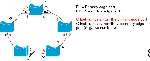
Note ![]() You would never enter an offset value of 1 because that is the offset number of the primary edge port itself.
You would never enter an offset value of 1 because that is the offset number of the primary edge port itself.
If you have configured a preempt delay time by entering the rep preempt delay seconds interface configuration command and a link failure and recovery occurs, VLAN load balancing begins after the configured preemption time period elapses without another link failure. The alternate port specified in the load-balancing configuration blocks the configured VLANs and unblocks all other segment ports. If the primary edge port cannot determine the alternate port for VLAN balancing, the default action is no preemption.
Each port in a segment has a unique port ID. The port ID format is similar to the one used by the spanning tree algorithm: a port number (unique on the bridge) associated to a MAC address (unique in the network). To determine the port ID of a port, enter the show interface interface-id rep detail privileged EXEC command.
Examples
This example shows how to configure REP VLAN load balancing on the Switch B primary edge port (Gigabit Ethernet port 0/1) and to configure Gigabit Ethernet port 0/2 of Switch A as the alternate port to block VLANs 1 to 100. The alternate port is identified by its port ID, shown in bold in the output of the show interface rep detail command for the Switch A port.
Switch A# show interface gigabitethernet0/2 rep detail
GigabitEthernet0/2 REP enabled
Segment-id: 2 (Segment)
PortID: 0080001647FB1780
Preferred flag: No
Operational Link Status: TWO_WAY
Current Key: 007F001647FB17800EEE
Port Role: Open
Blocked Vlan: <empty>
Admin-vlan: 1
Preempt Delay Timer: 35 sec
Load-balancing block port: none
Load-balancing block vlan: none
STCN Propagate to:
PDU/TLV statistics:
LSL PDU rx: 107122, tx: 192493
Switch B# config t
Switch (config)# interface gigabitethernet0/1
Switch (config-if)# rep block port id 0080001647FB1780 vlan 1-100
Switch (config-if)# exit
This example shows how to configure VLAN load balancing by using a neighbor offset number and how to verify the configuration by entering the show interfaces rep detail privileged EXEC command:
Switch# config t
Switch (config)# interface gigabitethernet0/2
Switch (config-if)# rep block port 6 vlan 1-110
Switch (config-if)# end
Switch# show interface gigabitethernet0/2 rep detail
GigabitEthernet0/2 REP enabled
Segment-id: 2 (Segment)
PortID: 0080001647FB1780
Preferred flag: No
Operational Link Status: TWO_WAY
Current Key: 007F001647FB178009C3
Port Role: Open
Blocked Vlan: <empty>
Admin-vlan: 3
Preempt Delay Timer: 35 sec
Load-balancing block port: 6
Load-balancing block vlan: 1-110
STCN Propagate to: none
LSL PDU rx: 1466780, tx: 3056637
HFL PDU rx: 2, tx: 0
BPA TLV rx: 1, tx: 2119695
BPA (STCN, LSL) TLV rx: 0, tx: 0
BPA (STCN, HFL) TLV rx: 0, tx: 0
EPA-ELECTION TLV rx: 757406, tx: 757400
EPA-COMMAND TLV rx: 1, tx: 1
EPA-INFO TLV rx: 178326, tx: 178323
Related Commands
|
|
|
|---|---|
Configures a waiting period after a segment port failure and recovery before REP VLAN load balancing is triggered. |
|
Manually starts REP VLAN load balancing on a segment. |
|
show interfaces rep detail |
Displays REP detailed configuration and status for all interfaces or the specified interface, including the administrative VLAN. |
rep lsl-age-timer
Use the rep lsl-age-timer interface configuration command on a Resilient Ethernet Protocol (REP) port to configure the Link Status Layer (LSL) age timer for the time period that the REP interface remains up without receiving a hello from the REP neighbor. Use the no form of this command to return to the default time.
rep lsl-age timer value
no rep lsl-age timer
Syntax Description
value |
The age-out time in milliseconds. The range is from 120 to 10000 ms in 40-ms increments. The default is 5000 ms (5 seconds). |
Defaults
The REP link shuts down if it does not receive a hello message from a neighbor for 5000 ms.
Command Modes
Interface configuration
Command History
|
|
|
|---|---|
12.2(53)EX |
This command was introduced. |
Usage Guidelines
The LSL hello timer is set to the age-timer value divided by 3 so that there should be at least two LSL hellos sent during the LSL age timer period. If no hellos are received within that time, the REP link shuts down.
In Cisco IOS Release 12.2(52)SE, the LSL age-timer range changed from 3000 to 10000 ms in 500-ms increments to 120 to 10000 ms in 40-ms increments. If the REP neighbor device is not running Cisco IOS Release 12.2(52)SE or later, you must use the shorter time range because the device does not accept values out of the earlier range.
EtherChannel port channel interfaces do not support LSL age-timer values less than 1000 ms. If you try to configure a value less than 1000 ms on a port channel, you receive an error message and the command is rejected.
Examples
This example shows how to configure the REP LSL age timer on a REP link to 7000 ms:
Switch (config)# interface gigabitethernet0/2
Switch (config-if)# rep lsl-age-timer 7000
Switch (config-if)# exit
You can verify the configured ageout time by entering the show interfaces rep detail privileged EXEC command.
Related Commands
|
|
|
|---|---|
show interfaces rep [detail] |
Displays REP configuration and status for all interfaces or the specified interface, including the configured LSL age-out timer value. |
rep preempt delay
Use the rep preempt delay interface configuration command on the REP primary edge port to configure a waiting period after a segment port failure and recovery before Resilient Ethernet Protocol (REP) VLAN load balancing is triggered. Use the no form of this command to remove the configured delay.
rep preempt delay seconds
no rep preempt delay
Syntax Description
seconds |
Set the number of seconds to delay REP preemption. The range is 15 to 300. |
Defaults
No preemption delay is set. If you do not enter the rep preempt delay command, the default is manual preemption with no delay.
Command Modes
Interface configuration
Command History
|
|
|
|---|---|
12.2(53)EX |
This command was introduced. |
Usage Guidelines
You must enter this command on the REP primary edge port.
You must enter this command and configure a preempt time delay if you want VLAN load balancing to automatically trigger after a link failure and recovery.
If VLAN load balancing is configured, after a segment port failure and recovery, the REP primary edge port starts a delay timer before VLAN load balancing occurs. Note that the timer restarts after each link failure. When the timer expires, the REP primary edge alerts the alternate port to perform VLAN load balancing (configured by using the rep block port interface configuration command) and prepares the segment for the new topology. The configured VLAN list is blocked at the alternate port, and all other VLANs are blocked at the primary edge port.
Examples
This example shows how to configure a REP preemption time delay of 100 seconds on the primary edge port:
Switch (config)# interface gigabitethernet0/1
Switch (config-if)# rep preempt delay 100
Switch (config-if)# exit
You can verify your settings by entering the show interfaces rep privileged EXEC command.
Related Commands
|
|
|
|---|---|
Configures VLAN load balancing. |
|
Displays REP configuration and status for all interfaces or a specified interface. |
rep preempt segment
Use the rep preempt segment privileged EXEC command to manually start Resilient Ethernet Protocol (REP) VLAN load balancing on a segment.
rep preempt segment segment_id
Syntax Description
segment-id |
ID of the REP segment. The range is from 1 to 1024. |
Defaults
Manual preemption is the default behavior.
Command Modes
Privileged EXEC
Command History
|
|
|
|---|---|
12.2(53)EX |
This command was introduced. |
Usage Guidelines
When you enter the rep preempt segment segment-id command, a confirmation message appears before the command is executed because preemption can cause network disruption.
Enter this command on the switch on the segment that has the primary edge port.
If you do not configure VLAN load balancing, entering this command results in the default behavior—the primary edge port blocks all VLANs.
You configure VLAN load balancing by entering the rep block port {id port-id | neighbor_offset | preferred} vlan {vlan-list | all} interface configuration command on the REP primary edge port before you manually start preemption.
There is not a no version of this command.
Examples
This example shows how to manually trigger REP preemption on segment 100 with the confirmation message:
Switch)# rep preempt segment 100
The command will cause a momentary traffic disruption.
Do you still want to continue? [confirm]
Related Commands
|
|
|
|---|---|
Configures VLAN load balancing. |
|
show interfaces rep [detail] |
Displays REP configuration and status for all interfaces or the specified interface. |
rep segment
Use the rep segment interface configuration command to enable Resilient Ethernet Protocol (REP) on the interface and to assign a segment ID to it. Use the no form of this command to disable REP on the interface.
rep segment segment-id [edge [no-neighbor] [primary]] [preferred]
no rep segment
Syntax Description
Defaults
REP is disabled on the interface.
When REP is enabled on an interface, the default is for the port to be a regular segment port.
Command Modes
Interface configuration
Command History
|
|
|
|---|---|
12.2(53)EX |
This command was introduced. |
Usage Guidelines
REP ports must be Layer 2 trunk ports.
A non-ES REP port can be either an IEEE 802.1Q trunk port or an ISL trunk port.
REP ports should not be configured as one of these port types:
•![]() SPAN destination port
SPAN destination port
•![]() Private VLAN port
Private VLAN port
•![]() Tunnel port
Tunnel port
•![]() Access port
Access port
•![]() REP ports must be network node interfaces (NNIs). REP ports cannot be user-network interfaces (UNIs) or enhanced network interfaces (ENIs).
REP ports must be network node interfaces (NNIs). REP ports cannot be user-network interfaces (UNIs) or enhanced network interfaces (ENIs).
You must configure two edge ports on each REP segment, a primary edge port and a port to act as a secondary edge port. If you configure two ports in a segment as the primary edge port, for example ports on different switches, the configuration is allowed, but the REP selects one of them to serve as the segment primary edge port.
•![]() REP ports follow these rules:
REP ports follow these rules:
–![]() There is no limit to the number of REP ports on a switch; however, only two ports on a switch can belong to the same REP segment.
There is no limit to the number of REP ports on a switch; however, only two ports on a switch can belong to the same REP segment.
–![]() If only one port on a switch is configured in a segment, the port should be an edge port.
If only one port on a switch is configured in a segment, the port should be an edge port.
–![]() If two ports on a switch belong to the same segment, they must be both edge ports, both regular segment ports, or one regular port and one edge no-neighbor port. An edge port and regular segment port on a switch cannot belong to the same segment.
If two ports on a switch belong to the same segment, they must be both edge ports, both regular segment ports, or one regular port and one edge no-neighbor port. An edge port and regular segment port on a switch cannot belong to the same segment.
–![]() If two ports on a switch belong to the same segment and one is configured as an edge port and one as a regular segment port (a misconfiguration), the edge port is treated as a regular segment port.
If two ports on a switch belong to the same segment and one is configured as an edge port and one as a regular segment port (a misconfiguration), the edge port is treated as a regular segment port.
If you configure two ports in a segment as the primary edge port, for example ports on different switches, the REP selects one of them to serve as the segment primary edge port. Enter the show rep topology privileged EXEC command on a port in the segment to verify which port is the segment primary edge port.
REP interfaces come up in a blocked state and remain in a blocked state until notified that it is safe to unblock. You need to be aware of this to avoid sudden connection losses.
You should configure REP only in networks with redundancy. Configuring REP in a network without redundancy causes loss of connectivity.
In networks where ports on a neighboring switch do not support REP, you can configure the non-REP facing ports as edge no-neighbor ports. These ports inherit all properties of edge ports and you can configure them as any other edge port, including to send STP or REP topology change notices to the aggregation switch. In this case, the STP topology change notice (TCN) that is sent is a multiple spanning-tree (MST) STP message.
Examples
This example shows how to enable REP on a regular (nonedge) segment port:
Switch (config)# interface gigabitethernet0/1
Switch (config-if)# rep segment 100
This example shows how to enable REP on a port and to identify the port as the REP primary edge port:
Switch (config)# interface gigabitethernet0/2
Switch (config-if)# rep segment 100 edge primary
This example shows how to configure the same configuration when the interface has no external REP neighbor:
Switch# configure terminal
Switch (conf)# interface gigabitethernet0/1
Switch (conf-if)# rep segment 100 edge no-neighbor primary
This example shows how to enable REP on a port and to identify the port as the REP secondary edge port:
Switch (config)# interface gigabitethernet0/2
Switch (config-if)# rep segment 100 edge
You can verify your settings by entering the show interfaces rep privileged EXEC command. To verify which port in the segment is the primary edge port, enter the show rep topology privileged EXEC command.
Related Commands
|
|
|
|---|---|
show interfaces rep [detail] |
Displays REP configuration and status for all interfaces or the specified interface. |
show rep topology [detail] |
Displays information about all ports in the segment, including which one was configured and selected as the primary edge port. |
rep stcn
Use the rep stcn interface configuration command on a Resilient Ethernet Protocol (REP) edge port to configure the port to send REP segment topology change notifications (STCNs) to another interface, to other segments, or to Spanning Tree Protocol (STP) networks. Use the no form of this command to disable the sending of STCNs to the interface, segment, or STP network.
rep stcn {interface interface-id | segment id-list | stp}
no rep stcn {interface | segment | stp}
Syntax Description
Defaults
Transmission of STCNs to other interfaces, segments, or STP networks is disabled.
Command Modes
Interface configuration
Command History
|
|
|
|---|---|
12.2(53)EX |
This command was introduced. |
Usage Guidelines
Enter this command on a segment edge port.
You use this command to notify other portions of the Layer 2 network of topology changes that occur in the local REP segment. This removes obsolete entries in the Layer 2 forwarding table in other parts of the network, which allows faster network convergence.
Examples
This example shows how to configure the REP primary edge port to send STCNs to segments 25 to 50:
Switch (config)# interface gigabitethernet0/2
Switch (config-if)# rep stcn segment 25-50
Switch (config-if)# exit
You can verify your settings by entering the show interfaces rep detail privileged EXEC command.
Related Commands
|
|
|
|---|---|
show interfaces rep [detail] |
Displays REP configuration and status for all interfaces or the specified interface. |
reserved-only
Use the reserved-only DHCP pool configuration mode command to allocate only reserved addresses in the Dynamic Host Configuration Protocol (DHCP) address pool. Use the no form of the command to return to the default.
reserved-only
no reserved-only
Syntax Description
This command has no arguments or keywords.
Defaults
The default is to not restrict pool addresses
Command Modes
Privileged EXEC
Command History
|
|
|
|---|---|
12.2(53)EX |
This command was introduced. |
Usage Guidelines
Entering the reserved-only command restricts assignments from the DHCP pool to preconfigured reservations. Unreserved addresses that are part of the network or on pool ranges are not offered to the client, and other clients are not served by the pool.
By entering this command, users can configure a group of switches with DHCP pools that share a common IP subnet and that ignore requests from clients of other switches.
To access DHCP pool configuration mode, enter the ip dhcp pool name global configuration command.
Examples
This example shows how to configure the DHCP pool to allocate only reserved addresses:
Switch# config t
Enter configuration commands, one per line. End with CNTL/Z.
Switch(config)# ip dhcp pool test1
Switch(dhcp-config)# reserved-only
You can verify your settings by entering the show ip dhcp pool privileged EXEC command.
Related Commands
|
|
|
|---|---|
show ip dhcp pool |
Displays the DHCP address pools. |
 Feedback