- Preface
- Product Overview
- Using the Command Line
- Configuring the Interfaces
- IP Mobility
- Introduction to Radio Aware Routing and MANET
- Understanding and Configuring DLEP
- Configuring R2CP
- Configuring PPPoE
- OSPFv3 Address Families
- Configuring OSPFv3 for a MANET
- Configuring EIGRP in a MANET
- Understanding and Configuring IP Multiplexing
- Zeroization
- Command Reference
- System Message Overview
- Technical Support Reference
- Understanding The Enhanced Interior Gateway Protocol
- Using EIGRP Cost Metrics for VMI Interfaces
- Understanding VMI Metric to EIGRP Metric Conversion
- Understanding EIGRP Metric Dampening for VMI
- Understanding Neighbor Up/Down Signaling for EIGRP
- Enabling EIGRP for IPv4
- Activating EIGRP IPv4 on a Configured VMI
- Enabling EIGRP for IPv6
- Setting the EIGRP Metric Change-based Dampening for VMI
- Setting the EIGRP Interval-based Metric Dampening for VMI
Configuring EIGRP in a MANET
This chapter explains how to configure the Enhanced Interior Gateway Routing Protocol (EIGRP) in a MANET.
This chapter includes the following major sections:
- Understanding The Enhanced Interior Gateway Protocol
- Using EIGRP Cost Metrics for VMI Interfaces
- Understanding VMI Metric to EIGRP Metric Conversion
- Understanding EIGRP Metric Dampening for VMI
- Understanding Neighbor Up/Down Signaling for EIGRP
- Enabling EIGRP for IPv4
- Activating EIGRP IPv4 on a Configured VMI
- Enabling EIGRP for IPv6
- Setting the EIGRP Metric Change-based Dampening for VMI
- Setting the EIGRP Interval-based Metric Dampening for VMI
Understanding The Enhanced Interior Gateway Protocol
The Enhanced Interior Gateway Routing Protocol (EIGRP) integrates the capabilities of link-state protocols into distance vector protocols. EIGRP is distinguished from other routing protocols by the following key capabilities:
- Fast convergence
- Supports variable-length subnet mask
- Supports partial updates
- Supports multiple network layer protocols
A router running EIGRP stores all of its neighbors' routing tables so that the router running EIGRP can quickly adapt to alternate routes. If no appropriate route exists, EIGRP queries its neighbors to discover an alternate route. These queries propagate until an alternate route is found.
EIGRP supports variable-length subnet masks permitting routes to be automatically summarized on a network number boundary. EIGRP can be configured to summarize on any bit boundary at any interface.
EIGRP does not make periodic updates. EIGRP sends partial updates when the route metric changes. Propagation of partial updates is automatically bounded, so only routers needing the information update. EIGRP consumes significantly less bandwidth than the Interior Gateway Routing Protocol (IGRP).
Using EIGRP Cost Metrics for VMI Interfaces
When using EIGRP as the routing protocol, metrics allow EIGRP to respond to routing changes. The link-state metric is advertised as the link cost in the router link advertisement. The reply sent to any routing query always contains the latest metric information. The following exceptions result in an immediate update being sent:
- A down interface
- A down route
- Any change in metrics that result in the router selecting a new next hop
EIGRP receives dynamic raw radio link characteristics and computes a composite EIGRP metric based on a proprietary formula. To avoid churn in the network as a result of the change in the link characteristics, EIGRP uses a tunable dampening mechanism.
EIGRP uses the metric weights along with a set of vector metrics to compute the composite metric for local Routing Information Base (RIB) installation and route selections. The EIGRP composite metric is calculated using the formula:
metric = [K1 * BW + (K2 * BW) / (256 - Load) + K3 * Delay] * [K5 / (Reliability + K4)]

Note![]() Use K values only after careful planning. Mismatched K values prevent a neighbor relationship from being built, which can cause your network to fail to converge.
Use K values only after careful planning. Mismatched K values prevent a neighbor relationship from being built, which can cause your network to fail to converge.
Note![]() If K5 = 0, the formula reduces to metric = [K1 * BW + (K2 * BW)/(256 - Load) + K3 * Delay].
If K5 = 0, the formula reduces to metric = [K1 * BW + (K2 * BW)/(256 - Load) + K3 * Delay].
Table 11-1 lists the EIGRP vector metrics and their descriptions.
EIGRP monitors metric weights on an interface to allow for the tuning of EIGRP metric calculations and indicate Type of Service (ToS). Table 11-2 lists the K-values and their default.
|
|
|
|---|---|
As shown in Table 11-2 , cost configurations use the first two metrics—delay and bandwidth. The default formula of (BW +Delay) is the EIGRP metric. The bandwidth for the formula is scaled and inverted by the following formula:
(10^7/minimum BW in kilobits per second)
Note![]() You can change the weights, but these weights must be the same on all the routers.
You can change the weights, but these weights must be the same on all the routers.
For example, look at an EIGRP link where the bandwidth to a particular destination is 128k and the Relative Link Quality (RLQ) is 50 percent.
BW = (256 * 10000000) / 128 = 20000000
Delay = (((10000000000 / 128) * 100) / (50 * 1000)) * 256 = (40000000 / 10) = 4000000
Using the cut-down formula, the EIGRP metric calculation would simplify to 256*(BW + Delay), resulting in the following value:
Understanding VMI Metric to EIGRP Metric Conversion
With the VMI interface, the quality of connection to a neighbor varies based on a number of characteristics computed dynamically as a result of layer 2 feedback to layer 3. Table 11-3 lists the metrics and their significance.
Table 11-4 lists these EIGRP vector metric values map to the basic EIGRP interface parameters.
Note![]() Although not explicit in Table 11-4, all variables are converted to the proper units.
Although not explicit in Table 11-4, all variables are converted to the proper units.
|
|
|
|
|---|---|---|
| delay = 256 * (1E10 / (current data rate / 1000)) * ((100 / relative link quality) / 1000) / 10 |
||
Understanding EIGRP Metric Dampening for VMI
Because metric components can change rapidly, the frequency of the changes have an impact on the network. Frequent changes require that prefixes learned though the VMI be updated and sent to all adjacencies. This update can result in further updates and, in a worst-case scenario, cause network-wide churn. To prevent such effects, metrics can be dampened, or thresholds set, so that any change that does not exceed the dampening threshold is ignored.
The following network changes cause an immediate update:
- A down interface
- A down route
- Any change in a metric that results in the router selecting a new next hop
Dampening the metric changes can be configured based on change or time intervals.
If the dampening method is change-based, changes in routes learned though a specific interface, or in the metrics for a specific interface, are not advertised to adjacencies until the computed metric changes from the last advertised value significantly enough to cause an update to be sent.
If the dampening method is interval-based, changes in routes learned though a specific interface, or in the metrics for a specific interface, are not advertised to adjacencies until the specified interval is met, unless the change results in a new route path selection.
When the timer expires, any routes with outstanding changes to report are sent out. If a route changes, such that the final metric of the route matches the last updated metric, no update is sent.
Understanding Neighbor Up/Down Signaling for EIGRP
MANETs are highly dynamic environments. Nodes may move in to, or out of, radio range at a fast pace. Each time a node joins or leaves, the network topology must be logically reconstructed by the routers. Routing protocols normally use timer-driven “hello” messages or neighbor time-outs to track topology changes. MANETs reliance on these mechanisms can result in unacceptably slow convergence.
This signaling capability provides faster network convergence by using link-status signals generated by the radio. The radio notifies the router each time a link to another neighbor is established or terminated by the creation and termination of PPPoE sessions. In the router, the EIGRP responds immediately to these signals by expediting the formation of a new adjacency (for a new neighbor) or tearing down an existing adjacency (if a neighbor is lost). For example, if a vehicle drives behind a building and loses its connection, the router immediately senses the loss and establishes a new route to the vehicle through neighbors that are not blocked. This high speed network convergence is essential for minimizing dropped voice calls and disruptions to video sessions.
When VMI with PPPoE is used and a partner node has left or a new one has joined, the radio informs the router immediately of the topology change. Upon receiving the signal, the router immediately declares the change and updates the routing tables.
The signaling capability offers the following benefits:
- Reduces routing delays and prevents applications from timing out
- Enables network-based applications and information to be delivered reliably and quickly over directional radio links
- Provides faster convergence and optimal route selection so that delay-sensitive traffic such as voice and video are not disrupted
- Reduces impact on radio equipment by minimizing the need for internal queuing/buffering
- Provides consistent Quality of Service (QoS) for networks with multiple radios
The messaging allows for flexible rerouting when necessary because of the following factors:
- Noise on the Radio links
- Fading of the Radio links
- Congestion of the Radio links
- Radio link power fade
- Utilization of the Radio
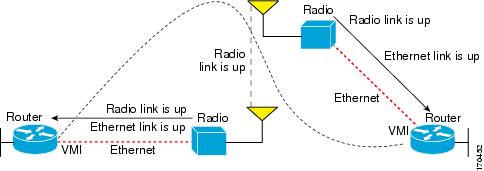
Figure 11-1 illustrates the signaling sequence that occurs when radio links go up and down.
Figure 11-1 Up and Down Signaling Sequence
Enabling EIGRP for IPv4
To create an EIGRP routing process, use the following commands beginning in global configuration mode:
SUMMARY STEPS
DETAILED STEPS
Activating EIGRP IPv4 on a Configured VMI
Perform this task to activate EIGRP IPv4 on a configured VMI.
SUMMARY STEPS
3.![]() interface vmi interface-number
interface vmi interface-number
5.![]() no ip split-horizon eigrp as-number
no ip split-horizon eigrp as-number
DETAILED STEPS
Enabling EIGRP for IPv6
Perform the following task to enable EIGRP for IPv6 on a specified interface. EIGRP for IPv6 is directly configured on the interfaces over which it runs, which allows EIGRP for IPv6 to be configured without the use of a global IPv6 address.
SUMMARY STEPS
8.![]() ipv6 router eigrp as-number
ipv6 router eigrp as-number
DETAILED STEPS
Setting the EIGRP Metric Change-based Dampening for VMI
Perform the following tasks to set the change-based dampening interval for VMI:
This configuration assumes that a virtual template and appropriate PPPoE configurations have already been completed. Refer to the Cisco IOS IP Mobility Configuration Guide for VMI configuration details.
This configuration sets the threshold to 50 percent tolerance routing updates involving VMIs and peers.
SUMMARY STEPS
4.![]() eigrp as-number interface [ dampening-change value ] [ dampening-interval value ]
eigrp as-number interface [ dampening-change value ] [ dampening-interval value ]
DETAILED STEPS
Setting the EIGRP Interval-based Metric Dampening for VMI
Perform this task to set an interval-based dampening interval for VMI interfaces.
This configuration assumes that a virtual template and appropriate PPPoE configurations have already been completed. Refer to the Cisco IOS IP Mobility Configuration Guide for VMI configuration details.
This configuration sets the interval to 30 seconds at which updates occur for topology changes that affect VMI interfaces and peers:
SUMMARY STEPS
4.![]() eigrp as-number interface [ dampening-change value ] [ dampening-interval value ]
eigrp as-number interface [ dampening-change value ] [ dampening-interval value ]
DETAILED STEPS
|
|
|
|
|---|---|---|
|
|
||
|
|
||
interface vmi 1
|
||
|
|
||
|
|
Examples
Basic VMI PPPoE Configuration with EIGRP IPv4
The following example illustrates the simplest configuration using EIGRP as the routing protocol. This configuration includes one VMI.
Basic VMI PPPoE Configuration Using EIGRP for IPv6
This example shows the basic requirements for configuring a VMI that uses EIGRP for IPv6 as the routing protocol. It includes one VMI.
VMI PPPoE Configuration Using EIGRP for IPv4 and IPv6
The following examples shows the configuration VMI PPPoE using EIGRP as the IP routing protocol when you have both IPv4 and IPv6 addresses configured on the interface. This configuration includes one VMI. While EIGRP allows you to use the same AS number on an IPv4 EIGRP process and on an IPv6 process, we recommend using a unique AS number for each process for clarity.
EIGRP Metric Dampening for VMI Interfaces
The eigrp interface command advertises routing changes for EIGRP traffic only.
The REPLY sent to any QUERY will always contain the latest metric information. The following exceptions result in an immediate UPDATE:
- A down interface
- A down route
- Any change in metric which results in the router selecting a new next hop
To prevent network-wide churn from frequent metric changes from impacting the network, even causing network-wide churn, metrics can be dampened, or thresholds set, so that any change that does not exceed the dampening threshold is ignored. The examples in this section show how to set the EIGRP dampening intervals to avoid such impacts.
EIGRP Change-based Metric Dampening for VMI Interfaces
The following example sets the threshold to 50 percent tolerance routing updates involving VMIs and peers:
EIGRP Interval-based Metric Dampening for VMI Interfaces
The following example sets the interval to 30 seconds at which updates occur for topology changes that affect VMIs and peers:
The following examples show the configuration of VMI bypass mode with EIGRP IPv4, EIGRP IPv6, and EIGRP for IPv4 and IPv6.
VMI Bypass mode PPPoE Configuration Using EIGRP for IPv6:
VMI Bypass mode PPPoE Configuration with EIGRP IPv4:
VMI Bypass mode PPPoE Configuration Using EIGRP for IPv4 and IPv6:
 Feedback