Virtualized Multiservice Data Center (VMDC) Virtualized Services Architecture (VSA) 1.0, Design Guide
Bias-Free Language
The documentation set for this product strives to use bias-free language. For the purposes of this documentation set, bias-free is defined as language that does not imply discrimination based on age, disability, gender, racial identity, ethnic identity, sexual orientation, socioeconomic status, and intersectionality. Exceptions may be present in the documentation due to language that is hardcoded in the user interfaces of the product software, language used based on RFP documentation, or language that is used by a referenced third-party product. Learn more about how Cisco is using Inclusive Language.
- Updated:
- May 12, 2014
Chapter: Preface
Preface
The Cisco Virtualized Multiservice Data Center (VMDC) system provides design and implementation guidance for enterprises deploying private cloud services, and for service providers (SPs) building public and virtual private services. With the goal of providing an end-to-end system architecture, VMDC integrates Cisco and third-party products in the cloud computing ecosystem.
Audience
This guide is intended for, but not limited to, system architects, network design engineers, system engineers, field consultants, advanced services specialists, and customers who want to understand how to deploy a public or private cloud data center infrastructure. This guide assumes that the reader is familiar with the basic concepts of IP protocols, quality of service (QoS), and high availability (HA), and that readers are aware of general system requirements and have a basic understanding of enterprise or SP network and data center architectures.
Overview
VMDC, Cisco’s reference architecture for cloud deployment, has been widely adopted by numerous SPs and enterprises worldwide. In this and previous releases, VMDC has provided design guidance for scalable, secure, resilient, public and private cloud infrastructures serving multiple consumers or tenants:
- In the data center portion of the architecture, VMDC 2.X designs were centered on traditional hierarchical infrastructure models incorporating leading Cisco platforms and Layer 2 (L2) resilience technologies such as Virtual Port Channel (vPC), providing network containers or tenancy models of different sizes and service profiles, with necessary network based services and orchestration and automation capabilities to accommodate the various needs of cloud providers and consumers.
- VMDC 3.X systems releases introduced Cisco FabricPath for intra-DC networks, as an optional L2 alternative to a hierarchical vPC-based design. FabricPath removes the complexities of Spanning Tree Protocol (STP) to enable more extensive, flexible, and scalable L2 designs. Customers leveraging VMDC reference architecture models can choose between vPC-based and FabricPath-based designs to meet their particular requirements.
VMDC VSA 1.0 is the first VMDC release dealing specifically with the transition to NFV (Network Function Virtualization) of IaaS network services in the data center. Such services comprise virtual routers, virtual firewalls, load balancers, network analysis and WAN optimization virtual appliances.
In this release, we focus mainly on public provider use cases, building a new logical topology model around the creation of virtual private cloud tenant containers in the shared data center infrastructure. Future releases will incorporate additional cloud consumer models specific to enterprise and private cloud use cases. In particular, future releases will address hybrid consumer models, comprising physical and virtual service appliances, used together as part of a per-consumer or per-tenant service set. These can be implemented on either a 2.X (classical Ethernet) or 3.X (FabricPath) VMDC infrastructure. However, in this release we focus on fundamental implications of an all-virtual approach, and have opted to do so over a simple FabricPath data center topology previously validated in VMDC 3.0.
Problem Statement
The architecture described in this guide addresses the following customer challenges:
1.![]() Tenancy Scale—Previous VMDC systems releases leveraged various abstraction technologies, for example, virtual LANs (VLANs) and virtual routing and forwarding (VRF), for tenant isolation, including separated routing and forwarding. Each abstraction technology impacts logical scale and control plane overhead. In a traditional hierarchical DC network model, the pressure point from a scalability and control plane perspective is at the aggregation layer of the infrastructure, with the number of route peers, VRFs, VLANs, and MAC capacity supported by aggregation nodes presenting key multi-dimensional scalability factors. The virtual services architectural (VSA) model introduced in this release presents an alternative, addressing tenancy scale using a centralized provider edge (PE) and distributed, per-tenant virtual customer edge (vCE) routing model. Tenancy scale is thus increased to the number of eBGP peers (or alternatively, static routes) supported by the PE nodes. As of this writing, this is 5000 per pair of redundant ASR 9000 Series PE routers.
Tenancy Scale—Previous VMDC systems releases leveraged various abstraction technologies, for example, virtual LANs (VLANs) and virtual routing and forwarding (VRF), for tenant isolation, including separated routing and forwarding. Each abstraction technology impacts logical scale and control plane overhead. In a traditional hierarchical DC network model, the pressure point from a scalability and control plane perspective is at the aggregation layer of the infrastructure, with the number of route peers, VRFs, VLANs, and MAC capacity supported by aggregation nodes presenting key multi-dimensional scalability factors. The virtual services architectural (VSA) model introduced in this release presents an alternative, addressing tenancy scale using a centralized provider edge (PE) and distributed, per-tenant virtual customer edge (vCE) routing model. Tenancy scale is thus increased to the number of eBGP peers (or alternatively, static routes) supported by the PE nodes. As of this writing, this is 5000 per pair of redundant ASR 9000 Series PE routers.
2.![]() Complexity—Current VMDC architecture models feature a relatively high degree of management complexity because service appliances are shared across multiple tenants, and are allocated in logical “slices” (contexts) by automation systems. The VSA model reduces service orchestration complexity, removing cross-tenant dependencies for L4-L7 service allocation. The VSA model represents a simpler logical topology compared to the back-to-back VRF-Lite method employed in VMDC 2.X releases to create rigorous (VRF-based) tenant isolation.
Complexity—Current VMDC architecture models feature a relatively high degree of management complexity because service appliances are shared across multiple tenants, and are allocated in logical “slices” (contexts) by automation systems. The VSA model reduces service orchestration complexity, removing cross-tenant dependencies for L4-L7 service allocation. The VSA model represents a simpler logical topology compared to the back-to-back VRF-Lite method employed in VMDC 2.X releases to create rigorous (VRF-based) tenant isolation.
3.![]() Customer Evolution to NFV for IaaS—For years, customers have seen the transition from physical to virtual services as a foundation for an evolution toward “next-gen” data center service-oriented architectures, providing increased flexibility and agility through greater “software definition”.
Customer Evolution to NFV for IaaS—For years, customers have seen the transition from physical to virtual services as a foundation for an evolution toward “next-gen” data center service-oriented architectures, providing increased flexibility and agility through greater “software definition”.
4.![]() Need for Virtual Appliance-Based Multi-Tenancy Design Guidance—VMDC VSA 1.0 is a starting point, representing an opportunity to initially consider one specific deployment model (the vCE model) out of several possible options for an “all-virtual” virtual private cloud instantiation, exploring end-to-end service differentiation, performance and impact on future automation requirements.
Need for Virtual Appliance-Based Multi-Tenancy Design Guidance—VMDC VSA 1.0 is a starting point, representing an opportunity to initially consider one specific deployment model (the vCE model) out of several possible options for an “all-virtual” virtual private cloud instantiation, exploring end-to-end service differentiation, performance and impact on future automation requirements.
5.![]() Need to Address Logical Segmentation Constraints—of traditional 802.1q VLAN L2 domains through the application of virtual overlays. VMDC VSA 1.0 presents a first look at the use of VXLANs for logical segmentation.
Need to Address Logical Segmentation Constraints—of traditional 802.1q VLAN L2 domains through the application of virtual overlays. VMDC VSA 1.0 presents a first look at the use of VXLANs for logical segmentation.
Solution Proposal
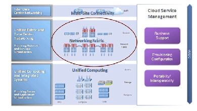
To address the identified requirements, we modified the Unified Computing component of the VMDC architecture, shifting virtualized service functions from the Unified Fabric/Data Center Networking portions of the infrastructure. Figure ii-1 shows a high level view of the overall VMDC system.
In general, the solution comprises three modular layers:
1.![]() Unified Computing and Integrated Systems (UCIS), providing server and application virtualization, typically consisting of FlexPods and Vblocks.
Unified Computing and Integrated Systems (UCIS), providing server and application virtualization, typically consisting of FlexPods and Vblocks.
2.![]() Unified Fabric and Data Center Networking (UFDC), providing network and network based services virtualization.
Unified Fabric and Data Center Networking (UFDC), providing network and network based services virtualization.
3.![]() Data Center Interconnect (DCI), providing seamless multi-site connectivity.
Data Center Interconnect (DCI), providing seamless multi-site connectivity.
The solution is complemented by Cloud Service Management components that enable end to end provisioning and orchestration, along with monitoring and assurance.
Figure ii-1 High Level VMDC Solution
VMDC VSA 1.0 shifts network service functions to the UCIS in a way that leverages existing design guidance for the Unified Fabric and DCI layers, along with previous guidance for the UCIS layers in terms of compute and storage for application workloads. We maintained the following assumptions:
- Previous design guidance for UCIS (FlexPod, Vblock) components applies. VMDC VSA 1.0 validation was performed on the latest FlexPod release. Applications validated on FlexPod or Vblock continue to function on the overall VMDC architecture.
- Previous design guidance for DCI components applies. VMDC VSA 1.0 focuses mainly on single-site, intra-PoD Virtual Private Cloud (VPC) design alternatives.
- There are no top-level management and orchestration components in VMDC VSA 1.0: orchestration and service assurance are addressed in separate, parallel VMDC programs.
- Cisco (XaaS) applications, such as Unified Communications (UC), Hosted Collaboration Solution (HCS), Media Data Center, Video Surveillance, and TelePresence, use the VMDC architecture as the infrastructure for validation. At this writing, VMDC 2.3 is the latest release used for these validations. No specific Cisco application validations are in the scope of VMDC VSA 1.0. However, given the level of validation already performed, we are confident that these applications will work in VMDC VSA 1.0 infrastructures without major issues.
 Feedback