Cisco Virtualized Workload Mobility Design Considerations
The overall end-to-end architecture leveraged for the validation of the virtualized workload mobility solution is shown in Figure 2-1.
Figure 2-1 End-to-End Architecture
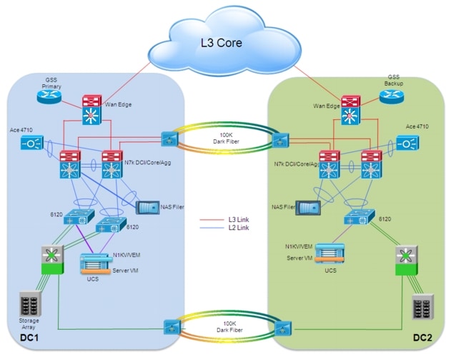
As shown, the data center design leverages the usual separation in tiers:
•![]() Starting from the edge, a Cisco Unified Computing System (UCS) chassis is connected to a redundant pair of 6120 Fabric Interconnect devices. Each blade inserted in the UCS chassis represents a separate ESX host, used to deploy multiple Virtual Machines. Cisco Nexus 1000V is the distributed Virtual Switch (dVS) validated for this specific deployment. The Virtual Ethernet Modules (VEMs) representing the "linecards" of the distributed Virtual Switch are "stretched" across the two data center locations depicted above.
Starting from the edge, a Cisco Unified Computing System (UCS) chassis is connected to a redundant pair of 6120 Fabric Interconnect devices. Each blade inserted in the UCS chassis represents a separate ESX host, used to deploy multiple Virtual Machines. Cisco Nexus 1000V is the distributed Virtual Switch (dVS) validated for this specific deployment. The Virtual Ethernet Modules (VEMs) representing the "linecards" of the distributed Virtual Switch are "stretched" across the two data center locations depicted above.
•![]() Each 6120 Fabric Interconnect device is connected with a port-channel to a pair of Nexus 7000 devices, representing a collapsed DC Core and aggregation layer. The Fabric Interconnect devices establish also Fibre Channel connections to the Storage Area Network (SAN) represented by a Cisco MDS 9509 director class switch.
Each 6120 Fabric Interconnect device is connected with a port-channel to a pair of Nexus 7000 devices, representing a collapsed DC Core and aggregation layer. The Fabric Interconnect devices establish also Fibre Channel connections to the Storage Area Network (SAN) represented by a Cisco MDS 9509 director class switch.
•![]() Network services, like the NAS device or the Cisco Application Control Engine (ACE) are directly connected to the aggregation layer switches leveraging logical port-channels.
Network services, like the NAS device or the Cisco Application Control Engine (ACE) are directly connected to the aggregation layer switches leveraging logical port-channels.
•![]() The aggregation devices are then connected to the DC WAN Edge, to provide access to the L3 Core of the network (it could be a MAN/WAN enterprise core or a SP offered service). The L3 core of the network is where are originated the clients connections accessing specific data center services and applications. The Cisco Global Site Selector (GSS) devices are directly connected to the WAN Edge devices.
The aggregation devices are then connected to the DC WAN Edge, to provide access to the L3 Core of the network (it could be a MAN/WAN enterprise core or a SP offered service). The L3 core of the network is where are originated the clients connections accessing specific data center services and applications. The Cisco Global Site Selector (GSS) devices are directly connected to the WAN Edge devices.
 |
Note |
Some general considerations in the context of the virtualized workload mobility solution validated and documented in this paper are as follows:
•![]() The two data center sites are 100 kilometers apart and connected via point-to-point protected DWDM circuits. This represents the typical scenario of "Twins DC sites", usually deployed in a Metro area. The desire is usually to consider and operate the twin sites as a single virtual data center. Dedicated DWDM connections are also leveraged to extend Fibre Channel connectivity between sites (when needed) or to perform data synchronization/replication.
The two data center sites are 100 kilometers apart and connected via point-to-point protected DWDM circuits. This represents the typical scenario of "Twins DC sites", usually deployed in a Metro area. The desire is usually to consider and operate the twin sites as a single virtual data center. Dedicated DWDM connections are also leveraged to extend Fibre Channel connectivity between sites (when needed) or to perform data synchronization/replication.
•![]() As previously discussed, a holistic Data Center Interconnect solution presents various functional components. Various technologies have been considered as part of this effort for covering these DCI functional blocks. More specifically:
As previously discussed, a holistic Data Center Interconnect solution presents various functional components. Various technologies have been considered as part of this effort for covering these DCI functional blocks. More specifically:
–![]() LAN Extension: given the availability of point-to-point circuits between the two sites, two different flavors of LAN extension technologies have been configured. The first one leverages the virtual PortChannel (vPC) capabilities of Nexus 7000 devices to establish an end-to-end port-channel between the Nexus 7000 pairs deployed in each data center. The second introduces Overlay Transport Virtualization (OTV), Cisco innovative LAN extension technology, deployed in this case across dark fiber connections between sites.
LAN Extension: given the availability of point-to-point circuits between the two sites, two different flavors of LAN extension technologies have been configured. The first one leverages the virtual PortChannel (vPC) capabilities of Nexus 7000 devices to establish an end-to-end port-channel between the Nexus 7000 pairs deployed in each data center. The second introduces Overlay Transport Virtualization (OTV), Cisco innovative LAN extension technology, deployed in this case across dark fiber connections between sites.
–![]() Routing: the DCI connection between sites is used both for sending LAN extension traffic and for routed communications between subnets that are not stretched. As discussed in the "LAN extension" section, satisfying this requirement has design implications dependent on the specific LAN extension technology deployed.
Routing: the DCI connection between sites is used both for sending LAN extension traffic and for routed communications between subnets that are not stretched. As discussed in the "LAN extension" section, satisfying this requirement has design implications dependent on the specific LAN extension technology deployed.
–![]() Path Optimization: the basic assumption for this design is that clients access applications by connecting to the VIP address of a load balancer. This allows implementing a DNS based method to redirect traffic to the data center where a specific application is available. The DNS based approach validated and documented in this document leverages the integration between Cisco Application Control Engine (ACE), Cisco Global Site Selector (GSS) and VMware vCenter server.
Path Optimization: the basic assumption for this design is that clients access applications by connecting to the VIP address of a load balancer. This allows implementing a DNS based method to redirect traffic to the data center where a specific application is available. The DNS based approach validated and documented in this document leverages the integration between Cisco Application Control Engine (ACE), Cisco Global Site Selector (GSS) and VMware vCenter server.
–![]() Workload Mobility: virtualized workload mobility is the core functionality discussed in this document. Live mobility leveraging VMware vMotion is the solution validated in this context. Cisco specific technologies, like the Nexus 1000V distributed switch and the Virtual Services Gateway (VSG) are also integrated to enrich the capabilities offered by the workload mobility solution.
Workload Mobility: virtualized workload mobility is the core functionality discussed in this document. Live mobility leveraging VMware vMotion is the solution validated in this context. Cisco specific technologies, like the Nexus 1000V distributed switch and the Virtual Services Gateway (VSG) are also integrated to enrich the capabilities offered by the workload mobility solution.
–![]() Storage Elasticity: moving workloads between sites brings challenges in terms of how these workloads maintain access to the storage disk (physical or virtual). The goal from this point of view is to discuss and compare different deployment model, starting with the shared storage one and moving then toward more advanced intelligent storage approaches like active/cache and active/active.
Storage Elasticity: moving workloads between sites brings challenges in terms of how these workloads maintain access to the storage disk (physical or virtual). The goal from this point of view is to discuss and compare different deployment model, starting with the shared storage one and moving then toward more advanced intelligent storage approaches like active/cache and active/active.
The following sections of this chapter discuss in greater detail design considerations around the deployment of each DCI functional component listed above.
LAN Extension
LAN extension solutions are commonly used to extend subnets beyond the traditional Layer 3 boundaries of a single data center. Stretching the network space across two or more data centers can accomplish many things. Doing so also presents a challenge, since providing these LAN extension capabilities may have an impact on the overall network design. Simply allowing Layer 2 connectivity between sites that were originally connected only at Layer 3 would have the consequence of creating new traffic patterns between the sites: STP BPDUs, unicast floods, broadcasts, ARP requests, and so on. This can create issues, some of them related to attacks (ARP or flood storms), others related to stability issues (size of STP domain) or scale (ARP caches or MAC address table sizes). How does an extended spanning-tree environment avoid loops and broadcast storms? How does a core router know where an active IP address or subnet exists at any given time?
LAN Extension Technical Requirements
For deploying a LAN extension solution, it is important to consider the following two key requirements:
•![]() Spanning-Tree (STP) Isolation: the first basic requirement is to isolate the Spanning Tree domains between the data center sites belonging to the extended Layer 2 network. This is important to protect against any type of global disruptions that could be generated by a remote failure, and to mitigate the risk of propagating unwanted behavior such as topology change or root bridge movement from one data center to another. These packets could be flooded throughout the Layer 2 network, making all remote data centers and resources unstable, or even inaccessible.
Spanning-Tree (STP) Isolation: the first basic requirement is to isolate the Spanning Tree domains between the data center sites belonging to the extended Layer 2 network. This is important to protect against any type of global disruptions that could be generated by a remote failure, and to mitigate the risk of propagating unwanted behavior such as topology change or root bridge movement from one data center to another. These packets could be flooded throughout the Layer 2 network, making all remote data centers and resources unstable, or even inaccessible.
•![]() End-to-End loop prevention: In each data center site, the deployment of redundant physical devices providing LAN extension services is recommended to improve the overall resiliency of the LAN Extension solution. Therefore, a solution must eliminate any risk of creating an end-to-end Layer 2 loop; STP cannot be used for this purpose, given the previous requirement of isolating the STP domains between remote DC sites.
End-to-End loop prevention: In each data center site, the deployment of redundant physical devices providing LAN extension services is recommended to improve the overall resiliency of the LAN Extension solution. Therefore, a solution must eliminate any risk of creating an end-to-end Layer 2 loop; STP cannot be used for this purpose, given the previous requirement of isolating the STP domains between remote DC sites.
In addition to these, other requirements to consider are:
•![]() WAN Load Balancing: Typically, WAN links are expensive, so the uplinks need to be fully utilized, with traffic load-balanced across all available uplinks.
WAN Load Balancing: Typically, WAN links are expensive, so the uplinks need to be fully utilized, with traffic load-balanced across all available uplinks.
•![]() Core Transparency: The LAN extension solution should ideally be transparent to the existing enterprise core, to minimize the operational impact.
Core Transparency: The LAN extension solution should ideally be transparent to the existing enterprise core, to minimize the operational impact.
•![]() Data Center Site Transparency: The LAN extension solution should not affect the existing data center network deployment.
Data Center Site Transparency: The LAN extension solution should not affect the existing data center network deployment.
•![]() VLAN Scalability: The solution should be able to scale to extend up to hundreds (sometimes few thousands) of VLANs.
VLAN Scalability: The solution should be able to scale to extend up to hundreds (sometimes few thousands) of VLANs.
•![]() Multisite Scalability: The LAN extension solution should be able to scale to connect multiple data centers.
Multisite Scalability: The LAN extension solution should be able to scale to connect multiple data centers.
•![]() Hierarchical Quality of Service (HQoS): HQoS is typically needed at the WAN edge to shape traffic when an enterprise subscribes to a sub-rate service provider service or a multipoint Ethernet virtual private line (EVPL) service.
Hierarchical Quality of Service (HQoS): HQoS is typically needed at the WAN edge to shape traffic when an enterprise subscribes to a sub-rate service provider service or a multipoint Ethernet virtual private line (EVPL) service.
•![]() Encryption: The requirement for LAN extension cryptography is increasingly prevalent, to meet federal and regulatory requirements.
Encryption: The requirement for LAN extension cryptography is increasingly prevalent, to meet federal and regulatory requirements.
The following two sections introduce the two Cisco LAN Extension solutions that were included as part of the virtualized workload mobility architecture validation.
vPC over Dark Fiber
The virtual Port Channel (vPC) functionality allows establishing port channel distributed across two devices, allowing redundant yet loop-free topology. Compared to traditional STP-based environments, vPC allows redundant paths between a downstream device and its two upstream neighbors. With STP, the port channel is a single logical link that allows for building Layer 2 topologies that offer redundant paths without STP blocking redundant links.
Figure 2-2 STP and vPC Topologies
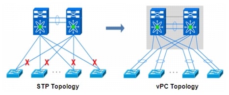
Despite the fact that the vPC technology has been originally designed to be used intra-DC, the capabilities of bundling links belonging to separate devices into a single logical port-channel can provide a good solution to extend VLAN connectivity between data center sites interconnected with dark fiber (or protected DWDM) connections, as shown in Figure 2-3.
Figure 2-3 vPC Deployment over Dark Fiber
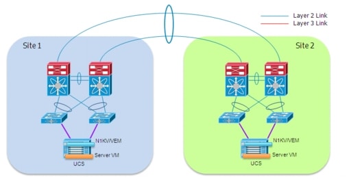
The main advantage of bundling together the physical point-to-point links interconnecting the sites consist in being capable of extending VLANs without creating L2 looped topologies. As a consequence, the recommendation is to filter Spanning Tree BPDUs across the logical port-channel established between sites, so to be able to isolate the STP domains (which represent one of the main technical requirements of any LAN extension solution). Essentially, the idea is to replace STP with LACP as control plane protocol.
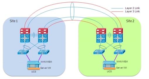
One of the shortcomings of this solution is the lack of capability of providing L2 and L3 communication across the same bundled links. This is because of the current lack of support for dynamic IGP peering establishment across a vPC connection. The recommended workaround implemented as part of this validation effort is leveraging a pair of extra L3 links to be specifically used for routed communication, as shown in Figure 2-4.
Figure 2-4 Addition of Dedicated L3 Links
 |
Note |
OTV over Dark Fiber
Overlay Transport Virtualization (OTV) is an IP-based functionality that has been designed from the ground up to provide Layer 2 extension capabilities over any transport infrastructure: Layer 2 based, Layer 3 based, IP switched, label switched, and so on. The only requirement from the transport infrastructure is providing IP connectivity between remote data center sites. In addition, OTV provides an overlay that enables Layer 2 connectivity between separate Layer 2 domains while keeping these domains independent and preserving the fault-isolation, resiliency, and load balancing benefits of an IP-based interconnection.
OTV introduces the concept of "MAC routing," which means a control plane protocol is used to exchange MAC reachability information between network devices providing LAN extension functionality. This is a significant shift from Layer 2 switching that traditionally leverages data plane learning, and it is justified by the need to limit flooding of Layer 2 traffic across the transport infrastructure. As a consequence, Layer 2 communications between sites resembles routing more than switching. If the destination MAC address information is unknown, then traffic is dropped (not flooded), preventing waste of bandwidth across the DCI connection.
OTV also introduces the concept of dynamic encapsulation for Layer 2 flows that need to be sent to remote locations. Each Ethernet frame is individually encapsulated into an IP packet and delivered across the transport network. Immediate advantages include improved flexibility when adding or removing sites to the overlay, more optimal bandwidth utilization across the WAN, and independence from the transport characteristics (Layer 1, Layer 2 or Layer 3).
Finally, OTV provides a native built-in multi-homing capability with automatic detection, critical to increasing high availability of the overall solution. Two or more devices can be leveraged in each data center to provide LAN extension functionality without running the risk of creating an end-to-end loop that would jeopardize the overall stability of the design. This is achieved by leveraging the same control plane protocol used for the exchange of MAC address information, without the need of extending the Spanning-Tree Protocol (STP) across the overlay.
 |
Note |
Figure 2-5 shows the specific portion of the infrastructure dedicated to the deployment of OTV over the point-to-point connections available between the two data center sites.
Figure 2-5 OTV Deployment over Dark Fiber
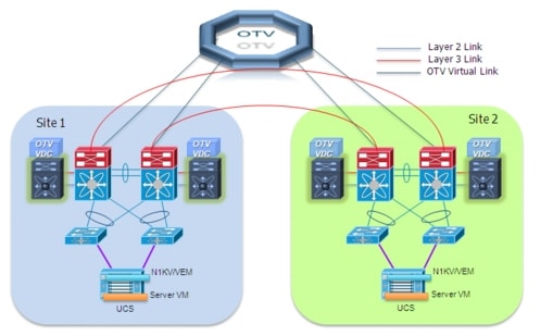
The current implementation on the Nexus 7000 enforces the separation between SVI routing and OTV encapsulation for a given VLAN. This is an important consideration for the scenario depicted above, since the Nexus 7000 aggregation switches would actually have to perform both functionalities. This separation can be achieved with the traditional workaround of having two separate network devices to perform these two functions. However, a cleaner and less intrusive solution is proposed here by introducing the use of Virtual Device Contexts (VDCs) available with Nexus 7000 platforms. Two VDCs would be deployed: an OTV VDC dedicated to perform the OTV functionalities and a Routing VDC used to provide SVI routing support.
The deployment of OTV over dark fiber brings up several design advantages when compared to the vPC-based solution previously discussed:
•![]() Provision of Layer 2 and Layer 3 connectivity leveraging the same dark fiber connections. Figure 2-5 highlights how the dark fiber connection can now be configured as routed links. This is possible because OTV encapsulated traffic generated from the OTV VDC is normal IP traffic and can be exchanged between sites leveraging a routed connection.
Provision of Layer 2 and Layer 3 connectivity leveraging the same dark fiber connections. Figure 2-5 highlights how the dark fiber connection can now be configured as routed links. This is possible because OTV encapsulated traffic generated from the OTV VDC is normal IP traffic and can be exchanged between sites leveraging a routed connection.
 |
Note |
•![]() Native failure domain isolation: there is no need to explicitly configure BPDU filtering to prevent the creation of a larger STP domain extending between the two sites. Also, ARP optimization is also provided in order to limit the amount of ARP broadcast frames exchanged between data center locations.
Native failure domain isolation: there is no need to explicitly configure BPDU filtering to prevent the creation of a larger STP domain extending between the two sites. Also, ARP optimization is also provided in order to limit the amount of ARP broadcast frames exchanged between data center locations.
•![]() Improved Layer 2 data plane isolation: The required storm-control configuration is simplified in the OTV deployment scenario because of the native suppression of unknown unicast frames and for the broadcast containment capabilities of the protocol (broadcast containment is a roadmap item at the time of writing of this document).
Improved Layer 2 data plane isolation: The required storm-control configuration is simplified in the OTV deployment scenario because of the native suppression of unknown unicast frames and for the broadcast containment capabilities of the protocol (broadcast containment is a roadmap item at the time of writing of this document).
•![]() Native multi-homing LAN extension capabilities, which would allow extending the service to additional remote sites in a very simple fashion.
Native multi-homing LAN extension capabilities, which would allow extending the service to additional remote sites in a very simple fashion.
Path Optimization
The deployment of LAN extension technologies implies that the same LAN/IP subnet gets stretched between two (or more) data center locations. As a consequence, a given IP address loses its linkage to a specific location. A mechanism is usually desired to optimize the traffic flows between any client and a specific data center service and also between server tiers (specifically for multi-layer application deployments). This is done in order to minimize the "tromboning effect" of traffic going back and forth across the LAN extension connection established between sites.
Specifically focusing on client-server communication, Figure 2-6 highlights how there are two aspects of Path Optimization to take into considerations.
Figure 2-6 Ingress and Egress Path Optimization
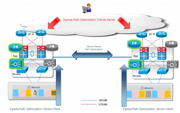
•![]() Egress Path Optimization: in order to optimize the server to client (egress) traffic flows, it is usually required to deploy a local active default gateway for all the hosts belonging to a given extended VLAN. Notice that doing so, not only ensure to optimize traffic directed toward a given client, but avoid also tromboning of traffic for inter-subnet routing inside each data center location. When deploying egress path optimization in the context of a virtualized workload mobility deployment, it is also important to ensure that the same virtual MAC (vMAC) and virtual IP (vIP) are associated to the default gateway active in each location.
Egress Path Optimization: in order to optimize the server to client (egress) traffic flows, it is usually required to deploy a local active default gateway for all the hosts belonging to a given extended VLAN. Notice that doing so, not only ensure to optimize traffic directed toward a given client, but avoid also tromboning of traffic for inter-subnet routing inside each data center location. When deploying egress path optimization in the context of a virtualized workload mobility deployment, it is also important to ensure that the same virtual MAC (vMAC) and virtual IP (vIP) are associated to the default gateway active in each location.
In this way, a workload moved between DC1 and DC2 (for example leveraging VMware vMotion) would maintain in the ARP cache the information it had before moving, so the same (vMAC, vIP) combination can be used to route traffic outside its own subnet once migrated to the new location.
The recommended solution to achieve this goal consist in defining the same FHRP (HSRP, VRRP) group in each site and filter the FHRP messaging across the LAN extension connection. This prevents the HSRP nodes in the local Data Center from communicating with the HSRP nodes in the remote Data Center and allows each HSRP group to operating independently from one another. The virtual machine IP default gateway is configured for the HSRP Virtual IP address, and since the HSRP VIP is the same in each Data Center (together with the vMAC, since the same HSRP group is configured), the VM IP default gateway does not need to change, and remains active, as the VM moves from one Data Center to another.
•![]() Ingress Path Optimization: the optimization of egress traffic flows previously described represents only half of the challenge. In many scenarios it is highly desirable to ensure optimization also for the ingress traffic flows (client to server), in order to avoid asymmetric routing scenarios where traffic directed to the client exits from DC1 and the return flows directed to the server enters through DC2. This becomes mandatory when deploying stateful services (like the FW and the load balancer shown in Ingress and Egress Path Optimization13), in order to avoid breaking established sessions once the workload is moved to the new location. The set of technologies providing this functionality are named Ingress Path Optimization technologies.
Ingress Path Optimization: the optimization of egress traffic flows previously described represents only half of the challenge. In many scenarios it is highly desirable to ensure optimization also for the ingress traffic flows (client to server), in order to avoid asymmetric routing scenarios where traffic directed to the client exits from DC1 and the return flows directed to the server enters through DC2. This becomes mandatory when deploying stateful services (like the FW and the load balancer shown in Ingress and Egress Path Optimization13), in order to avoid breaking established sessions once the workload is moved to the new location. The set of technologies providing this functionality are named Ingress Path Optimization technologies.
Egress Path Optimization
For server-client traffic flows optimization (outbound direction), it's possible to leverage functionalities like default gateway (FHRP) isolation. This FHRP isolation functionality can be achieved in different ways depending on the specific LAN extension technology deployed, as it will be discussed in the following two sections.
FHRP Isolation with vPC over Dark Fiber
To optimize the server-client flows and the local routing of traffic between different subnets, it is recommended to leverage FHRP Isolation, which allows providing an active default gateway in each location also for the subnets that are stretched between sites. This is achieved by filtering HSRP messages and avoiding the two pair of Nexus 7000 devices from exchanging them across the DCI connection (which would happen when defining the same HSRP group in both sites).
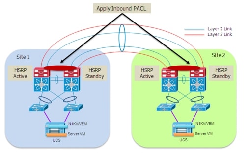
Figure 2-7 highlights the specific case where HSRP is used as First Hop Redundancy Protocol on the Nexus 7000 devices acting as default gateway for all the hosts.
Figure 2-7 HSRP Isolation across the vPC Connection
 |
Note |
The behavior shown above can be achieved by applying an inbound Port ACL on the DCI connection (logical vPC port-channel) so to be able to drop any incoming HSRP frame originated in the remote site. Notice that a VLAN ACL (VACL) defined on the aggregation Nexus 7000 switches could not be used for the same purpose, as it would also prevent the local exchange of HSRP messages between the site aggregation layer devices.
It is worth noticing how the specific Nexus 7000 hardware implementation would cause the aggregation switches to learn the HSRP vMAC from the messages received on the DCI connection before these packets can actually be dropped by the applied PACL. In the validated topology shown in Figure 2-7, this does not represent a problem, since information for this vMAC is already known locally (static entry), so the dynamic entry learned via the DCI connection is never added to the table. This is true for both HSRP Active and Standby devices, when vPC is used to connect these to the rest of the switch (HSRP behavior is improved when integrated with vPC to provide active-active data plane first-hop routing capabilities).
FHRP Isolation with OTV
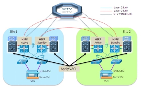
Similarly to what discussed for the vPC-based approach, it is possible to provide a specific configuration to filter HSRP messages and prevent them to be exchanged across the logical OTV overlay. The recommended approach in this case consists in defining a VLAN ACL on the OTV VDC and applying it to the set of VLANs that need to be extended. As Figure 2-8 highlights, the end result is the same as what shown for the vPC deployment, and an active/standby HSRP pair is present in each data center site.
Figure 2-8 HSRP Isolation across the OTV Overlay
A couple of additional considerations are required in this case:
•![]() The filtering of HSRP happens now before the messages are sent to the other site. This is due to the application of a VACL instead than a PACL (as already mentioned a PACL can only be applied in the inbound direction).
The filtering of HSRP happens now before the messages are sent to the other site. This is due to the application of a VACL instead than a PACL (as already mentioned a PACL can only be applied in the inbound direction).
•![]() Because of a specific Nexus 7000 HW implementation, even if the HSRP messages are dropped by the VACL once they get to the OTV VDC, this does not prevent the OTV device from learning the HSRP vMAC from the received frame. As a consequence, an OTV control protocol update is created for that vMAC and sent to the other OTV devices connected to the same overlay. Even if this behavior should not have functional impact on the solution, it is recommended to apply a simple configuration (route-map) to the OTV control plane to avoid sending this specific update.
Because of a specific Nexus 7000 HW implementation, even if the HSRP messages are dropped by the VACL once they get to the OTV VDC, this does not prevent the OTV device from learning the HSRP vMAC from the received frame. As a consequence, an OTV control protocol update is created for that vMAC and sent to the other OTV devices connected to the same overlay. Even if this behavior should not have functional impact on the solution, it is recommended to apply a simple configuration (route-map) to the OTV control plane to avoid sending this specific update.
 |
Note |
Ingress Path Optimization
For client-server flows optimization (inbound direction), an additional level of intelligence is required to provide information on which specific location the service is available and avoid a sub-optimal traffic path across the L2 connection established between sites. As mentioned, this may cause an asymmetric traffic path that would break once stateful devices (FW, load balancers, etc.) are deployed as part of the solution, as shown in Figure 2-9.
Figure 2-9 Asymmetric Traffic Behavior

The following section presents a specific DNS based ingress path optimization solution based on the integration of Cisco Application Control Engine (ACE), Cisco Global Site Selector (GSS) and VMware vCenter.
DNS Based Functionality with ACE, GSS and vCenter Integration
The specific approach validated and discussed in this document to optimize the inbound client to server traffic flows is DNS based and leverage the following components:
•![]() Cisco Global Site Selector (GSS)
Cisco Global Site Selector (GSS)
•![]() Cisco Application Control Engine (ACE), deployed as an appliance
Cisco Application Control Engine (ACE), deployed as an appliance
•![]() VMware vCenter
VMware vCenter
 |
Note |
Some of the initial design assumptions for this specific solution follow:
•![]() A separate ACE is deployed in each data center site (this could obviously be an Active/Standby HA pair for redundancy purposes). The ACE is connected to the aggregation layer devices leveraging a vPC connection ("on a stick" model).
A separate ACE is deployed in each data center site (this could obviously be an Active/Standby HA pair for redundancy purposes). The ACE is connected to the aggregation layer devices leveraging a vPC connection ("on a stick" model).
•![]() The ACE in each data center associates a different Virtual IP (VIP) address to each given workload (1:1 mapping). This implies that when the workload is deployed in DC1, external clients can access it by connecting to VIP_1 address, whereas VIP_2 is used once the workload is moved to DC2. This is the basic assumption of every DNS based ingress optimization technique, since the use of a unique VIP per site is what allows the GSS to redirect traffic to the right location where the workload is deployed.
The ACE in each data center associates a different Virtual IP (VIP) address to each given workload (1:1 mapping). This implies that when the workload is deployed in DC1, external clients can access it by connecting to VIP_1 address, whereas VIP_2 is used once the workload is moved to DC2. This is the basic assumption of every DNS based ingress optimization technique, since the use of a unique VIP per site is what allows the GSS to redirect traffic to the right location where the workload is deployed.
•![]() Source NAT (S-NAT) functionality has been validated in the solution, to ensure stitching of egress traffic back to the ACE that received the original ingress flow.
Source NAT (S-NAT) functionality has been validated in the solution, to ensure stitching of egress traffic back to the ACE that received the original ingress flow.
•![]() At least one GSS per DC should be deployed to provide redundancy. In the end-to-end architecture in Figure 2-1 each GSS is for example connected to one WAN edge device. These two GSS are configured as an Active/Standby GSSM (Global Site Selector Manager) pair and are able to respond to queries regardless of their active or standby role. It is possible to deploy additional GSS nodes simply operating as peers of the GSSM pair.
At least one GSS per DC should be deployed to provide redundancy. In the end-to-end architecture in Figure 2-1 each GSS is for example connected to one WAN edge device. These two GSS are configured as an Active/Standby GSSM (Global Site Selector Manager) pair and are able to respond to queries regardless of their active or standby role. It is possible to deploy additional GSS nodes simply operating as peers of the GSSM pair.
•![]() The validated solution requires VMware vCenter to take an action (i.e. update the entry in GSS associated to a given workload), once the vMotion for the workload is completed. In the simplest fashion, this can be done only on a single VM level. As a consequence, in the context of this discussion, each single VM is used to represent a specific application.
The validated solution requires VMware vCenter to take an action (i.e. update the entry in GSS associated to a given workload), once the vMotion for the workload is completed. In the simplest fashion, this can be done only on a single VM level. As a consequence, in the context of this discussion, each single VM is used to represent a specific application.
 |
Note |
Figure 2-10 shows the traffic behavior while the workload accessed by the client is deployed in the original Data Center 1.
Figure 2-10 Client-Server Communication via DC1
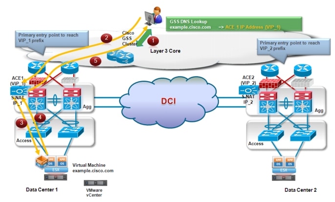
1. ![]() The client initially queries its configured DNS server for the resolution of a specific workload address (example.cisco.com). The DNS request is eventually received by the GSS that is authoritative for that specific domain and the GSS replies with the VIP address of the ACE deployed in Data Center 1 (VIP_1), since this is the only entry available for that.
The client initially queries its configured DNS server for the resolution of a specific workload address (example.cisco.com). The DNS request is eventually received by the GSS that is authoritative for that specific domain and the GSS replies with the VIP address of the ACE deployed in Data Center 1 (VIP_1), since this is the only entry available for that.
2. ![]() Traffic directed toward VIP_1 is steered toward DC1 based on routing information in the L3 core and the active ACE device receives it.
Traffic directed toward VIP_1 is steered toward DC1 based on routing information in the L3 core and the active ACE device receives it.
3. ![]() The ACE performs Source-NAT translation: the source IP is changed to an address identifying the ACE itself (an internal IP_1 address different from VIP_1); the destination IP address is left unchanged.
The ACE performs Source-NAT translation: the source IP is changed to an address identifying the ACE itself (an internal IP_1 address different from VIP_1); the destination IP address is left unchanged.
4. ![]() The workload receives the packet and replies; the packet is directed to the internal ACE IP_1 address.
The workload receives the packet and replies; the packet is directed to the internal ACE IP_1 address.
 |
Note |
5. ![]() The ACE performs the reverse translation, changing the source IP address to VIP_1 and the destination to the IP address identifying the client and sends the packet into the L3 core.
The ACE performs the reverse translation, changing the source IP address to VIP_1 and the destination to the IP address identifying the client and sends the packet into the L3 core.
Let's now assume that the workload is moved from DC1 to DC2 leveraging VMware vMotion. If this is a "live vMotion", the requirement is usually to keep the already established session still active. In scenarios like the one shown in Figure 2-10, this requirement can only be achieved by keeping the established client-server communications flowing through DC1. This is mainly because of the presence of stateful devices (like firewalls) and the fact that state is not synchronized between the pair of stateful devices in different data center sites. This means that the traffic flows for these established sessions would become the one shown in Figure 2-11.
Figure 2-11 Maintaining Client-Server Established Sessions after vMotion
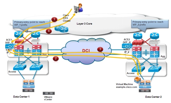
Client to server flows are still directed to VIP_1 address identifying the ACE device in DC1, hence traversing the same firewall that was used from the beginning.
1. ![]() The ACE performs S-NAT translation and is able to reach the destination server by leveraging the L2 logical path provided by the LAN extension technology of choice.
The ACE performs S-NAT translation and is able to reach the destination server by leveraging the L2 logical path provided by the LAN extension technology of choice.
2. ![]() The server responds and leveraging the LAN extension path the traffic is stitched back to the ACE in DC1 (again, this is because of the S-NAT translation happened at the previous step). It is worth noticing that if the ACE internal IP address is deployed on a separate subnet that the one where the workload resides, traffic will be first locally sent to the default gateway in DC2 and then routed (and not L2 switched) across the DCI connection to reach the ACE in DC1.
The server responds and leveraging the LAN extension path the traffic is stitched back to the ACE in DC1 (again, this is because of the S-NAT translation happened at the previous step). It is worth noticing that if the ACE internal IP address is deployed on a separate subnet that the one where the workload resides, traffic will be first locally sent to the default gateway in DC2 and then routed (and not L2 switched) across the DCI connection to reach the ACE in DC1.
3. ![]() The ACE sends the traffic back to the client.
The ACE sends the traffic back to the client.
This specific behavior applies only to the already established sessions or for new sessions initiated by clients leveraging the old DNS mapping to VIP_1. These sessions will be naturally terminated after some time, so the expectation is that there won't be need to use bandwidth of the DCI connection for this purpose anymore.
For sessions initiated by new clients, since the server is now located in DC2, the desire is to establish directly connectivity to that site, avoiding the sub-optimal path across the DCI connection. In order to achieve this, it is required to have VMware vCenter interacting with the GSS. The overall behavior is shown in Figure 2-12.
Figure 2-12 Traffic Flows Optimization after vMotion
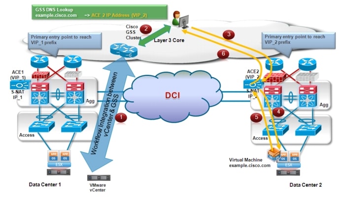
1. ![]() After the vMotion event is completed, vCenter communicates with GSS. The result is a change of the IP address associated to the specific server (example.cisco.com) from VIP_1 to VIP_2 identifying the active ACE device deployed in DC2.
After the vMotion event is completed, vCenter communicates with GSS. The result is a change of the IP address associated to the specific server (example.cisco.com) from VIP_1 to VIP_2 identifying the active ACE device deployed in DC2.
2. ![]() When a new client wants to initiate a session to the server and sends a DNS request to the GSS, the GSS replies now with the VIP_2 address.
When a new client wants to initiate a session to the server and sends a DNS request to the GSS, the GSS replies now with the VIP_2 address.
3. ![]() Traffic is steered to DC2 where the ACE identified by VIP_2 is deployed. Once again, this is because of normal routing performed in the L3 core of the network.
Traffic is steered to DC2 where the ACE identified by VIP_2 is deployed. Once again, this is because of normal routing performed in the L3 core of the network.
4. ![]() The ACE performs S-NAT as usual and sends the traffic to the server.
The ACE performs S-NAT as usual and sends the traffic to the server.
5. ![]() The server replies and the traffic is now stitched back to the ACE in DC2.
The server replies and the traffic is now stitched back to the ACE in DC2.
6. ![]() Traffic is finally sent from the ACE to the original client IP address.
Traffic is finally sent from the ACE to the original client IP address.
In summary, the key functionalities that enable path optimization leveraging the GSS, ACE and VMware vCenter components are the following:
•![]() ACEs devices deployed in different data center sites leverage unique external VIPs: this is required to ensure optimal traffic path for flows originated from the L3 core.
ACEs devices deployed in different data center sites leverage unique external VIPs: this is required to ensure optimal traffic path for flows originated from the L3 core.
•![]() Use of Source-NAT functionality on the ACE device: this ensures that return traffic flows are always brought back to the ACE used for inbound direction. This is a critical requirement to allow "stickiness" to the deployed chain of stateful services (firewalls for example), usually deployed "north" of the ACE device.
Use of Source-NAT functionality on the ACE device: this ensures that return traffic flows are always brought back to the ACE used for inbound direction. This is a critical requirement to allow "stickiness" to the deployed chain of stateful services (firewalls for example), usually deployed "north" of the ACE device.
•![]() Storage access optimization is also required, to avoid a degradation of the application behavior in scenarios where the server is forced to access the disk placed in the original site. More considerations around storage can be found in the "Storage Elasticity" section.
Storage access optimization is also required, to avoid a degradation of the application behavior in scenarios where the server is forced to access the disk placed in the original site. More considerations around storage can be found in the "Storage Elasticity" section.
Workload Mobility
The specific solution validated and documented in this document leverages VMware ESXi 4.1 hypervisor to partition a physical server into multiple secure and portable virtual machines that can run side by side. The ESXi host system kernel (vmkernel) controls access to the physical resources of the server shared by the VMs. The ESX host system ensures that the following four primary hardware resources are available to guest VMs:
•![]() Memory
Memory
•![]() Processors
Processors
•![]() Network Adapters
Network Adapters
•![]() Storage (local or remote)
Storage (local or remote)
The ESXi host virtualizes this physical hardware and presents it to the individual VMs and their associated operating system for use, a technique commonly referred to as full virtualization. A hypervisor achieves full virtualization by allowing VMs to be unaware and indifferent to the underlying physical hardware of the ESX server platform. A standard virtual hardware is presented to all VMs.
The vmkernel is a hypervisor whose primary function is to schedule and manage VM access to the physical resources of the ESXi server. This task is fundamental to the reliability and performance of the ESX virtualized machines. As shown in Figure 2-13, the ESX vmkernel creates this virtualization layer and provides the VM containers where traditional operating systems such as Windows and Linux are installed.
Figure 2-13 Generic ESX Architecture Overview
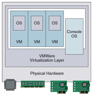
More considerations around ESXi deployment can be found in the "ESX Deployment on Cisco Unified Computing System (UCS)" section.
 |
Note |
Live vMotion Considerations
vMotion is the method used by ESX Server to migrate active VMs from one physical ESX host to another. vMotion is perhaps the most powerful feature of an ESX virtual environment, allowing the movement of active VMs with minimal downtime. Server administrators may schedule or initiate the vMotion process manually through the VMware vCenter management tool.
The vMotion process occurs in the following steps (Figure 2-14):
Figure 2-14 vMotion Process
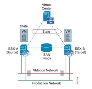
1. ![]() vCenter verifies the state of the VM and target ESX host and determines the availability of resources necessary to support the VM on the target host.
vCenter verifies the state of the VM and target ESX host and determines the availability of resources necessary to support the VM on the target host.
2. ![]() If the target host is acceptable, a copy of the active VMs state is sent from the source ESX host to the target ESX host. The state information includes memory, registers, network connections, and configuration information. This is an ongoing process until the delta between the source and target state information is nominal.
If the target host is acceptable, a copy of the active VMs state is sent from the source ESX host to the target ESX host. The state information includes memory, registers, network connections, and configuration information. This is an ongoing process until the delta between the source and target state information is nominal.
3. ![]() The source ESX server VM is suspended.
The source ESX server VM is suspended.
4. ![]() The .vmdk file (virtual disk) lock is released by the source ESX host.
The .vmdk file (virtual disk) lock is released by the source ESX host.
5. ![]() The remaining copy of state information is sent to the target ESX host.
The remaining copy of state information is sent to the target ESX host.
6. ![]() The target ESX host activates the new resident VM and simultaneously locks its associated .vmdk file.
The target ESX host activates the new resident VM and simultaneously locks its associated .vmdk file.
 |
Note |
The deployment of workload mobility using VMware vMotion between data center sites geographically separated is currently based on the following specific infrastructure requirements:
•![]() A minimum bandwidth of 1 Gbps is required when deploying vMotion inside a given data center site. In scenarios where mobility is required between disperse location (which is the main point of discussion in this document), it is mandate to provide a minimum bandwidth of 622 Mbps.
A minimum bandwidth of 1 Gbps is required when deploying vMotion inside a given data center site. In scenarios where mobility is required between disperse location (which is the main point of discussion in this document), it is mandate to provide a minimum bandwidth of 622 Mbps.
•![]() LAN extension is currently required between the data center sites where vMotion is performed. This is for two main reasons:
LAN extension is currently required between the data center sites where vMotion is performed. This is for two main reasons:
1. ![]() VMkernel interfaces are used by ESX host's internal TCP/IP stack for facilitating vMotion of a Virtual Machine between ESX hosts. At the time of writing of this document, the interfaces of the source and destination ESX servers must belong to the same IP subnet (the "vMotion Network" shown in Figure 2-14). Notice that this is not strictly a technical requirement, since vMotion traffic leverages a TCP connection (port 8000) and could hence be routed, but it is the only deployment currently officially supported by VMware.
VMkernel interfaces are used by ESX host's internal TCP/IP stack for facilitating vMotion of a Virtual Machine between ESX hosts. At the time of writing of this document, the interfaces of the source and destination ESX servers must belong to the same IP subnet (the "vMotion Network" shown in Figure 2-14). Notice that this is not strictly a technical requirement, since vMotion traffic leverages a TCP connection (port 8000) and could hence be routed, but it is the only deployment currently officially supported by VMware.
2. ![]() The IP subnet on which the virtual machine resides must be accessible from both the source and destination VMware ESX servers (this is the "Production Network" shown in Figure 2-14). This requirement is very important because a virtual machine retains its IP address when it moves to the destination VMware ESX server, to help ensure that its communication with the outside world (for example, with TCP clients) continues smoothly after the move. This is also required to allow intra-subnet communication with the devices remaining on the original site once vMotion is completed
The IP subnet on which the virtual machine resides must be accessible from both the source and destination VMware ESX servers (this is the "Production Network" shown in Figure 2-14). This requirement is very important because a virtual machine retains its IP address when it moves to the destination VMware ESX server, to help ensure that its communication with the outside world (for example, with TCP clients) continues smoothly after the move. This is also required to allow intra-subnet communication with the devices remaining on the original site once vMotion is completed
•![]() Up to the validated vSphere 4.1 version, the maximum round-trip latency between the source and destination VMware ESX servers cannot exceed 5 milliseconds. Based on the speed of light over fiber and certain guard bands for network delays, a maximum distance of 400 km is supported today (thus the specific distance of 100 Km validated for this paper is well within these boundaries).
Up to the validated vSphere 4.1 version, the maximum round-trip latency between the source and destination VMware ESX servers cannot exceed 5 milliseconds. Based on the speed of light over fiber and certain guard bands for network delays, a maximum distance of 400 km is supported today (thus the specific distance of 100 Km validated for this paper is well within these boundaries).
 |
Note |
•![]() Access from VMware vCenter (the vSphere management GUI) to both VMware ESX servers must be available to accomplish the migration. This implies that a single VMware vCenter server must span both data centers (vMotion is allowed only in the same vCenter domain).
Access from VMware vCenter (the vSphere management GUI) to both VMware ESX servers must be available to accomplish the migration. This implies that a single VMware vCenter server must span both data centers (vMotion is allowed only in the same vCenter domain).
•![]() The data storage location, including the boot device used by the virtual machine, must be active and accessible by both the source and destination VMware ESX servers at all times. If servers are present in two distinct locations, the sets of data must be identical. More considerations around the specific storage requirements can be found in the "Storage Elasticity" section.
The data storage location, including the boot device used by the virtual machine, must be active and accessible by both the source and destination VMware ESX servers at all times. If servers are present in two distinct locations, the sets of data must be identical. More considerations around the specific storage requirements can be found in the "Storage Elasticity" section.
•![]() vMotion allows to move VMs between ESX hosts in two scenarios:
vMotion allows to move VMs between ESX hosts in two scenarios:
1. ![]() Inter-clusters vMotion: the ESX hosts are grouped in two different clusters.
Inter-clusters vMotion: the ESX hosts are grouped in two different clusters.
2. ![]() Intra-cluster: the ESX hosts are all part of the same cluster.
Intra-cluster: the ESX hosts are all part of the same cluster.
•![]() Before discussing more in detail the differences between inter-cluster and intra-cluster vMotion, it is worth it mentioning the various objects required to define a virtual data center entity in vCenter.
Before discussing more in detail the differences between inter-cluster and intra-cluster vMotion, it is worth it mentioning the various objects required to define a virtual data center entity in vCenter.
Figure 2-15 Figure 22 - vCenter Objects
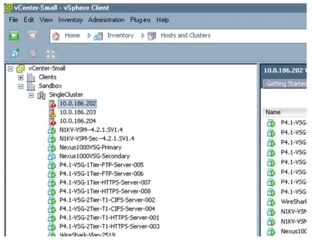
The object at the top of the hierarchy is the Datacenter (named "Sandbox" in the example above). Inside the Datacenter are then defined the various ESX hosts: as mentioned, the ESX hosts could all be part of a single cluster (like the "Single Cluster" noted above) or part of separate clusters all part of the same "Datacenter". Notice that the concept of Datacenter is completely virtual: the same virtual Datacenter may in reality leverage ESX hosts deployed in separate physical sites. Finally, the virtual machines are defined and associated to the different ESX hosts.
From a vMotion perspective, the main restriction is that a workload mobility event may only be completed between ESX hosts associated to the same virtual Datacenter. This obviously is independent from the fact that the ESX hosts are deployed in a single physical location or distributed between data center sites, and orthogonal to having the ESX hosts part of a single cluster or associated to independent clusters.
The following two sections discuss more in depth the differences between these two scenarios.
Separate VMware ESX Clusters
The deployment of a dedicated ESX cluster in each data center site is shown in Figure 2-16.
Figure 2-16 Separate ESX Clusters between Sites
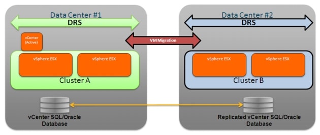
Some considerations around this type of deployment are:
•![]() Up to 32 ESX hosts can be grouped together in a cluster.
Up to 32 ESX hosts can be grouped together in a cluster.
•![]() Both clusters (Cluster A and Cluster B) must be part of the same vCenter domain and managed by the vCenter deployed in a given Data Center. There are several ways to increase the resiliency of the vCenter server; in depth discussion of these methods is out of the scope for this paper, but more information can be found at the link below:
Both clusters (Cluster A and Cluster B) must be part of the same vCenter domain and managed by the vCenter deployed in a given Data Center. There are several ways to increase the resiliency of the vCenter server; in depth discussion of these methods is out of the scope for this paper, but more information can be found at the link below:
http://kb.vmware.com/selfservice/microsites/search.do?language=en_US&cmd=displayKC&externalId=1024051
The basic assumptions for this phase of the design is that one specific method has been deployed to guarantee the liveliness of the vCenter server and that this is only deployed in a specific site (Data Center 1 in the example) to manage ESX clusters in both sites. Specific considerations on how to recover the vCenter service in case of major outage of DC1 are out of the scope for this paper.
•![]() VMware functionalities, like VMware Distributed Resource Scheduler (DRS), VMware Fault Tolerance (FT) and VMware High Availability (HA) are only available for ESX hosts belonging to the same cluster. This means that there are no chances that a Virtual Machine be dynamically moved between sites, and all the workload mobility events between Data Center A and B must be manually triggered via vCenter.
VMware functionalities, like VMware Distributed Resource Scheduler (DRS), VMware Fault Tolerance (FT) and VMware High Availability (HA) are only available for ESX hosts belonging to the same cluster. This means that there are no chances that a Virtual Machine be dynamically moved between sites, and all the workload mobility events between Data Center A and B must be manually triggered via vCenter.
•![]() In the validated vSphere 4.1 release, vMotion events between ESX hosts belonging to separate clusters could only be serialized. As discussed in the following section, parallel vMotion capabilities are only available for intra-cluster VM mobility.
In the validated vSphere 4.1 release, vMotion events between ESX hosts belonging to separate clusters could only be serialized. As discussed in the following section, parallel vMotion capabilities are only available for intra-cluster VM mobility.
•![]() In order to support vMotion, ESX hosts belonging to either Cluster A or Cluster B need to be connected to a common storage resource. More considerations around this can be found in the "Storage Elasticity" section.
In order to support vMotion, ESX hosts belonging to either Cluster A or Cluster B need to be connected to a common storage resource. More considerations around this can be found in the "Storage Elasticity" section.
Stretched VMware ESX Cluster
The deployment of a stretched ESX cluster between two data center sites is shown in Figure 2-17.
Figure 2-17 Stretched ESX Cluster between Sites
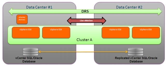
Some general considerations around this type of deployment are:
•![]() Up to 32 ESX hosts can be grouped together in a cluster
Up to 32 ESX hosts can be grouped together in a cluster
•![]() Cluster A is managed by the vCenter deployed in Data Center 1 as a specific Virtual Machine.
Cluster A is managed by the vCenter deployed in Data Center 1 as a specific Virtual Machine.
•![]() VMware functionalities, like VMware Distributed Resource Scheduler (DRS), VMware Fault Tolerance (FT) and VMware High Availability (HA) are available with this model for ESX hosts belonging to both data center sites. The consequence is that, by default, it may happen that DRS causes VMs to be dynamically moved between ESX hosts located in different sites. This behavior may not be optimal, since it may be desirable to have a tight control on when workloads are migrated across the DCI connection. One way to achieve this is obviously to disable DRS (or setting it in manual mode). Alternatively, vSphere 4.1 introduces support for "VM to Host" Affinity Rules, a feature that allows taking individual VMs or Groups of VMs and assigning them to individual ESX Servers or Groups of ESX Servers. Leveraging this functionality would allow to ensure that VMs can be dynamically moved (based on DRS driven criteria), but only between the specific set of ESX hosts belonging to the cluster but deployed in the same data center site.
VMware functionalities, like VMware Distributed Resource Scheduler (DRS), VMware Fault Tolerance (FT) and VMware High Availability (HA) are available with this model for ESX hosts belonging to both data center sites. The consequence is that, by default, it may happen that DRS causes VMs to be dynamically moved between ESX hosts located in different sites. This behavior may not be optimal, since it may be desirable to have a tight control on when workloads are migrated across the DCI connection. One way to achieve this is obviously to disable DRS (or setting it in manual mode). Alternatively, vSphere 4.1 introduces support for "VM to Host" Affinity Rules, a feature that allows taking individual VMs or Groups of VMs and assigning them to individual ESX Servers or Groups of ESX Servers. Leveraging this functionality would allow to ensure that VMs can be dynamically moved (based on DRS driven criteria), but only between the specific set of ESX hosts belonging to the cluster but deployed in the same data center site.
•![]() In the validated vSphere 4.1 release, vMotion enhancements were integrated to speed up VM migrations. On one side, improvements to vMotion functionality allow to achieve migrations that have been 8 times faster than prior releases. In addition, a support for parallel migrations was also introduced, allowing performing up to 8 coexisting migrations when leveraging a 10 GE adapter dedicated to that function on the ESX hosts.
In the validated vSphere 4.1 release, vMotion enhancements were integrated to speed up VM migrations. On one side, improvements to vMotion functionality allow to achieve migrations that have been 8 times faster than prior releases. In addition, a support for parallel migrations was also introduced, allowing performing up to 8 coexisting migrations when leveraging a 10 GE adapter dedicated to that function on the ESX hosts.
•![]() To support vMotion, ESX hosts belonging to Cluster A need to be connected to a common storage resource. More considerations around this can be found in the "Storage Elasticity" section.
To support vMotion, ESX hosts belonging to Cluster A need to be connected to a common storage resource. More considerations around this can be found in the "Storage Elasticity" section.
Stretched Nexus 1000V Model
The Cisco Nexus 1000V switch is a software switch on a server that delivers Cisco VN-Link services to virtual machines hosted on that server. It takes advantage of the VMware vSphere framework to offer tight integration between server and network environments and help ensure consistent, policy-based network capabilities to all servers in the data center.
Figure 2-18 Nexus 1000V Solution Components

Nexus 1000V allows policy to move with a virtual machine during live migration, ensuring persistent network, security, and storage compliance, resulting in improved business continuance, performance management, and security compliance. Last but not least, it aligns management of the operational environment for virtual machines and physical server connectivity in the data center, reducing the total cost of ownership (TCO) by providing operational consistency and visibility throughout the network. It offers flexible collaboration between the server, network, security, and storage teams while supporting various organizational boundaries and individual team autonomy.
The Cisco Nexus 1000V Series comprises two components:
•![]() Virtual Ethernet Module (VEM), a software switch embedded in the VMware ESX hypervisor. When comparing the N1KV virtual switch to a physical modular switch (like the Nexus 7000), each VEM can be thought as a physical linecard. Unlike multiple line cards within a single chassis, each VEM acts as an independent switch from a forwarding perspective. For what concerns scalability values, at the time of writing of this document up to 64 VEMs and 2048 virtual Ethernet (vEth) ports can be supported as part of the same virtual switch instance. It is worth noticing that this does not necessarily mean that 2048 virtual machines can be "attached" to a virtual switch instance, since usually more than one vNIC is defined on each VM (and a 1:1 static mapping between vEth and vNIC is performed when the VM is connected to the N1KV switch).
Virtual Ethernet Module (VEM), a software switch embedded in the VMware ESX hypervisor. When comparing the N1KV virtual switch to a physical modular switch (like the Nexus 7000), each VEM can be thought as a physical linecard. Unlike multiple line cards within a single chassis, each VEM acts as an independent switch from a forwarding perspective. For what concerns scalability values, at the time of writing of this document up to 64 VEMs and 2048 virtual Ethernet (vEth) ports can be supported as part of the same virtual switch instance. It is worth noticing that this does not necessarily mean that 2048 virtual machines can be "attached" to a virtual switch instance, since usually more than one vNIC is defined on each VM (and a 1:1 static mapping between vEth and vNIC is performed when the VM is connected to the N1KV switch).
•![]() Virtual Supervisor Module (VSM), which manages networking policies and quality of service for virtual machines in concert with the VEM. Repeating the previous analogy, the VSM represents the switch supervisor establishing control plane communication with the various VEMs (the "linecards"). The Cisco Nexus 1000V Series requires a VSM high-availability deployment model much like dual supervisors in a physical chassis. Two VSMs are deployed in an active-standby configuration, with the first VSM functioning in the primary role and the other VSM functioning in a secondary role. If the primary VSM fails, the secondary VSM will take over. Note that unlike in cross-bar-based modular switching platforms, the VSM is not in the data path. General data packets are not forwarded to the VSM to be processed, but rather switched by the VEM directly.
Virtual Supervisor Module (VSM), which manages networking policies and quality of service for virtual machines in concert with the VEM. Repeating the previous analogy, the VSM represents the switch supervisor establishing control plane communication with the various VEMs (the "linecards"). The Cisco Nexus 1000V Series requires a VSM high-availability deployment model much like dual supervisors in a physical chassis. Two VSMs are deployed in an active-standby configuration, with the first VSM functioning in the primary role and the other VSM functioning in a secondary role. If the primary VSM fails, the secondary VSM will take over. Note that unlike in cross-bar-based modular switching platforms, the VSM is not in the data path. General data packets are not forwarded to the VSM to be processed, but rather switched by the VEM directly.
 |
Note |
The active/standby VSMs and the VEMs are linked together as part of the same virtual switch instance leveraging the concept of "domain ID". A domain ID is a parameter of the Cisco Nexus 1000V Series Switch that is used to identify a VSM and VEM as relating to one another. Each command sent by the VSM to any associated VEMs is tagged with this domain ID and if the same domain ID is shared by a VSM and a VEM, the VEM will accept and respond to requests and commands from the VSM. If the VEM receives a command or configuration request that is not tagged with the correct domain ID, that request is ignored. Similarly, if the VSM receives a packet from a VEM that is tagged with the wrong domain ID, the packet will be ignored.
Finally, the Cisco Nexus 1000V Series provides a feature called "port profiles", as the primary mechanism by which a network policy is defined and applied to switch interfaces. A port profile is a collection of interface-level configuration commands that are combined to create a complete network policy. The port profile concept is new, but the configurations in port profiles use the same Cisco syntax used to manage switch ports on traditional switches, allowing for the configuration of network parameters as VLAN IDs, QoS attributes, etc. Port profiles create a virtual boundary between server and network administrators, since they are network policies defined by the network administrator and exported to VMware vCenter Server. Within VMware vCenter
Server, port profiles appear as VMware port groups in the same locations as traditional VMware port groups would, so that they become available for use by the server administrator within a few seconds.
 |
Note |
In the context of virtualized workload mobility, the main goal of the validation is to allow the deployment of the Nexus 1000V Distributed Virtual Switch (DVS) in a stretched fashion between Data Center physical sites. This can be achieved independently from the specific ESX cluster deployment previously discussed. This means that the VEM modules forming a given Nexus 1000V switch can be deployed on ESX hosts belonging to separate ESX clusters (Figure 2-16) or to a common cluster (Figure 2-17).
Figure 2-19, for example, highlights the deployment of Nexus 1000V between sites in conjunction with a separate VMware ESX clusters model.
Figure 2-19 Nexus 1000V Deployment with Separate ESX Clusters Model
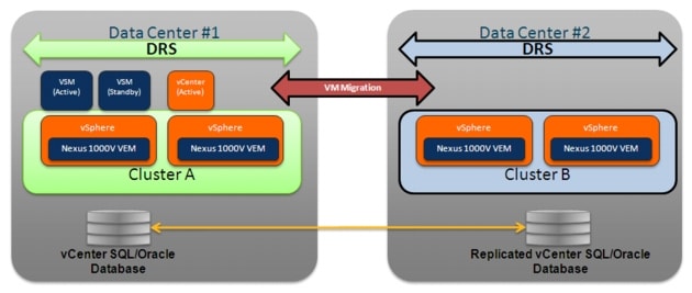
Some characteristics of this specific solution are the following:
•![]() VSM deployment: both active and standby VSMs are positioned in the same Data Center site. This is the only recommended and supported option at the time of writing of this document to avoid the possibility of an "active-active" scenario, where both VSM are activated in different sites as a consequence of a complete failure of the DCI connection causing network isolation between sites.
VSM deployment: both active and standby VSMs are positioned in the same Data Center site. This is the only recommended and supported option at the time of writing of this document to avoid the possibility of an "active-active" scenario, where both VSM are activated in different sites as a consequence of a complete failure of the DCI connection causing network isolation between sites.
 |
Note |
•![]() The deployment of Nexus 1010 as a container of the VSMs is not considered as part of this validation effort. As a consequence, both active and standby VSMs were deployed as Virtual Machines belonging to an ESX host. It is recommended to deploy each VSM in an active-standby pair on a separate VMware ESX host. This requirement helps ensure high availability even if one of the VMware ESX servers fails. The anti-affinity option in VMware ESX can also be deployed to help keeping the VSMs on different servers. Notice that this is a feature complementary to the one introduced with vSphere 4.1 and targeted to "VM to Host" affinity rules previously discussed.
The deployment of Nexus 1010 as a container of the VSMs is not considered as part of this validation effort. As a consequence, both active and standby VSMs were deployed as Virtual Machines belonging to an ESX host. It is recommended to deploy each VSM in an active-standby pair on a separate VMware ESX host. This requirement helps ensure high availability even if one of the VMware ESX servers fails. The anti-affinity option in VMware ESX can also be deployed to help keeping the VSMs on different servers. Notice that this is a feature complementary to the one introduced with vSphere 4.1 and targeted to "VM to Host" affinity rules previously discussed.
•![]() It is worth noticing that the VSM used to manage the various VEMs was deployed as a virtual machine connected to the same VEM module it needs to manage. As discussed in "ESX Deployment on Cisco Unified Computing System (UCS)", the use of specific "system VLANs" allows this model to work breaking a potential "chicken-and-egg" situation.
It is worth noticing that the VSM used to manage the various VEMs was deployed as a virtual machine connected to the same VEM module it needs to manage. As discussed in "ESX Deployment on Cisco Unified Computing System (UCS)", the use of specific "system VLANs" allows this model to work breaking a potential "chicken-and-egg" situation.
•![]() L3 is the chosen transport mode for control plane traffic between the active VSM and the distributed VEMs (as opposed to the L2 option). There are a couple of advantages in selecting this approach:
L3 is the chosen transport mode for control plane traffic between the active VSM and the distributed VEMs (as opposed to the L2 option). There are a couple of advantages in selecting this approach:
1. ![]() Management VLAN/IP subnet can be used for connectivity between VSM and VEMs removing the requirement for a separate VLAN
Management VLAN/IP subnet can be used for connectivity between VSM and VEMs removing the requirement for a separate VLAN
2. ![]() L3 allows VEMs to be located in different physical location where L2?adjacency might be challenging
L3 allows VEMs to be located in different physical location where L2?adjacency might be challenging
When deploying L3 transport mode, control plane packets exchanged between the active VSM and the VEMs are GRE encapsulated. On the VSM side, a specific "control 0" interface gets automatically created once L3 transport mode is selected. An IP address is then assigned to such interface to communicate with all the distributed VEMs (a specific VMkernel interface on the ESX server hosting the VEM is used for this purpose).
•![]() The control plane is used to handle low-level control packets (such as heartbeats) as well as any configuration data that needs to be exchanged between the VSM and the VEMs. Because of the nature of the traffic carried over the control plane connection, it is recommended to prioritize this traffic to help ensure that the control packets are not dropped. This is even more relevant when stretching the deployment of N1KV between remote sites, since the same DCI connection can be used for various types of communications.
The control plane is used to handle low-level control packets (such as heartbeats) as well as any configuration data that needs to be exchanged between the VSM and the VEMs. Because of the nature of the traffic carried over the control plane connection, it is recommended to prioritize this traffic to help ensure that the control packets are not dropped. This is even more relevant when stretching the deployment of N1KV between remote sites, since the same DCI connection can be used for various types of communications.
•![]() DCI connection failure: the deployment of Nexus 1000V stretched between data center sites raises some questions on the system behavior under the specific circumstances of DCI connection outage, which leads to isolating the two physical locations. As mentioned, the first recommendation is to deploy both the active and standby VSMs in the same site, to avoid split-brain scenarios. However, it is important also to consider the interactions between the other functional components, as for example:
DCI connection failure: the deployment of Nexus 1000V stretched between data center sites raises some questions on the system behavior under the specific circumstances of DCI connection outage, which leads to isolating the two physical locations. As mentioned, the first recommendation is to deploy both the active and standby VSMs in the same site, to avoid split-brain scenarios. However, it is important also to consider the interactions between the other functional components, as for example:
–![]() VSM-VEM communication: starting with software release 4.2(1)SV1(2), heartbeat messages are exchanged every second between the active VSM and the VEMs. If the DCI connection fails, VEMs in the remote site lose communication to the VSM (there is a specific timeout timer of 6 seconds to determine this case). Once the DCI connection is restored and the VEMs reconnect to the active VSM, assuming no changes have been made on the VSM during the outage period, the VEMs do not need to be reprogrammed and hitless reconnection is experienced. If however the admin has made changes on the VSM while the VEMs were disconnected, then there may be up to 15 seconds pause in network traffic while the VEM are reprogrammed once the connectivity is re-established. As a consequence, the recommendation is to ensure no changes are made if the VEM(s) are not connected to the VSM.
VSM-VEM communication: starting with software release 4.2(1)SV1(2), heartbeat messages are exchanged every second between the active VSM and the VEMs. If the DCI connection fails, VEMs in the remote site lose communication to the VSM (there is a specific timeout timer of 6 seconds to determine this case). Once the DCI connection is restored and the VEMs reconnect to the active VSM, assuming no changes have been made on the VSM during the outage period, the VEMs do not need to be reprogrammed and hitless reconnection is experienced. If however the admin has made changes on the VSM while the VEMs were disconnected, then there may be up to 15 seconds pause in network traffic while the VEM are reprogrammed once the connectivity is re-established. As a consequence, the recommendation is to ensure no changes are made if the VEM(s) are not connected to the VSM.
–![]() VSM-vCenter communication: the connection between VSM and vCenter is normally used to propagate new port profiles information and any changes to existing port profiles. If the connection between the VSM and VMware vCenter Server is disrupted, the VSM helps ensure that any configuration changes that have been made during this period of disrupted communication are propagated to VMware vCenter Server when the link is restored. However, this scenario should be pretty unusual given the fact that both active/standby VSMs and vCenter are normally deployed in the same data center site.
VSM-vCenter communication: the connection between VSM and vCenter is normally used to propagate new port profiles information and any changes to existing port profiles. If the connection between the VSM and VMware vCenter Server is disrupted, the VSM helps ensure that any configuration changes that have been made during this period of disrupted communication are propagated to VMware vCenter Server when the link is restored. However, this scenario should be pretty unusual given the fact that both active/standby VSMs and vCenter are normally deployed in the same data center site.
–![]() VEM-vCenter communication: when a new VEM comes online, either after initial installation or upon restart of a VMware ESX host, it is essentially an un-programmed line card. To be correctly configured, the VEM needs to communicate with the VSM and this process is facilitated by VMware vCenter Server that automatically sends specific information (called "opaque data") to the VEM, which the VEM uses to establish communication with the VSM and download the appropriate configuration data. The implications of this process, is that VEMs deployed in a remote site cannot be brought up online during the outage of the DCI connection. However, the process will be able to complete as soon as the DCI connection is recovered and VEMs connectivity with vCenter can be re-established.
VEM-vCenter communication: when a new VEM comes online, either after initial installation or upon restart of a VMware ESX host, it is essentially an un-programmed line card. To be correctly configured, the VEM needs to communicate with the VSM and this process is facilitated by VMware vCenter Server that automatically sends specific information (called "opaque data") to the VEM, which the VEM uses to establish communication with the VSM and download the appropriate configuration data. The implications of this process, is that VEMs deployed in a remote site cannot be brought up online during the outage of the DCI connection. However, the process will be able to complete as soon as the DCI connection is recovered and VEMs connectivity with vCenter can be re-established.
•![]() Network policies enforced by a port profile follow the virtual machine throughout its lifecycle, whether the virtual machine is being migrated from one server to another, suspended, hibernated, or restarted. This is particularly relevant in a virtualized workload mobility solution, where the VM is migrated between data center sites. In addition to migrating the policy, the Cisco Nexus 1000V Series moves the virtual machine's network state, such as the port counters and flow statistics. Virtual machines participating in traffic monitoring activities, such as Cisco NetFlow or Encapsulated Remote Switched Port Analyzer (ERSPAN), can continue these activities uninterrupted by vMotion operations.
Network policies enforced by a port profile follow the virtual machine throughout its lifecycle, whether the virtual machine is being migrated from one server to another, suspended, hibernated, or restarted. This is particularly relevant in a virtualized workload mobility solution, where the VM is migrated between data center sites. In addition to migrating the policy, the Cisco Nexus 1000V Series moves the virtual machine's network state, such as the port counters and flow statistics. Virtual machines participating in traffic monitoring activities, such as Cisco NetFlow or Encapsulated Remote Switched Port Analyzer (ERSPAN), can continue these activities uninterrupted by vMotion operations.
•![]() Migration procedure for VSMs: in some specific scenarios (maintenance, disaster avoidance procedures, etc.) it may be required to migrate a VSM virtual machine between ESX hosts. If this is performed inside the same data center location (maintenance use case), no specific considerations are required. If however the migration is performed between ESX host deployed in separate sites (disaster avoidance use case), it becomes important to ensure that the migration procedure is performed in a specific fashion, to avoid the potential issue of ending up at a given time with an active and standby VSM part of two separate sites. This would expose the solution to the dual-active issue, should the DCI connection fail right in that moment. The recommended migration procedure is the following:
Migration procedure for VSMs: in some specific scenarios (maintenance, disaster avoidance procedures, etc.) it may be required to migrate a VSM virtual machine between ESX hosts. If this is performed inside the same data center location (maintenance use case), no specific considerations are required. If however the migration is performed between ESX host deployed in separate sites (disaster avoidance use case), it becomes important to ensure that the migration procedure is performed in a specific fashion, to avoid the potential issue of ending up at a given time with an active and standby VSM part of two separate sites. This would expose the solution to the dual-active issue, should the DCI connection fail right in that moment. The recommended migration procedure is the following:
1. ![]() For the duration the following events take place, do not bring up any new VMs or vMotion other VMs.
For the duration the following events take place, do not bring up any new VMs or vMotion other VMs.
2. ![]() Power off the standby VSM and migrate it from the first site to the second site.
Power off the standby VSM and migrate it from the first site to the second site.
3. ![]() Perform a storage vMotion for the standby VSM storage (if storage vMotion is needed).
Perform a storage vMotion for the standby VSM storage (if storage vMotion is needed).
4. ![]() Migrate the original active VSM from the first site to the second site.
Migrate the original active VSM from the first site to the second site.
5. ![]() Perform a storage vMotion for the original active VSM storage (if storage vMotion is needed).
Perform a storage vMotion for the original active VSM storage (if storage vMotion is needed).
6. ![]() Power on the standby VSM and reform an HA-pair.
Power on the standby VSM and reform an HA-pair.
 |
Note |
When performing the migration procedure detailed above, it is important to keep in mind that the VLAN where the active/standby VSMs are deployed in DC1 needs to be extended across the DCI connection to exist also in DC2. This is to allow these virtual machines network connectivity once the vMotion process is completed. This is required independently from the transport type (L2 or L3) used for control plane communication between the active VSM and the distributed VEMs.
ESX Deployment on Cisco Unified Computing System (UCS)
The Cisco Unified Computing System allows for the establishment of a server farm architecture that enables system resources to be allocated dynamically and flexibly to meet individual virtual machine requirements within a common, consistent resource pool. It provides a system built on a low-latency, lossless, 10-Gbps unified network fabric. The result is rapid deployment and movement of workloads without the need to be concerned about application or virtual placement. Blade servers in the Cisco UCS 5108 Blade Server Chassis have access to the fabric through mezzanine-card adapters that provide up to 40 Gbps of throughput per blade server.
The unified fabric enables a "wire once" deployment model in which chassis are cabled to the fabric interconnects just one time, and I/O configuration changes are made through the management system, unlike solutions that require installation of host adapters and recabling of racks and switches (Figure 2-20). A unified fabric dramatically simplifies rack cabling by eliminating the need for multiple redundant Ethernet and Fibre Channel adapters in each server, eliminating the need for separate cabling to each access-layer switch and the need for separate switches for each network medium. With unified fabric, all traffic is routed to the central server interconnects, where Ethernet and Fibre Channel are separated onto native, nonconsolidated networks.
Figure 2-20 shows the physical cabling infrastructure required to interconnect an UCS system to the first upstream pair of network devices.
Figure 2-20 UCS Connections
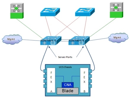
Each blade inside the UCS chassis is equipped with one (or more, depending on the blade model) Converged Network Adapter (CNA), a type of port adapter that provides both Ethernet and Fibre Channel (FC) connectivity over a 10 GE interface. Different types of CNA adapters are supported with the UCS blades. In the rest of this section only a specific adapter named Cisco UCS M81KR Virtual Interface Card (VIC) will be considered because of the enhanced functionalities it provides in virtualized environments. Each CNA is then connected to two Fabric Extender modules (FEX), inserted in the blade enclosure and logically part of the fabric switch (they are logical extension of each Fabric Interconnect device). Each FEX has four interfaces to connect to the upstream 6100 series Fabric Interconnect and carry upstream both FC and Ethernet traffic.
The 6100 Fabric Interconnect is one of the most important elements of the Cisco Unified Computing System. It contains all the combined network and server configuration settings, policies, resource pools, and templates, and it provides a single management interface for rapid network and computing service provisioning. At the 6100 level is also possible to separate Ethernet traffic (carried to the upstream network devices) and FC traffic (carried toward the storage fabric).
The Fabric Interconnect connects to the UCS Chassis leveraging interfaces defined "Server Ports". It also connects to the Ethernet switches upstream via "Uplink Ports" and to the SAN switches via "SAN Ports". Finally, each Fabric Interconnect is connected to the management network via a dedicated interface; this is to access the UCS Manager running on the Fabric Interconnect and used to manage the entire UCS system. Special cluster links are also used to interconnect the Fabric Interconnects devices: these are point-to-point GE links used to create the Fabric Interconnect cluster, synchronize the configuration and state between the two fabrics and are never used for data path traffic.
 |
Note |
Different level of virtualization capabilities are provided in a UCD System, as highlighted in Figure 2-21.
Figure 2-21 Virtualization Capabilities of the UCS System
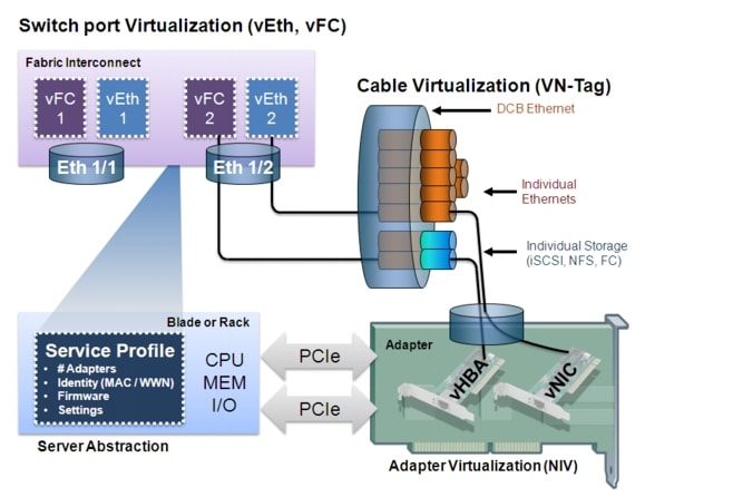
•![]() Server virtualization: there are physical servers (UCS B series blades or C series rack mount servers), but their configuration is defined in a Service Profile held in a database in the Fabric Interconnect device (it is an XML entry in the database). The Service Profile defines all of the settings of the server: number of adapters (NICs, HBAs), identity of the adapters (MAC address, WWNs), firmware of the adapters and of the server, setting of the server, etc. The Service Profile can then be applied to any blade server or rack mount server and even moved between these entities.
Server virtualization: there are physical servers (UCS B series blades or C series rack mount servers), but their configuration is defined in a Service Profile held in a database in the Fabric Interconnect device (it is an XML entry in the database). The Service Profile defines all of the settings of the server: number of adapters (NICs, HBAs), identity of the adapters (MAC address, WWNs), firmware of the adapters and of the server, setting of the server, etc. The Service Profile can then be applied to any blade server or rack mount server and even moved between these entities.
•![]() Adapter virtualization: the Cisco UCS M81KR presents up to 128 virtual interfaces to the operating system on a given blade. The virtual interfaces are dynamically configured by Cisco UCS Manager as either Fibre Channel or Ethernet devices. vNICs and vHBAs connect via "virtual cables" through the physical adapter. A server scanning the PCI bus will discover these virtual adapters as if they were adapters physically plugged in the PCI bus. The provisioning of virtual adapters happens automatically based on the information stored in the Service Profile.
Adapter virtualization: the Cisco UCS M81KR presents up to 128 virtual interfaces to the operating system on a given blade. The virtual interfaces are dynamically configured by Cisco UCS Manager as either Fibre Channel or Ethernet devices. vNICs and vHBAs connect via "virtual cables" through the physical adapter. A server scanning the PCI bus will discover these virtual adapters as if they were adapters physically plugged in the PCI bus. The provisioning of virtual adapters happens automatically based on the information stored in the Service Profile.
•![]() Cable virtualization: use of the VN-Tag technology allows differentiating traffic generated from each virtual adapter (vNICs, vHBAs). The provisioning of these virtual connections happens automatically based on the information stored in the Service Profile.
Cable virtualization: use of the VN-Tag technology allows differentiating traffic generated from each virtual adapter (vNICs, vHBAs). The provisioning of these virtual connections happens automatically based on the information stored in the Service Profile.
•![]() Switch Port Virtualization: the Fabric Interconnect is the physical switch for the entire UCS system and it leverages physical interfaces (called "Server Ports") to connect to UCS Chassis or rack mount blade servers. Each physical Server Port provides physical connectivity for the virtual FC and Ethernet interfaces defined on the Fabric Interconnect. These virtual interfaces are then connected to the virtual adapters defined on the servers leveraging the VN-Tag capabilities.
Switch Port Virtualization: the Fabric Interconnect is the physical switch for the entire UCS system and it leverages physical interfaces (called "Server Ports") to connect to UCS Chassis or rack mount blade servers. Each physical Server Port provides physical connectivity for the virtual FC and Ethernet interfaces defined on the Fabric Interconnect. These virtual interfaces are then connected to the virtual adapters defined on the servers leveraging the VN-Tag capabilities.
The network diagram in Figure 2-22 highlights the way the Cisco Unified Computing System (UCS) was deployed at the server layer of the validated architecture and connected directly to a pair of Nexus 7000 switches representing the collapsed DC access/aggregation layer.
Figure 2-22 UCS Connectivity to Nexus 7000 in the Validated Topology
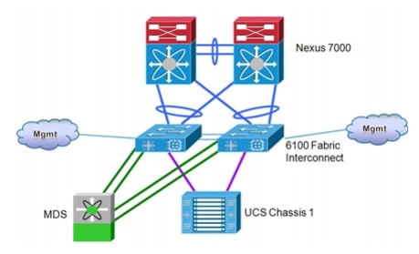
 |
Note |
Some design considerations around this specific deployment model are:
•![]() The 6100 Fabric Interconnect devices are deployed in end-host mode, which represents the recommended option when compared to the switch mode of operation. Some of the characteristics of end-host mode are the following:
The 6100 Fabric Interconnect devices are deployed in end-host mode, which represents the recommended option when compared to the switch mode of operation. Some of the characteristics of end-host mode are the following:
–![]() The Fabric Interconnect provides local Layer 2 switching for all server ports in the Unified Computing System. This essentially means that Layer 2 communication between hosts deployed on separate UCS chassis can be performed at the 6100 layer, without requiring the traffic to be sent toward the upstream Nexus 7000 devices.
The Fabric Interconnect provides local Layer 2 switching for all server ports in the Unified Computing System. This essentially means that Layer 2 communication between hosts deployed on separate UCS chassis can be performed at the 6100 layer, without requiring the traffic to be sent toward the upstream Nexus 7000 devices.
–![]() Local switching between uplinks port is not allowed in end-host mode. This is the key behavior that allows avoiding the creation of spanning-tree loops without running STP on the 6100 devices.
Local switching between uplinks port is not allowed in end-host mode. This is the key behavior that allows avoiding the creation of spanning-tree loops without running STP on the 6100 devices.
–![]() MAC address learning occurs only on server ports, not on uplink ports. The fabric interconnect learns and stores only MAC addresses that are located within the system, such as the addresses of the physical servers in the blade chassis and any virtual servers the physical servers may be hosting. When the fabric interconnect receives a frame from a server destined for a MAC address that cannot be found in its local MAC address table, it assumes that the destination must be outside the system and will send the frame to the server's uplinks. This behavior represents a big benefit from a scalability point of view, since it implies that the fabric interconnect MAC address table size is independent from the size of the MAC tables of the other DC switches belonging to common L2 domains.
MAC address learning occurs only on server ports, not on uplink ports. The fabric interconnect learns and stores only MAC addresses that are located within the system, such as the addresses of the physical servers in the blade chassis and any virtual servers the physical servers may be hosting. When the fabric interconnect receives a frame from a server destined for a MAC address that cannot be found in its local MAC address table, it assumes that the destination must be outside the system and will send the frame to the server's uplinks. This behavior represents a big benefit from a scalability point of view, since it implies that the fabric interconnect MAC address table size is independent from the size of the MAC tables of the other DC switches belonging to common L2 domains.
•![]() Each 6100 fabric interconnect device is connected to the upstream Nexus 7000 leveraging a logical port-channel interface. This is possible leveraging the vPC functionalities available on the Nexus 7000 switches. This connectivity choice brings the following advantages:
Each 6100 fabric interconnect device is connected to the upstream Nexus 7000 leveraging a logical port-channel interface. This is possible leveraging the vPC functionalities available on the Nexus 7000 switches. This connectivity choice brings the following advantages:
–![]() Provides higher availability and faster failover if a link or switch is taken out of service. Recovery is exclusively dependent on port-channel re-hashing (a single logical uplink is available from each 6100 to connect to the upstream switch).
Provides higher availability and faster failover if a link or switch is taken out of service. Recovery is exclusively dependent on port-channel re-hashing (a single logical uplink is available from each 6100 to connect to the upstream switch).
–![]() Increased bandwidth and improved traffic load balancing: all traffic leaving the 6100 device in upstream direction is forwarded to the logical port-channel interface. This allows providing flow-based load balancing toward the upstream network devices.
Increased bandwidth and improved traffic load balancing: all traffic leaving the 6100 device in upstream direction is forwarded to the logical port-channel interface. This allows providing flow-based load balancing toward the upstream network devices.
–![]() vPC uplinks also offer the benefit of consistent latency and deterministic traffic patterns for flows between servers belonging to separate UCS chassis. This is because each 6100 device always has a local link connecting to the server port of each UCS chassis (except under specific link failure scenarios). This means that the vPC peer-link does not need to be utilized for this type of traffic.
vPC uplinks also offer the benefit of consistent latency and deterministic traffic patterns for flows between servers belonging to separate UCS chassis. This is because each 6100 device always has a local link connecting to the server port of each UCS chassis (except under specific link failure scenarios). This means that the vPC peer-link does not need to be utilized for this type of traffic.
When discussing more in detail the deployment of the ESX hypervisor on UCS systems with the integration of Nexus 1000V virtual switch, additional important design points need to be considered (Figure 2-23).
Figure 2-23 ESXi 4.1 Deployment with Nexus 1000V on Cisco UCS

•![]() The Cisco VIC card allows presenting multiple adapters to the vSphere hypervisor in an effort to preserve the design usually achieved with bare metal servers (leveraging multiple NICs and HBAs). Up to 6 virtual adapters can be currently exposed to each ESXi server; the example in figure above shows a scenario with 4 vNICs and 2 vHBAs. This allows using a familiar VMware multi-NIC design on a server that in reality has (2) 10GE physical interfaces with complete Quality of Service, bandwidth sharing, and VLAN portability among the virtual adapters.
The Cisco VIC card allows presenting multiple adapters to the vSphere hypervisor in an effort to preserve the design usually achieved with bare metal servers (leveraging multiple NICs and HBAs). Up to 6 virtual adapters can be currently exposed to each ESXi server; the example in figure above shows a scenario with 4 vNICs and 2 vHBAs. This allows using a familiar VMware multi-NIC design on a server that in reality has (2) 10GE physical interfaces with complete Quality of Service, bandwidth sharing, and VLAN portability among the virtual adapters.
•![]() The vNICs and vHBAs discovered by the ESXi hypervisor can then be mapped to N1KV interfaces leveraging different port profiles. Still referencing the example above, a port profile called "VM Uplink" has associated the Cisco adapter vNIC1 and vNIC2, vNIC3 is associated to the "vMotion Uplink" Profile and vNIC4 is finally used for management traffic. The "VM Uplink" port profile is configured to only forward VLANs belonging to the defined virtual machines (as for example the VM attached to vEth1 interface); the "System-Uplink" port profile is configured instead to only forward VLANs belonging to management traffic. A dedicated port-profile is used for the VMkernel interface used for vMotion. The idea is to assign a dedicated vNIC on the VIC adapter for this type of traffic to be able to clearly identify it. Two vHBAs are also usually deployed to allow the ESX hosts to connect to two separate SAN fabrics (as previously shown in Figure 2-20).
The vNICs and vHBAs discovered by the ESXi hypervisor can then be mapped to N1KV interfaces leveraging different port profiles. Still referencing the example above, a port profile called "VM Uplink" has associated the Cisco adapter vNIC1 and vNIC2, vNIC3 is associated to the "vMotion Uplink" Profile and vNIC4 is finally used for management traffic. The "VM Uplink" port profile is configured to only forward VLANs belonging to the defined virtual machines (as for example the VM attached to vEth1 interface); the "System-Uplink" port profile is configured instead to only forward VLANs belonging to management traffic. A dedicated port-profile is used for the VMkernel interface used for vMotion. The idea is to assign a dedicated vNIC on the VIC adapter for this type of traffic to be able to clearly identify it. Two vHBAs are also usually deployed to allow the ESX hosts to connect to two separate SAN fabrics (as previously shown in Figure 2-20).
•![]() Each virtual adapter has its own unique VN-Tag assigned by UCS Manager. Traffic received by the physical adapter on the shared 10GE cable is associated to each defines virtual interface (vNIC or vHBA) based on the VN-Tag used. This mechanism also allows the upstream Fabric Interconnect device to identify which virtual adapter the traffic was received from and apply a unique policy to it.
Each virtual adapter has its own unique VN-Tag assigned by UCS Manager. Traffic received by the physical adapter on the shared 10GE cable is associated to each defines virtual interface (vNIC or vHBA) based on the VN-Tag used. This mechanism also allows the upstream Fabric Interconnect device to identify which virtual adapter the traffic was received from and apply a unique policy to it.
•![]() In the diagram above the UCS blade is running the Nexus 1000V VSM in a virtual machine connected to a VEM managed by the VSM itself. In order to make this model working (avoiding the mentioned "chicken-and-egg" scenario), the concept of "System VLANs" is introduced. These special VLANs should be allowed on the System port profile and have the characteristic of being up and forwarding prior to connecting with the VSM for `critical connections' such those needed to reach the VSM and other critical VMware management ports such as the VM Kernel.
In the diagram above the UCS blade is running the Nexus 1000V VSM in a virtual machine connected to a VEM managed by the VSM itself. In order to make this model working (avoiding the mentioned "chicken-and-egg" scenario), the concept of "System VLANs" is introduced. These special VLANs should be allowed on the System port profile and have the characteristic of being up and forwarding prior to connecting with the VSM for `critical connections' such those needed to reach the VSM and other critical VMware management ports such as the VM Kernel.
 |
Note |
•![]() Finally, in this design the interfaces part of the "VM Uplink" port profile are configured as part of a port-channel. The interesting design point is that each virtual interface part of this bundle is actually connected to an independent upstream Fabric Interconnect device. In order for this to work, it is required to configure the Nexus 1000V to operate in vPC Host Mode (vPC-HM). That means that the Nexus 1000V VEM learns via CDP that Eth 1/1 and Eth 1/2 are connected to separate physical switches and creates a "Sub Group" unique to each physical switch (so that if there are multiple links to the same physical switch they will be added to the same Sub Group). When a virtual machine is sending network traffic the Nexus 1000V will first pick a Sub Group and pin that VM to it. If there are multiple links within the chosen Sub Group the Nexus 1000V will load balance traffic across those links on a per-flow basis.
Finally, in this design the interfaces part of the "VM Uplink" port profile are configured as part of a port-channel. The interesting design point is that each virtual interface part of this bundle is actually connected to an independent upstream Fabric Interconnect device. In order for this to work, it is required to configure the Nexus 1000V to operate in vPC Host Mode (vPC-HM). That means that the Nexus 1000V VEM learns via CDP that Eth 1/1 and Eth 1/2 are connected to separate physical switches and creates a "Sub Group" unique to each physical switch (so that if there are multiple links to the same physical switch they will be added to the same Sub Group). When a virtual machine is sending network traffic the Nexus 1000V will first pick a Sub Group and pin that VM to it. If there are multiple links within the chosen Sub Group the Nexus 1000V will load balance traffic across those links on a per-flow basis.
 |
Note |
Virtual Server Isolation and Security: Virtual Security Gateway (VSG)
Cisco Virtual Security Gateway (VSG) is a virtual firewall for Cisco Nexus 1000V Series Switches that delivers security and compliance for virtual computing environments. Cisco VSG uses virtual network service data path (vPath) technology embedded in the Cisco Nexus 1000V Series Virtual Ethernet Module (VEM), offering transparent insertion and efficient deployment. The VSG solution allows IT security, network, and server teams to collaborate while helping ensure administrative segregation to meet regulatory and audit requirements and reduce administrative errors. VSG also introduces the Cisco Virtual Network Management Center (VNMC), which is used to manage VSG(s) in a multitenant environment.
 |
Note |
Cisco VSG, operating in conjunction with the Cisco Nexus 1000V Series (and vPath), supports dynamic virtualization. Trust zones and associated security profiles for each line of business or tenant are created with the Cisco VSG and the Cisco VNMC. Security profiles are bound to Cisco Nexus 1000V Series port profiles (authored on the Cisco Nexus 1000V Series Virtual Supervisor Module [VSM] and published to VMware vCenter). When a new virtual machine is instantiated, the server administrator assigns the appropriate port profile to the virtual machine's virtual Ethernet port. The port and security profiles and the virtual machine's zone membership are immediately applied. A virtual machine can be repurposed simply by assigning different port and security profiles.
The solution components for a VSG deployment are shown in Figure 2-24:
Figure 2-24 VSG Solution Components
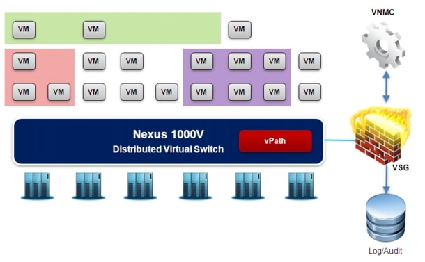
•![]() Virtual Network Management Center (VNMC) Server: VNMC is a virtual appliance that provides the centralized management point for managing the Virtual Security Gateway. This is also the central point of management for policies or creating security profile. VNMC is designed also to support multi-tenancy, it provides role-based access control and leverages the modern principles of a management architecture that is designed for virtualized and cloud environments.
Virtual Network Management Center (VNMC) Server: VNMC is a virtual appliance that provides the centralized management point for managing the Virtual Security Gateway. This is also the central point of management for policies or creating security profile. VNMC is designed also to support multi-tenancy, it provides role-based access control and leverages the modern principles of a management architecture that is designed for virtualized and cloud environments.
•![]() Virtual Security Gateway (VSG): VSG represents the policy node used to enforce security policies. VSG operates with the Cisco Nexus 1000V Series distributed virtual switch in VMware vSphere hypervisor, and it uses the vPath embedded in the Nexus 1000V Series VEM.
Virtual Security Gateway (VSG): VSG represents the policy node used to enforce security policies. VSG operates with the Cisco Nexus 1000V Series distributed virtual switch in VMware vSphere hypervisor, and it uses the vPath embedded in the Nexus 1000V Series VEM.
•![]() Nexus 1000V Virtual Switch: as previously discussed, Nexus 1000V represents Cisco implementation of a distributed and intelligent software switch for VMware vSphere environments, running the Cisco NX-OS Software operating system. To support the Cisco VSG solution, the Nexus 1000V must be running version 1.4 or later.
Nexus 1000V Virtual Switch: as previously discussed, Nexus 1000V represents Cisco implementation of a distributed and intelligent software switch for VMware vSphere environments, running the Cisco NX-OS Software operating system. To support the Cisco VSG solution, the Nexus 1000V must be running version 1.4 or later.
•![]() VMware vCenter: VMware vCenter Server manages the vSphere environment and provides unified management of all the hosts and VMs in the data center from a single console. You will need vCenter 4.0 and 4.1 with the Enterprise Plus license.
VMware vCenter: VMware vCenter Server manages the vSphere environment and provides unified management of all the hosts and VMs in the data center from a single console. You will need vCenter 4.0 and 4.1 with the Enterprise Plus license.
As mentioned, a VSG deployment leverages the Nexus 1000V virtual switch and the vPath technology. vPath represents the key functionality to enable virtual services in cloud environments, enabling traffic interception and redirection from each distributed VEM to the VSG security nodes. At the same time, vPath provides the ability to offload certain processing, for example firewall enforcement, inside the hypervisor itself. This mechanism provides significant performance benefits because the packets are anyway coming through the VEMs of the distributed N1KV switch, so vPath simply adds an additional step to the forwarding logic to provide enforcement of services policies.
A key benefit of the solution is that it also provides the ability to decouple the firewall services, from the compute workloads. Of course, VSGs can be placed on a VEM host where the VMs are deployed, but it can also be positioned or decoupled from the compute infrastructure and placed in a separate set of pool of servers or potentially implemented on appliances like the Nexus 1010. And so one can do capacity planning that is decoupled across application workloads and across network services.
 |
Note |
The procedure that allows providing intelligent traffic steering and policies enforcement with vPath is highlighted in Figure 2-25.
Figure 2-25 Security Policy Application with vPath
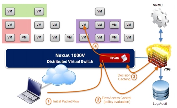
1. ![]() An initial packet (part of a specific flow) is originated from a client and destined to a VM connected to a Nexus 1000V VEM and deployed in a protected zone.
An initial packet (part of a specific flow) is originated from a client and destined to a VM connected to a Nexus 1000V VEM and deployed in a protected zone.
2. ![]() The port-profile associated to the vEth interfaces connecting to the VM has a security policies attached. As a consequence, vPath intercepts the traffic flow since it recognizes that any packet destined to that protected zone needs to be subject to a specific security policy defined within an appropriate VSG. vPath encapsulates the original packet with an outer L2 header and sends it to the MAC address of the VSG, representing the policy decision point.
The port-profile associated to the vEth interfaces connecting to the VM has a security policies attached. As a consequence, vPath intercepts the traffic flow since it recognizes that any packet destined to that protected zone needs to be subject to a specific security policy defined within an appropriate VSG. vPath encapsulates the original packet with an outer L2 header and sends it to the MAC address of the VSG, representing the policy decision point.
 |
Note |
1. ![]() The specific security policy is applied on the VSG policy node; the VSG stores the decision in its own flow cache (named the "master flow table") and then sends the decision back to vPath on the specific VEM where the VM is located. vPath caches the same policy decision in its own local cache. It is worth noticing that since the vPath functionality is distributed to each VEM server, the local cache information is not the same across different vPath in different servers. The population of the local cache is purely traffic driven, thus it is populated with policy decisions that are relevant only to a specific local host.
The specific security policy is applied on the VSG policy node; the VSG stores the decision in its own flow cache (named the "master flow table") and then sends the decision back to vPath on the specific VEM where the VM is located. vPath caches the same policy decision in its own local cache. It is worth noticing that since the vPath functionality is distributed to each VEM server, the local cache information is not the same across different vPath in different servers. The population of the local cache is purely traffic driven, thus it is populated with policy decisions that are relevant only to a specific local host.
2. ![]() If the policy decision is a "permit", the packet is then forwarded to the destination VM in the protected zone. Now, since vPath has the policy decision associated to that specific flow stored in its local cache, it is able to apply that decision to subsequent packets in the hypervisor kernel and, hence, able to provide firewall enforcement to all the packets right in the data path. This is the fast path available in software in the hypervisor that provides significant performance improvement, because packets no longer have to go through the policy decision point.
If the policy decision is a "permit", the packet is then forwarded to the destination VM in the protected zone. Now, since vPath has the policy decision associated to that specific flow stored in its local cache, it is able to apply that decision to subsequent packets in the hypervisor kernel and, hence, able to provide firewall enforcement to all the packets right in the data path. This is the fast path available in software in the hypervisor that provides significant performance improvement, because packets no longer have to go through the policy decision point.
Notice that the firewall functionalities provided by the VSG policy node and described above are enabled on a port-profile level. This means for example that in a multi-tenancy scenario, the same VEM can hosts virtual machines belonging to different tenants and a separate VSG per tenant is then used to provide security policies enforcement (a dedicate active/standby VSG pair per tenant is the only supported deployment model at the time of writing of this document).
 |
Note |
Stretched VSG Model
All the security policies defined on the VSG centralized policy node are applied to zones, which represent a logical construct. Zones are very flexible: they can be associated to a VLAN for example, or they can be defined within a VLAN, in order to segregate traffic between VMs belonging to that VLAN.
Most importantly for the purpose of supporting virtualized workload mobility, zones are very flexible by nature: as VMs moves between VEMs, the zones extend or shrink in order to ensure that the security policies are appropriately applied and security policies remain valid transparently to the mobility events.
The deployment of VSG can then be coupled with the stretched Nexus 1000V deployment discussed in the previous section. Figure 2-26 highlights the scenario where the N1KV virtual switch is deployed inside an ESX cluster that stretches between two data center sites.
Figure 2-26 Stretched VSG Deployment
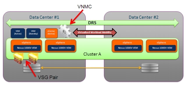
Some of the characteristics of this specific solution are discussed below:
•![]() VSG deployment: similarly to how discussed for the VSMs, both active and standby VSGs should currently be positioned in the same Data Center site. This is the only recommended and supported option at the time of writing of this document to avoid the possibility of a "split-brain" scenario, where both VSGs are activated in different sites as a consequence of a complete failure of the DCI connection between sites.
VSG deployment: similarly to how discussed for the VSMs, both active and standby VSGs should currently be positioned in the same Data Center site. This is the only recommended and supported option at the time of writing of this document to avoid the possibility of a "split-brain" scenario, where both VSGs are activated in different sites as a consequence of a complete failure of the DCI connection between sites.
•![]() As mentioned, both active and standby VSGs can be deployed as Virtual Machines belonging to a specific ESX host. It is recommended to deploy each VSG in an active-standby pair on a separate VMware ESX host. This requirement helps ensure high availability even if one of the VMware ESX servers fails. You can also use the anti-affinity option in VMware ESX to help keep the VSGs on different servers. Currently, there is no support for VSG with the Nexus 1010 appliance.
As mentioned, both active and standby VSGs can be deployed as Virtual Machines belonging to a specific ESX host. It is recommended to deploy each VSG in an active-standby pair on a separate VMware ESX host. This requirement helps ensure high availability even if one of the VMware ESX servers fails. You can also use the anti-affinity option in VMware ESX to help keep the VSGs on different servers. Currently, there is no support for VSG with the Nexus 1010 appliance.
•![]() The VSG Virtual Machines, similarly to what discussed for the VSM ones, are connected to the same VEM hosting the virtual machines to which security policies are applied. No specific design consideration or use of special "System VLANs" are required in this case.
The VSG Virtual Machines, similarly to what discussed for the VSM ones, are connected to the same VEM hosting the virtual machines to which security policies are applied. No specific design consideration or use of special "System VLANs" are required in this case.
•![]() Security policies migration: as mentioned, the VSG behavior has been designed so to ensure that the application of the security policies remain valid independently from the mobility events. Let's analyze step-by-step what is the process for security policy application before and after workload migration:
Security policies migration: as mentioned, the VSG behavior has been designed so to ensure that the application of the security policies remain valid independently from the mobility events. Let's analyze step-by-step what is the process for security policy application before and after workload migration:
1. ![]() Let's assume that a given security policy is applied to a traffic flow to/from a VM deployed on a local VEM in DC1. This is the steady state at the end of the process described in Security Policy Application with vPath32. The policy decision for that flow is stored both on the VSG (in the "master flow table") and on the vPath (in the local cache).
Let's assume that a given security policy is applied to a traffic flow to/from a VM deployed on a local VEM in DC1. This is the steady state at the end of the process described in Security Policy Application with vPath32. The policy decision for that flow is stored both on the VSG (in the "master flow table") and on the vPath (in the local cache).
2. ![]() The VM is migrated from the VEM in DC1 to a VEM in DC2. As already pointed out, the content of the vPath local cache is specific to each VEM, so the new VEM in DC2 has no policy information for that specific flow. As a consequence, vPath intercepts the first packet as soon the VM is enabled (after migration is completed).
The VM is migrated from the VEM in DC1 to a VEM in DC2. As already pointed out, the content of the vPath local cache is specific to each VEM, so the new VEM in DC2 has no policy information for that specific flow. As a consequence, vPath intercepts the first packet as soon the VM is enabled (after migration is completed).
3. ![]() vPath encapsulates the packet and sends it to the active VSG node. Since this needs to happen at L2 and the VSG is located in DC1, the VLAN used for the VSG-VEM communication must be extended between sites across the DCI connection.
vPath encapsulates the packet and sends it to the active VSG node. Since this needs to happen at L2 and the VSG is located in DC1, the VLAN used for the VSG-VEM communication must be extended between sites across the DCI connection.
4. ![]() The VSG receives the packet and finds in its "master flow cache" all the information (the "state") for that specific flow. The VSG communicate the policy decision and the state information to the VEM, which stores them in its local cache. The traffic flows can be now successfully re-established and the security policies applied in the data path.
The VSG receives the packet and finds in its "master flow cache" all the information (the "state") for that specific flow. The VSG communicate the policy decision and the state information to the VEM, which stores them in its local cache. The traffic flows can be now successfully re-established and the security policies applied in the data path.
It is important to highlight that vPath tracks Layer 4 information for all the traffic flows (sequence numbers, TCP flags, etc.). This is the type of information referred to as "state" in step 4 above. However, there are some stateful applications that require dynamic opening of additional TCP/UDP sessions as part of the application communication. Support for application level protocol fixup is required to dynamically allow additional connections by doing packet inspection. In the first release of VSG, this capability is limited to FTP, RSH and TFTP, with a plan to add more in future releases.
Using FTP as an example, what stated above means that if a given client is performing an FTP operation (read or write) to an FTP server running on a virtual machine (in a zone protected by a specific security policy), the FTP operation continues also once the VM is migrated to a VEM residing in a remote data center site. This is the demonstration that the security policy effectively moves together with the virtual machine, which represents a critical functionality in a virtualized workload mobility solution.
 |
Note |
•![]() DCI connection failure: the deployment of VSG in conjunction with a Nexus 1000V switch stretched between data center sites raises some questions on the system behavior under the specific circumstances of DCI connection outage, which leads to isolating the two physical locations. As mentioned, the first recommendation is to deploy both the active and standby VSGs in the same site, to avoid split-brain scenarios. However, it is important also to consider the interactions between the other functional components, as for example:
DCI connection failure: the deployment of VSG in conjunction with a Nexus 1000V switch stretched between data center sites raises some questions on the system behavior under the specific circumstances of DCI connection outage, which leads to isolating the two physical locations. As mentioned, the first recommendation is to deploy both the active and standby VSGs in the same site, to avoid split-brain scenarios. However, it is important also to consider the interactions between the other functional components, as for example:
–![]() VNMC-vCenter communication: VNMC registers with vCenter to have visibility into the VMware environment. This allows the security administrator to define security policies based on specific VMware VM attributes. Both VNMC and vCenter should usually be deployed as part of the same site (as shown in Stretched VSG Deployment33), so their communication is most of the time unaffected by failures in the DCI connection. If for some reason there was an outage in the DCI connection when VNMC and vCenter are deployed in separate sites (maybe because the outage happened in the middle of a migration procedure), there would be two main effects: first, new VMs coming up in vCenter will not be learnt by VSG and therefore any rules/policies using VM attributes will not work for these new VMs. Second, any change in the properties of a given VM will not by learnt by VNMC so will not be effective for rules/policies. It is worth noticing that existing VMs/data sessions will keep working and any rule using network 5-tuple (i.e. not using VM attributes) will work even for new VMs.
VNMC-vCenter communication: VNMC registers with vCenter to have visibility into the VMware environment. This allows the security administrator to define security policies based on specific VMware VM attributes. Both VNMC and vCenter should usually be deployed as part of the same site (as shown in Stretched VSG Deployment33), so their communication is most of the time unaffected by failures in the DCI connection. If for some reason there was an outage in the DCI connection when VNMC and vCenter are deployed in separate sites (maybe because the outage happened in the middle of a migration procedure), there would be two main effects: first, new VMs coming up in vCenter will not be learnt by VSG and therefore any rules/policies using VM attributes will not work for these new VMs. Second, any change in the properties of a given VM will not by learnt by VNMC so will not be effective for rules/policies. It is worth noticing that existing VMs/data sessions will keep working and any rule using network 5-tuple (i.e. not using VM attributes) will work even for new VMs.
 |
Note |
–![]() VNMC-VSG communication: VSG registers with VNMC (via an SSL connection), and this allows the VNMC to push the defined security policies to it. Since no policy configuration can be done via VSG CLI after this registers with VNMC, it is clear that new policies or policy modifications cannot be applied if the VSG and the VNMC should become isolated from each other.
VNMC-VSG communication: VSG registers with VNMC (via an SSL connection), and this allows the VNMC to push the defined security policies to it. Since no policy configuration can be done via VSG CLI after this registers with VNMC, it is clear that new policies or policy modifications cannot be applied if the VSG and the VNMC should become isolated from each other.
–![]() VSG-VEM (vPath) communication: this VSG-VEM interaction is critical to ensure that the security policies can be applied when new flows are intercepted by the vPath functionality in the VEM. Since the active/standby VSGs would most likely be deployed in a single site, it is expected that the failure of the DCI connection would cause the impossibility for vPath to forward to the active VSG the first packet of new flows established to/from VMs belonging to the VEMs in the remote site. Under these circumstances, it is possible to configure what should be the policy enforcement behavior: if the "fail open" option is selected, new flows to/from these VMs will be allowed bypassing the security policy. If the "fail close" option is chosen, then new flows will not be allowed and communication to/from the VMs will be prevented. Existing flows will continue to flow without interruption, independently from the chosen mode of operation.
VSG-VEM (vPath) communication: this VSG-VEM interaction is critical to ensure that the security policies can be applied when new flows are intercepted by the vPath functionality in the VEM. Since the active/standby VSGs would most likely be deployed in a single site, it is expected that the failure of the DCI connection would cause the impossibility for vPath to forward to the active VSG the first packet of new flows established to/from VMs belonging to the VEMs in the remote site. Under these circumstances, it is possible to configure what should be the policy enforcement behavior: if the "fail open" option is selected, new flows to/from these VMs will be allowed bypassing the security policy. If the "fail close" option is chosen, then new flows will not be allowed and communication to/from the VMs will be prevented. Existing flows will continue to flow without interruption, independently from the chosen mode of operation.
 |
Note |
•![]() Migration procedure for VSGs: in some specific scenarios (maintenance, disaster avoidance procedures, etc.) it may be required to migrate a VSG virtual machine between ESX hosts. The same considerations previously made for VSM migration remain valid, and the migration procedure is pretty much identical:
Migration procedure for VSGs: in some specific scenarios (maintenance, disaster avoidance procedures, etc.) it may be required to migrate a VSG virtual machine between ESX hosts. The same considerations previously made for VSM migration remain valid, and the migration procedure is pretty much identical:
1. ![]() For the duration the following events take place, do not bring up any new VMs or vMotion other VMs.
For the duration the following events take place, do not bring up any new VMs or vMotion other VMs.
2. ![]() Power off the standby VSG and migrate it from the first site to the second site.
Power off the standby VSG and migrate it from the first site to the second site.
3. ![]() Perform a storage vMotion for the standby VSG storage (if storage vMotion is needed).
Perform a storage vMotion for the standby VSG storage (if storage vMotion is needed).
4. ![]() Migrate the original active VSG from the first site to the second site.
Migrate the original active VSG from the first site to the second site.
5. ![]() Perform a storage vMotion for the original active VSG storage (if storage vMotion is needed).
Perform a storage vMotion for the original active VSG storage (if storage vMotion is needed).
6. ![]() Power on the standby VSG and reform an HA-pair.
Power on the standby VSG and reform an HA-pair.
 |
Note |
Similarly to what mentioned for the VSM migration procedure, the VLAN where the active/standby VSGs are deployed needs to be extended between data center sites to allow a successful completion of the vMotion process. Given the fact that the communication between the active VSG and the distributed VEMs is currently only happening at L2, it is expected that such VLAN would be already extended to allow the remote VEMs to communicate back to the VSG.
Storage Elasticity
One of the most underrated components of a holistic DCI solution is the storage deployment. This becomes specifically relevant in the workload mobility scenario, where in order to be able to move VMs across data center sites, it is critical to ensure a consistent access to the storage for the ESX hosts where the VMs reside.
The following sections will clarify what are the specific storage requirements for ESX hosts in order to enable workload mobility between data center locations, and will discuss a couple of specific Intelligent Storage solutions.
ESX Host Storage Requirements for Virtualized Workload Mobility
Virtual Machines use virtual disks for storage. The virtual disk is actually not a disk but a VM disk image file (VMDK). This file exists with the VM file system (VMFS), which is a flat file system created for better performance. Therefore, the guest operating system and its associated applications are installed into a .VMDK file residing in a VMFS on the physical storage. The physical storage may generically be a local hard drive on the ESX host system or a remote storage device located in the SAN.
However, one of the basic requirements for vMotion support is that the source and destination ESX host can access the same physical storage, in order to be able to expose the same virtual disk to the VM before and after vMotion is completed (as previously highlighted in Figure 2-21). As a consequence, typically the disk image (VMDK) file is stored in an external disk array and the ESX source and target servers simply swap control of the file lock after the VM state information synchronizes.
 |
Note |
In the context of this paper, two different types of storage deployments have been validated and considered:
1. ![]() Shared storage: all the ESX hosts are exposed to the same physical storage that is deployed in a specific data center location, so storage extension capabilities are leveraged to provide access to it from ESX host available in different sites.
Shared storage: all the ESX hosts are exposed to the same physical storage that is deployed in a specific data center location, so storage extension capabilities are leveraged to provide access to it from ESX host available in different sites.
2. ![]() Active/active storage: all the ESX hosts are this time exposed to a common virtual storage entity. The storage access is virtualized by deploying EMC VPLEX Metro, which allows local access to the physical storage disk available on the local SAN and synchronization of information between physical storage resources deployed in separate sites.
Active/active storage: all the ESX hosts are this time exposed to a common virtual storage entity. The storage access is virtualized by deploying EMC VPLEX Metro, which allows local access to the physical storage disk available on the local SAN and synchronization of information between physical storage resources deployed in separate sites.
The following sections will provide more details on each of these specific storage options.
Shared Storage Model
The shared storage model is conceptually the simplest: all the ESX hosts deployed in both data center sites have access to the same disk array, which is physically available in a specific location. When deploying this approach in the context of a virtualized workload mobility solution, some restrictions in terms of distance and latency between sites become suddenly apparent, considering that hosts located in remote sites will have to perform all their I/O operations (read and write) to the centralized disk array. This model may be deployable in scenarios where workload mobility is deployed between sites in close proximity to each other (few kilometers) like it would be the case for example when the data centers are connected to a common Campus network.
Multiple protocols (Fibre Channel, NFS, iSCSI, etc.) may be used to provide disk access to the hosts. In the following sections the FC option is discussed more in detail.
FC Access to Shared Storage
The validated storage model leverages an EMC FC disk array (DMX3 model) deployed in data center DC1. ESX hosts deployed in DC1 have local access to the disk array through the local SAN. ESX hosts deployed in DC2 leverage the SAN extension capabilities of Cisco MDS devices to be able to access the centralized disk array. As highlighted in Figure 2-27, FC connectivity is extended directly over a dedicated DWDM connection.
Figure 2-27 FC Access to Shared Storage
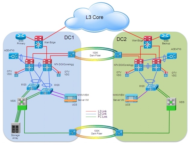
Some of the design considerations around this model are the following:
•![]() VSAN definition: a separate VSAN is defined in each DC site. The ESX hosts and the storage array in DC1 are part of VSAN A, whereas the ESX hosts in DC2 are part of VSAN B. Inter-VSAN Routing (IVR) is configured to allow VSAN A to VSAN B communication across the DWDM FC connection.
VSAN definition: a separate VSAN is defined in each DC site. The ESX hosts and the storage array in DC1 are part of VSAN A, whereas the ESX hosts in DC2 are part of VSAN B. Inter-VSAN Routing (IVR) is configured to allow VSAN A to VSAN B communication across the DWDM FC connection.
•![]() Zoning is configured to restrict access to the disk array only from the ESX hosts in DC1 and DC2.
Zoning is configured to restrict access to the disk array only from the ESX hosts in DC1 and DC2.
•![]() 802.1AE is enabled on the MDS interfaces connecting to the DWDM ring to provide encryption services for all the SAN extension traffic. This could be for example driven by specific compliance requirements and does not have any impact on traffic throughput, since the MDS performs 802.1AE encryption at wire speed in the port ASICs.
802.1AE is enabled on the MDS interfaces connecting to the DWDM ring to provide encryption services for all the SAN extension traffic. This could be for example driven by specific compliance requirements and does not have any impact on traffic throughput, since the MDS performs 802.1AE encryption at wire speed in the port ASICs.
•![]() Virtualized workload mobility implications: when migrating a workload from DC1 to DC2, it is important to consider the impact on the applications running on the virtual machine, given the increased distance from the disk array.
Virtualized workload mobility implications: when migrating a workload from DC1 to DC2, it is important to consider the impact on the applications running on the virtual machine, given the increased distance from the disk array.
•![]() In order to address disk array or site failure scenarios, it is usually recommend to perform storage replication to a remote disk array located in the same DC2 site used to perform workload mobility or in a dedicated disaster recovery facility. Disaster recovery design considerations are out of the scope of this paper.
In order to address disk array or site failure scenarios, it is usually recommend to perform storage replication to a remote disk array located in the same DC2 site used to perform workload mobility or in a dedicated disaster recovery facility. Disaster recovery design considerations are out of the scope of this paper.
Active/Active Model: EMC VPLEX Metro
A further improvement to the Active/Cache functionality discussed in the previous section is provided by an Active/Active approach, which integrates caching functionality with the actual capability of distributing disk arrays in separate locations. The solution validated in the context of this paper is called VPLEX Metro and provided by EMC.
EMC VPLEX Metro Functional Overview
The VPLEX family uses a unique clustering architecture which breaks the boundaries of a data center and allows servers at multiple data centers to have read/write access to shared block storage devices. As shown in Figure 2-28, two VPLEX clusters deployed in separate sites can be connected together to form a VPLEX Metro solution.
Figure 2-28 VPLEX Metro Solution
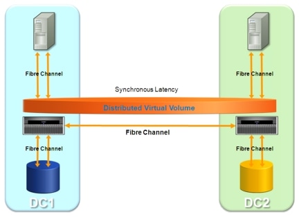
VPLEX Metro supports up to two clusters (in the validated 4.2 release), which can be in the same data center, or at two different sites with synchronous distances (approximately up to 100 kilometers apart).
In the context of virtualized workload mobility, VPLEX Metro provides mobility and relocation between locations over synchronous distances. In combination with VMware and vMotion over distance, VPLEX Metro allows users to transparently move and relocate virtual machines and their corresponding applications and data over distance. This provides a unique capability allowing users to relocate, share and balance infrastructure resources between data centers.
Each VPLEX cluster can contain one, two or four VPLEX engines. The VPLEX engine is responsible for the virtualization of the I/O stream. Each engine contains two directors, equipped with memory, Solid State Drive (SSD) memory and Fibre Channel interfaces to connect to the host (front-end) and to the storage array (back-end). Each director contains also a module with Fibre Channel interfaces used to connect to other directors and VPLEX engines.
 |
Note |
From a Fibre Channel point of view, a VPLEX engine behaves at the same time as a target (for host I/O operations) and as an initiator (for disk array I/O operations), as highlighted in Figure 2-29.
Figure 2-29 Initiator and Target Roles with VPLEX

It is important to highlight how there are really no dependencies between the VPLEX Engine and the specific disk array deployed on the SAN, which means VPLEX can support a variety of arrays from various vendors. VPLEX simplifies storage management by allowing simple LUNs, provisioned from the various arrays, to be managed through a centralized management interface. In addition, a VPLEX Metro environment that spans data centers allows the storage administrator to manage both locations through a single interface from either location by logging in at the local site.
In order to better understand how a VPLEX cluster handles I/O operations (read and write), it is important to clarify the VPLEX cluster caching layers, roles and interactions. More specifically, a local cache is available on each director, whereas a global cache includes all directors that are connected to one another within the same VPLEX cluster (remember that there are two directors per VPLEX engine).
VPLEX Read Operations
The sequence of events required when a host performs a read operation is displayed in Figure 2-30.
Figure 2-30 Read Operation

•![]() When a host makes a read request, VPLEX first searches the data into the local cache of the director that directly received the request (step 1).
When a host makes a read request, VPLEX first searches the data into the local cache of the director that directly received the request (step 1).
•![]() If the data is found there, it is returned to the host right away. If the data is not found in the local cache, VPLEX searches the global cache (step 2). When the data is found and serviced from the global cache, a copy is also stored in the local cache of the director from where the request originated.
If the data is found there, it is returned to the host right away. If the data is not found in the local cache, VPLEX searches the global cache (step 2). When the data is found and serviced from the global cache, a copy is also stored in the local cache of the director from where the request originated.
•![]() If a read cannot be serviced from either local cache or global cache, it is read directly from the back-end storage (step 3). In this case both the global and local caches are updated to maintain cache coherency.
If a read cannot be serviced from either local cache or global cache, it is read directly from the back-end storage (step 3). In this case both the global and local caches are updated to maintain cache coherency.
VPLEX Write Operations
Differently from what happens for read operations, all writes are written through the cache to the back-end storage. Writes are completed to the host only after they have been completed to the back-end arrays. As it will be clarified better in the following section, it is this mechanism that limits the extension of the VPLEX Metro solution to only 100 Kilometers.
Figure 2-31 highlights the sequence of events required for a VPLEX write operation.
Figure 2-31 Write Operation

•![]() When a write request is issued from a host to a virtual volume, prior data are first searched in the local cache and, if found, they are invalidated (step 1).
When a write request is issued from a host to a virtual volume, prior data are first searched in the local cache and, if found, they are invalidated (step 1).
•![]() Prior data are then searched in the global cache, and if found they are invalidated (step 2).
Prior data are then searched in the global cache, and if found they are invalidated (step 2).
•![]() New written data are written to the local cache (step 3).
New written data are written to the local cache (step 3).
•![]() Data is written to the back-end storage array (step 4).
Data is written to the back-end storage array (step 4).
•![]() Write operation is acknowledged to the original host (step 5).
Write operation is acknowledged to the original host (step 5).
Use of EMC VPLEX Metro to Enable Virtualized Workload Mobility
EMC VPLEX with the EMC GeoSynchrony operating system breaks physical barriers of data centers and allows users to access data for read and write operations at different geographical locations concurrently. This is achieved by synchronously replicating data between the data centers while depending on the hosts accessing the storage devices to manage the consistency through the use of intelligent distributed lock management. This capability in a VMware context enables functionalities that were not available earlier. Specifically, the ability to concurrently access the same set of devices independent of the physical location enables geographical vMotion based on the VMware virtualization platform. This allows for transparent load sharing between multiple sites while providing the flexibility of migrating workloads between sites in anticipation of planned events, such as hardware maintenance. Furthermore, in case of an unplanned event that causes disruption of services at one of the data centers, the failed services can be quickly and easily restarted at the surviving site with minimal effort.
EMC VPLEX Metro Deployment39 provides an overall view of the topology where two EMC VPLEX clusters were integrated as part of the VPLEX Metro solution to provide added value to a virtualized workload mobility solution.
Figure 2-32 EMC VPLEX Metro Deployment
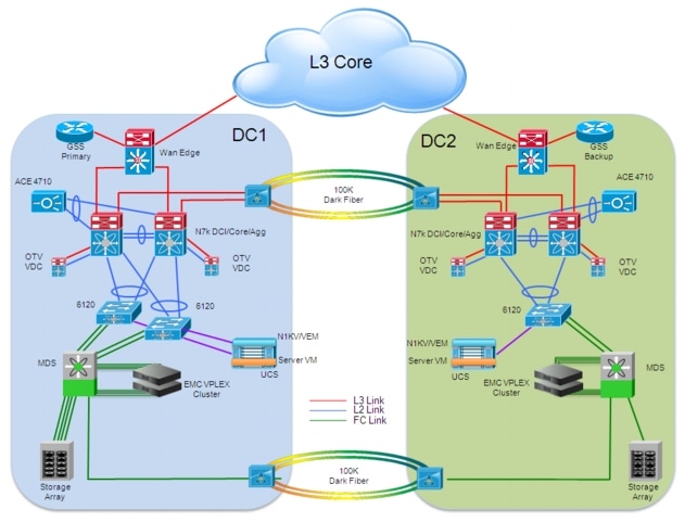
•![]() A VPLEX Metro cluster is deployed in each data center site with two engines in each cluster. The front-end and back-end Fibre Channel interfaces of the directors in the cluster are connecting to the SAN (implemented with an MDS switch), providing connectivity to the ESX hosts and the back-end storage array. As previously shown in Initiator and Target Roles with VPLEX36, each VPLEX Engine acts at the same time as a FC target for I/O operations initiated by hosts and as an I/O initiator toward FC target disk arrays on the SAN. The front-end ports on all directors provide active/active access to the virtual volumes exported by the cluster. For maximum availability, virtual volumes must be presented through each director so that all directors but one can fail without causing data loss or unavailability. As shown in the figure above, multiple front-end and back-end links are deployed to connect the 4 directors available in each cluster to the SAN. When following the best practice of building a pair of redundant Fibre Channel fabrics (SAN A/SAN B), the directors would be connected to both SAN fabrics, both for the front-end and back-end connectivity.`
A VPLEX Metro cluster is deployed in each data center site with two engines in each cluster. The front-end and back-end Fibre Channel interfaces of the directors in the cluster are connecting to the SAN (implemented with an MDS switch), providing connectivity to the ESX hosts and the back-end storage array. As previously shown in Initiator and Target Roles with VPLEX36, each VPLEX Engine acts at the same time as a FC target for I/O operations initiated by hosts and as an I/O initiator toward FC target disk arrays on the SAN. The front-end ports on all directors provide active/active access to the virtual volumes exported by the cluster. For maximum availability, virtual volumes must be presented through each director so that all directors but one can fail without causing data loss or unavailability. As shown in the figure above, multiple front-end and back-end links are deployed to connect the 4 directors available in each cluster to the SAN. When following the best practice of building a pair of redundant Fibre Channel fabrics (SAN A/SAN B), the directors would be connected to both SAN fabrics, both for the front-end and back-end connectivity.`
 |
Note |
•![]() The two local VPLEX cluster are federated, leveraging the Fibre Channel connection established between sites across dedicated FC links. Each local cluster controls its own local storage array. Devices provided from both clusters can be combined to form distributed devices, which become a single entity across the clusters ad appear on each side as though it were a single device. Storage federation provides a layer between the server and the storage that enables movement of data between the underlying storage systems, completely transparent to the host environment.
The two local VPLEX cluster are federated, leveraging the Fibre Channel connection established between sites across dedicated FC links. Each local cluster controls its own local storage array. Devices provided from both clusters can be combined to form distributed devices, which become a single entity across the clusters ad appear on each side as though it were a single device. Storage federation provides a layer between the server and the storage that enables movement of data between the underlying storage systems, completely transparent to the host environment.
•![]() VSANs, zoning and Inter VSAN Routing (IVR) functionalities can be leveraged in this deployment given the availability of Cisco MDS fabric switches. More specifically: the ESX hosts (on UCS system) and the VPLEX front-end cluster interfaces are part of the same VSAN (for example VSAN 100 in DC1 and VSAN 200 in DC2) and zoning is configured to allow only specific hosts to access the virtual disk exposed by VPLEX. The VPLEX back-end interfaces and the target disk array are also part of the same VSAN (in the example above, VSAN 100 in DC1 and 202 in DC2) and again zoning is leveraged to restrict VPLEX to disk array communication. Connectivity between the VPLEX clusters is provided across the dark fiber links via a dedicated VSAN (for example VSAN 300) and using the IVR functionality.
VSANs, zoning and Inter VSAN Routing (IVR) functionalities can be leveraged in this deployment given the availability of Cisco MDS fabric switches. More specifically: the ESX hosts (on UCS system) and the VPLEX front-end cluster interfaces are part of the same VSAN (for example VSAN 100 in DC1 and VSAN 200 in DC2) and zoning is configured to allow only specific hosts to access the virtual disk exposed by VPLEX. The VPLEX back-end interfaces and the target disk array are also part of the same VSAN (in the example above, VSAN 100 in DC1 and 202 in DC2) and again zoning is leveraged to restrict VPLEX to disk array communication. Connectivity between the VPLEX clusters is provided across the dark fiber links via a dedicated VSAN (for example VSAN 300) and using the IVR functionality.
•![]() VPLEX provides a distributed block cache across all the directors, guaranteeing cache coherency across the entire solution. This lets applications access the data from any director in the cluster without having to worry about coherency. The GeoSynchrony operating system implementing this distributed cache keeps often-referenced data in the director that is accessing the data, optimizing access times.
VPLEX provides a distributed block cache across all the directors, guaranteeing cache coherency across the entire solution. This lets applications access the data from any director in the cluster without having to worry about coherency. The GeoSynchrony operating system implementing this distributed cache keeps often-referenced data in the director that is accessing the data, optimizing access times.
Each cluster in the VPLEX Metro solution provides storage for a distributed mirror whose virtual volume is available at both clusters for presentation to one or more initiators. From the point of view of I/O operations this means that:
–![]() If a host belonging to ESX servers located in the DC1 tries to read data from the virtual volume exposed to it, data is first searched in the caches (local or global) available in the VPLEX cluster deployed in DC1 (as already explained in the "VPLEX Read Operations" section). If the data is not available in the caches, then the VPLEX engine requests it from the local disk array. The same behavior is exhibited for read operations initiated by host deployed in ESX servers belonging to DC2. This essentially means that all the read operations are always localized and never require traversing the FC connection established between sites.
If a host belonging to ESX servers located in the DC1 tries to read data from the virtual volume exposed to it, data is first searched in the caches (local or global) available in the VPLEX cluster deployed in DC1 (as already explained in the "VPLEX Read Operations" section). If the data is not available in the caches, then the VPLEX engine requests it from the local disk array. The same behavior is exhibited for read operations initiated by host deployed in ESX servers belonging to DC2. This essentially means that all the read operations are always localized and never require traversing the FC connection established between sites.
–![]() If a host belonging to ESX servers located in the DC1 tries to write data to the virtual volume exposed to it, the write-through mode of operation of the VPLEX cluster implies that data must be written through the cache to all the back-end storage arrays, in order to maintain data integrity. This means that the writes are sent both to the local disk array in DC1 and the remote disk array deployed in the SAN in DC2.
If a host belonging to ESX servers located in the DC1 tries to write data to the virtual volume exposed to it, the write-through mode of operation of the VPLEX cluster implies that data must be written through the cache to all the back-end storage arrays, in order to maintain data integrity. This means that the writes are sent both to the local disk array in DC1 and the remote disk array deployed in the SAN in DC2.
The FC connection between sites is leveraged to allow the writes to be sent to the remote disk array (in both DC1‡DC2 and DC2‡DC1 directions). This is achieved through a specific FC initiator-target session established between the local and the remote VPLEX Engines. No acknowledgment can be sent to the host initiating the write operation until the data has been written to all the local and remote disk arrays. It is this synchronous behavior that limits the applicability of VPLEX Metro deployments to sites that are a distance of 100 kilometers or less.
•![]() Similarly to what discussed in the FC Shared Storage model, 802.1AE is enabled on the MDS interfaces connecting to the DWDM ring to provide encryption services for all the traffic carried across this connection.
Similarly to what discussed in the FC Shared Storage model, 802.1AE is enabled on the MDS interfaces connecting to the DWDM ring to provide encryption services for all the traffic carried across this connection.
•![]() Since the two VPLEX clusters are deployed in separate sites, it is important to consider what happens if Fibre Channel communication between the two sites is interrupted. Under these circumstances the two VPLEX clusters lose connectivity with each other and a configurable detach rule will let one of the two VPLEX clusters continue I/O while the virtual volumes on the other clusters remain suspended. After detaching a distributed device, local writes no longer go to the remote mirror leg but instead are committed to the local mirror leg only. The remote cluster, not having detached the distributed device, will keep I/O to that device suspended until communication with the other cluster is restored. It is also important to consider that the detach rule can be configured on a virtual volume level, which implies that it is possible to have active virtual volumes on both sites in case of a network partition.
Since the two VPLEX clusters are deployed in separate sites, it is important to consider what happens if Fibre Channel communication between the two sites is interrupted. Under these circumstances the two VPLEX clusters lose connectivity with each other and a configurable detach rule will let one of the two VPLEX clusters continue I/O while the virtual volumes on the other clusters remain suspended. After detaching a distributed device, local writes no longer go to the remote mirror leg but instead are committed to the local mirror leg only. The remote cluster, not having detached the distributed device, will keep I/O to that device suspended until communication with the other cluster is restored. It is also important to consider that the detach rule can be configured on a virtual volume level, which implies that it is possible to have active virtual volumes on both sites in case of a network partition.
If a site failure scenario caused the communication interruption between cluster peers, it may happen that the VPLEX cluster at the surviving site automatically suspends the I/O to some of the virtual volumes at the surviving site. To address this specific scenario, the VPLEX software provides the capability to manually resume I/Os to the detached devices.
 |
Note |
When communication between the two clusters is restored, VPLEX Metro will automatically re-sync both distributed mirror legs by updating the remote mirror legs with all the writes that occurred after the detach. The other cluster can now resume after having been suspended during the link outage.
•![]() The deployment of VPLEX Metro enables distributed data access but provides at the same time mirroring capabilities between disk arrays deployed in separate data center sites. VPLEX supports in fact the ability to mirror the data of a virtual volume between two or more storage volumes using a RAID 1 device. This is very relevant to ensure data preservation in site failure scenarios.
The deployment of VPLEX Metro enables distributed data access but provides at the same time mirroring capabilities between disk arrays deployed in separate data center sites. VPLEX supports in fact the ability to mirror the data of a virtual volume between two or more storage volumes using a RAID 1 device. This is very relevant to ensure data preservation in site failure scenarios.

 Feedback