Cisco Smart+Connected Meeting Spaces & Cisco Smart+Connected Digital Signage Installation Guide
Bias-Free Language
The documentation set for this product strives to use bias-free language. For the purposes of this documentation set, bias-free is defined as language that does not imply discrimination based on age, disability, gender, racial identity, ethnic identity, sexual orientation, socioeconomic status, and intersectionality. Exceptions may be present in the documentation due to language that is hardcoded in the user interfaces of the product software, language used based on RFP documentation, or language that is used by a referenced third-party product. Learn more about how Cisco is using Inclusive Language.
- Updated:
- May 15, 2013
Chapter: Getting Started
Getting Started
This chapter provides information on the architecture, prerequisites, and deployment models of the Cisco Smart+Connected Meeting Spaces & Cisco Smart+Connected Digital Signage (Smart+Connected MS & DS) application.
•![]() List of Acronyms and Abbreviations
List of Acronyms and Abbreviations
Overview
The Smart+Connected MS & DS application allows you to easily access information by using digital signages, IP phones, and the web portal. For example, you can easily view information, such as meeting details, news, energy consumption data, energy saving tips, and so on. The application also allows you to book meetings instantly using touchscreen digital signage and IP phones, manage conference room resources, and report the issues, if any, in the conference rooms. The automatic energy saving settings lead to reduced power consumption and contribute to the eco-friendly policies of the organization. In case of any mishaps, emergency notifications are sent out to the users through IP phone and digital signage.
The Cisco Smart+Connected MS is a solution that leverages the Cisco Service Delivery Platform (SDP). It provides features for conference room management and signage-based messaging using Cisco IP phones. The Smart+Connected MS leads to enhanced enterprise communication as the updated meeting room information is widely available and easily accessible to employees. It also leads to better resource management and energy savings which translate to reduced energy bills and more environment-friendly corporate practices.
The Smart+Connected MS solution allows the end user to do the following:
•![]() Using Digital Signage
Using Digital Signage
–![]() Book meeting spaces and TelePresence rooms
Book meeting spaces and TelePresence rooms
–![]() Book conference rooms.
Book conference rooms.
–![]() View detailed floor plans with locations of conference rooms.
View detailed floor plans with locations of conference rooms.
–![]() View news content associated with the location.
View news content associated with the location.
•![]() Using Web Portal and IP Phones
Using Web Portal and IP Phones
–![]() Book conference rooms.
Book conference rooms.
–![]() Manage meeting room devices and equipment.
Manage meeting room devices and equipment.
–![]() Configure multiple devices to suit your meeting and presentation needs using a single menu selection.
Configure multiple devices to suit your meeting and presentation needs using a single menu selection.
–![]() Create a case to resolve a fault in a conference room, and convey the same to the others in the organization by sending messages to the digital signage.
Create a case to resolve a fault in a conference room, and convey the same to the others in the organization by sending messages to the digital signage.
In addition, the solution can help in energy savings by automatically switching devices to a standby mode when the meeting room is unoccupied and based on the configuration, turn them back on before the actual occupancy.
As an administrator, you have to manage the overall configuration, maintenance, and content creation for the Smart+Connected MS solution through a web portal. You have to add locations and devices, create users, and associate devices to locations for the solution in the SDP. For more information on performing these tasks, see the Cisco Service Delivery Platform User Guide and Cisco Service Delivery Platform Installation Guide. After the locations are added, and the devices are associated to them in the SDP, they are available in the Smart+Connected MS portal. You can select a location and associate a configuration to it. The features such as fault messages, device control options, signage menu messaging, and room booking that are added to the configuration can be accessed by the end user from the Cisco IP phones at the location.
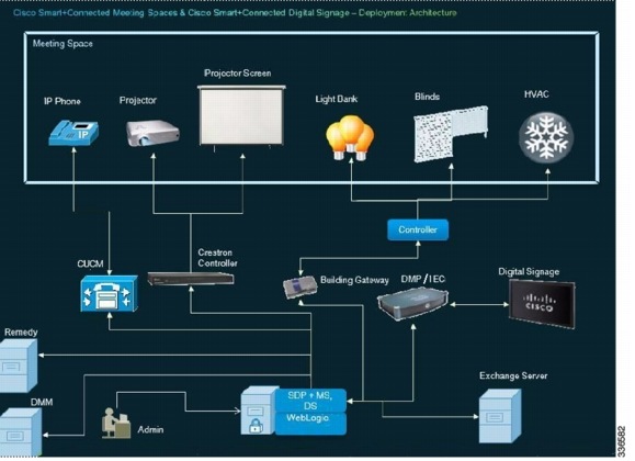
System Architecture
The Smart+Connected MS & DS application communicates with the following:
•![]() Microsoft Exchange—To book meetings and retrieve meeting details.
Microsoft Exchange—To book meetings and retrieve meeting details.
•![]() Building Management System (BMS)—To control and monitor devices, such as lights, blinds, and air conditioners.
Building Management System (BMS)—To control and monitor devices, such as lights, blinds, and air conditioners.
•![]() Content Management System (CMS)—To store the application data.
Content Management System (CMS)—To store the application data.
•![]() Crestron Controller—To control projectors and projector screens.
Crestron Controller—To control projectors and projector screens.
•![]() Digital Media Player (DMP) and Cisco Interactive Experience Client (IEC)—To display meeting details, notifications, general information, news, energy consumption data, energy saving tips, and so on, on the digital signages.
Digital Media Player (DMP) and Cisco Interactive Experience Client (IEC)—To display meeting details, notifications, general information, news, energy consumption data, energy saving tips, and so on, on the digital signages.
•![]() Remedy—To raise trouble tickets for the conference room issues.
Remedy—To raise trouble tickets for the conference room issues.
The Smart+Connected MS & DS application leverages the SDP. For more information on the SDP, see the Cisco Service Delivery Platform User Guide.
Figure 1-1 System Architecture
List of Acronyms and Abbreviations
System Requirements
Before installing the Smart+Connected MS & DS applications, ensure that all the system requirements are met.
|
|
|
|---|---|
Operating System |
Red Hat Enterprise Linux (RHEL) 5.5 (64-bit) and 6.3 (64-bit) |
Hardware - For Application Server and Database Note: • • • |
Minimum requirements are: • • • – – – |
Crestron A/V integration (if applicable) |
• • |
Browser |
• • • |
Database |
Oracle Enterprise Edition 11g R2 (11.2.0.2) with character set configured to UTF8 For more information on how to install the Oracle database, see the Oracle documentation. |
Application Server |
WebLogic Server 11g |
Java Development Kit (JDK) |
Oracle JDK 1.6.0_24 |
Exchange Server |
• • Exchange Web Services (EWS) integration is supported using only the BasicAuth authentication scheme. This needs to be configured in the Microsoft Exchange. • • Impersonation rights are required on the conference room mailbox for the service account. This allows the service account to connect to the Exchange server and retrieve meeting details from the conference room mailbox. For more information on Exchange impersonation, see: • http://msdn.microsoft.com/en-us/library/bb204095(EXCHG.80).aspx • |
Trouble Ticketing |
BMC Remedy Version 7.5 |
Audio/Visual |
The certified Crestron controllers that have been tested with the .NET SDK are: • • However, the Crestron Control System with Ethernet port supports the Crestron .NET SDK, and therefore can be integrated with the solution. |
Mediation Gateway |
Tridium with Obix Versions 3.5.34, 3.7.x |
Digital Media Player (DMP) |
DMP 4400: • • • |
Cisco Interactive Experience Client (IEC) |
IEP-4632-HW-K9: · Firmware 4.155.393 |
Digital Media Manager (DMM) |
Version 5.2.1 |
Cisco Digital Signage |
• • • |
Touchscreen |
The Smart+Connected MS & DS application is certified on the eLO Touchscreen APR technology model. However, DMP 4400G also supports other touchscreen overlays. For more information on other touchscreen overlays of DMP 4400G, see: http://www.cisco.com/en/US/docs/video/digital_media_systems/dmscompat3.html#wp1100911 |
IP Phone Model |
• • |
Call Manager |
• • • The audio notification feature does not work with Cisco Call Manager 7.1. |
Emergency Notification System |
• • |
LDAP |
• – – • |
Service Delivery Platform (SDP) |
Cisco SDP 2.0.2 |
Language |
U.S. English The Smart+Connected MS & DS application provides multi-language support. Although U.S. English is the language that is supported out-of the-box, other languages can be supported by doing necessary configurations. |
Deployment Models
You can install and deploy the Smart+Connected MS & DS application using one of the following deployment models:
•![]() Colocated Server Setup—The database and the S+CC application are installed on a single server.
Colocated Server Setup—The database and the S+CC application are installed on a single server.
•![]() Non-Cluster Server Setup—The database and the application server are installed on two different instances, either on a physical or a virtual machine.
Non-Cluster Server Setup—The database and the application server are installed on two different instances, either on a physical or a virtual machine.
•![]() Cluster Server Setup—The database and the application server are installed on separate dedicated servers or on a cluster of servers. This setup provides high availability.
Cluster Server Setup—The database and the application server are installed on separate dedicated servers or on a cluster of servers. This setup provides high availability.

Note ![]() This document describes the installation process in the colocated/non-cluster and cluster server setups.
This document describes the installation process in the colocated/non-cluster and cluster server setups.
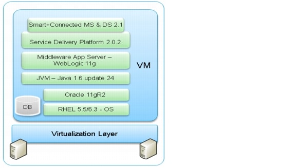
Colocated Server Setup
In a colocated deployment, all the functionalities and layers of the application reside on a single server.
This is the simplest form of the deployment, where the database and the application are installed on the same instance and the setup is self-contained. This is suitable for small enterprises.
Figure 1-2 Colocated Server Setup
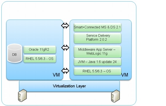
Non-cluster Server Setup
In this setup, the database and the application server are installed on two different instances—either on a physical or a virtual machine. This is a common server setup method for the enterprise installations. The database is setup on one instance and the application server, SDP, and the S+CC application are installed and set up on a second instance.
Figure 1-3 Non-Cluster Server Setup
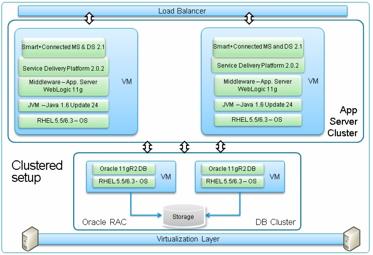
Cluster Server Setup
A cluster setup consists of multiple nodes that run an application simultaneously and work together to provide increased scalability, reliability, and high availability. In a distributed cluster setup, the solution is deployed on the multiple nodes of a cluster.
Figure 1-4 Cluster Server Setup
Deployment Flowchart
The deployment flowchart describes the procedure to deploy the solution and ensure a successful installation.
Figure 1-5 displays the deployment flowchart for a Colocated/ Non-cluster Server Setup .
Figure 1-5 Deployment Flowchart - Colocated/Non-cluster Server Setup
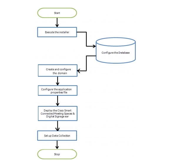
Figure 1-6 displays the deployment flowchart for a Cluster Server Setup.
Figure 1-6 Deployment Flowchart - Cluster Server Setup

 Feedback