Installation Overview
You can deploy the Cisco Tetration (Secure Workload) M4 cluster as either a 39-rack unit (RU) large-form factor platform (C1-Tetration) for data centers with more than 5000 servers or as an 8-RU small-form factor platform (C1-Tetration-M) for data centers with fewer than 5000 servers. Additionally, you can deploy the large-form factor platform in either one or two racks depending upon your requirements.
The Cisco Tetration (Secure Workload) M4 cluster deployments are configured as follows:
-
Large-form factor 39-RU Cisco Tetration (Secure Workload) platform in one rack (C1-Tetration single rack)
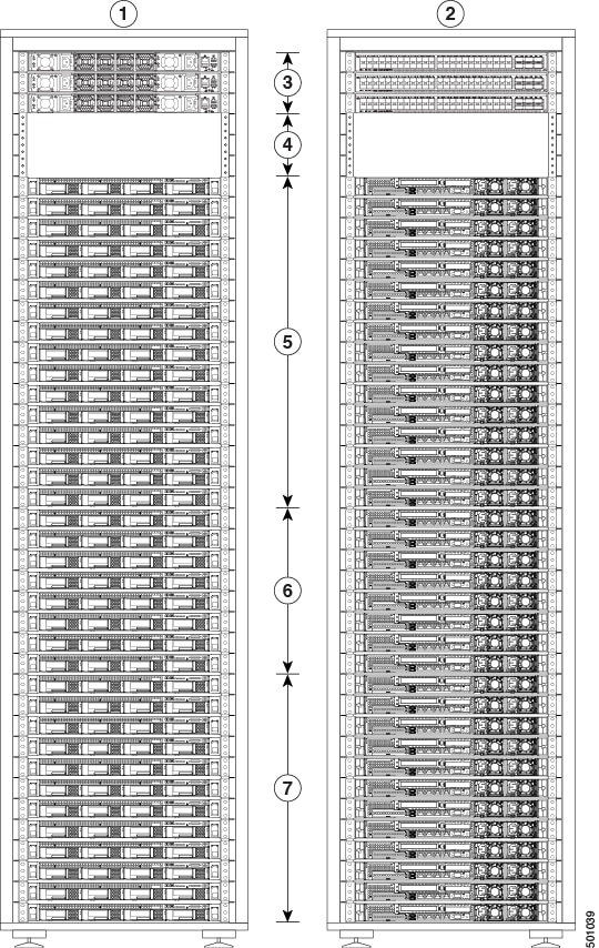
1
Cold aisle view
5
16 compute servers (RUs 21 to 36)
2
Hot aisle view
6
8 cache servers (RUs 13 to 20)
3
1 Spine (RU 42) and 2 leaf switches (RUs 40 and 41)
7
12 base servers (RUs 1 to 12)
4
Open rack units (RUs 37 to 39)
-
Large-form factor Cisco Tetration (Secure Workload) platform in two racks (C1-Tetration dual rack)
-
Rack 1
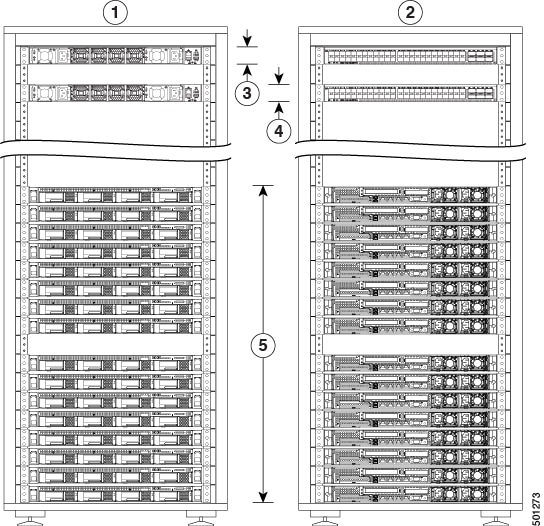
1
Cold aisle view
4
Leaf 1 switch (RU 40)
2
Hot aisle view
5
16 compute servers (RUs 1 to 4 and 6 to 9)
3
1 Spine switch (RU 42)
-
Rack 2
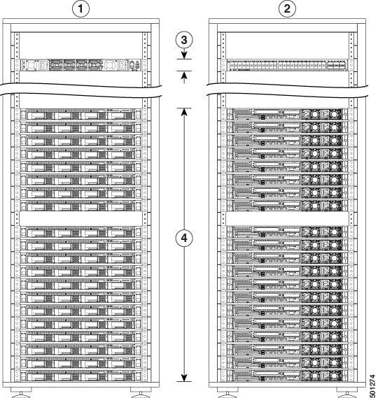
1
Cold aisle view
3
Leaf 2 switch (RU 40)
2
Hot aisle view
4
8 cache servers (RUs 14 to 21) and 12 base servers (RUs 1 to 12)
-
-
Small-form factor 8-RU Cisco Tetration (Secure Workload) platform in one rack (C1-Tetration-M)
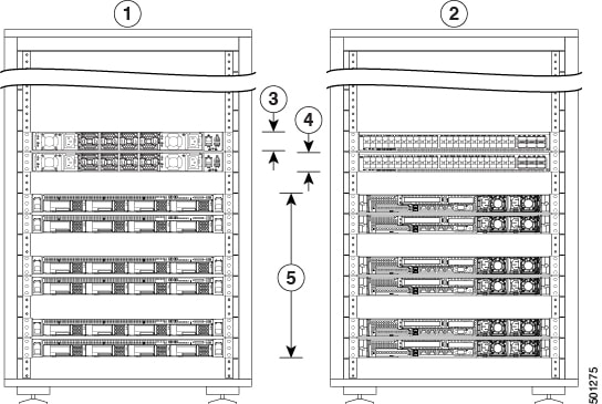
1
Cold aisle view
4
Leaf switch (RU 11)
2
Hot aisle view
5
6 universal servers (RUs 2, 3, 5, 6, 8, and 9)
3
Leaf switch (RU 12)
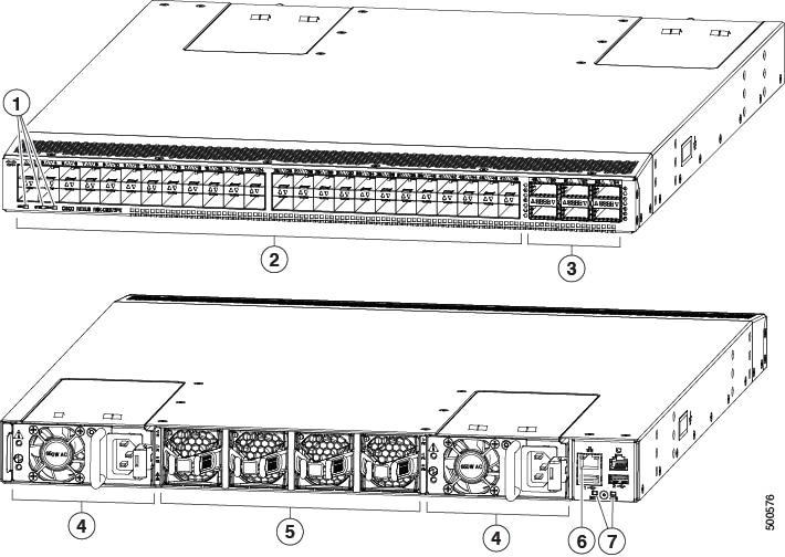
The switches have 48 10-Gigabit Ethernet ports numbered 1 to 48 and six 40-Gigabit Ethernet ports numbered 49 through 54. The following figure shows both ends of a switch and identifies these features.
|
1 |
Beacon (BCN), Status (STS), and Environment (ENV) LEDs |
5 |
Fan modules (blue handles indicate port-side exhaust airflow) |
|
2 |
10-Gigabit ports (48) numbered from 1 to 48 |
6 |
Management port |
|
3 |
40-Gigabit ports (6) numbered from 49 to 54 |
7 |
Beacon and Status (STS) LEDs |
|
4 |
AC Power supply (blue coloring indicates port-side exhaust airflow) |
— |
The large-form factor switches have servers that perform as compute, cache, and base nodes. The small-form factor switches have servers that perform as universal nodes. The following table specifies the characteristics of these servers.
|
Server Type |
Storage Drives in Each Server |
RAM |
RAID Cache |
|---|---|---|---|
|
Compute node (16 servers in the large-form factor platform) |
1.2-TB drive (1 in slot 1) 1.8-TB drives (7 in slots 2 to 8) |
512 GB |
4 GB |
|
Cache node (8 servers in the large-form factor platform) |
400-GB drives (8) |
512 GB |
2 GB |
|
Base node (12 servers in the large-form factor platform) |
1.2-TB drives (8) |
256 GB |
2 GB |
|
Universal node (6 servers in the small-form factor platform) |
1.6 TB SSD drives (5) 3.6 TB SSD drives (3) |
1024 GB |
2 GB |
For the servers, the 10-Gigabit interface ports (eth2, eth3, eth5, and eth4) are located in the two PCIe risers, and the management port is located below the PCIe risers as shown in the following figure.

|
1 |
PCIe riser 1 |
12 |
Drive bays |
|
2 |
eth2 port (first interface port) |
13 |
Pull-out asset tag |
|
3 |
eth3 port (second interface port) |
14 |
Power button/power status LED |
|
4 |
PCIe riser 2 |
15 |
Beacon LED |
|
5 |
eth5 port (fourth interface port) |
16 |
System status LED |
|
6 |
eth4 port (third interface port) |
17 |
Fan status LED |
|
7 |
Management interface |
18 |
Temperature status LED |
|
8 |
Serial port |
19 |
Power status LED |
|
9 |
eth0 port (CIMC port) |
20 |
Network activity LED |
|
10 |
eth1 port |
21 |
Console port |
|
11 |
AC Power supplies |
— |
 Feedback