Introduction
This document explains how to deploy the Threat Defense Virtual auto scale solution using GWLB on AWS to inspect north-south traffic
How to Set Up the Threat Defense Virtual Auto Scale Solution using GWLB on AWS to Inspect North-South Traffic
The auto scale solution enables the deployment, scaling, and management of a group of Threat Defense Virtual instances that are hosted for traffic inspection. The traffic is distributed across single or multiple Threat Defense Virtual instances depending on performance or usage capacity.
The GWLB acts as a single entry and exit point to manage internally and externally generated traffic and scales up or down the number of Threat Defense Virtual instances in real time based on traffic load.
 Note |
The parameter values used in this use case are sample values. Change these values as per your requirement. |
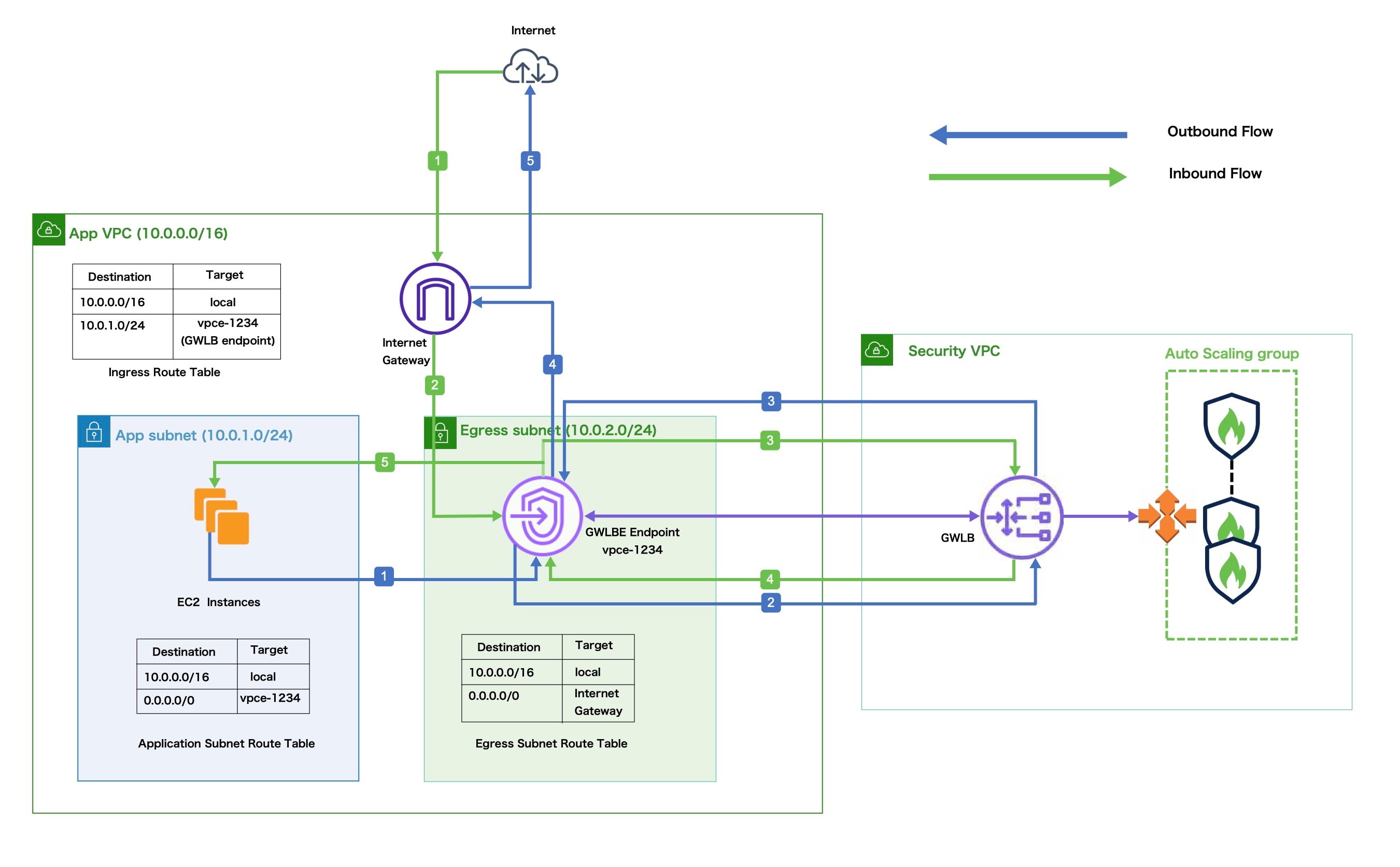
Sample Topology
This sample topology illustrates how inbound and outbound network traffic flow is distributed to Threat Defense Virtual instances through the GWLB and then routed to the application VPC and back.
|
Inbound Traffic Inspection |
|
|---|---|
|
|
The Internet Gateway (IGW) receives traffic from the Internet. |
|
|
Traffic is routed to the Gateway Load Balancer endpoint (GWLBe) as per the routes in the Ingress Route Table. |
|
|
The GWLBe is attached to the endpoint service in the Security Virtual Private Cloud (VPC). The GWLB encapsulates the received traffic and forwards it to the Threat Defense Virtual auto scaling group for inspection. |
|
|
The traffic inspected by the auto scaling group is returned to the GWLB and then to the GWLB endpoint. |
|
|
The GWLB endpoint forwards the traffic to the Application VPC from where it is routed to the resources in the Application subnet. |
|
Outbound Traffic Inspection |
|
|---|---|
|
|
Traffic from the Application subnet resources is routed to the GWLBe in the same VPC. |
|
|
The GWLBe is attached to the endpoint service in the Security VPC. The GWLB encapsulates the received traffic and forwards the same to the auto scaling group for inspection. |
|
|
The traffic inspected by the auto scaling group is returned to the GWLB and then to the GWLBe. |
|
|
After the traffic arrives in the origin VPC, it is forwarded to the IGW as per the routes defined in the Egress Subnet Route Table. |
|
|
The IGW sends the traffic to the Internet. |
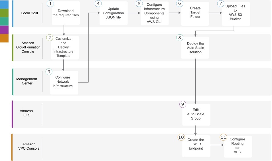
End-to-End Procedure
The following flowchart illustrates the workflow for deploying Threat Defense Virtual auto scale solution with GWLB on Amazon Web Services (AWS).
|
Workspace |
Steps |
|
|---|---|---|
|
Local Host |
||
|
Amazon CloudFormation Console |
||
|
Management Center |
||
|
Local Host |
||
|
Local Host |
||
|
Local Host |
||
|
Local Host |
||
|
Amazon CloudFormation Console |
||
|
Amazon EC2 Console |
||
|
Amazon VPC Console |
||
|
Amazon VPC Console |
Prerequisites
-
Clone the GitHub repository to your local host from GitHub. This repository contains the following files under cisco-ftdv/autoscale/aws.
-
Python (.py) files that are used to create the lambda layer.
-
A configuration.json file that is used to add static routes and customize any network parameters, as required.
-
The make.py to generate zip files.
-
The *.yaml files is required for deployment.
-
-
Cloud formation templates under /templates folder:
-
infrastructure_gwlb.yaml – Used to customize the components in the AWS environment.
-
deploy_ngfw_autoscale_with_gwlb.yaml – Used to deploy the AWS Auto Scale with GWLB solution.
-
-
[Optional] Collect values for the template parameters, wherever possible. This will make it easier to enter the values quickly while deploying the templates on the AWS Management console.
Amazon CloudFormation console – Customize and Deploy the Infrastructure Template
Perform the steps given in this section to customize and deploy the infrastructure template.
Procedure
|
Step 1 |
On the AWS Management console, go to , and click . |
||||||||||||||||||||||||||||||||||
|
Step 2 |
Choose Upload a template file, click Choose file, and select infrastructure_gwlb.yaml from the folder in which you downloaded the files. |
||||||||||||||||||||||||||||||||||
|
Step 3 |
Click Next |
||||||||||||||||||||||||||||||||||
|
Step 4 |
On the Specify stack details page, enter a name for the stack. |
||||||||||||||||||||||||||||||||||
|
Step 5 |
Provide values for the input parameters in the infrastructure_gwlb.yaml template.
|
||||||||||||||||||||||||||||||||||
|
Step 6 |
Click Next. |
||||||||||||||||||||||||||||||||||
|
Step 7 |
Click Next on the Configure Stack Options window. |
||||||||||||||||||||||||||||||||||
|
Step 8 |
On the Review page, review and confirm the settings. |
||||||||||||||||||||||||||||||||||
|
Step 9 |
Click Create Stack to deploy the infrastructure_gwlb.yaml template and create the stack. |
||||||||||||||||||||||||||||||||||
|
Step 10 |
After the deployment is complete, go to Outputs and note the S3 Bucket Name. |
Management Center - Configure Network Infrastructure in Management Center for Threat Defense Virtual
Create and configure objects, device droups, health check port, and access policies, in the Management Center for the registered Threat Defense Virtual.
Add Users
Procedure
|
Step 1 |
Log in to the Management Center. You must create two user accounts in the management center: one for Autoscale automation and the other for user publishing metrics to CloudWatch. |
|
Step 2 |
Choose . |
|
Step 3 |
To create a new user:
|
|
Step 4 |
Enter values in the Password and Confirm Password fields. The values must conform to the password options you set for this user. |
|
Step 5 |
In the User Role Configuration area, check the Administrator check box. Note down these user credentials to use when deploying the Autoscale Solution Template. You need to mention these user credentials in the FMC Automation Configuration and FMC Device Group Metrics Publish Configuration. |
|
Step 6 |
Click Save. |
Create a Host object
Procedure
|
Step 1 |
Log in to the Management Center. |
|
Step 2 |
Choose . |
|
Step 3 |
Choose Network from the list of object types. |
|
Step 4 |
Choose Add Object from the Add Network drop-down menu. |
|
Step 5 |
Enter a Name - aws-metadata-server. |
|
Step 6 |
Enter a Description. |
|
Step 7 |
In the Network field, select the Host option and enter the IPv4 address - 169.254.169.254. |
|
Step 8 |
Click Save. |
Create a Port object
Procedure
|
Step 1 |
Log in to the Management Center. |
||
|
Step 2 |
Choose . |
||
|
Step 3 |
Choose Port from the list of object types. |
||
|
Step 4 |
Choose Add Object from the Add Port drop-down menu. |
||
|
Step 5 |
Enter a Name - test-port-object. |
||
|
Step 6 |
Choose a Protocol. You must choose the protocol that you have entered for the Host object type. Depending on the protocol you chose, constrain by Port. |
||
|
Step 7 |
Enter 8080. Note that you can customise the port number that you enter here as per your requirement.
|
||
|
Step 8 |
Click Save. |
Add Device Group
The Management Center allows you to group devices so you can easily deploy policies and install updates on multiple devices. You can expand and collapse the list of devices in the group.
Procedure
|
Step 1 |
Choose . |
|
Step 2 |
From the Add drop-down menu, choose Add Group. |
|
Step 3 |
To edit an existing group, click Edit (edit icon) for the group you want to edit. |
|
Step 4 |
Enter a Name - aws-ngfw-autoscale-dg. |
|
Step 5 |
Click OK to add the device group. |
Create Security Zones
Procedure
|
Step 1 |
Choose . |
|
Step 2 |
Choose Interface from the list of object types. |
|
Step 3 |
Click . |
|
Step 4 |
Enter a Name - Inside-sz. |
|
Step 5 |
Choose Routed from the Interface Type drop-down list. |
|
Step 6 |
Click Save. |
|
Step 7 |
Similarly, you must create Outside-sz by repeating Step 1 through Step 6. |
Enable Port 22 (SSH) for Health Check Probe
If you are using port 22 (SSH) for the health check probe, perform the following procedure to enable the port for the health check probe.
Procedure
|
Step 1 |
Choose . |
|
Step 2 |
Provide the policy name. |
|
Step 3 |
Select the device group that you have created - aws-ngfw-autoscale-dg from the Targeted Devices drop-down list. |
|
Step 4 |
Click Save. |
|
Step 5 |
Click on the newly created policy and select SSH Access from the left pane. |
|
Step 6 |
Click + Add. |
|
Step 7 |
Select any from the IP Address drop-down list. |
|
Step 8 |
From the Available Zones/Interfaces window, select the Outside-sz. |
|
Step 9 |
Click Add to add that interface to the Selected Zones/Interfaces window. |
|
Step 10 |
Click OK. |
|
Step 11 |
Click Save. |
Create a Basic Access Control Policy
When you create a new access control policy, it contains default actions and settings. After creating the policy, you are immediately placed in an edit session so that you can adjust the policy to suit your requirements.
Procedure
|
Step 1 |
Choose . |
|
Step 2 |
Click New Policy. |
|
Step 3 |
Enter a unique Name - aws-asg-policy and Description. |
|
Step 4 |
Specify the initial Default Action - Block all traffic. |
|
Step 5 |
Click Save. |
|
Step 6 |
Click the Targeted Devices on the upper right side of the page to assign the policy. |
|
Step 7 |
Select aws-ngfw-autoscale-dg from the available devices. |
|
Step 8 |
Click Add to Policy and then click OK to add to policy. |
|
Step 9 |
Click the Edit icon for the new policy that you created. |
|
Step 10 |
Click Add Rule. |
|
Step 11 |
Set the following parameters:
|
|
Step 12 |
Click Apply. |
Local Host - Update the Configuration JSON File
The configuration.json file is in the lambda_python_files folder that you downloaded from GitHub. Update the parameters in the configuration.json file with the parameters set up by you in the management center.
The scripts in the configuration.json file are as given below.
"licenseCaps": ["BASE", "MALWARE", "THREAT"],   // Management center virtual licenses
  "fmcIpforDeviceReg": "DONTRESOLVE",   // Management center virtual IP address
  "RegistrationId": "cisco",  // Registration ID used while configuring the manager in the Threat defense virtual
  "NatId": "cisco",  // NAT ID used while configuring the manager in the Threat defense virtual
  "fmcAccessPolicyName": "aws-asg-policy",  // Access policy name configured in the Management center virtual
  "fmcInsideNicName": "inside", //Threat defense virtual inside interface name
  "fmcOutsideNicName": "outside", //Threat defense virtual outside interface name
  "fmcInsideNic": "TenGigabitEthernet0/0", // Threat defense virtual inside interface NIC Name - GigabitEthernet for c4 instance types, and TenGigabitEthernet for c5 instance types)
  "fmcOutsideNic": "TenGigabitEthernet0/1", // Threat defense virtual outside interface NIC Name - GigabitEthernet for c4 instance types, and TenGigabitEthernet for c5 instance types
  "fmcOutsideZone": "Outside-sz", //Outside Interface security zone name that is set in the Management center virtual
  "fmcInsideZone": "Inside-sz", //Inside Interface security zone name that is set in the Management center virtual
  "interfaceConfig": [
    {
      "managementOnly": "false",
      "MTU": "1500",
      "securityZone": {
        "name": "Inside-sz"
      },
      "mode": "NONE",
      "ifname": "inside",
      "name": "TenGigabitEthernet0/0"
    },
    {
      "managementOnly": "false",
      "MTU": "1500",
      "securityZone": {
        "name": "Outside-sz"
      },
      "mode": "NONE",
      "ifname": "outside",
      "name": "TenGigabitEthernet0/1"
    }
  ],  // Interface-related configuration
  "trafficRoutes": [
    {
      "interface": "inside",
      "network": "any-ipv4",
      "gateway": "",
      "metric": "1"
    }
  ] // This traffic route is used for the Threat defense virtual instance's health check
}
Note |
To use a private IP for registering Threat Defense Virtual with Management Center Virtual, modify the following line in the constant.py file located in cisco-ftdv/autoscale/aws/lambda-python-files/:
|
Ubuntu Host - Configure Infrastructure Components using AWS CLI
The templates do not create the Lambda layer and encrypted passwords for the threat defense virtual and management center. Configure these components using the procedures given below. See AWS Command Line Interface for more information on the AWS CLI.
Procedure
|
Step 1 |
Create Lambda Layer Zip File. Create a python folder on your Linux host and then create the Lambda layer. |
|
Step 2 |
(Optional) Create Encrypted Passwords for the Threat Defense Virtual and Management Center. If a KMS ARN value has been entered in the infrastructure_gwlb.yaml template file, the passwords that you set up in the threat
defense virtual and management centre have to be encrypted. See Finding the key ID and key ARN to identify the key ARN using the AWS KMS console. On your local host, encrypt the password by running the following AWS
CLI command.
CiphertextBlob is the encrypted password. Use this password as the value of the NGFWv Password (threat defense virtual password) or the FMC Password for AutoScale Automation (management center password) parameter in theinfrastructure_gwlb.yaml file. You can also use this password as the value of the FMC Password for Publishing Metrics to CloudWatch.
|
Local Host – Create Target Folder
Navigate to cisco-ftdv/autoscale/aws/ in the cloned repository on your local host, and run the command given below to create a target folder containing the files that have to be uploaded to the Amazon S3 bucket.
python3 make.py build
This creates a folder named ‘target’ on your local host. The target folder contains the zip files and yaml files required for the deployment of the auto scale solution.
Local Host - Upload AWS GWLB Auto Scale Solution Deployment Files to the Amazon S3 Bucket
Use the command given below to upload all the files in the target directory to the Amazon S3 bucket created during infrastructure stack deployment.
$ cd ./target
$ aws s3 cp . s3://demo-us-bkt --recursive
Amazon CloudFormation console - Deploy the Auto Scale Solution for the Threat Defense Virtual using GWLB
Procedure
|
Step 1 |
On the AWS Management console, go to and click the stack that was created by the template. |
||||||||||||||||||||||||||||||||||||||||||||||||||||||||||||||||||||||||||||||||||||||
|
Step 2 |
Click . |
||||||||||||||||||||||||||||||||||||||||||||||||||||||||||||||||||||||||||||||||||||||
|
Step 3 |
Select Upload a template file, click Choose File, and select deploy_ngfw_autoscale_with_gwlb.yaml from the target folder. |
||||||||||||||||||||||||||||||||||||||||||||||||||||||||||||||||||||||||||||||||||||||
|
Step 4 |
Click Next. |
||||||||||||||||||||||||||||||||||||||||||||||||||||||||||||||||||||||||||||||||||||||
|
Step 5 |
On the Specify stack details page, enter a name for the stack. |
||||||||||||||||||||||||||||||||||||||||||||||||||||||||||||||||||||||||||||||||||||||
|
Step 6 |
Provide values for the input parameters in the deploy_ngfw_autoscale_with_gwlb.yaml template. Stack Name: Threat-Defense-Virtual
|
||||||||||||||||||||||||||||||||||||||||||||||||||||||||||||||||||||||||||||||||||||||
|
Step 7 |
Click Next on the Configure Stack Options window. |
||||||||||||||||||||||||||||||||||||||||||||||||||||||||||||||||||||||||||||||||||||||
|
Step 8 |
On the Review page, review and confirm the settings. |
||||||||||||||||||||||||||||||||||||||||||||||||||||||||||||||||||||||||||||||||||||||
|
Step 9 |
Click Create Stack to deploy the deploy_ngfw_autoscale_with_gwlb.yaml template and create the stack. |
Amazon EC2 console - Edit the Number of Instances in the Auto Scale Group
By default, the Auto Scale group has the minimum and maximum number of threat defense virtual instances set to 0 and 2 respectively. Change these values as per your requirement.
Procedure
|
Step 1 |
On the AWS Management console, go to , and click Auto Scaling Groups. |
|
Step 2 |
Select the auto scaling group created by you and click Edit to modify the values in the Desired capacity, Minimum capacity, Maximum capacity fields as per your requirement. These values correspond to the number of threat defense virtual instances that you want to bring up for the auto scaling functionality. Set the Desired capacity to a value that is within the minimum and maximum capacity values. |
|
Step 3 |
Click Update. |
Note |
We recommend that you launch only one threat defense virtual instance and verify that the instance is InService in the autoscale group and registered to Management Center Virtual. You can then launch more instances as per your requirement. |
Amazon VPC dashboard console - Create the GWLB Endpoint and Configure Routing for the Customer VPC
You have to create the GWLB endpoint and configure routing for the customer VPC after deploying both the CloudFormation templates.
Create the GWLB Endpoint
Procedure
|
Step 1 |
On the AWS Management console, go to . |
|
Step 2 |
Click Create Endpoint Service |
|
Step 3 |
Under Load balancer type, choose Gateway. |
|
Step 4 |
Under Available load balancers, choose the Gateway Load balancer that was created as part of the Auto scale deployment. |
|
Step 5 |
Click Create. |
|
Step 6 |
Copy the Service name of the newly created endpoint service. |
|
Step 7 |
Go to . |
|
Step 8 |
Click Create endpoint. |
|
Step 9 |
Under Service category, choose Other endpoint services. |
|
Step 10 |
For Service name, enter the name of the service, and then choose Verify service. |
|
Step 11 |
In the VPC field, select the VPC, App VPC, in which to create the endpoint. |
|
Step 12 |
Under Subnets, select the subnet, Egress subnet, in which to create the endpoint. |
|
Step 13 |
For IP address type, choose the IPv4 option to assign IPv4 addresses to the endpoint network interfaces. |
|
Step 14 |
Click Create endpoint. |
|
Step 15 |
Go to , click the Endpoint Connections tab, choose the Endpoint ID that you created earlier, and click Actions > Accept endpoint connection request. |
Configure Routing for the Customer VPC
Procedure
|
Step 1 |
On the AWS Management console, go to . |
|
Step 2 |
Create the Ingress Route Table and perform the following steps:
|
|
Step 3 |
Select the route table for the subnet with the application servers and perform the following steps:
|
|
Step 4 |
Select the route table for the subnet with the Gateway Load Balancer endpoint, and perform the following steps:
|
Amazon CloudWatch - Validate Deployment
Once the template deployment is successful, go to the Amazon CloudWatch console to ensure that logs are being collected and the required alarms have been created.
Logs
Check the log files to troubleshoot any issues with Management Center connectivity.
Procedure
|
Step 1 |
On the AWS Management console, go to . |
|
Step 2 |
Click Log groups and click any log group displayed here to view the logs. |
Alarms
Ensure that the required alarms have been created on the Amazon CloudWatch console.
Procedure
|
Step 1 |
On the AWS Management console, go to . |
|
Step 2 |
Click to display the list of alarms along with the conditions which will trigger the scale-out and scale-in functions. |
 Feedback