Cisco Video Surveillance 8000P IP Camera Reference Guide, Release 1.0.5
Bias-Free Language
The documentation set for this product strives to use bias-free language. For the purposes of this documentation set, bias-free is defined as language that does not imply discrimination based on age, disability, gender, racial identity, ethnic identity, sexual orientation, socioeconomic status, and intersectionality. Exceptions may be present in the documentation due to language that is hardcoded in the user interfaces of the product software, language used based on RFP documentation, or language that is used by a referenced third-party product. Learn more about how Cisco is using Inclusive Language.
- Updated:
- March 6, 2019
Chapter: Getting Started
Getting Started
This chapter provides information about getting started with and understanding the IP camera. It includes the following sections:
Overview
The Cisco Video Surveillance 8000P IP Camera is a high-definition, full-functioned video endpoint with industry-leading image quality and processing power. The camera is capable of 5MP resolution at 30 frames per second (fps) while optimizing network usage with either H.264, H.265, or MJPEG compression. Contact closures and two-way audio allow integration with microphones, speakers, and access control systems. With its open, standards-based design, the camera provides an ideal platform for integration and operation as an independent device or as part of a Cisco video surveillance network.
Key features and benefits of the Cisco Video Surveillance 8000P IP Camera include:
- True high-definition video—The camera streams crisp and clear 5MP video at 30 fps while maintaining low network bandwidth
- Streaming—The camera supports up to four H.264, H.265, and MJPEG video streams simultaneously, and each video stream can be configured with individual resolution, quality, and frame-rate settings
- Day/night operation—The camera provides true day/night functionality, which can be set to manual, automatic, or scheduled control, and includes an infrared (IR) filter that automatically switches to night mode in low-light scenes
- Flexible power option—The camera supports Power over Ethernet (PoE) 802.3af or 12 VDC
- Mounting options—The camera can be installed to either a ceiling or wall
- Motion Detection and Event notification—The camera can examine designated areas for activity and notify users or other applications when it detects activity that exceeds a predefined sensitivity and threshold
Physical Description
Figure 1-1 illustrates the front panel of the Cisco Video Surveillance 8000P IP Camera. Figure 1-2 illustrates the rear panel of the camera.
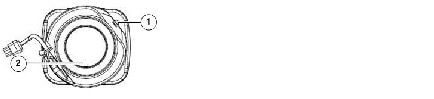
Figure 1-1 IP Camera Front Panel
|
|
|
|
|
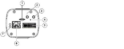
Figure 1-2 IP Camera Rear Panel
|
|
|
|
|
|
|
|
|
|
|
|
|
|
|
|
|
|
|
|
Power Adapters
This product is intended to be supplied by a Listed Power Adapter with LPS, rated 12Vdc, 0.72A or 24Vac, 0.8A, 50-60Hz or PoE 36~57Vdc, 0.3-0.2A |
Hardware Installation
To perform the hardware installation of the Cisco Video Surveillance IP Camera, follow these steps:
Step 1![]() Make a note of the MAC address of the camera.
Make a note of the MAC address of the camera.
The MAC address is printed on the label that is attached to the camera.
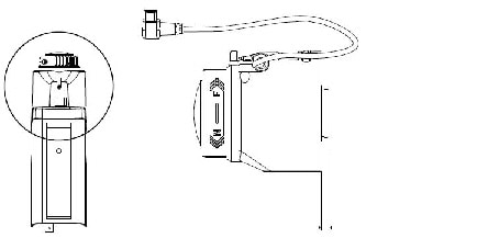
Step 2![]() Install the lens module on the camera.
Install the lens module on the camera.
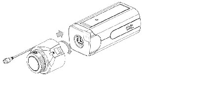
Step 3![]() Connect the iris control cable to the socket on camera.
Connect the iris control cable to the socket on camera.
Step 4![]() Remove the protection sheet from the light sensor.
Remove the protection sheet from the light sensor.

Fasten the lens module to the camera, and notice that the lens module does not block the light sensor. You can still turn the camera when the lens module is secured to the camera.
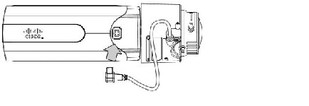
Step 5![]() Attach the camera stand to the camera.
Attach the camera stand to the camera.
Step 6![]() Connect an Ethernet cable to the camera.
Connect an Ethernet cable to the camera.
The screw mount must be shorter than 5.2mm; in case that the bottom of screw mount may hit the IR Cut Filter.
Step 7![]() Install a MicroSD card, and, if preferred, connect DI/DO wires to the terminal block The AC/DC pins can accept either 12V or 24V power input with no polarity.
Install a MicroSD card, and, if preferred, connect DI/DO wires to the terminal block The AC/DC pins can accept either 12V or 24V power input with no polarity.
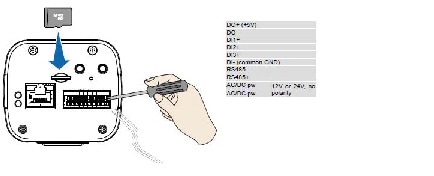
The DO pin can provide a 5V output, and the max. load is 50mA.
- The DO+ pin provides 5V output voltage, and the max. load is 50mA.
- The max. voltage for DO- pins is 80VDC (External power). In order to control AC devices, the above diagram can be taken in consideration. The diagram uses a relay to control the ON/OFF condition of the AC device.
- An external relay can be triggered by using DO+ or by an external power source, depending on the type of relay you use.
- In case of using an individual relay (instead of using a relay module), for protection against voltage or current spikes, a transient voltage suppression diode must be connected in parallel with the inductive load.
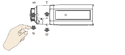
Step 8![]() With a live view on screen, adjust the image zoom and focus using the pullers on lens module.
With a live view on screen, adjust the image zoom and focus using the pullers on lens module.
LED Definitions
Table 1-1 describes the LEDs on the Cisco Video Surveillance IP Camera.
Hardware Reset
The recessed reset button (see Figure 1-2) is used to reset the system or restore the factory default settings. Sometimes resetting the system can return the camera to normal operation. If the system problems remain after reset, restore the factory settings and install again.
MicroSD/SDHC/SDXC Card Capacity
The camera is compliant with SD/SDHC/SDXC 16GB / 8GB / 32GB / 64GB and other preceding standard SD cards.
Network Deployment
The following sections provide information about deploying the camera on a network:
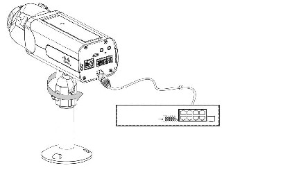
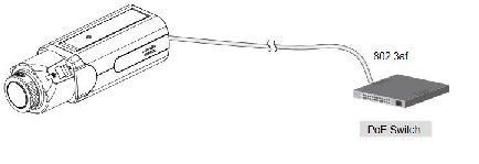
General Connection (PoE)
The camera is PoE-compliant, allowing transmission of power and data via a single Ethernet cable. Figure 1-4 illustrates how to connect the camera to a PoE-enabled switch via an Ethernet cable.
Figure 1-4 Connecting the Camera to a PoE-Enabled Switch
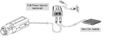
Use a PoE power injector (optional) to connect between the camera and a non-PoE switch, as shown in Figure 1-5.
Figure 1-5 Connecting the Camera to a Non-PoE Switch

Note ●![]() The camera is only to be connected to PoE networks without routing to outside plants.
The camera is only to be connected to PoE networks without routing to outside plants.
Network Connection
Internet Connection via a Router
To set up the camera over the Internet, make sure you have a router and follow these steps:
Step 1![]() Connect your camera behind a router, the Internet environment is illustrated in Figure 1-6.
Connect your camera behind a router, the Internet environment is illustrated in Figure 1-6.
Figure 1-6 Connecting the Camera Via a Router
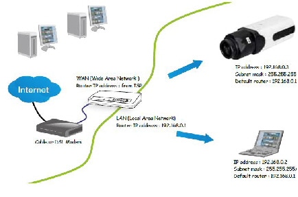
Step 2![]() In this case, if the Local Area Network (LAN) IP address of your camera is 192.168.0.3, forward the following ports for the camera on the router.:
In this case, if the Local Area Network (LAN) IP address of your camera is 192.168.0.3, forward the following ports for the camera on the router.:
If you have changed the port numbers on the Network page, open the ports accordingly on your router. For information about how to forward ports on the router, see your router documentation.
Step 3![]() Find out the public IP address of your router provided by your Internet Service Provider (ISP).
Find out the public IP address of your router provided by your Internet Service Provider (ISP).
Use the public IP and the secondary HTTP port to access the camera from the Internet. See the “Network > General settings” section for more information.
Internet Connection with Static IP
Choose this connection type if you are required to use a static IP for the camera. See the “Network > General settings” section for more information.
Internet Connection via Point-to-Point over Ethernet (PPPoE)
Choose this connection type if you are connected to the Internet via a DSL Line. See description of PPPoE (Point-to-point over Ethernet) in the “Network Type Tab” section.
Configure the router, virtual server or firewall, so that the router can forward any data coming into a preconfigured port number to a camera on the private network, and allow data from the camera to be transmitted to the outside of the network over the same path.
|
|
|
|---|---|
When properly configured, you can access a camera behind the router using the HTTP request such as: http://122.146.57.120:8000.
If you change the port numbers on the Network configuration page, open the ports accordingly on your router. For example, you can open a management session with your router to configure access through the router to the camera within your local network. See your network administrator for router configuration if you have troubles with the configuration.
For more information about network configuration options (such as that of streaming ports), choose Configuration > Network Settings in the IP camera web-based interface. Cisco also provides the automatic port forwarding feature as an NAT traversal function with the precondition that your router must support the UPnP port forwarding feature.
Auto Focus
On the web session, choose Configuration > Media > Image > Focus. Perform the Auto Focus function for best image. However, if you have cascaded cameras, do this one by one. Do not perform this function simultaneously on multiple cameras because the motorized lens also consume considerable power, and may cause the last camera on the line to hang.
 Feedback