Cisco Video Surveillance 7030E IP Camera Installation Guide
Bias-Free Language
The documentation set for this product strives to use bias-free language. For the purposes of this documentation set, bias-free is defined as language that does not imply discrimination based on age, disability, gender, racial identity, ethnic identity, sexual orientation, socioeconomic status, and intersectionality. Exceptions may be present in the documentation due to language that is hardcoded in the user interfaces of the product software, language used based on RFP documentation, or language that is used by a referenced third-party product. Learn more about how Cisco is using Inclusive Language.
- Updated:
- May 13, 2014
Chapter: Overview
Overview
This chapter describes the Cisco Video Surveillance 7030E IP Camera, and includes the following topics:
Introduction
The Cisco Video Surveillance 7030E IP camera is an outdoor, high definition, professional fixed dome IP camera with industry-leading image quality and processing power. The 5 megapixel (MP) IP camera offers 1080p full HD resolution (up to 2560 x 1920) with superb image quality up to 30 frames per second (FPS) while optimizing network usage with either H.264 or MJPEG compression. It can capture a much more comprehensive area than a standard VGA model, significantly reducing the number of units required. It is especially suitable for monitoring wide open outdoor areas such as building entrances, airports, or applications requiring accurate identification.
For installers, properly adjusting the focus of an HD IP camera can be difficult due to the image detail. To make installation and adjustment easier, the 7030E IP camera incorporates built-in stepping motors that the installer can use to remotely control the focal length and precisely adjust the camera focus, offering hassle-free installation and maintenance.
For complete installation and tampering prevention, the 7030E IP camera also fits different conduits and corrugated tubes sizes for cable installation. Its IP67-rated housing is designed to help the camera body withstand rain and dust and ensures operation under a multitude of harsh weather conditions. The wide temperature range further enhances the 7030E IP camera performance and reliability in extremely cold and warm weather. Additionally, the metal vandal-proof housing effectively provides robust protection from vandalism.
With other advanced features such 802.3af compliant PoE, micro SD/SDHC card for local storage, integrated IR illuminator for enhanced visibility in night mode, and e-PTZ functionality, the 7030E IP camera provides the most robust solution suitable for any demanding outdoor environment.
Package Contents
The Cisco Video Surveillance IP Camera package includes the following items:
- Cisco Video Surveillance 7030E IP Camera (1)
- Installation alignment sticker (1)
- Mounting plate (1)
- Black cover (1)
- Bushing (1)
- Waterproof connector (1)
- L type hex key (allen wrench) (1)
- Screws (t4x32) (4)
- Wall anchors (4)
- Hex nut (1)
- Double sided tape (1)
- Silica gel packet (1)
- Extra set of labels (3)
- Cisco documentation pointer card (1)
- Cisco RoHS document (1)
IP Camera Physical Details
Figure 1-1 and the table that follows describe the physical features of the 7030E IP camera.
Figure 1-1 IP Camera Physical Features
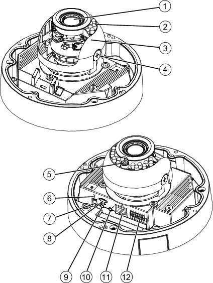
IP camera lens that changes focus as the focal length changes. |
||
Infrared illuminator LEDs that enhance the video image (effective up to 60 ft. [20 m]) when the IP camera is running in night mode. |
||
A dark cover with a cutout for the camera lens that makes it difficult to see where the IP camera is pointed. Note You must temporarily remove the black cover when adjusting the camera field of view. |
||
Senses the level of ambient light to determine when to switch day/night mode. |
||
Recessed button that reboots the IP camera or resets it to a default state. You can use a pin or paper clip to depress it. It can be used any time that the IP camera is on and can have various effects, as described in the “Resetting the IP Camera” section on page 2-11. |
||
Note There is no internal microphone. You must connect an external microphone if you require audio inputs. |
||
Support for the SD/SDHC card slot will be available in future releases. |
||
Allows the connection of an optional Y cable or mini cable with BNC connector. You can connect a video monitor to the mini cable with BNC connector. Both cables are included in the optional audio/video cables accessory kit can be purchased from Cisco (Cisco part number CIVS-AVCABLE). |
||
Accepts a standard LAN cable to connect the IP camera to a 10/100BaseT router or switch. |
||
General purpose input/output (GPIO) terminal block that is used to connect external input and output devices. For more information, see Figure 1-2. |
General Purpose I/O Terminal Block
Figure 1-2 shows the GPIO terminal block pin locations and descriptions.
Figure 1-2 GPIO Terminal Block Pin Locations and Descriptions
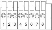

Note The maximum output load from pins 7 and 8 is 50mA.
 Feedback