Cisco Video Surveillance 6400 IP Camera Installation Guide
Bias-Free Language
The documentation set for this product strives to use bias-free language. For the purposes of this documentation set, bias-free is defined as language that does not imply discrimination based on age, disability, gender, racial identity, ethnic identity, sexual orientation, socioeconomic status, and intersectionality. Exceptions may be present in the documentation due to language that is hardcoded in the user interfaces of the product software, language used based on RFP documentation, or language that is used by a referenced third-party product. Learn more about how Cisco is using Inclusive Language.
- Updated:
- October 14, 2012
Chapter: Camera Installation
Camera Installation
This chapter provides information and instructions for installing the Cisco Video Surveillance 6400 IP Camera, and includes the following topics:
•![]() Connecting External Power and I/O Cables
Connecting External Power and I/O Cables
•![]() Connecting a Waterproof Ethernet Cable
Connecting a Waterproof Ethernet Cable
Installation Guidelines
This section describes how to install the IP camera. Before installing, review these guidelines:
•![]() The IP camera requires a network cable and a connection to a standard 10/100BaseT router or switch. To power the IP camera with Power over Ethernet (PoE), a switch must be 802.3af compliant.
The IP camera requires a network cable and a connection to a standard 10/100BaseT router or switch. To power the IP camera with Power over Ethernet (PoE), a switch must be 802.3af compliant.
•![]() If you are using the IP camera on a network connection that does not provide PoE, you must use a Cisco 12 VDC power adapter (Cisco part number CIVS-PWRPAC-12V) or a third-party 24 VAC power adapter.
If you are using the IP camera on a network connection that does not provide PoE, you must use a Cisco 12 VDC power adapter (Cisco part number CIVS-PWRPAC-12V) or a third-party 24 VAC power adapter.
•![]() If you are using an input device, output device, or pan/tilt control device, you must configure additional settings after installing and performing the initial set up of the IP camera before the external device can fully operate. For detailed information about these settings, see the Cisco Video Surveillance 6000 Series IP Camera Configuration Guide.
If you are using an input device, output device, or pan/tilt control device, you must configure additional settings after installing and performing the initial set up of the IP camera before the external device can fully operate. For detailed information about these settings, see the Cisco Video Surveillance 6000 Series IP Camera Configuration Guide.
•![]() If you do not connect an external device (input, output, or pan/tilt control) when you perform the following installation procedure, you can install any of these devices later.
If you do not connect an external device (input, output, or pan/tilt control) when you perform the following installation procedure, you can install any of these devices later.
Warnings Before Installation
 |
Warning |
|
Warning |

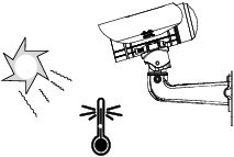
Note ![]() If you use the IP camera outdoors, place the camera and the power supply in a suitable NEMA enclosure.
If you use the IP camera outdoors, place the camera and the power supply in a suitable NEMA enclosure.
|
Warning |

Note ![]() The power adapter that you use with the IP camera must provide power that is within +/-10% of the required power.
The power adapter that you use with the IP camera must provide power that is within +/-10% of the required power.
Note ![]() The equipment is to be connected to a Listed class 2, limited power source.
The equipment is to be connected to a Listed class 2, limited power source.
Installing the IP Camera
To install the Cisco Video Surveillance 6400 IP Camera, perform the following steps.
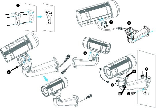
Note ![]() Use Figure 2-1 as a visual reference for the following procedure.
Use Figure 2-1 as a visual reference for the following procedure.
Procedure
Step 1 ![]() Attach the alignment sticker to the wall. Drill three mounting holes and one larger cabling hole into the wall, hammer the three included wall anchors into the holes, and secure the mounting plate with included screws.
Attach the alignment sticker to the wall. Drill three mounting holes and one larger cabling hole into the wall, hammer the three included wall anchors into the holes, and secure the mounting plate with included screws.
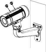
Step 2 ![]() Attach the camera anchor bracket to the side of the IP camera with the two included screws.
Attach the camera anchor bracket to the side of the IP camera with the two included screws.
Step 3 ![]() (Optional) If you want to use an external power source for the 6400 IP camera, or use external devices such as sensors and alarms, complete the steps in the "Connecting External Power and I/O Cables" section before continuing to Step 4.
(Optional) If you want to use an external power source for the 6400 IP camera, or use external devices such as sensors and alarms, complete the steps in the "Connecting External Power and I/O Cables" section before continuing to Step 4.
Step 4 ![]() Feed the cable with an RJ 45 jack through the front opening of the wall mount bracket.
Feed the cable with an RJ 45 jack through the front opening of the wall mount bracket.
Step 5 ![]() Push the spring mortise and hook the camera anchor bracket onto the groove of the wall mount bracket.
Push the spring mortise and hook the camera anchor bracket onto the groove of the wall mount bracket.
Step 6 ![]() Secure the two screws on the other side of the wall mount bracket.
Secure the two screws on the other side of the wall mount bracket.
Step 7 ![]() Hang the wall mount bracket on the mounting plate.
Hang the wall mount bracket on the mounting plate.
Step 8 ![]() Secure the wall mount bracket to the mounting plate with the included screw.
Secure the wall mount bracket to the mounting plate with the included screw.
Step 9 ![]() Connect the RJ45 jack to your network using an Ethernet cable, or to ensure a waterproof network connection, complete the steps in the "Connecting a Waterproof Ethernet Cable" section.
Connect the RJ45 jack to your network using an Ethernet cable, or to ensure a waterproof network connection, complete the steps in the "Connecting a Waterproof Ethernet Cable" section.
Step 10 ![]() Adjust the angle of the wall mount bracket to achieve desired IP camera field of view.
Adjust the angle of the wall mount bracket to achieve desired IP camera field of view.
Step 11 ![]() (Optional) Install the sun shield. For more information, see the "Installing the Sun Shield" section.
(Optional) Install the sun shield. For more information, see the "Installing the Sun Shield" section.
Step 12 ![]() (Optional) If the camera is being install in an area of high humidity, remove the back cover from the camera, place the included silica gel packet in the camera, and then replace the back cover onto the camera.
(Optional) If the camera is being install in an area of high humidity, remove the back cover from the camera, place the included silica gel packet in the camera, and then replace the back cover onto the camera.
Figure 2-1 IP Camera Installation Steps
What to do next
After you install the IP camera, follow the instructions in Chapter 3 "Performing the Initial Setup of the IP Camera" to access and configure the IP camera.
Connecting External Power and I/O Cables
The 6400 IP camera can be powered using Power over Ethernet (PoE), or by using an external power source. If an external power source is used, a power cable must be connected to the General Purpose I/O (GPIO) terminal block on the IP camera. Additionally, external devices that trigger alarms or respond to alarms can be connected to the GPIO terminal block using I/O cables. To avoid moisture damage to the IP camera, the optional external power cable and I/O cables, which are user-supplied, must pass through a waterproof connector.
To connect an external power cable or I/O cables for external devices, perform the following steps:
Procedure
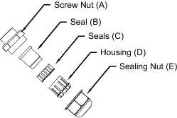
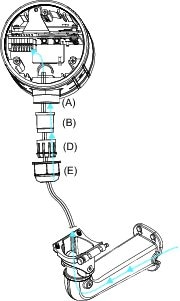
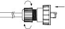
Step 1 ![]() Disassemble the components of the waterproof connector into its individual components as shown below.
Disassemble the components of the waterproof connector into its individual components as shown below.
Step 2 ![]() Remove the back cover from the IP camera.
Remove the back cover from the IP camera.
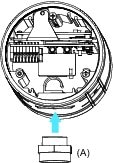
Step 3 ![]() Remove the rubber stopper from the bottom of the IP Camera and tightly secure the screw nut (A).
Remove the rubber stopper from the bottom of the IP Camera and tightly secure the screw nut (A).
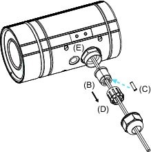
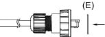
Step 4 ![]() Feed the external power cable and I/O cables through the wall mount bracket and the waterproof connector components (E -> D -> B -> A). Be sure to feed enough cable length through the waterproof connector to connect the cables to the GPIO terminal block.
Feed the external power cable and I/O cables through the wall mount bracket and the waterproof connector components (E -> D -> B -> A). Be sure to feed enough cable length through the waterproof connector to connect the cables to the GPIO terminal block.
Note ![]() There are seven holes on the seal (B), and the widest hole with a crack on the side is specific for the power cable.
There are seven holes on the seal (B), and the widest hole with a crack on the side is specific for the power cable.
The recommended I/O cable gauge is 2.0 ~ 2.8 mm.
Step 5 ![]() Push the seal (B) into the housing (D), and to avoid moisture, insert the seals (C) into the empty holes on the seal (B).
Push the seal (B) into the housing (D), and to avoid moisture, insert the seals (C) into the empty holes on the seal (B).
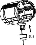
Step 6 ![]() Secure the sealing nut (E) tightly.
Secure the sealing nut (E) tightly.
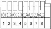
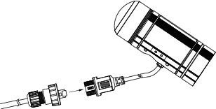
Step 7 ![]() Connect the external power and I/O cables to the GPIO terminal block. The pin locations and descriptions are as follows:
Connect the external power and I/O cables to the GPIO terminal block. The pin locations and descriptions are as follows:
|
|
|
1 |
12 VDC- |
|
2 |
12 VDC+ |
|
3 |
24 VAC |
|
4 |
24 VAC |
|
5 |
DI- |
|
6 |
DI+ |
|
7 |
DO- |
|
8 |
DO+ |
Step 8 ![]() Replace the back cover back onto the camera.
Replace the back cover back onto the camera.
Connecting a Waterproof Ethernet Cable
To connect the 6400 IP camera to an Ethernet cable with a waterproof connection, perform the following steps.
Procedure
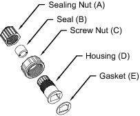
Step 1 ![]() Disassemble the components of the waterproof connector into its individual components as shown below.
Disassemble the components of the waterproof connector into its individual components as shown below.
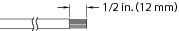
Step 2 ![]() Strip about 1/2 inch (12 mm) of the sheath off the end of an Ethernet cable.
Strip about 1/2 inch (12 mm) of the sheath off the end of an Ethernet cable.
Step 3 ![]() Insert the housing (D) into the screw nut (C).
Insert the housing (D) into the screw nut (C).

Step 4 ![]() Insert the seal (B) into the housing (D).
Insert the seal (B) into the housing (D).

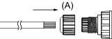
Step 5 ![]() Insert the stripped Ethernet cable through the sealing nut (A) and the housing (D).
Insert the stripped Ethernet cable through the sealing nut (A) and the housing (D).
Step 6 ![]() Clamp the cable with an RJ45 plug.
Clamp the cable with an RJ45 plug.
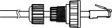
Step 7 ![]() Push the RJ45 plug into the housing (D) and tighten the sealing nut.
Push the RJ45 plug into the housing (D) and tighten the sealing nut.
Step 8 ![]() Attach the gasket to the front surface of the housing (D).
Attach the gasket to the front surface of the housing (D).
Step 9 ![]() Connect the Ethernet cable to the RJ45 jack and tighten the waterproof connector.
Connect the Ethernet cable to the RJ45 jack and tighten the waterproof connector.
Installing the Sun Shield
To install the sun shield, perform the following steps.
Procedure
Step 1 ![]() Attach the two included standoff screws to the top of the 6400 IP camera.
Attach the two included standoff screws to the top of the 6400 IP camera.
Step 2 ![]() Place the sun shield on top of the two standoff screws and slide it backward or forward to the desired position. Ensure that the holes in the top of the standoff screws are visible through the holes in the sun shield.
Place the sun shield on top of the two standoff screws and slide it backward or forward to the desired position. Ensure that the holes in the top of the standoff screws are visible through the holes in the sun shield.
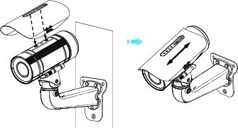
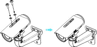
Step 3 ![]() Use the two included screws to secure the sun shield to the two standoff screws.
Use the two included screws to secure the sun shield to the two standoff screws.
 Feedback