- Preface
- Introducing the Sensor
- Preparing the Appliance for Installation
- Installing the IPS 4270-20
- Installing the IPS 4345 and IPS 4360
- Installing the IPS 4510 and IPS 4520
- Installing and Removing the ASA 5500 AIP SSM
- Installing and Removing the ASA 5585-X IPS SSP
- Logging In to the Sensor
- Initializing the Sensor
- Obtaining Software
- Upgrading, Downgrading, and Installing System Images
- Troubleshooting
- Cable Pinouts
- Glossary
- hwguide71IX
Cisco Intrusion Prevention System Appliance and Module Installation Guide for IPS 7.1
Bias-Free Language
The documentation set for this product strives to use bias-free language. For the purposes of this documentation set, bias-free is defined as language that does not imply discrimination based on age, disability, gender, racial identity, ethnic identity, sexual orientation, socioeconomic status, and intersectionality. Exceptions may be present in the documentation due to language that is hardcoded in the user interfaces of the product software, language used based on RFP documentation, or language that is used by a referenced third-party product. Learn more about how Cisco is using Inclusive Language.
- Updated:
- December 9, 2011
Chapter: Installing and Removing the ASA 5585-X IPS SSP
- Contents
- Installation Notes and Caveats
- Introducing the ASA 5585-X IPSSSP
- Specifications
- Hardware and Software Requirements
- Front Panel Features
- Memory Requirements
- SFP/SFP+ Modules
- Installing the ASA 5585-X IPS SSP
- Installing SFP/SFP+ Modules
- Verifying the Status of the ASA 5585-X IPS SSP
- Removing and Replacing the ASA 5585-X IPS SSP
Installing and Removing the ASA 5585-X IPS SSP
Contents
This chapter describes the Cisco ASA 5585-X IPS SSP, and contains the following sections:
- Installation Notes and Caveats
- Introducing the ASA 5585-X IPS SSP
- Specifications
- Hardware and Software Requirements
- Front Panel Features
- Memory Requirements
- SFP/SFP+ Modules
- Installing the ASA 5585-X IPS SSP
- Installing SFP/SFP+ Modules
- Verifying the Status of the ASA 5585-X IPS SSP
- Removing and Replacing the ASA 5585-X IPS SSP

Warning Only trained and qualified personnel should install, replace, or service this equipment. Statement 49
Installation Notes and Caveats
Pay attention to the following installation notes and caveats before installing the ASA 5585-X IPS SSP:
- Read the safety warnings in the Regulatory Compliance and Safety Information for the Cisco ASA 5585-X Adaptive Security Appliance document and follow proper safety procedures when performing the steps in this guide.
- The ASA 5585-X IPS SSP is supported in ASA 8.2(4.4) and later as well as ASA 8.4(2) and later. It is not supported in ASA 8.3( x ).
- The ASA 5585-X IPS SSP does not require any cabling. If you have an ASA 5585-X IPS SSP, you can use the ASA 5585-X IPS SSP nonmanagement interfaces as additional network interfaces.
- Read through the entire guide before beginning any of the installation procedures.
Introducing the ASA 5585-X IPS SSP
You can install the Cisco Intrusion Prevention System Security Services Processor (ASA 5585-X IPS SSP) in the ASA-5585-X adaptive security appliance. The ASA 5585-X is a 2RU, two-slot chassis. The Security Services Processor (ASA 5585-X SSP) resides in slot 0 (the bottom slot) and the ASA 5585-X IPS SSP resides in slot 1 (the top slot). All port numbers are numbered from right to left beginning with 0.
The ASA 5585-X series with the IPS SSP comes in four models:
- ASA 5585-X IPS-10 with IPS SSP-10
- ASA 5585-X IPS-20 with IPS SSP-20
- ASA 5585-X IPS-40 with IPS SSP-40
- ASA 5585-X IPS-60 with IPS SSP-60
In addition to world-class performance, the ASA 5585-X deploys encrypted traffic inspection, port density (up to 20 interfaces depending on the model), and feature performance matching, that is, performance parity between firewall and IPS functions. All ASA 5585-X series adaptive security appliances ship with a core SSP (ASA 5585-X SSP); the ASA 5585-X IPS SSP is optional. You must have the core SSP to run the ASA 5585-X IPS SSP.

Note![]() Online insertion and removal (OIR) of the security services processors is not supported at this time. SFP/SFP+, power supply module, and fan module OIR is supported.
Online insertion and removal (OIR) of the security services processors is not supported at this time. SFP/SFP+, power supply module, and fan module OIR is supported.
The ASA 5585-X IPS SSP supports the Intrusion Prevention System Device Manager (IDM) 7.1. The IDM delivers security management and monitoring through an intuitive, easy-to-use web-based management interface. The IDM is a Java Web Start application that enables you to configure and manage your ASA 5585-X IPS SSP. The IDM is bundled with IPS 7.1. You can access it through Internet Explorer or Firefox web browsers.
The Intrusion Prevention System Manager Express (IME) 7.1 also supports the ASA 5585-X IPS SSP. The IME is a network management application that provides system health, events, and collaboration monitoring in addition to reporting and configuration for up to ten sensors. The IME monitors sensor health using customizable dashboards and provides security alerts through RSS feed integration from the Cisco Security Intelligence Operations site. It monitors global correlation data, which you can view in events and reports. It monitors events and lets you sort views by filtering, grouping, and colorization. The IME also supports tools such as ping, trace route, DNS lookup, and whois lookup for selected events. It contains a flexible reporting network. It embeds the IDM configuration component to allow for a seamless integration between the monitoring and configuration of IPS devices. Within the IME you can set up your sensors, configure policies, monitor IPS events, and generate reports. The IME works in single application mode—the entire application is installed on one system and you manage everything from that system.
ASA 5585-X SSP-10 With IPS SSP-10
The ASA 5585-X SSP-10 with IPS SSP-10 provides firewall, VPN support, intrusion prevention system protection, and 20 interfaces (2 SFP/SFP+ and 18 copper Gigabit Ethernet). The SSP-10 with IPS SSP-10 has one power supply module and one fan module. You can replace the fan module with another power supply module for a redundant power supply configuration. The SSP-10 with IPS SSP-10 has two CPUs, six DIMM modules, two embedded crypto accelerator, and two dual-port 10-GB uplinks for the SFP/SFP+ interfaces.
ASA 5585-X SSP-20 With IPS SSP-20
The ASA 5585-X SSP-20 with IPS SSP-20 provides firewall, VPN support, intrusion prevention system protection, and 20 interfaces (2 SFP/SFP+ and 18 copper Gigabit Ethernet). The SSP-20 with IPS SSP-20 has one power supply module and one fan module. You can replace the fan module with another power supply module for a redundant power supply configuration. The SSP-20 with IPS SSP-20 has two CPUs, 12 DIMM modules, four embedded crypto accelerators, and two dual-port 10-GB uplinks for the SFP/SFP+ interfaces.
ASA 5585-X SSP-40 With IPS SSP-40
The ASA 5585-X SSP-40 with IPS SSP-40 provides firewall, VPN support, intrusion prevention system protection, and 20 interfaces (4 SFP/SFP+ and 16 copper Gigabit Ethernet). The SSP-40 with IPS SSP-40 has one power supply module and one fan module. You can replace the fan module with another power supply module for a redundant power supply configuration. The SSP-40 with IPS SSP-40 has four CPUs, 12 DIMM modules, six embedded crypto accelerators, and four dual-port 10-GB uplinks for the SFP/SFP+ interfaces.
ASA 5585-X SSP-60 With IPS SSP-60
The ASA 5585-X SSP-60 with IPS SSP-60 provides firewall, VPN support, intrusion prevention system protection, and 20 interfaces (4 SFP/SFP+ and 16 copper Gigabit Ethernet). The SSP-60 with IPS SSP-60 ships with two power supply modules; however, the SSP-60 with IPS SSP-60 can function with only one power supply module. Although the SSP-60 with IPS SSP-60 can also operate with only one power supply module, we recommend that you install two power supply modules for extended reliability since the power supply modules operate in load-sharing mode. If one fails in this configuration, the other power supply module can still handle the full load until the failed power supply module is replaced. The SSP-60 with IPS SSP-60 has four CPUs, 24 DIMM modules, eight embedded crypto accelerators, and four dual-port 10-GB uplinks for the SFP/SFP+ interfaces.

Specifications
Table 7-1 lists the specifications for the ASA 5585-X IPS SSP.
Operating 32 to 104°F (0 to 40°C) |
|
Hardware and Software Requirements
The ASA 5585-X IPS SSP has the following hardware and software requirements:
–![]() ASA 5585-X SSP-10 with IPS SSP-10
ASA 5585-X SSP-10 with IPS SSP-10
–![]() ASA 5585-X SSP-20 with IPS SSP-20
ASA 5585-X SSP-20 with IPS SSP-20
–![]() ASA 5585-X SSP-40 with IPS SSP-40
ASA 5585-X SSP-40 with IPS SSP-40
–![]() ASA 5585-X SSP-60 with IPS SSP-60
ASA 5585-X SSP-60 with IPS SSP-60
- Cisco Adaptive Security Appliance Software ASA 8.2(4.4) and later
- Cisco Adaptive Security Appliance Software ASA 8.4(2) and later
Note The ASA 5585-X IPS SSP is not supported in ASA 8.3(x).
Front Panel Features
This section describes the front features and indicators of the ASA 5585-X IPS SSP. The SFP and SFP+ modules are optional and not included with the ASA 5585-X IPS SSP. You can purchase them separately. For 10 Gb, you need SFP+. For 1 Gb, you need SFP. The two ports are the same, but you can only use 10 Gb if you buy a license. Otherwise, the ports are restricted to 1 Gb. The ports are always 10 GB-enabled for the IPS SSP-40 and IPS SSP-60. The interfaces are called TenGigabitEthernet 1/ x whether they are 10 GB-enabled or not.
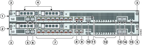
Figure 7-1 shows the front view of the IPS SSP-10 and IPS SSP-20.
Note![]() The illustration shows IPS SSP-10, but it applies to both the -10 and -20 models.
The illustration shows IPS SSP-10, but it applies to both the -10 and -20 models.
Figure 7-1 IPS SSP-10 Front Panel View
|
|
|
||
|
|
|
||
|
|
|
||
|
|
Reserved bays for hard disk drives1 |
|
|
|
|
|
||
|
|
|
||
|
|
GigabitEthernet 1/0 through 1/7, from right to left (1-Gb copper, RJ45) |
|
Eject2 |
|
|
|
|
1.Hard disk drives are not supported at this time. The hard disk drive bays are empty. |
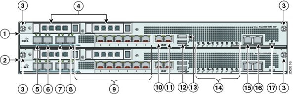
Figure 7-2 shows the front view of IPS SSP-40 and IPS SSP-60.
Note![]() The illustration shows IPS SSP-40, but it applies to both the -40 and the -60 models.
The illustration shows IPS SSP-40, but it applies to both the -40 and the -60 models.
Figure 7-2 IPS SSP-40 Front Panel View
|
|
|
||
|
|
|
||
|
|
|
||
|
|
Reserved bays for hard disk drives3 |
|
|
|
|
|
||
|
|
|
||
|
|
|
||
|
|
TenGigabitEthernet 0/6 (SSP in slot 2) |
|
Eject4 |
|
|
GigabitEthernet 0/0 through 0/5 (SSP in slot 2) |
|
|
3.Hard disk drives are not supported at this time. The hard disk drive bays are empty. |
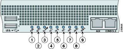
Figure 7-3 shows the front panel indicators.
Figure 7-3 ASA 5585-X IPS SSP Front Panel Indicators
|
|
|
||
|
|
|
||
|
|
|
||
|
|
|
||
|
|
|
Table 7-2 describes the front panel indicators on the ASA 5585-X IPS SSP.
|
|
|
|---|---|
ALARM5 |
Indicates whether a component has failed: Major failure of hardware component or software module, temperature over the limit, power out of tolerance, or OIR is ready to remove the module.6. |
Indicates the state of the power supply module installed on the right when facing the back panel: |
|
Indicates the state of the power module installed on the left when facing the back panel: |
|
|
|
|
|
|
|
5.The Cisco ASA software does not support the ALARM indicator initially; support will be added at a later date. |
Table 7-3 shows the Ethernet port indicators.
|
|
|
|---|---|
10-Gigabit Ethernet Fiber (SFP+)/1-Gigabit Ethernet Fiber (SFP) |
– – – – |
|
7.Flashing green is in proportion to the percentage of number of packets or bytes received. |
Memory Requirements
The ASA-5585-X has up to 6 DIMM modules per CPU. DIMM population is platform-dependent as seen in the following memory configurations:
SFP/SFP+ Modules
The SFP/SFP+ module is a hot-swappable input/output device that plugs into the SFP/SFP+ ports and provides Gigabit Ethernet connectivity. The SFP and SFP+ modules are optional and not included with the ASA 5585-X IPS SSP. You can purchase them separately. For 1 Gb, you need SFP. For 10Gb, you need SFP+. The interfaces are called TenGigabitEthernet 0/ x whether they are 10 Gb-enabled or not.
Table 7-4 lists the SFP/SFP+ modules that the ASA 5585-X IPS SSP supports.
|
|
|
|---|---|
|
|
|
Installing the ASA 5585-X IPS SSP
The ASA 5585-X comes with a core SSP already installed (SSP-10, SSP-20, SSP-40, or SSP-60). You can install an optional ASA 5585-X IPS SSP (IPS SSP-10, IPS SSP-20, IPS SSP-40, or IPS SSP-60).
Note![]() The ASA 5585-X IPS SSP must be at the same level as the ASA 5585-X SSP model; for example, if you have the ASA 5585-X with SSP-10, you can only install the IPS SSP-10.
The ASA 5585-X IPS SSP must be at the same level as the ASA 5585-X SSP model; for example, if you have the ASA 5585-X with SSP-10, you can only install the IPS SSP-10.
The ASA 5585-X IPS SSP will not run without the core SSP installed. You must install the ASA 5585-X IPS SSP in the upper slot (slot 1) and the core SSP in the bottom slot (slot 0). You must power off the ASA 5585-X to remove and install SSPs. The SSPs are not hot-swappable.
To install the ASA 5585-X IPS SSP in the ASA 5585-X for the first time, follow these steps:
Step 1![]() Power off the ASA 5585-X.
Power off the ASA 5585-X.
Step 2![]() Remove the power cable from the ASA 5585-X.
Remove the power cable from the ASA 5585-X.
Step 3![]() From the front panel of the ASA 5585-X, loosen the captive screws on the upper left and right of the slot tray (slot 1), and remove it. Store it in a safe place for future use.
From the front panel of the ASA 5585-X, loosen the captive screws on the upper left and right of the slot tray (slot 1), and remove it. Store it in a safe place for future use.
Note You must install slot trays in all empty slots to maintain the proper air flow. This prevents EMI, which can disrupt other equipment.
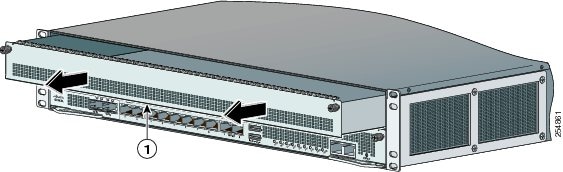
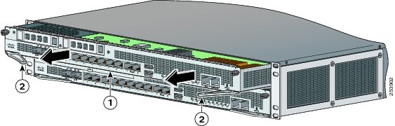
Step 4![]() Install the ASA 5585-X IPS SSP by lining it up with the module slot making sure the ejection levers are extended.
Install the ASA 5585-X IPS SSP by lining it up with the module slot making sure the ejection levers are extended.

|
|
|
Step 5![]() Slide the ASA 5585-X IPS SSP in to the slot until it is seated and push the ejection levers back in to place.
Slide the ASA 5585-X IPS SSP in to the slot until it is seated and push the ejection levers back in to place.
Step 7![]() Reconnect the power cable to the ASA 5585-X.
Reconnect the power cable to the ASA 5585-X.
Step 8![]() Power on the ASA 5585-X.
Power on the ASA 5585-X.
Step 9![]() Verify that the PWR indicator on the front panel is green. You can also verify that the ASA 5585-X IPS SSP is online using the show module 1 command.
Verify that the PWR indicator on the front panel is green. You can also verify that the ASA 5585-X IPS SSP is online using the show module 1 command.
Step 10![]() Initialize the ASA 5585-X IPS SSP.
Initialize the ASA 5585-X IPS SSP.
Step 11![]() Configure the ASA 5585-X IPS SSP to receive IPS traffic.
Configure the ASA 5585-X IPS SSP to receive IPS traffic.
- For more information about ESD, see Preventing Electrostatic Discharge Damage.
- For the procedure for verifying that the ASA 5585-X IPS SSP is properly installed, see Verifying the Status of the ASA 5585-X IPS SSP.
- For the procedure for using the setup command to initialize the ASA 5585-X IPS SSP, see Appendix B, “Initializing the Sensor.”
- For the procedure for configuring the ASA 5585-X IPS SSP to receive IPS traffic, refer to Configuring the ASA 5585-X IPS SSP .
- For detailed information about the ASA 5585-X, refer to Cisco ASA 5585-X Adaptive Security Appliance Hardware Installation Guide .
Installing SFP/SFP+ Modules
The IPS SSP-10 and IPS SSP-20 have two SFP/SFP+ ports. The IPS SSP-40 and IPS SSP-60 have four SFP/SFP+ ports. If you are using the fiber ports, you need an SFP+ module for 10-Gigabit Ethernet (a license may be required) or an SFP module for 1-Gigabit Ethernet (SFP or SFP+ modules are not included).
Note![]() Make sure the ASA software version that is installed on your ASA 5585-X supports the network module. Refer to the Release Notes for your ASA software version to verify that the network module is supported.
Make sure the ASA software version that is installed on your ASA 5585-X supports the network module. Refer to the Release Notes for your ASA software version to verify that the network module is supported.
Note![]() Only SFP/SFP+ modules certified by Cisco are supported on the adaptive security appliance 5585-X.
Only SFP/SFP+ modules certified by Cisco are supported on the adaptive security appliance 5585-X.
Warning Because invisible laser radiation may be emitted from the aperture of the port when no cable is connected, avoid exposure to laser radiation and do not stare into open apertures. Statement 70
To connect to the SFP/SFP+ port if you are using fiber ports, follow these steps:
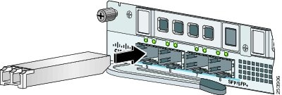
Step 2![]() Connect one end of the LC cable to the SFP/SFP+.
Connect one end of the LC cable to the SFP/SFP+.
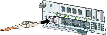
Step 3![]() Connect the other end of the LC cable to a network device, such as a router or switch.
Connect the other end of the LC cable to a network device, such as a router or switch.
For a table listing the supported SFP/SFP+ modules, see SFP/SFP+ Modules.
Verifying the Status of the ASA 5585-X IPS SSP
You can use the show module 1 command to verify that the ASA 5585-X IPS SSP is up and running.
The following values are valid for the Status field:
-
Initializing—The ASA 5585-X IPS SSP is being detected and the control communication is being initialized by the system. -
Up—The ASA 5585-X IPS SSP has completed initialization by the system. -
Unresponsive—The system encountered an error communicating with the ASA 5585-X IPS SSP. -
Reloading—The ASA 5585-X IPS SSP is reloading. -
Shutting Down—The ASA 5585-X IPS SSP is shutting down. -
Down—The ASA 5585-X IPS SSP is shut down. -
Recover—The ASA 5585-X IPS SSP is attempting to download a recovery image.
To verify the status of the ASA 5585-X IPS SSP, follow these steps:
Step 2![]() Verify the status of the ASA 5585-X IPS SSP:
Verify the status of the ASA 5585-X IPS SSP:
If the status reads Up , the ASA 5585-X IPS SSP has been properly installed.
Removing and Replacing the ASA 5585-X IPS SSP
To remove and replace the ASA 5585-X IPS SSP in the ASA 5585-X, follow these steps:
Step 2![]() Press Enter to confirm.
Press Enter to confirm.
Step 3![]() Verify that the ASA 5585-X IPS SSP is shut down by checking the indicators.
Verify that the ASA 5585-X IPS SSP is shut down by checking the indicators.
Step 4![]() Power off the ASA 5585-X.
Power off the ASA 5585-X.
Step 5![]() Remove the power cable from the ASA 5585-X.
Remove the power cable from the ASA 5585-X.
Step 6![]() From the front panel of the ASA 5585-X, loosen the captive screws on the upper left and right of the ASA 5585-X IPS SSP in slot 1.
From the front panel of the ASA 5585-X, loosen the captive screws on the upper left and right of the ASA 5585-X IPS SSP in slot 1.
Step 7![]() Grasp the ejection levers at the left and right bottom of the module slot and pull them out.
Grasp the ejection levers at the left and right bottom of the module slot and pull them out.
|
|
|
Step 8![]() Grasp the sides of the ASA 5585-X IPS SSP and pull it all the way out of the chassis and set it aside.
Grasp the sides of the ASA 5585-X IPS SSP and pull it all the way out of the chassis and set it aside.
Note If you are not replacing the ASA 5585-X IPS SSP immediately, install the blank slot tray. You must install slot trays in all empty slots to maintain the proper air flow. This prevents EMI, which can disrupt other equipment.
Step 9![]() If you are replacing the ASA 5585-X IPS SSP, install it by lining it up with the module slot making sure the ejection levers are extended.
If you are replacing the ASA 5585-X IPS SSP, install it by lining it up with the module slot making sure the ejection levers are extended.
|
|
|
Note The ASA 5585-X IPS SSP must be at the same level as the ASA 5585-X SSP model; for example, if you have the ASA 5585-X SSP-10, you can only install the ASA 5585-X IPS SSP-10.
Step 10![]() Slide the ASA 5585-X IPS SSP in to the slot until it is seated, and push the ejection levers back in to place.
Slide the ASA 5585-X IPS SSP in to the slot until it is seated, and push the ejection levers back in to place.
Step 12![]() Reconnect the power cable to the ASA 5585-X.
Reconnect the power cable to the ASA 5585-X.
Step 13![]() Power on the ASA 5585-X.
Power on the ASA 5585-X.
Step 14![]() Verify that the PWR indicator on the front panel is green. You can also verify that the ASA 5585-X IPS SSP is online using the show module 1 command.
Verify that the PWR indicator on the front panel is green. You can also verify that the ASA 5585-X IPS SSP is online using the show module 1 command.
- For the procedure for using the show module 1 command, see Verifying the Status of the ASA 5585-X IPS SSP.
- For detailed information about the ASA 5585-X, refer to Cisco ASA 5585-X Adaptive Security Appliance Hardware Installation Guide .
 Feedback