- Preface
- New and Changed Information in Release 4.3.x
- Implementing MPLS Layer 2 VPNs
- Implementing Virtual Private LAN Services
- Implementing IPv6 VPN Provider Edge Transport over MPLS
- Implementing Layer 2 Tunnel Protocol Version 3
- Implementing MPLS VPNs over IP Tunnels
- Implementing MPLS Layer 3 VPNs
- Index
Cisco IOS XR Virtual Private Network Configuration Guide for the Cisco XR 12000 Series Router, Release 4.3.x
Bias-Free Language
The documentation set for this product strives to use bias-free language. For the purposes of this documentation set, bias-free is defined as language that does not imply discrimination based on age, disability, gender, racial identity, ethnic identity, sexual orientation, socioeconomic status, and intersectionality. Exceptions may be present in the documentation due to language that is hardcoded in the user interfaces of the product software, language used based on RFP documentation, or language that is used by a referenced third-party product. Learn more about how Cisco is using Inclusive Language.
- Updated:
- December 20, 2012
Chapter: Implementing Layer 2 Tunnel Protocol Version 3
- Contents
- Prerequisites for Layer 2 Tunnel Protocol Version 3
- Information About Layer 2 Tunnel Protocol Version 3
- L2TPv3 Operation
- L2TPv3 Benefits
- L2TPv3 Features
- Static L2TPv3 Sessions
- Dynamic L2TPv3 Sessions
- Sequencing
- Local Switching
- Local Switching: Quality of Service
- L2TPv3 Pseudowire Switching
- L2TPv3 Pseudowire Manager
- IP Packet Fragmentation
- L2TPv3 Type of Service Marking
- Keepalive
- Maximum Transmission Unit Handling
- L2TPV3 IP Interworking
- Like-to-Like Pseudowires
Implementing Layer 2 Tunnel Protocol Version 3
Layer 2 Tunnel Protocol Version 3 (L2TPv3) is an Internet Engineering Task Force (IETF) working group draft that provides several enhancements to L2TP, including the ability to tunnel any Layer 2 (L2) payload over L2TP. Specifically, L2TPv3 defines the L2TP protocol for tunneling Layer 2 payloads over an IP core network using L2 virtual private networks (VPNs).
For additional information about L2TPv3, see MPLS VPNs over IP Tunnels on Cisco IOS XR Software.
Feature History for Implementing Layer 2 Tunnel Protocol Version 3 on Cisco IOS XR
Contents
Prerequisites for Layer 2 Tunnel Protocol Version 3
The following prerequisites are required to implement L2TPv3:
- To perform these configuration tasks, your Cisco IOS XR software system administrator must assign you to a user group associated with a task group that includes the corresponding command task IDs. All command task IDs are listed in individual command references and in the Cisco IOS XR Task ID Reference Guide.
If you need assistance with your task group assignment, contact your system administrator.
- You must enable Cisco Express Forwarding (CEF) before you configure a cross-connect attachment circuit (AC) for a customer edge (CE) device.
- You must configure a Loopback interface on the router for originating and terminating the L2TPv3 traffic. The Loopback interface must have an IP address that is reachable from the remote provider edge (PE) device at the other end of an L2TPv3 control-channel.
- You must enable Simple Network Management Protocol (SNMP) notifications of L2TP session up and session down events.

Note![]() A cross-connection is expressed as xconnect in the CLI.
A cross-connection is expressed as xconnect in the CLI.
Information About Layer 2 Tunnel Protocol Version 3
To configure the L2TPv3 feature, you should understand the following concepts:
L2TPv3 Operation
Figure 22 shows how the L2TPv3 feature is used to set up VPNs using Layer 2 tunneling over an IP network. All traffic between two customer network sites is encapsulated in IP packets carrying L2TP data messages and sent across an IP network. The backbone routers of the IP network treat the traffic as any other IP traffic and needn’t know anything about the customer networks.
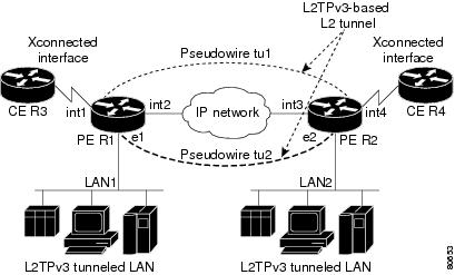
In , the PE routers R1 and R2 provide L2TPv3 services. The R1 and R2 routers communicate with each other using a pseudowire over the IP backbone network through a path comprising the interfaces int1 and int2, the IP network, and interfaces int3 and int4. The CE routers R3 and R4 communicate through a pair of cross-connected Ethernet or 802.1q VLAN interfaces using an L2TPv3 session. The L2TPv3 session tu1 is a pseudowire configured between interface int1 on R1 and interface int4 on R2. Any packet arriving on interface int1 on R1 is encapsulated and sent through the pseudowire control-channel (tu1) to R2. R2 decapsulates the packet and sends it on interface int4 to R4. When R4 needs to send a packet to R3, the packet follows the same path in reverse.
L2TPv3 Benefits
L2TPv3 provides the following benefits:
- Simplifies deployment of VPNs—L2TPv3 is an industry-standard L2 tunneling protocol that ensures interoperability among vendors, increasing customer flexibility and service availability.
- Does not require MPLS—Service providers need not deploy MPLS in the core IP backbone to set up VPNs using L2TPv3 over the IP backbone; this will result in operational savings and increased revenue.
- Supports L2 tunneling over IP for any payload—L2TPv3 provides enhancements to L2TP to support L2 tunneling of any payload over an IP core network. L2TPv3 defines the base L2TP protocol as being separate from the L2 payload that is tunneled.
L2TPv3 Features
L2TPv3 provides cross-connect support for Ethernet, 802.1q (VLAN), Frame Relay, HDLC, and PPP, and ATM using the sessions described in the following sections:
- Sequencing
- Local Switching
- Local Switching: Quality of Service
- L2TPv3 Pseudowire Switching
- L2TPv3 Pseudowire Manager
- IP Packet Fragmentation
- L2TPv3 Type of Service Marking
- Keepalive
- Maximum Transmission Unit Handling
- Distributed switching
- L2TPv3 L2 fragmentation
- L2TPv3 control message hashing
- L2TPv3 control message rate limiting
- L2TPv3 digest secret graceful switchover
- Manual clearing of L2TPv3 tunnels
- L2TPv3 tunnel management
- Color aware policer on ethernet over L2TPv3
- Site of origin for BGP VPNs
- L2TPV3 IP Interworking
- Like-to-Like Pseudowires
Static L2TPv3 Sessions
Typically, the L2TP control plane is responsible for negotiating session parameters (such as the session ID or the cookie) to set up the session; however, some IP networks require sessions to be configured so that no signaling is required for session establishment. Therefore, you can set up static L2TPv3 sessions for a PE router by configuring fixed values for the fields in the L2TP data header. A static L2TPv3 session allows the PE to tunnel L2 traffic as soon as the AC to which the session is bound comes up.
Note![]() In an L2TPv3 static session, you can still run the L2TP control-channel to perform peer authentication and dead-peer detection. If the L2TP control-channel cannot be established or is torn down because of a hello failure, the static session is also torn down.
In an L2TPv3 static session, you can still run the L2TP control-channel to perform peer authentication and dead-peer detection. If the L2TP control-channel cannot be established or is torn down because of a hello failure, the static session is also torn down.
When you use a static L2TPv3 session, you cannot perform circuit interworking (for example, LMI) because there is no facility to exchange control messages. To perform circuit interworking, you must use a dynamic session.
Dynamic L2TPv3 Sessions
A dynamic L2TP session is established through the exchange of control messages containing attribute-value pair (AVP). Each AVP contains information about the nature of the L2 link being forwarded: including the payload type, virtual circuit (VC) ID, and so on.
Multiple L2TP sessions can exist between a pair of PEs, and can be maintained by a single control-channel. Session IDs and cookies are dynamically generated and exchanged as part of a dynamic session setup. Sequencing configuration is also exchanged and circuit state changes are conveyed using the set link info (SLI) message.
Sequencing
Although the correct sequence of received L2 frames is guaranteed by some L2 technologies (by the nature of the link, such as a serial line) or the protocol itself, forwarded L2 frames may be lost, duplicated, or reordered when they traverse a network as IP packets. If the L2 protocol does not provide an explicit sequencing mechanism, you can configure L2TP to sequence its data packets according to the data channel sequencing mechanism described in the L2TPv3 IETF l2tpext working group draft.
A receiver of L2TP data packets mandates sequencing through the sequencing required AVP when the session is being negotiated. A sender that receives this AVP (or that is manually configured to send sequenced packets) uses the L2-specific pseudowire control encapsulation defined in L2TPv3.
Currently, you can configure L2TP only to drop out-of-order packets; you cannot configure L2TP to deliver the packets out-of-order. No reordering mechanism is available.
Local Switching
An AC to AC cross-connect, also called local switching, is a building block of L2VPN that allows frames to switch between two different ACs on the same PE. PE (see Figure 23).
You must configure separate IP addresses for each cross-connect statement on the Carrier Edge router.
The following configurations are supported for local switching:
- IP interworking for Ethernet, Frame Relay and ATM.
- Like-to-like Pseudowires for point-to-point connections, High-Level Data Link Control (HDLC), and Ethernet, and Frame Relay.
- VLAN-to-VLAN
- Port-to-VLAN
- VLAN-to-Port
- Encapsulation-to-other end encapsulation
- Port-to-Port
- Dot1q-to-Dot1q
- QinQ-to-QinQ
- QinAny-to-QinAny
- Dot1q-to-QinQ
- QinQ-to-Dot1q
- QinQ-to-QinAny
- QinAny-to-QinQ
Note![]() VLAN-to-VLAN options do not require interworking. Port-to-VLAN and VLAN-to-port do, and it is locally managed by the L2VPN application. If both interfaces are Ethernet VLAN, each reside on a single physical interface. By definition, local switching is not a pseudowire technology, because signaling protocols (such as LDP or L2TPv3) are not involved.
VLAN-to-VLAN options do not require interworking. Port-to-VLAN and VLAN-to-port do, and it is locally managed by the L2VPN application. If both interfaces are Ethernet VLAN, each reside on a single physical interface. By definition, local switching is not a pseudowire technology, because signaling protocols (such as LDP or L2TPv3) are not involved.
Note![]() In Release 4.0, the QinQ or QinAny over L2TPv3 feature is supported only on the Engine 5 V2 SPAs. The Engine 3 line cards do not support this feature.
In Release 4.0, the QinQ or QinAny over L2TPv3 feature is supported only on the Engine 5 V2 SPAs. The Engine 3 line cards do not support this feature.
Figure 23 Local Switching Operation

Local Switching: Quality of Service
The following quality of service (QoS) requirements apply to local switching:
- QoS service policies can be applied to any L2 AC (port or VLAN, or both) and can be applied to any interworking mode (port-to-port, vlan-to-port, port-to-vlan, vlan-to-vlan). The AC can be cross-connected to a pseudowire (EoL2TPv3) or to another AC (local switching).
- QoS service policies can be attached directly to the AC.
- QoS service policies can be attached to the main interface using match vlan on L2 VLAN ACs.
- QoS service policies attached to the main interface can be inherited by all L2 VLANs.
- QoS service policies cannot be attached to a main interface when there are service policies already attached to its L3VLANs or L2VLAN ACs.
- QoS service policies already attached to the main interface are not permitted on L3 VLAN or L2 VLAN ACs.
L2TPv3 Pseudowire Switching
L2VPN pseudowire switching allows you to:
- Extend L2VPN pseudowires across an Inter-AS boundary.
- Connect two or more contiguous pseudowire segments to form an end-to-end multihop pseudowire.
- Keep the IP addresses of the edge PE routers private across Inter-AS boundaries.
- Keep different administrative or provisioning domains to manage the end-to-end service.
L2TPv3 Pseudowire Manager
The pseudowire manager is a client library provided by the pseudowire signaling module that runs in the context of the L2VPN process. This client library implements interface to pseudo-wire signaling protocol for specific pseudowire type.
IP Packet Fragmentation
It is desirable to avoid fragmentation issues in the service provider network because reassembly is computationally expensive. The easiest way to avoid fragmentation issues is to configure the CE routers with an Maximum Transmission Unit (MTU) value that is smaller than the pseudowire path MTU. However, in scenarios where this is not an option, fragmentation issues must be considered. Previously, L2TP supported only the following options for packet fragmentation when a packet is determined to exceed the L2TP path MTU:
- Unconditionally drop the packet
- Fragment the packet after L2TP/IP encapsulation
- Drop the packet and send an Internet Control Message Protocol (ICMP) unreachable message back to the CE router
Currently, the following options for packet fragmentation are supported:
- Path MTU is a configurable value which is configured on PE. If the packet size and the L2TP header size are larger than the configured path MTU, packets are dropped.
- The PE configuration requires that a backbone facing interface's MTU is always greater or equal to the customer facing interface’s MTU and L2TP header size.
- IP fragmentation is not supported with L2TPv3.
L2TPv3 Type of Service Marking
When L2 traffic is tunneled across an IP network, information contained in the type of service (ToS) bits may be transferred to the L2TP-encapsulated IP packets in one of the following ways:
- If the tunneled L2 frames encapsulate IP packets themselves, it may be desirable to simply copy the ToS bytes of the inner IP packets to the outer IP packet headers. This action is known as “ToS byte reflection.”
- Static ToS byte configuration. You specify the ToS byte value used by all packets sent across the pseudowire.
Keepalive
The keepalive mechanism for L2TPv3 extends only to the endpoints of the tunneling protocol. L2TP has a reliable control message delivery mechanism that serves as the basis for the keepalive mechanism. The keepalive mechanism consists of an exchange of L2TP hello messages.
If a keepalive mechanism is required, the control plane is used, although it may not be used to bring up sessions. You can manually configure sessions.
In the case of static L2TPv3 sessions, a control channel between the two L2TP peers is negotiated through the exchange of start control channel request (SCCRQ), start control channel replay (SCCRP), and start control channel connected (SCCCN) control messages. The control channel is responsible only for maintaining the keepalive mechanism through the exchange of hello messages.
The interval between hello messages is configurable per control channel. If one peer detects that the other has gone down through the keepalive mechanism, it sends a StopCCN control message and then notifies all of the pseudowires to the peer about the event. This notification results in the teardown of both manually configured and dynamic sessions.
Maximum Transmission Unit Handling
It is important that you configure an maximum transmission unit (MTU) appropriate for a each L2TPv3 tunneled link. The configured MTU size ensures that the lengths of the tunneled L2 frames fall below the MTU of the destination AC.
L2TPV3 IP Interworking
IP Interworking, also known as routed interworking, is a way in which diverse transports are interconnected to each other over a Layer 2 transport such as L2TPv3. For example, a Frame Relay DLCI could be connected at one end to an Ethernet VLAN at the other. This kind of interconnection is normal for Layer 3 connections where the Layer 2 encapsulation is disregarded and only the inner Layer 3 packet is transported over the network. IP Interworking performs the same function, except that it does not route based on the Layer 3 IP address. Instead, it uses a fixed point-to-point connection per session based on user configuration, and signaled by the L2TPv3 control plane.
The prerequisite to IP Interworking is that the payload being transported over a pseudowire is an IP payload. Non-IP packets are not transported over the pseudowire.
The following modes support interworking in L2TPv3 on the Engine-5 line cards:
Ethernet Port Mode and VLAN mode
In the Ethernet Port mode, the Ethernet header is removed during encapsulation and only the inner IP packet is encapsulated with L2TPv3 headers and sent across the pseudowire. Only non-broadcast mode is supported and only one MAC address is associated with a single VLAN. If the Q-in-Q mode is not supported, then those frames are dropped.
During decapsulation, the L2TPv3 headers are removed and the appropriate ethernet header is placed before the IP packet and this is transmitted to the customer edge router. A broadcast address is used until the correct MAC address is identified. The Provider Edge router sends Internet Router Discovery Protocol (IRDP) messages over the ethernet link to get the MAC address from the Customer Edge router. The CE must be configured to receive and respond to IRDP.
Frame Relay Point-to-Point DLCI and MLFR
In the Frame Relay DLCI mode of IP interworking, the Frame Relay header is removed during encapsulation and only the inner IP packet is encapsulated with L2TPv3 headers and sent across the pseudowire. During decapsulation, the L2TPv3 headers are removed and the Frame Relay header and DLCI are placed before the IP packet. This is transmitted to the customer edge router.
ATM (AAL5)
IP interworking for ATM in L2TPv3 is supported only in the ATM adaptation layer 5 (AAL5) mode as this mode supports IP packets as payload, and these packets can be extracted. In other modes such as cell relay modes, there is no standard to identify the IP payload.
For IP interworking in ATM, the ATM headers are removed during encapsulation and only the inner IP packet is encapsulated with L2TPv3 headers and transported across the pseudowire.
Note![]() A Layer 2 header is not transported over the pseudowire from the remote end. It must be manually added during decapsulation. LMI or other control frames arealso not carried from the remote end, therefore these cannot be sent out as decapsulated packets.
A Layer 2 header is not transported over the pseudowire from the remote end. It must be manually added during decapsulation. LMI or other control frames arealso not carried from the remote end, therefore these cannot be sent out as decapsulated packets.
Like-to-Like Pseudowires
A PseudoWire (PW) is a bidirectional virtual circuit (VC) connecting two Attached Circuits (ACs). In an MPLS network, PWs are carried inside an LSP tunnel.
The ATM like-to-like pseudowires support the following modes:
PPP/HDLC
A point-to-point (PPP) connection allows service providers to provide a transparent PPP pass-through where the customer-edge routers can exchange the traffic through an end-to-end PPP session. Service providers can offer a virtual leased-line solution, and use the PPP subinterface capability to peer with multiple providers through a single POS connection.
A High Level Data Link Control (HDLC) connection is emulated from a customer router to another customer router across an IPv4 backbone. This technology allows transportation of HDLC frames across the packet networks.
The HDLC pseudowire over a Layer 2 Tunnel Protocol is intended to operate in Port mode, passing all HDLC data and protocol data units (PDU) over the pseudowire. Since all packets are passed in a largely transparent manner over the pseuwire, any protocol that has HDLC-like framing may utilize the HDLC pseudowire mode. In such cases, the negotiations and signaling of the specific protocols transported occur between the Remote Systems.
Frame Relay DLCI and MLFR
Frame Relay DLCIs are connected to create an end-to-end Frame Relay permanent virtual circuit (PVC). Traffic arriving on a DLCI on one interface is forwarded across the pseudowire to another DLCI on the other interface. The carrier edge devices may be a Frame Relay switch or an end-user device. Each Frame Relay PVC is composed of multiple segments. The DLCI value is local to each segment and is changed as traffic is switched from segment to segment.
The Multilink Frame Relay (MLFR) functionality is based on the Frame Relay Forum Multilink Frame Relay UNI/NNI Implementation Agreement (FRF.16). This feature provides a cost-effective way to increase bandwidth for particular applications by enabling multiple serial links to be aggregated into a single bundle of bandwidth.
How to Implement Layer 2 Tunnel Protocol Version 3
This section includes the tasks required to implement L2TPv3, as follows:
- Configuring a Pseudowire Class (required)
- Configuring L2TP Control-Channel Parameters (required)
- Configuring L2TPv3 Pseudowires (required)
- Configuring the Cross-connect Attachment Circuit (required)
- Configuring L2TPv3 IP Interworking (required)
Configuring a Pseudowire Class
Perform this task to configure a pseudowire class, or template.
SUMMARY STEPS
4.![]() encapsulation { mpls | l2tpv3 }
encapsulation { mpls | l2tpv3 }
6.![]() protocol l2tpv3 class class name
protocol l2tpv3 class class name
DETAILED STEPS
Configuring L2TP Control-Channel Parameters
This section describes the tasks you must perform to create a template of L2TP control-channel parameters that can be inherited by different pseudowire classes. The three main parameters described are:
L2TP control-channel parameters are used in control-channel authentication, keepalive messages, and control-channel negotiation. In a L2tpv3 session, the same L2tp class must be configured on both PE routers.
The three main groups of L2TP control-channel parameters that you can configure in an L2TP class are described in the following subsections:
- Configuring L2TP Control-Channel Timing Parameters
- Configuring L2TPv3 Control-Channel Authentication Parameters
- Configuring L2TP Control-Channel Maintenance Parameters
Note![]() When you enter L2TP class configuration mode, you can configure L2TP control-channel parameters in any order. If you have multiple authentication requirements you can configure multiple sets of L2TP class control-channel parameters with different L2TP class names. However, only one set of L2TP class control-channel parameters can be applied to a connection between any pair of IP addresses.
When you enter L2TP class configuration mode, you can configure L2TP control-channel parameters in any order. If you have multiple authentication requirements you can configure multiple sets of L2TP class control-channel parameters with different L2TP class names. However, only one set of L2TP class control-channel parameters can be applied to a connection between any pair of IP addresses.
Configuring L2TP Control-Channel Timing Parameters
The following L2TP control-channel timing parameters can be configured in L2TP class configuration mode:
- Packet size of the receive window used for the control-channel.
- Retransmission parameters used for control messages.
- Timeout parameters used for the control-channel.
Note![]() This task configures a set of timing control-channel parameters in an L2TP class. All timing control-channel parameter configurations can be configured in any order. If not configured, the default values are applied.
This task configures a set of timing control-channel parameters in an L2TP class. All timing control-channel parameter configurations can be configured in any order. If not configured, the default values are applied.
SUMMARY STEPS
4.![]() retransmit { initial retries initial-retries | retries retries | timeout { max | min } timeout}
retransmit { initial retries initial-retries | retries retries | timeout { max | min } timeout}
DETAILED STEPS
Configuring L2TPv3 Control-Channel Authentication Parameters
Two methods of control-channel message authentication are available:
- L2TP Control-Channel (see Configuring Authentication for the L2TP Control-Channel)
- L2TPv3 Control Message Hashing (see Configuring L2TPv3 Control Message Hashing)
You can enable both methods of authentication to ensure interoperability with peers that support only one of these methods of authentication, but this configuration will yield control of which authentication method is used to the peer PE router. Enabling both methods of authentication should be considered an interim solution to solve backward-compatibility issues during software upgrades.
The principal difference between the L2TPv3 Control Message Hashing feature and CHAP-style L2TP control-channel authentication is that, instead of computing the hash over selected contents of a received control message, the L2TPv3 Control Message Hashing feature uses the entire message in the hash. In addition, instead of including the hash digest in only the SCCRP and SCCCN messages, it includes it in all messages.
This section also describes how to configure L2TPv3 digest secret graceful switchover (see Configuring L2TPv3 Digest Secret Graceful Switchover,) which lets you make the transition from an old L2TPv3 control-channel authentication password to a new L2TPv3 control-channel authentication password without disrupting established L2TPv3 tunnels.
Note![]() Support for L2TP control-channel authentication is maintained for backward compatibility. Either or both authentication methods can be enabled to allow interoperability with peers supporting only one of the authentication methods.
Support for L2TP control-channel authentication is maintained for backward compatibility. Either or both authentication methods can be enabled to allow interoperability with peers supporting only one of the authentication methods.
Configuring Authentication for the L2TP Control-Channel
The L2TP control-channel method of authentication is the older, CHAP-like authentication system inherited from L2TPv2.
The following L2TP control-channel authentication parameters can be configured in L2TP class configuration mode:
- Authentication for the L2TP control-channel
- Password used for L2TP control-channel authentication
- Local hostname used for authenticating the control-channel
This task configures a set of authentication control-channel parameters in an L2TP class. All of the authentication control-channel parameter configurations may be configured in any order. If these parameters are not configured, the default values are applied.
SUMMARY STEPS
DETAILED STEPS
Configuring L2TPv3 Control Message Hashing
Perform this task to configure L2TPv3 Control Message Hashing feature for an L2TP class.
L2TPv3 control message hashing incorporates authentication or integrity check for all control messages. This per-message authentication is designed to guard against control message spoofing and replay attacks that would otherwise be trivial to mount against the network.
Enabling the L2TPv3Control Message Hashing feature will impact performance during control-channel and session establishment because additional digest calculation of the full message content is required for each sent and received control message. This is an expected trade-off for the additional security afforded by this feature. In addition, network congestion may occur if the receive window size is too small. If the L2TPv3 Control Message Hashing feature is enabled, message digest validation must be enabled. Message digest validation deactivates the data path received sequence number update and restricts the minimum local receive window size to 35.
You can configure control-channel authentication or control message integrity checking; however, control-channel authentication requires participation by both peers, and a shared secret must be configured on both routers. Control message integrity check is unidirectional, and requires configuration on only one of the peers.
SUMMARY STEPS
3.![]() digest { check disable | hash { MD5 | SHA1 }] | secret { 0 | 7 } password ]
digest { check disable | hash { MD5 | SHA1 }] | secret { 0 | 7 } password ]
DETAILED STEPS
Configuring L2TPv3 Digest Secret Graceful Switchover
Perform this task to make the transition from an old L2TPv3 control-channel authentication password to a new L2TPv3 control-channel authentication password without disrupting established L2TPv3 tunnels.
Note![]() This task is not compatible with authentication passwords configured with the older, CHAP-like control-channel authentication system.
This task is not compatible with authentication passwords configured with the older, CHAP-like control-channel authentication system.
L2TPv3 control-channel authentication occurs using a password that is configured on all participating peer PE routers. The L2TPv3 Digest Secret Graceful Switchover feature allows a transition from an old control-channel authentication password to a new control-channel authentication password without disrupting established L2TPv3 tunnels.
Before performing this task, you must enable control-channel authentication (see Configuring L2TPv3 Control Message Hashing).
Note![]() During the period when both a new and an old password are configured, authentication can occur only with the new password if the attempt to authenticate using the old password fails.
During the period when both a new and an old password are configured, authentication can occur only with the new password if the attempt to authenticate using the old password fails.
SUMMARY STEPS
3.![]() digest { check disable | hash { MD5 | SHA1 }] | secret { 0 | 7 } password ]
digest { check disable | hash { MD5 | SHA1 }] | secret { 0 | 7 } password ]
8.![]() no digest [ secret [ 0 | 7 ] password ] [ hash { md5 | sha }]
no digest [ secret [ 0 | 7 ] password ] [ hash { md5 | sha }]
DETAILED STEPS
Configuring L2TP Control-Channel Maintenance Parameters
Perform this task to configure the interval used for hello messages in an L2TP class.
SUMMARY STEPS
DETAILED STEPS
|
|
|
|
|---|---|---|
|
|
||
|
|
Specifies the L2TP class name and enters L2TP class configuration mode. |
|
|
|
Specifies the exchange interval (in seconds) used between L2TP hello packets. |
Configuring L2TPv3 Pseudowires
Perform the following tasks to configure static and dynamic L2TPv3 pseudowires:
Configuring a Dynamic L2TPv3 Pseudowire
SUMMARY STEPS
5.![]() neighbor ip-address pw-id number
neighbor ip-address pw-id number
DETAILED STEPS
Configuring aStatic L2TPv3 Pseudowire
SUMMARY STEPS
5.![]() neighbor ip-address pw-id number
neighbor ip-address pw-id number
6.![]() l2tp static local session { session-id }
l2tp static local session { session-id }
7.![]() l2tp static local cookie size { 0 | 4 | 8 } [ value { low -value } [{ high-value }]]
l2tp static local cookie size { 0 | 4 | 8 } [ value { low -value } [{ high-value }]]
8.![]() l2tp static remote session { session-id }
l2tp static remote session { session-id }
9.![]() l2tp static remote cookie size { 0 | 4 | 8 } [ value { low-value } [{ high-value }]]
l2tp static remote cookie size { 0 | 4 | 8 } [ value { low-value } [{ high-value }]]
DETAILED STEPS
Configuring the Cross-connect Attachment Circuit
This configuration procedure binds an Ethernet 802.1q VLAN, or Frame Relay AC to an L2TPv3 pseudowire for cross-connect service. The virtual circuit identifier that you configure creates the binding between a pseudowire configured on a PE router and an AC in a CE device. The virtual circuit identifier configured on the PE router at one end of the L2TPv3 control-channel must also be configured on the peer PE router at the other end.
SUMMARY STEPS
3.![]() xconnect group free_format_string
xconnect group free_format_string
6.![]() neighbor ip-address pw-id number
neighbor ip-address pw-id number
DETAILED STEPS
Configuring L2TPv3 IP Interworking
Perform these tasks to configure L2TPv3 IP routed Interworking.
SUMMARY STEPS
3.![]() xconnect group free_format_string
xconnect group free_format_string
5.![]() interface type interface-path-id
interface type interface-path-id
DETAILED STEPS
Configuration Examples for Layer 2 Tunnel Protocol Version 3
This section provides the following configuration examples:
- Configuring an L2TP Class for L2TPv3-based L2VPN PE Routers: Example
- Configuring a Pseudowire Class: Example
- Configuring L2TPv3 Control Channel Parameters: Example
- Configuring the Cross-Connect Group: Example
- Configuring an Interface for Layer 2 Transport Mode: Example
Configuring an L2TP Class for L2TPv3-based L2VPN PE Routers: Example
The following example shows how to configure a L2TP class with L2TPv3 based L2VPN for a PE router.
Configuring a Pseudowire Class: Example
The following example shows a pseudowire class configuration on a PE router:
protocol l2tpv3 [class {class name}]}
sequencing both [resync {5-65535}]
Configuring L2TPv3 Control Channel Parameters: Example
The following example shows a typical L2TPv3 control-channel configuration:
Configuring the Cross-Connect Group: Example
The following example shows how to group all cross -connects for FR1:
Configuring an Interface for Layer 2 Transport Mode: Example
The following example shows how to configure an interface to operate in Layer 2 transport mode:
Additional References
The following sections provide additional information related to L2TPv3.
Related Documents
Standards
|
|
|
|---|---|
MIBs
|
|
|
|---|---|
To locate and download MIBs using Cisco IOS XR software, use the Cisco MIB Locator found at the following URL and choose a platform under the Cisco Access Products menu: http://cisco.com/public/sw-center/netmgmt/cmtk/mibs.shtml |
RFCs
|
|
|
|---|---|
 Feedback