The documentation set for this product strives to use bias-free language. For the purposes of this documentation set, bias-free is defined as language that does not imply discrimination based on age, disability, gender, racial identity, ethnic identity, sexual orientation, socioeconomic status, and intersectionality. Exceptions may be present in the documentation due to language that is hardcoded in the user interfaces of the product software, language used based on RFP documentation, or language that is used by a referenced third-party product. Learn more about how Cisco is using Inclusive Language.
Card Protection for 48-Port T1/E1 CEM and 48-Port T3/E3 CEM Interface Modules
The Card Protection feature is introduced for the 48-Port T1/E1 and 48-port T3/E3 interface modules. In this feature, the
interface module bay is protected by another interface module of the same type.
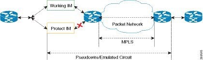
The Card Protection feature is required to protect traffic flow either when an interface module is out of service, when the
software fails or a hardware component has issues. Because card protection is supported only on redundant interface modules,
traffic is switched to the protect interface module when the active interface module does not respond, and vice-versa.
Note
This feature does not require any change in the patch panel of the interface modules.
In card protection, a Y Cable is used to multiplex the signal from the patch panel to both the ports of active and protect
interface modules. Both ports receive the signal, but only the active interface module transmits the signal from its port.
Figure 1. Y Cable
To support the Card Protection feature, the configuration on the active and protect interface module must be same. To achieve
this, a virtual interface module is created with the same interface module type as the active interface module. A virtual
controller is also created, which broadcasts the configuration to both the interface modules. The configuration on the physical
controllers is then blocked and you can make configuration changes only on the virtual controller. The user configuration
can only be performed on the virtual controller.
The virtual controller supports CEM level configuration and all other configurations. These configurations are blocked on
physical controllers.
In card protection, a Y cable is used to multiplex the signal from the patch panel to both the ports of active and standby
interface modules. Both the active and protect ports receive the signal, but only the active port transmits the signal from
its port. Protect port transmitter is disabled.
Card Protection Switchover
The following table shows the card protection switchover trigger and time to complete the switchover between the working and
protect interface module.
Trigger
Time
Interface Module Reload with CLI OIR
Less than 50 millisecond
Non-responsive Interface Module Process (interface module reloads on its own, the reload is initiated due to software error)
100 millisecond to 200 millisecond
Interface Module shuts down due to high temperature
Less than 50 millisecond
Interface Module shuts down using CLI
Less than 50 millisecond
Interface Module stops using CLI
Less than 50 millisecond
Card Physical Jackout
100 millisecond to 200 millisecond
Serializer/Deserializer (SerDes) Failures
250 millisecond to 1 second
Alarm Based Switchover
Based on Hold Over Time or Soak Time
Card Protection Commands
20 millisecond to 30 millisecond
Non-responsive Interface Module Process (interface module reloads on its own, the reload is initiated due to software error)
200 millisecond to 1 second
Card Physical Jackout
200 millisecond to 1 second
Alarm Based Switchover
Alarm based switchover is only applicable for Loss Of Signal (LOS) alarm. Switchover happens only when the number of ports
with LOS alarm in working interface module is greater than that on the protect interface module.
Each card protection group maintains a weight for each working and protect interface module. This weight is updated when the
LOS alarms are asserted or cleared. The switchover happens only if the weight of working interface module and protect interface
module stays same for a certain amount of time called soak time.
When there is any issue with the Patch Panel, both working interface module and protect interface module have the same number
of LOS alarms (weights are same). Hence, switchover does not happen.
Restrictions
Card physical jack out convergence time for card protection switchover is more than 50 milliseconds.
The time taken to restart the interface module due to any software error is more than 50 milliseconds.
Alarm toggle on active or backup card causes at least one card protection switch.
When BERT is started from the virtual controllers, the syslog displays the physical controllers instead of the virtual controller
port.
Supported Features on Interface Module
The supported features are:
Switching Mode
Non-revertive mode
Revertive mode
Alarm Based Switchover
SerDes Based Switchover
Adaptive Clock Recovery (ACR) on virtual CEM
Differential Clock Recovery (DCR) on virtual CEM
Maintenance Commands
Lockout
Force
Manual
Note
All controller configurations are performed on the virtual controller.
You can create card protection with one slot (either primary or backup) and the remaining slots can be added later.
Configuring Maintenance Commands
To configure maintenance commands:
enableconfigure terminalcard-protection4primary slot0bay0backup slot0bay5endcard-protection4card-protection [manual {backup|primary} | force {backup|primary} | lockout]
end
Note
Maintenance commands are not synced in the standby environment. After Redundancy Force Switchover (SSO), maintenance commands
must be executed again on the new active environment.
Priority Table
The following table shows the priority of the actions:
Priority
Configurations
1
Lockout
2
Force
3
Alarm or Card Failure
4
Manual Switch
5
Revert
Configuring T3/E3 Card Protection
Pre-requisites
The interface module should be free from any configuration.
The card protection number 1 to 16 refers to the Card Protection Group Number (CPGN).
Note
This is a non-revertive mode.
Configuring Virtual Card and Virtual Controller:
When card protection group is configured, it creates virtual card for card protection object, denoted by 8/x/port. Slot 8
is a fixed slot number for all card protection-created virtual card. Bay number ‘x’ is derived from the CPGN, where x=CPGN-1.
Since card protection group number ranges from 1 to16, bay number ranges from 0 to 15. Virtual controllers can be configured
from 8/x/0 to 8/x/47.
Physical Card Configuration:
Configures mode T3/E3 on physical controllers of both primary (0/0) and backup (0/5) card.
To un-configure a CEM group under a virtual controller, first perform shutdown of the virtual controller and then un-configure
the CEM group.
Configuring Revertive Mode
To configure revertive mode:
enableconfigure terminalcard-protection4primary slot0bay0backup slot0bay5endcard-protection4revertive time [30-720]
end
Note
The revertive time ranges from 30 to 720 seconds.
Verifying T3/E3 Card Protection Configuration
Use show card-protection detail command to verify card protection group configuration.
#show card-protection 2 detail
Working(0/1:A900-IMA48T-CNCS4200-48T3E3-CE):
Number of LOS Alarms:7
ok,Active
1:1, Revertive
Protect(0/2:A900-IMA48T-CNCS4200-48T3E3-CE):
Number of LOS Alarms:7
ok,Inactive
1:1, Revertive
Revert Timer : (Not Started)
Last switchover reason :None
Use show xconnect all command to verify xconnect configuration.
#show xconnect all
XC ST=Xconnect    State   S1=Segment1 State     S2=Segment2 State
UP=Up   DN=Down     AD=Admin Down     IA=Inactive
SB=Standby  HS=Hot Standby    RV=Recovering    NH=No Hardware
XC   ST    Segment 1                    S1 Segment 2                      S2
–––––––––––––––––––––––––––––––––––––––––––––––––––––––––––––––––––––––––––––––––––––––––
UP   pri   ac CE8/0/0:0(SATOP T3)        UP mpls 11.1.1.1:112              UP
#
Configuring T1/E1 Card Protection
Configuring Card Protection Group:
enableconfigure terminalcard type t10 2card type t10 1card-protection[1-16]primary slot0bay1backup slot0bay2end
Note
The card protection number 1 to 16 refers to CPGN.
Configuring Virtual Card and Virtual Controller:
When card protection group is configured, it creates virtual card for card protection object, denoted by 8/x/port. Slot 8
is a fixed slot number for all card protection created virtual card. Bay number ‘x’ for virtual card is x =CPGN -1 = 15. Virtual
controllers can be configured from 8/15/0 to 8/15/47.
Physical Card Configuration:
No configuration is required for traffic.
Virtual Card Configuration:
Configures CEM on virtual controller (8/x/port).
Configures xconnect and local connect on CEM interface.
To un-configure a CEM group under a virtual controller, first perform shutdown of the virtual controller and then un-configure
the CEM group.
Configuring Revertive Mode
To configure revertive mode:
enableconfigure terminalcard-protection4primary slot0bay0backup slot0bay5endcard-protection4revertive time [30-720]
end
Note
The revertive time ranges from 30 to 720 seconds.
Verification of T1/E1 Card Protection Configuration
Use show card-protection command to verify card protection group configuration.
#show card-protection 2 detail
Working(0/1:A900-IMA48T-CNCS4200-48T1E1-CE):
Number of LOS Alarms:7
ok,Active
1:1, Revertive
Protect(0/2:A900-IMA48T-CNCS4200-48T1E1-CE):
Number of LOS Alarms:7
ok,Inactive
1:1, Revertive
Revert Timer : (Not Started)
Last switchover reason :None
Use show xconnect all command to verify xconnect configuration.
#show xconnect all | I CE8/15/
UP   pri   ac CE8/15/0:0(SATOP T1)        UP mpls 11.1.1.1:212              UP
#
#show xconnect all | i CE8/15/
72       testLC         CE8/15/11 SAT1 0        CE8/15/12 SAT1 0              UP
#
Associated Commands
The following table shows the commands for the IM configuration:
The Cisco Support website provides extensive online resources, including documentation and tools for troubleshooting and
resolving technical issues with Cisco products and technologies.
To receive security and technical information about your products, you can subscribe to various services, such as the Product
Alert Tool (accessed from Field Notices), the Cisco Technical Services Newsletter, and Really Simple Syndication (RSS) Feeds.
Access to most tools on the Cisco Support website requires a Cisco.com user ID and password.


 Feedback