Cisco Connected Grid WPAN Module for CGR 1000 Series Installation and Cisco Resilient Mesh Configuration Guide (Cisco IOS)
This guide explains how to install the IEEE 802.15.4e/g Cisco Connected Grid Wireless Personal Area Network (WPAN) module and how to configure the Cisco Resilient Mesh (formerly known as CG-Mesh). This guide addresses configuration for a Cisco 1000 Series Connected Grid Router (CGR 1000) installed with Cisco IOS software.
 Note |
The documentation set for this product strives to use bias-free language. For purposes of this documentation set, bias-free is defined as language that does not imply discrimination based on age, disability, gender, racial identity, ethnic identity, sexual orientation, socioeconomic status, and intersectionality. Exceptions may be present in the documentation due to language that is hardcoded in the user interfaces of the product software, language used based on RFP documentation, or language that is used by a referenced third-party product. |
Note |
For detailed information of the WPAN-OFDM module, see Connected Grid Module (CGM) WPAN-OFDM Module - Cisco IOS. |
 Warning |
Only trained and qualified personnel should be allowed to install, replace, or service this equipment. Statement 1030 |
Note |
The Cisco Connected Grid WPAN Module is installed in either of the CGR 1000 series models: Cisco 1120 Connected Grid Router (CGR 1120) or Cisco 1240 Connected Grid Router (CGR 1240). The WPAN module is installed at the factory. Only technicians of Cisco or Cisco partners may install, uninstall, or configure Connected Grid modules. |
For system requirements, important notes, limitations, open and resolved bugs, and last-minute documentation updates, see the Release Notes for CGR 1000 (Cisco IOS) on Cisco.com: http://www.cisco.com/c/en/us/support/routers/1000-series-connected-grid-routers/products-release-notes-list.html.
For translations of the warnings that appear in this document, see the Regulatory Compliance and Safety Information document for your router on Cisco.com:
http://www.cisco.com/en/US/docs/routers/connectedgrid/cgr1000/rcsi/cgr1000.rsci.html
When using the online publications, see the documents that match the Cisco system software version running on the WPAN module.
Hardware Overview
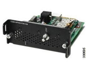
The CGM-WPAN-FSK-NA WPAN module provides IPv6-based, IEEE 802.15.4e/g-compliant, and highly secure wireless connectivity for the CGR to enable Field Area Network (FAN) applications.
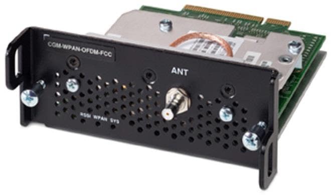
The CGM-WPAN-OFDM-FCC WPAN module is an IEEE 802.15.4g/e/v Radio-Frequency (RF) connection for Cisco 1000 Series Connected Grid Routers (CGR 1000). It delivers 900 MHz RF mesh connectivity to a diverse set of endpoints and support Orthgonal Frequency Division Multiplexing (OFDM).
The WPAN modules allow utilities to converge multiple applications supported by the CGR 1000 across a single RF mesh network. Among these applications are Advanced Metering Infrastructure (AMI), Distribution Automation (DA), Integration of Distributed Energy Resources (DER), and Remote Workforce Automation.
Together, the ruggedized WPAN modules and the CGR 1000 routers provide a versatile platform for diverse Field Area Network (FAN) and Internet-of-Things (IoT) communications deployments aligned with Wi-SUN Alliance objectives for smart utility grids.
The modules are ideal for standards-based IPv6 multihop mesh networks and long-reach solutions. They help enable a high ratio of endpoints to the CGR. The modules provide the following functionality:
-
902-to-928 MHz ISM band frequency hopping technology (configurable frequency range to match your country’s regulations). See Technical Specifications.
-
Dynamic network discovery and self-healing network capabilities that based on IPv6, IEEE 802.15.4 e/g/v, IETF 6LoWPAN, and IETF RPL.
-
Robust security functionality including Advanced Encryption Standard (AES) 128-bit encryption, IEEE 802.1x, and IEEE 802.11i based-mesh security.
-
WPAN module firmware upgrade functionality.
-
WPAN module interface statistics and status.
The WPAN module hardware contains the following:
-
Microcontroller, an RF transceiver operating in the 902-to-928 MHz ISM band.
-
Frequency synthesizer.
-
RF Micro Devices RF6559 front-end module.
Cisco Resilient Mesh has no physical user interfaces such as buttons or display, and therefore all configuration and management occur through Constrained Application Protocol (CoAP) Simple Management Protocol (CSMP) from Cisco IoT Field Network Director (IoT FND). The application module can implement its own user interface and display information obtained using CSMP.
Cisco Resilient Mesh uses the communication module hardware in a way that is compliant with the IEEE 802.15.4e/g MAC/PHY specification. Cisco Resilient Mesh uses the following PHY parameters:
-
Operating Band: 902 to 928 MHz
-
Channel Spacing: 200, 400, 800 kHz
-
Modulation Method: Binary FSK + OFDM
-
CGM-WPAN-FSK-NA—150k baud data rate, 75-bit rate due to FEC
CGM-WPAN-OFDM-FCC—2400 kbps, 1200 kbps, 800 kbps, 400 kbps, 200 kbps, 150 kbps, and 50 kbps data rate
-
Transmit power is automatically configured. See Configuring Transmit Power.
Note |
Only one WPAN module can be installed in any of the slots of the CGR 1120 and CGR 1240. |
This section covers the following topics:
WPAN Models
The following table lists the WPAN module models.
|
Model |
Description |
|---|---|
|
CGM-WPAN-FSK-NA |
Connected Grid Module—IEEE 802.15.4e/g WPAN 900 MHz. |
|
CGM-WPAN-OFDM-FCC |
Connected Grid Module—IEEE 802.15.4e/g/v WPAN 900 MHz. |
WPAN Module Assembly
The following figure shows the CGM-WPAN-FSK-NA WPAN module assembly.
The following figure shows the CGM-WPAN-OFDM-FCC WPAN module assembly.
Front Panel
The following figure shows the front panel of the WPAN module and its components:
|
1 |
Captive screws |
3 |
Antenna connector |
|
2 |
Status LED |
Status LED
The Status LED provides a visual indicator of the available services. The following tables list the status LED colors and their meanings.
|
Color |
Description |
|---|---|
|
Green |
Indicates the RF status:
|
|
LED Name |
Definition |
State |
|---|---|---|
|
RSSI |
Measure of power present in the received radio signal. |
Yellow (Off) / Green (Off): RSSI less than -105 dBm |
|
Yellow (On) / Green (Off): RSSI is -105 to -95 dBm |
||
|
Yellow (Off) / Green (Slow Blink): RSSI is -95 to -75 dBm |
||
|
Yellow (Off) / Green (Fast Blink): RSSI is -75 to -60 dBm |
||
|
Yellow (Off) / Green (Solid On): RSSI greater than -60 dBm |
||
|
WPAN |
WPAN traffic activity detect. |
Yellow (Off) / Green (Off): WPAN port is disabled. |
|
Yellow (On) / Green (Off): Searching for network. |
||
|
Yellow (Off) / Green (Slow Blink): WPAN port is up. |
||
|
Yellow (Off) / Green (Fast Blink): Route is available and DHCPv6 configuration is starting. |
||
|
Yellow (Off) / Green (On): Global IPv6 address is available. |
||
|
SYS |
Indicates module status. |
Green (Blinking): Broadcast slot time complete |
|
Yellow (Blinking): Bootload in process |
||
|
Yellow (Solid): Software update mode in process |
Antenna Connector
The antenna connector is a QMA, panel-mounted, 50-ohm connector for connecting the antenna to the WPAN module.
WPAN Antennas, Connectors, and Cables
The antenna is connected to the QMA, panel-mount, 50-ohm connector located on the faceplate of the WPAN module. Depending on whether the WPAN module is used in the CGR 1240 or CGR 1120, there is a combination of indoor and outdoor cables to connect from the antenna to the QMA connector on the module.
The CGM-WPAN-OFDM module supports the outdoor 5dBi Omni Antenna. This antenna (Cisco Part Number: ANT-LPWA-DB-O-N-5) can be utilized for WPAN, LoRaWAN and ISM technologies.
For more information about antennas, including installation steps, see the Cisco Connected Grid Antennas Installation Guide.
Table 1 lists the Cisco antennas supported by the WPAN module in a CGR 1240. Table 2 lists the Cisco antennas supported by the WPAN module in a CGR 1120.
|
Case Description |
Indoor Cable |
Adapter or Lightning Arrestor |
Outdoor Cable |
Antenna |
|---|---|---|---|---|
|
Case 1: RF900 Integrated Antenna, QMA connector (f), quantity=1 |
RA-QMA(m) to RA-MCX(m), LMR-100, 10.5”, quantity=1, model no. CAB-L100-10-Q-M, Cisco part no. 37-1391-01 |
None |
None |
900 MHz, 3G, 806-960 MHz, 1710-2700 MHz, monopole antenna, chassis mounted, omnidirectional, quantity=1, model no. ANT-MP-INT-OUT-M, Cisco part no. 07-1140-02 |
|
RA-QMA(m) to RA-MCX(m), LMR-100, 17.5”, quantity=1, model no. CAB-L100-17-Q-M, Cisco part no. 37-1380-01 |
||||
|
Case 2: RF900 External Antenna, QMA connector (f), quantity=1 |
RA-QMA(m) to RA-MCX(m), LMR-100, 10.5”, quantity=1, model no. CAB-L100-10-Q-M, Cisco part no. 37-1391-01 |
Bulkhead adapter, MCX(f) receptacle – N(f), quantity=1, Cisco part no.29-5950-01 and Lightning arrestor, DC pass, N(m)-N(f), quantity=1, model no.CGR-LA-NM-NF, Cisco part no. 07-1091-01 |
RA-N(m)-N(m), LMR-400-DB, 20’, quantity=1, model no. CAB-L400-20-N-N, Cisco part no.37-1392-01 |
900 MHz ISM band, omnistick, N(f), quantity=1, model no. ANT-WPAN-OM-OUT-N, Cisco part no.07-1163-02 Outdoor omni-directional, 863-928 MHz, dipole, N-female,5dBi, model no. ANT-LPWA-DB-O-N-5 |
|
RA-N(m)-N(m), LMR-600-DB, 30’, quantity=1, model no.CAB-L600-30-N-N, Cisco part no.37-1396-01 |
|
Case Description |
Indoor Cable |
Adapter or Lightning Arrestor |
Outdoor Cable |
Antenna |
|---|---|---|---|---|
|
Case 1: RF900 Omnistick Antenna, QMA connector (f), quantity=1 |
RA-QMA(m) to N(m), LMR-240-FR, 10’, quantity=1, model no. CAB-L240-10-Q-N, Cisco part no. 37-1351-02 |
Lightning arrestor, N(f)-N(f), quantity=1, model no. CGR-LA-NF-NF, Cisco part no. 07-1158-01 |
RA-N(m) to N(m), LMR-400-DB, 20’, quantity=1, model no. CAB-L400-20-N-N, Cisco part no. 37-1392-01 |
900 MHz ISM band, omnistick, 5 dBi gain, N(f), quantity=1, model no. ANT-WPAN-OM-OUT-N, Cisco part no. 07-1163-01 |
|
RA-QMA(m) to N(m), LMR-240-FR, 15’, quantity=1, model no. CAB-L240-15-Q-N, Cisco part no. 37-1352-02 |
RA-N(m)-N(m), LMR-600-DB, 30’, quantity=1, model no. CAB-L600-30-N-N, Cisco part no. 37-1396-01 |
|||
|
RA-QMA(m) to N(m), LMR-240-FR, 20’, quantity=1, model no. CAB-L240-20-Q-N, Cisco part no. 37-1353-02 |
Installing and Removing the Module
Installation Guidelines
Note |
The WPAN module can be installed in any slot of the CGR 1120 and CGR 1240. |
Before installing the WPAN module, verify that the following guidelines have been met:
-
Clearance to the I/O side view is such that the LED can be read.
-
Airflow around the WPAN module and through the vents is unrestricted.
-
Temperature around the unit does not exceed 140 degrees F (60 degrees C). If the WPAN module is installed in a closed or multi-rack assembly, the temperature around it might be higher than normal room temperature.
-
Relative humidity around the WPAN module does not exceed 95% (non-condensing).
-
Altitude at the installation site is not higher than 10,000 feet.
-
After replacing or installing a module in the router, you must update the label (on the router exterior) that lists the module types contained in the router. The label must list the FCC ID number and the IC Certification number for each module installed in the router.
Before installing the OFDM module, verify that the following guidelines have been met:
-
The module can be located in the same host as - and co-transmit with a cellular radio and a WiFi radio but not with any other radios.
-
This device complies with part 15 of the FCC Rules. Operation is subject to the following two conditions: (1) This device may not cause harmful interference, and (2) this device must accept any interference received, including interference that may cause undesired operation.
-
Installations of this product are limited to the CGR1000 router product series.
-
Usage of antenna and antenna cabling options other than those listed in Table 4 and Table 5 will void the users authority to operate the equipment.
-
Changes or modifications not expressly approved CISCO will void the user's authority to operate the equipment.
-
Installations of this device must ensure a distance of at least 20 cm from persons of the general public to comply with RF-exposure requirements.
Installation Warning Statements
This section includes the basic installation warning statements. Translations of these warning statements appear in the Regulatory Compliance and Safety Information for Cisco Connected Grid Router 1000 Series Routers.
DANGER |
Only trained and qualified personnel should be allowed to install, replace, or service this equipment. Statement 1030 |
DANGER |
To prevent the system from overheating, do not operate it in an area that exceeds the maximum recommended ambient temperature of: 140°F (60°C) Statement 1047 |
DANGER |
To prevent airflow restriction, allow clearance around the ventilation openings to be at least: 1.75 in. (4.4 cm) Statement 1076 |
Installing the Module
Follow these steps to install the module in an available slot in the CGR 1120 or CGR 1240:
 Caution |
Do not hot swap the WPAN module. Power down the module first by using the hw poweroff <slot> command. |
SUMMARY STEPS
- Before you install the WPAN module within the host router (or remove the module), you must power down the router as described in the Cisco 1120 Connected Grid Router Hardware Installation Guide or the Cisco 1240 Connected Grid Router Hardware Installation Guide.
- Insert the WPAN module into the slot as shown in Inserted WPAN Module.
- Using a screwdriver, screw both captive screws into place.
DETAILED STEPS
| Step 1 |
Before you install the WPAN module within the host router (or remove the module), you must power down the router as described in the Cisco 1120 Connected Grid Router Hardware Installation Guide or the Cisco 1240 Connected Grid Router Hardware Installation Guide. |
| Step 2 |
Insert the WPAN module into the slot as shown in Inserted WPAN Module. 
|
| Step 3 |
Using a screwdriver, screw both captive screws into place. |
Removing the Module
Follow these steps to remove the WPAN module from a slot in the CGR 1120 or the CGR 1240:
Caution |
Do not hot swap the WPAN module. Power down the module first by using the hw poweroff <slot> command. |
SUMMARY STEPS
- Using a screwdriver, loosen the two captive screws on the WPAN module.
- Gently pull the WPAN module out of the slot.
DETAILED STEPS
| Step 1 |
Using a screwdriver, loosen the two captive screws on the WPAN module. |
||
| Step 2 |
Gently pull the WPAN module out of the slot.
|
Technical Specifications
Environmental Specifications
Following are the operating temperature ranges for the CGR:
-
CGR 1120: -40 to 140 degrees F (-40 to 60 degrees C)
-
CGR 1240: -40 to 158 degrees F (-40 to 70 degrees C)
The following table lists the environmental specifications for the WPAN module.
|
Environmental—Operational |
Specifications |
|---|---|
|
Temperature—operational |
-40 to 158°F (-40 to 70°C) |
|
Altitude |
Up to 1500 meters |
|
Humidity |
RH95% non-condensing |
|
Vibration |
1.0 g from 1.0 to 150 Hz |
|
Shock |
30 G half sine 6 ms and 11 ms |
Physical-Layer Specifications
The following table lists the interface default values.
|
Parameters |
Default Value |
|---|---|
|
Administrative state |
Enabled |
|
802.15.4 raw data rates |
150 kbaud data rate, 75 bit rate due to FEC |
|
Maximum RF transmit power |
WPAN-FSK: 28 dBm WPAN-OFDM: 30 dBm |
|
Channels |
64 when using 400 kHz frequency hopping |
|
Link retransmission retries |
8 |
The following table lists the default frequencies for each channel. The channel spacing is 400kHz.
|
Channel Number |
Channel Frequency (MHz) |
Channel Number |
Channel Frequency (MHz) |
Channel Number |
Channel Frequency (MHz) |
Channel Number |
Channel Frequency (MHz) |
|---|---|---|---|---|---|---|---|
|
0 |
902.400 |
16 |
908.800 |
32 |
915.200 |
48 |
921.600 |
|
1 |
902.800 |
17 |
909.200 |
33 |
915.600 |
49 |
922.000 |
|
2 |
903.200 |
18 |
909.600 |
34 |
916.000 |
50 |
922.400 |
|
3 |
903.600 |
19 |
910.000 |
35 |
916.400 |
51 |
922.800 |
|
4 |
904.000 |
20 |
910.400 |
36 |
916.800 |
52 |
923.200 |
|
5 |
904.400 |
21 |
910.800 |
37 |
917.200 |
53 |
923.600 |
|
6 |
904.800 |
22 |
911.200 |
38 |
917.600 |
54 |
924.000 |
|
7 |
905.200 |
23 |
911.600 |
39 |
918.000 |
55 |
924.400 |
|
8 |
905.600 |
24 |
912.000 |
40 |
918.400 |
56 |
924.800 |
|
9 |
906.000 |
25 |
912.400 |
41 |
918.800 |
57 |
925.200 |
|
10 |
906.400 |
26 |
912.800 |
42 |
919.200 |
58 |
925.600 |
|
11 |
906.800 |
27 |
913.200 |
43 |
919.600 |
59 |
926.000 |
|
12 |
907.200 |
28 |
913.600 |
44 |
920.000 |
60 |
926.400 |
|
13 |
907.600 |
29 |
914.000 |
45 |
920.400 |
61 |
926.800 |
|
14 |
908.000 |
30 |
914.400 |
46 |
920.800 |
62 |
927.200 |
|
15 |
908.400 |
31 |
914.800 |
47 |
921.200 |
63 |
927.600 |
Regulatory and Compliance Information
For regulatory compliance and safety information for the WPAN module, refer to Regulatory Compliance and Safety Information for the Cisco 1000 Series Connected Grid Routers:
http://www.cisco.com/en/US/docs/routers/connectedgrid/cgr1000/rcsi/cgr1000.rsci.html
Information About Cisco Resilient Mesh and WPAN
Cisco Resilient Mesh and WPAN Overview
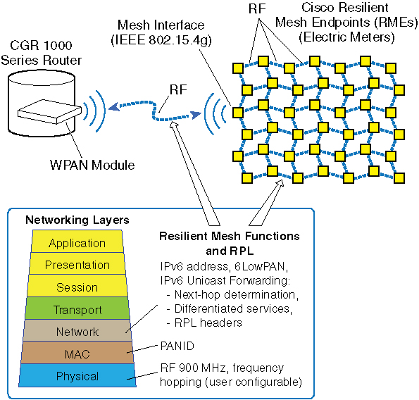
Cisco Resilient Mesh is embedded firmware for Smart Grid assets within a Neighborhood Area Network that supports an end-to-end IPv6 communication network using mesh networking technology. Cisco Resilient Mesh is embedded in Smart Grid endpoints, such as residential electric meters using IP Layer-3 mesh networking technology, that perform end-to-end IPv6 networking functions on the communication module. Resilient Mesh Endpoints (RMEs) support an IEEE 802.15.4e/g interface and standards-based IPv6 communication stack, including security and network management.
Cisco Resilient Mesh supports a frequency-hopping radio link, network discovery, link-layer network access control, network-layer auto configuration, IPv6 routing and forwarding, firmware upgrade, and power outage notification. See Power Outage Notification.
The CGR runs the IPv6 Routing Protocol over Low Power and Lossy Networks, also known as RPL. The IPv6 Layer-3 RPL protocol is used to build the mesh network. It serves as an RPL Directed Acyclic Graph (DAG) root and stores information reported in Destination Advertisement Object (DAO) messages to forward datagrams to individual nodes within the mesh network.
The network provides a communication platform for two-way wireless communication with Smart Grid assets, such as residential electric meters or distribution automation devices, and supports multiple application services simultaneously, such as Advanced Metering Infrastructure (AMI) and Distribution Automation (DA).
For more information on the IEEE 802.15.4 link, see Frequency Hopping.
You can configure a CGR with dual WPANs for either of the following scenarios:
-
Multiple WPANs can operate in the network, each as independent WPAN and independent Cisco Resilient Mesh. In this configuration, each WPAN forms a separate RPL tree and mesh, and each must have a unique IPv6 prefix and Service Set Identifier (SSID).
-
A WPAN can also operate in a master-slave configuration. The master WPAN owns the RPL tree and the mesh, and all IPv6 and 802.1x traffic flows through the master WPAN from the perspective of the CGR and IoT FND. Conceptually, the slave WPAN acts only as a NIC at the MAC and PHY layer. In that sense, the slave WPAN is attached to the master WPAN. For more information, see Dual-PHY WPAN.
Physical Layer
RMEs use the communication module in a manner that is compliant with the IEEE 802.15.4g PHY standard. The following PHY parameters are determined by the capabilities of the hardware:
-
902-to-928 MHz ISM band, with 64 non-overlapping channels, 400 kHz spacing and 150kbps data rate for 2-FSK; CGM-WPAN-OFDM supports 2-FSK with 200 kHz channel spacing and 50kbps data rates with 129 channels.
-
OFDM Option 1, Option 2, Option 3, and Option 4 802.15.4g. Frequency hopping between up to quantity 31 800 kHz channels, PHY data rates of 50 kbps, 200 kbps, 400kpbs,800 kbps and 1200kbps
-
BFSK modulation
-
Forward Error Correction (FEC) with Interleaving
-
150 kbaud data rate, 75 bit rate due to FEC
See Physical-Layer Specifications for interface default values and default frequencies for each channel.
Media Access Control (MAC) Layer
RMEs implement a proprietary Media Access Control (MAC) layer that utilizes the enhanced frame formats specified by IEEE 802.15.4e-2012 and IEEE 802-15.4g-2012.
Network Discovery
Enhanced Beacon (EB) messages allow communication modules to discover PANs that they can join. RMEs also use EB messages that disseminate useful PAN information to devices that are in the process of joining the PAN. Joining nodes are nodes that have not yet been granted access to the PAN. As such, joining nodes cannot communicate IPv6 datagrams with neighboring devices. The EB message is the only message sent in the clear that can provide useful information to joining nodes. CGRs drive the dissemination process for all PAN-wide information.
The following information is sent in the EB frame:
-
SSID, which is used as a filter so new devices can avoid joining foreign networks.
-
GTK info: Include GTK ID and a SHA256 key hash. Mesh nodes use it during the join process to check if it has the GTK or not. This IE is also used when the GTK is renewed by the FAR. Each node can store up to four keys per PAN and keys for up to two different PANs.
-
Network Info.
-
PAN size: number of RPL nodes. Value only updated by the FAR/RPL root.
-
Path cost to the root: RPL Rank.
-
Unicast/listening Schedule: Used to implement the channel-hopping algorithm.
Joining devices also use the RSSI value of the received EB message to determine if a neighbor is likely to provide a good link. The transceiver hardware provides the RSSI value. Neighbors that have an RSSI value below the minimum threshold during the course of receiving EB messages, are not considered for PAN access requests.
Frame Formats
RMEs support the enhanced frame formats, specified by IEEE 802.15.4e-2012 and IEEE 802-15.4g-2012, that allow link frames to carry the following information:
-
Frequency hopping synchronization
-
Security capabilities in EB frames
-
Received Signal Strength Indication (RSSI) information in acknowledgments for bi-directional link quality estimation
In addition, RMEs use secure, enhanced acknowledgment frames which are the same security mechanisms used to secure data frames.
In CR-Mesh Release 6.4, the frame beacon is updated for Wi-SUN 1.x:
-
Header-IE, IEs:
Wi-SUN FAN defines its own Information Elements (IEs) to support certain operations. Depending on where the MAC management information is encapsulated, IEs defined in Wi-SUN can be divided into two categories: Wi-SUN header IEs, and Wi-SUN payload IEs. A payload IE can be longer than a header IE, and can be encrypted as a part of the payload.
-
Flow Control: unicast Extended Directed Frame Exchange (EDFE)
Link-layer Access Control
RMEs implement link-layer access control mechanisms that follow the functionality defined by the IEEE 802.1X standard for node authentication.
-
Admitting nodes —The access control mechanism follows the concepts established by 802.1X for mutual authentication and 802.11i for group key management. RMEs use certificate-based EAP-TLS to perform mutual authentication with an AAA server. RMEs implement the supplicant, and the CGR implements the authenticator. RMEs use a stateless EAP proxy that forwards EAP messages between the CGR and a joining interface because the joining interface might be multiple mesh hops away from the CGR. CGRs communicate with a standard AAA server using the RADIUS protocol.
-
Evicting nodes —To evict nodes from a network, the CGR must communicate a new Group Temporal Key (GTK) to all nodes in the PAN except those being evicted. The new GTK has a valid lifetime that begins immediately. After the new GTK is distributed to all allowed nodes, the CGR invalidates the old GTK. After the old GTK is invalidated, those nodes that did not receive the new GTK can no longer participate in the network and are considered evicted.
-
Security mode —All data-and-acknowledgment traffic are protected using the IEEE 802.15.4 Counter with CBC-MAC (CCM) security mode.
-
AES-128 keys —All nodes in a PAN share the same AES-128 keys for use with CCM.
-
Device authentication —EAP-TLS, where the CGR serves as the authenticator and communicates with a standard AAA server using RADIUS.
-
Handshake protocol —A handshake protocol similar to 802.11i is used to establish a Pairwise Temporal Key (PTK) between a device and a CGR. The PTK is used to securely distribute the GTK. The same handshake messages might be used to refresh the GTK.
Because communication modules might not be within direct communication range of a CGR, RMEs also implement an EAP proxy service so that communication modules can proxy messages between a joining device and the CGR.
6LoWPAN Adaptation
The 6LoWPAN adaptation layer adapts IPv6 to operate efficiently over low-power and lossy links such as defined by IEEE 802.15.4 (low-rate WPAN (LR-WPANs)). The adaptation layer sits between the IPv6 and IEEE 802.15.4 layers and provides IPv6 header compression, IPv6 datagram fragmentation, and optimized IPv6 Neighbor Discovery.
The 6LoWPAN adaptation feature uses packet-header filtering for packet transmission when transporting IPv6 datagrams within IEEE 802.15.4e frames.
RMEs implement the 6LoWPAN header compression format: >RFC 6282 on Compression Format for IPv6 Datagrams over IEEE 802.15.4-Based Networks . For each IPv6 datagram submitted to the mesh interface for transmission, an RME attempts to compress the IPv6 header to the smallest encoding supported by the header compression mechanism.
Note |
Initial 6LoWPAN RFC 4944 also includes an IPv6 header compression scheme that is now deprecated and replaced by RFC 6282 6LoWPAN header compression. The Cisco CGR implementation for 6LoWPAN header compression implements only RFC 6282. |
For more information on RFC 6282, see http://datatracker.ietf.org/doc/rfc6282/ .
The Cisco 6LoWPAN implementation supports a 1576-byte MTU for Wi-SUN implementation in Cisco Resilient Mesh Release 6.3.
Frequency Hopping
RMEs implement frequency hopping between up to quantity 31 800 kHz channels, PHY data rates of 50 kbps, 150 kbps, 200 kbps, 400 kpbs, 800 kbps, 1200 kbps, and 2400 kbps in the 902-to-928 MHz ISM band. The frequency hopping protocol maximizes the use of the available spectrum by allowing multiple sender-receiver pairs to communicate simultaneously on different channels. The frequency hopping protocol also mitigates the negative effects of narrowband interferers.
RMEs allow each communication module to follow its own channel-hopping schedule for unicast communication and synchronize with neighboring nodes to periodically listen to the same channel for broadcast communication. This enables all nodes within a RME PAN to use different parts of the spectrum simultaneously for unicast communication when nodes are not listening for a broadcast message. Using this model, broadcast transmissions can experience higher latency than with unicast transmissions.
When a communication module has a message destined for multiple receivers, it waits until its neighbors are listening on the same channel for a transmission. The size of a broadcast listening window and the period of such listening windows determine how often nodes listen for broadcast messages together rather than listening on their own channels for unicast messages.
Note |
RMEs implement a leading-edge frequency hopping scheme developed by Cisco. Currently, neither IEEE 802.15.4 nor any other industry standard defines a frequency hopping protocol. |
Unicast Listening Schedule
The unicast schedule supports unicast communication used for communicating MAC commands and IPv6 unicast datagrams.
Each node maintains its own channel-hopping schedule for receiving unicast messages. A unicast schedule is defined by the following parameters:
-
Channel Sequence —A list of channels indexed by a 16-bit integer that a mesh interface follows when listening for unicast transmissions.
-
Slot Duration —The equal-sized time slots of the unicast schedule. A node listens to a single channel for the entire duration of a slot before switching to the next channel in the unicast schedule for listening.
Broadcast Listening Schedule
The Layer-2 broadcast schedule supports broadcast communication used for communicating Layer-3 IPv6 multicast datagrams. The broadcast schedule is established on a CGR and disseminated to all nodes in the PAN using a Trickle-based dissemination protocol. All nodes in the PAN synchronize to only one broadcast schedule. There is no coordination of broadcast schedules between PANs.
The following parameters define the broadcast schedule:
-
Channel Sequence —Lists channels indexed by a 16-bit integer the mesh interface follows when listening for broadcast transmissions.
-
Slot Duration —Specifies equal-sized time-slots for the broadcast schedule.
-
Broadcast Listen Window —Specifies how long a node listens for broadcast messages within a broadcast slot. Broadcast packets must start their transmission within the Broadcast Listen Window to ensure that all neighboring nodes are listening for the broadcast transmission. The Broadcast Listen Window must specify a time that is no greater than the Slot Duration. At the beginning of each broadcast slot, the node switches to the next channel in the broadcast schedule to listen for broadcast transmissions. At the end of the Broadcast Listen Window, the node returns to listening for unicast transmissions until the start of the next broadcast slot. The unicast schedule is free running and the timing remains unaffected by the broadcast schedule. In other words, the broadcast schedule is overlaid on a node unicast schedule.
IPv6 Network Layer
RMEs implement standard IPv6 services. The IPv6 layer forwards IPv6 datagrams between the mesh and serial interfaces. The IPv6 layer also uses the mesh interface to forward IPv6 datagrams across other communication modules.
-
RMEs support both unicast and multicast forwarding. Layer-3 multicast is mapped to Layer-2 broadcast.
-
RFC 768 User Datagram Protocol (UDP) is the recommended transport layer protocol over 6LoWPAN.
-
TCP is not the preferred transport layer over 6LoWPAN and is generally not used by RMEs.
-
The default IPv6 MTU is 1280 bytes. Higher layers might limit the size of link frames to a smaller value. As described in 6LoWPAN Adaptation, the Cisco 6LoWPAN implementation supports a 1576-byte MTU for Wi-SUN implementation in Cisco Resilient Mesh Release 6.3.
IPv6 Protocols
Cisco Resilient Mesh implements the following protocols to support IPv6:
-
RFC 2460: Internet Protocol version 6
-
RFC 4291: IP Version 6 Addressing Architecture
-
RFC 6724: Default Address Selection for Internet Protocol Version 6 (IPv6)
-
RFC 4861: Neighbor Discovery for IPv6
-
RFC 4443: ICMP for the Internet Protocol Version 6 (IPv6)
-
RFC 3315: Dynamic Host Configuration Protocol for IPv6
Autoconfiguration
RMEs implement a DHCPv6 client for IPv6 address autoconfiguration. RMEs also support arbitrary DHCPv6 options (that is, vendor option 17) to allow additional stateless configuration information to be included in DHCPv6 replies from the server. Cisco Resilient Mesh uses the DHCPv6 Rapid Commit option to reduce the traffic to only Solicit and Reply messages, so the DHCPv6 server must support this option.
RMEs implement a DHCPv6 client, while the CGR implements a DHCPv6 Relay Agent. A joining node might not be within range of a CGR and must use a neighboring communication module to make DHCPv6 requests.
On a RME, no DHCPv6 server address needs to be configured. The DHCPv6 client requests are sent to the DHCPv6 Relay Agent on the CGR. The DHCPv6 Relay Agent forwards the DHCPv6 client messages to the DHCPv6 server.
RPL
RMEs perform routing at the network layer using the Routing Protocol for Low-Power and Lossy Networks (RPL):
-
RFC 6550 RPL: IPv6 Routing Protocol for Low-Power and Lossy Networks (RPL) (to establish routes for delivering unicast IPv6 datagrams to their destinations).
-
RFC 6551: Routing Metrics Used for Path Calculation in Low-Power and Lossy Networks
-
RFC 6553: The Routing Protocol for Low-Power and Lossy Networks (RPL) Option for Carrying RPL Information in Data-Plane Datagrams
-
RFC 6554: An IPv6 Routing Header for Source Routes with the Routing Protocol for Low-Power and Lossy Networks (RPL)
-
RFC 6206: The Trickle Algorithm
-
RFC 6719: The Minimum Rank with Hysteresis Objective Function
RPL does the following:
-
Offers a number of advanced features, such as trickle timers limiting the chattiness of the control plane, dynamic link (hop count, throughput, latency, link/path reliability (ETX), link colors), and node routing metrics (node state/attribute, node power levels) for constraint-based routing useful for combined AMI (Advanced Metering Infrastructure) and DA (Distributed Automation) deployments.
-
Supports multi-topology routing with the support of multiple Directed Acyclic Graphs (DAGs) where each DAG is optimized against different constraints and metrics dictated by the objective function.
-
Reduces the probability of loops occurring as well as detects these loops by employing data path validation, and then breaking the loops using local poisoning.
-
CGR and RME implementations support a non-storing mode for RPL.
-
Supports both local repair (faster and sub-optimal) and global re-optimization.
-
RPL constructs the routing tree of the meters.
Each node builds and maintains up to three Destination-Oriented Directed Acyclic Graphs (DODAG) parents that provide a path to the Root CGR.
RMEs implement a non-storing mode because the expected traffic flow for AMI applications primarily flows through the CGR. Implementing non-storing mode helps save memory on RMEs by only storing the DODAG parents and the neighbors on the sub-DAG. In non-storing mode, each node maintains their DODAG parents and uses them as default routes. The routing graph, created by the set of DODAG parents across all nodes, defines the set of upward routes—each node reports their DODAG parents to the CGR so that the router can generate source routes when delivering datagrams across the PAN. Likewise, nodes establish downward routes by advertising their parent set towards the DODAG Root. Because RMEs implement the non-storing mode of RPL, nodes report their parent sets directly to the Root; and, the Root must store the information. The Root uses this information when determining source routes needed for delivering datagrams to individual nodes within the mesh.
RMEs configure the RPL protocol to ensure routes are loop-free by disallowing nodes from selecting DODAG parents that are positioned further away from the CGR.
Route Redistribution of External RPL Routes
CG WPAN module for Cisco Resilient Mesh supports route redistribution of external RPL routes in Cisco Resilient Mesh networks for application modules and MAP-T addresses in DA networks. (See Configuring Redistribution of RPL in Other Routing Protocols).
IPv6 Unicast Forwarding
RMEs implement a route-over architecture where forwarding occurs at the network layer. RMEs examine every IPv6 datagram that they receive and determine the next-hop destination based on information contained in the IPv6 header. RMEs do not use any information from the link-layer header to perform next-hop determination.
RMEs implement the options for carrying RPL information in Data-Plane datagrams ( RFC 6553 ) and Type 4 routing header as specified for RPL in RFC 6554 . The routing header allows a node to specify each hop that a datagram must follow to reach its destination.
The RME communication stack offers four priority queues for QoS and supports differentiated classes of service when forwarding IPv6 datagrams to manage interactions between different application traffic flows as well as control-plane traffic. RMEs implement a strict-priority queuing policy, where higher-priority traffic always takes priority over lower-priority traffic.
The traffic on RMEs is marked by the vendor implementation (configuration functionality is not available). If required, traffic can be remarked on the CGR.
IPv6 Multicast Forwarding
RMEs deliver IPv6 multicast messages that have an IPv6 destination address scope larger than link-local when using a Layer-2 broadcast. When RMEs receive a global-scope IPv6 multicast message, the node delivers the message to higher layers if the node is subscribed to the multicast address. RMEs then forward the message to other nodes by transmitting the same IPv6 multicast message over the mesh interface. RMEs use an IPv6 Hop-by-Hop option containing a sequence number to ensure that a message is not received and forwarded more than once.
Group Multicast
Group multicast can be used to control a specific group of devices by multicast. The devices in one group can cross multiple PANs. This feature is supported on CGEREF2/CGEREF2PLUS/CGEREF3 from Cisco Resilient Mesh Release 6.2.
Note |
This feature only works when MPL is enabled. |
In the following figure, headend services are composed of the third-party application server and FND. Headend router are used for managing and communicating with all nodes in multiple PANs. In an application data collection system, there are multiple groups crossing multiple CGRs to collect different data in the field. The nodes in a group intersperse in multiple PANs.
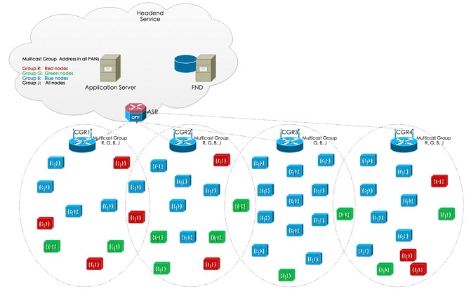
The group multicast configuration is supported on FND or application server. FND manages the group multicast addresses table based on customer’s configuration, while the application server managers the group multicast addresses.
Note |
In Release 6.2, FND doesn't support the group configuration. You need to invoke API to config the group. |
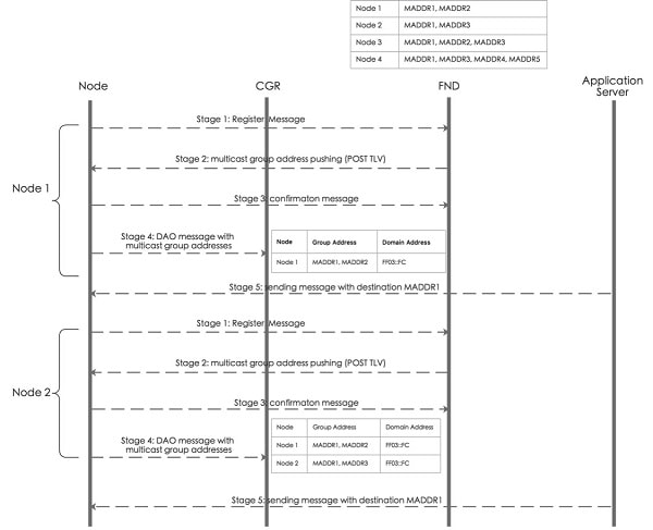
The overall process of FND management can be divided into the following stages:
-
Stage 1: Subscribing IPv6 multicast group address from FND.
After a node joins in the network, it will send the register message to FND shown in above picture. If FND has the preconfigured multicast group table, it will push the multicast group addresses to the node.
-
Stage 2: Managing IPv6 multicast group address on node.
FND posts node’s IPv6 multicast group addresses (maximum is 4) with TLV MulticastGroupSettings to the node. FND can add or delete the multicast group addresses by TLV MulticastGroupSettings.
-
Stage 3: Notifying node’s IPv6 multicast group address to FND.
After a node receive the multicast group addresses, it will send the confirmation message to FND. Then the node can register it into FND. At the same time, node will periodically send its group multicast address into FND.
-
Stage 4: Subscribing all IPv6 multicast group addresses in a PAN on CGR.
Nodes send DAO message directly to CGR. The multicast group information with multicast group addresses and MPL domain will be inserted into one DAO option. CGR will add the multicast group entry for WPAN interface, so that CGR can forward multicast data message from application server to nodes.
-
Stage 5: Sending multicast message from application server to nodes.
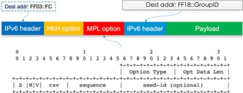
When application server sends a multicast message to nodes, if MPL is enabled on CGR, CGR inserts the MPL domain address (for example, FF03::FC) into original multicast message as shown in the following figure. Then CGR forwards the MPL message to WPAN interface. If node joins in the destination group address, it will receive the message and handle in the upper layer of nodes. If node does not join in the destination group address, it will forward this MPL message because all nodes join in the same MPL domain.
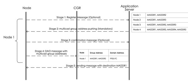
The overall process of application server management can be divided into the following stages:
-
Stage 1: Optionally subscribing IPv6 multicast group address from application server.
After a node joins in the network, the application layer of node can subscribe the multicast group addresses from application server shown in above figure.
-
Stage 2: Managing IPv6 multicast group address on node.
Application server pushes node’s IPv6 multicast group addresses (maximum is 4) to nodes. At the same time, nodes can also call SDK APIs (if_addmaddr, if_delmaddr, if_getmaddrs) to add/delete/get multicast group addresses.
-
Stage 3: Optionally notifying node’s IPv6 multicast group address to application server.
After a node receives the multicast address from application server, it sends the confirmation to the application server.
-
Stage 4: Subscribing all IPv6 multicast group addresses in a PAN on CGR.
Nodes send DAO message directly to CGR. The multicast group information with multicast group addressees and MPL domain will be inserted into one DAO option. CGR will add the multicast group entry for WPAN interface, so that CGR can forward multicast data message from application server to nodes.
-
Stage 5: sending multicast message from application server to nodes.
This stage is the same as the stage 5 of process with FND management.
For more information about configuring group multicast, see .
CoAP Simple Management Protocol (CSMP)
RMEs implement CSMP for remote configuration, monitoring, and event generation over the IPv6 network. CSMP service is exposed over both the mesh and serial interfaces. RMEs use the Cisco IoT FND, which provides the necessary backend network configuration, monitoring, event notification services and network firmware upgrade, as well as power outage and restoration notification and meter registration. IoT FND also retrieves statistics on network traffic from the interface.
IoT FND accesses CSMP over the mesh to manage communication modules. The application module can use the information to perform application-specific functions and support customer-specific diagnostic tools.
RMEs do not support the following:
-
CLI commands—All configuration and management occur only through CSMP
-
No user interface—All configuration and management occur only through CSMP
Note |
In operations, IoT FND is the preferred interface to manage the WPAN module configuration and Cisco Resilient Mesh networks. Only trained and qualified engineers should use the Cisco IOS CLI to configure or monitor a WPAN module. |
Status Information
The following parameters are available from the RMEs through CSMP on IoT FND:
-
Identification
-
UTC time in seconds
-
IEEE 802.15.4 link
-
6LoWPAN link
-
Network interface (for both serial and mesh interface)
-
RPL
-
QoS
-
MAPT
-
Wi-SUN settings
-
Cisco Resilient Mesh firmware
Certificate Management with EST Protocol
The Enrollment over Secure Transport (EST) is a cryptographic protocol that describes a certificate management protocol targeting public key infrastructure (PKI) clients that need to acquire client certificates and associated certificate authority (CA) certificates. EST uses Public-Key Cryptography Standards (PKCS) 10 for certificate requests.
With the EST support enabled, the operational certificates do not need to depend on the manufacturer's PKI. The manufacturer-installed certificate is used only once for initial bootstrapping. After that, all certificates used by the endpoint can be managed using the customer's PKI only. The management of customer-installed certificates does not require manually installing the certificates and keys on the endpoints.
Note |
EST is supported for IR510 WPAN Gateway and IR530 WPAN Range Extender in CR-mesh mode from Cisco Resilient Mesh Release 6.1. EST is supported for IR510 WPAN Gateway, IR530 WPAN Range Extender, and IR529 WPAN Range Extender in Wi-SUN mode from Cisco Resilient Mesh Release 6.3. |
The following certificates are supported:
-
Manufacturer IDevID (birth certificate) − Installed by the manufacturer, using the manufacturer’s PKI, only used for bootstrapping, and immutable.
-
Utility IDevID (passport certificate) − Managed by Utility PKI, enrolled using Manufacturer IDevID, and used only for enrolling the LDevID.
-
LDevID (visa certificate) − Managed by Utility PKI, enrolled using Utility IDevID, and used for 802.1X authentication as operational certificate.
When the endpoint comes with a manufacturer IDevID, after onboarding it acquires a passport and a visa cert from the customer PKI domain. The manufacturer IDevID and passport certificates are used to authenticate and authorize the endpoint when it enrolls for a visa certificate. The visa cert is used to authenticate and authorize the endpoint when it joins the network (802.1x, EAP-TLS).
Cisco Resilient Mesh Release 6.3 supports enrollment and re-enrollment of LDevID cert and FND cert, but not support the refresh of Manufacturer IDevID.
The Cisco Resilient Mesh uses EST over CoAP/DTLS/UDP for certificate enrollment. During the initial bootstrapping process, nodes that have already joined the network (enrolled and authenticated) act as DTLS relays for nodes being bootstrapped.
DTLS relay can be configured by CLI with the following parameters:
-
EST server IP address and port
-
maximum number of sessions
-
maximum session lifetime
For more information on DTLS relay configuration, see Configuring DTLS Relay for EST.
Note |
DTLS relay should only be enabled during the enrollment windows. |
When nodes that are one hop away from the Border Router (BR) are being enrolled, they need to go through the DTLS relay running on the BR. On the BR, layer 1 and layer 2 run on the bridge (running Resilient Mesh) while layer 3 and above run in IOS. The relay operates at layer 3 and layer 4, therefore it is implemented in IOS as well. The relay on the BR will support the same configuration that is supported by the relay running on endpoints. On the BR, the configuration will be done using IOS CLIs.
The relay on the node can be set by TLV170 DtlsRelaySettings. Each node supports at most two relay sessions at the same time. Because each DTLS packet will refresh the relay session, the timeout of each session is 30 seconds.
EST provides an operation for the client to retrieve a bundle of CA certificates from the server, including 802.1x CA and the NMS certificate, as well as the EST-related certificates.
EST supports the enrollment operation of client generating its own private key. With client-side key generation, the client sends a /sen (simpleenroll) request with the CSR. The EST server processes the request and if it is valid, returns the client certificate in a PKCS7 Response. The certificate will include the public key from the CSR.
During bootstrapping this enrollment process is performed twice. First the client authenticates with the Manufacturer IDevID and enrolls the Utility IDevID. After that it authenticates with the Utility IDevID and enrolls the Utility LDevID. The Utility LDevID is then used for the 802.1X authentication.
Certificate re-enrollment can be triggered automatically by an EST client, for example, based on certificate expiry; Or it can be initiated by FND to force re-enroll a particular device or a set of devices.
This certificate auto re-enrollment is controlled by TLV173. A percentage number should be set in TLV173, which means if the certificate's lifetime reaches at the configured percent, node will trigger continuous auto re-enrollment operations until it gets the new certificate.
Power Outage Notification
Cisco Resilient Mesh supports timely and efficient reporting of power outages. In the event of a power outage, Cisco Resilient Mesh enters power outage notification mode and the node stops listening for traffic to conserve energy. Cisco Resilient Mesh triggers functions to conserve energy by notifying the communication module and neighboring nodes of the outage. The outage notification is sent using the same security settings as any other UDP/IPv6 datagram transmission. Communication modules, unaffected by the power outage, gather and forward the information to a CGR.
When power outage happens, if the outage node’s backup power is adequate, its Power Outage Notification (PON) message will be sent as unicast and broadcast once. Any node receiving the PON message will delete this parent based on the hold up time if it exists. Such node is called powered outage node.
The PON message is a CSMP message encapsulated in UDP/IPv6. A specific CSMP URL will be used for PON/PRN. Eui64 address and outage time is contained in PON TLV. Eui64 address, outage and restoration time is contained in power restoration notification (PRN) TLV.
If the outage node’s backup power is limited, its PON message will be sent as broadcast three times. Any node receiving the PON message will delete this parent directly if the route exists and forward it to the outage server. Such node is called normal outage node.
Under outage mode, powered outage node will still send its PON and relay children’s PONs to its parent as unicast. However, normal outage node is in deep sleep mode until the next broadcast transmission. Receiving and unicasting transmission is disabled.
To improve the PON success rate, PON RPL instance is introduced in Wi-SUN mode in the Cisco Resilient Mesh Release 6.2.
-
If node's PON RPL instance is valid and at least one parent is available, parent should be the preferred parent of PON RPL instance.
-
If node's PON RPL instance has no available parent, parent should be the preferred parent from Core RPL instance.
-
If node's PON RPL instance has no available parent, the node must drop the packet from PON RPL instance.
To configure PON RPL, see Configuring PON RPL.
To configure outage server address, see Configuring the Power Outage Server.
Software Upgrade
You can perform firmware upgrades through the CGR CLI (Cisco IOS). WPAN firmware is not upgraded automatically when the CGR is upgraded to a new image integrated with new WPAN firmware.
You can upgrade the WPAN to the firmware version integrated in the CGR image, or you can upgrade to a custom WPAN firmware other than the one integrated in current CGR image. For more information, see Checking and Upgrading the WPAN Firmware Version.
Performance
RMEs support the following performance-enhancing features:
-
Network discovery time —To assist field installations, RMEs support mechanisms that allow a node to determine whether or not it has good connectivity to a valid mesh network. For more information, see Network Discovery.
-
Network formation time —To assist field installations, RMEs use mechanisms that allow up to 5,000 nodes in a single WPAN to go through the complete network-discovery, access-control, network configuration, route formation, and application registration process.
Note
In normal operation, it is recommended that only 2000 nodes in a single PAN are deployed.
-
Network restoration time —The mechanism that aids the rerouting of traffic during a link failure.
-
Power outage notification —For more information, refer to Power Outage Notification.
Cisco Resilient Mesh Security
Cisco Resilient Mesh Network Access Control and Authentication
Network Access Control for CR-Mesh node consists of the following process:
The following figure shows the CR-Mesh authentication overview:
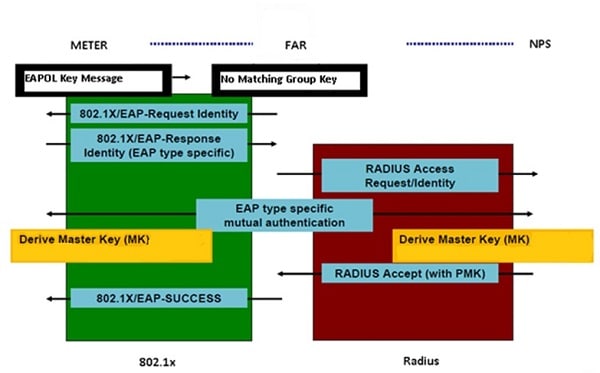
802.1x Authentication Between CR-Mesh Node and AAA Server
When the CR-Mesh node contacts the Border Router (for example, a CGR or an IR8140 router) for the first time, the Border Router redirects the CR-Mesh node for authentication with the AAA server. Only after successful authentication with the AAA server, the CR-Mesh node can participate in the next phase involving key-based authentication between CR-Mesh node and Border Router and hence obtain its GTK from the Border Router.
The type of EAP used in 802.1x is EAP-TLS. The following table shows the EAP-TLS roles and functions.
|
Role in 802.1X Authentication |
Who? |
Function in 802.1X EAP-TLS |
|---|---|---|
|
Supplicant |
Joining CR-Mesh node |
Sends EAP identity and then sends Client Hello, participates in PMK derivation. |
|
Authentication server |
AAA Radius server |
Verifies EAP identity, participates in PMK derivation which is derived from the mutual certificate based authentication that happens as part of the EAP-TLS handshake, and send Authentication ACCEPT or Reject to Authenticator. |
|
Authenticator |
Border Router |
Requests EAP Identity from CR-Mesh node, sends authentication request to AAA Radius server. Relays the EAP after stripping the EAPOL(EAP over LAN (EAPOL) frame and then decides the action to be taken for CR-Mesh node request based on accept or reject it receives from Authentication server. |
|
Split Authenticator |
The first CR-Mesh node that connects the new requesting CR-Mesh node to the PAN |
Acts as the dot1x/EAPOL relay for the new node and relays the EAPOL to the next node in the path all the way to the Border Router. The EAPOL will be encapsulated in UDP by the split authenticator. |
When a CR-Mesh node wants to join the PAN or rejoin the PAN, the following procedure is implemented:
-
Check whether a joining Mesh node has any valid key (PMK, PTK, or GTK). Keys are discussed in detail in 802.11i Key Exchange with the Border Router.
Joining CR-Mesh node initiates the following checks:
-
Joining Mesh node checks if GTK is valid with the neighbor CR-Mesh node that is already authenticated. If GTK is valid, the Border Router immediately joins the PAN and starts communicating. No further action is required.
-
If GTK is not valid, the joining Mesh node checks with the Border Router if the PMK and PTK is valid.
-
If PMK is not valid, the Border Router will initiate full authentication with AAA server and then the 4-way handshake process.
-
If PMK is valid, then the node checks if PTK is valid.
-
If PMK is valid and PTK is valid, the Border Router will communicate GTK to the joining CR Mesh node using PTK.
-
If PMK is valid and PTK is not valid, the Border Router will initiate PTK generation and then communication of GTK to enable the CR-Mesh node to join the PAN.
-
This hierarchical decision process minimizes the security overhead in the normal case, where devices might migrate from network-to-network due to environmental changes or network formation after a power outage. (See Power Outage Notification.)
-
-
If the CR-Mesh node is joining the PAN for the first time, it will not have valid key (PMK, PTK, or GTK). Hence the Border Router asks for EAP identity from the CR-Mesh node and then it sends the Radius Access-Request to the AAA Radius server for the CR-Mesh node.
-
A joining CR-Mesh node or the Supplicant sends EAP identity over EAPOL frames to the Border Router. Supplicant here, refers to the requesting CR-Mesh node that wants to join the PAN. The Border Router will be the authenticator and the AAA Radius server will be the authentication server.
-
The joining node chooses an EAPOL target to send EAPOL frames to. The EAPOL target can be the Authenticator (the Border Router) if the joining node is one hop away from it or it can be another node which has already joined the PAN and acts as the EAPOL Relay. A node acting as EAPOL Relay encapsulates the EAPOL packets into UDP/IPv6 packets and sends them to the Authenticator. If the relay itself is more than one hop away from the Authenticator, other nodes along the path will perform the IPv6 routing necessary for the relay’s IPv6 packet to reach the Authenticator. Similarly, the EAPOL relay receives EAPOL packets encapsulated in UDP/IPv6 packets from the Authenticator and transmits EAPOL frames to the joining node.
-
The Border Router receives and strips the EAPOL, and relays only the EAP frame to the Radius server for authentication.
-
The Radius server verifies the EAP identity information and starts the authentication with the CR-Mesh node, and proceeds to the next step—Key Exchange (see 802.11i Key Exchange with the Border Router).
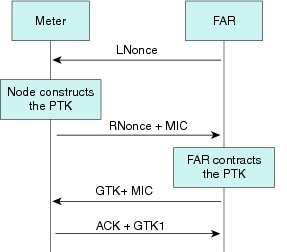
802.11i Key Exchange with the Border Router
The 802.11i Key Management is implemented by using four-way handshake. It is initiated by the Border Router (for example, a CGR or an IR8140 router) and consists of Pairwise Master Key (PMK) confirmation, Pairwise Transient Key (PTK) derivation, and Group Temporal Key (GTK) distribution.
-
If the EAP identity sent by the CR-Mesh node is valid, a PMK is derived from the EAP-TLS handshake where the mutual certificate based authentication happens by the Radius server and the CR-Mesh node respectively. The information used for deriving the PMK is based on the information that is already exchanged between the CR-Mesh node and the Radius server.
-
The Radius server sends a Radius accept message to the Border Router and shares the PMK that has been derived.
-
After the PMK is generated, a PTK is derived by the CR-Mesh node and the Border Router. PTK is derived from MAC address of the CR-Mesh node and the PMK generated in the previous step.
-
Using the PTK derived in the previous step, the Border Router distributes the GTK. The CR-Mesh node needs a valid GTK to join a PAN. The management of GTK is using Field Network Director (FND).
|
Key |
Where it is generated |
|---|---|
|
PMK |
Derived individually on both CR-Mesh node and AAA server |
|
PTK |
Derived individually on both CR-Mesh node and Border Router |
|
GTK |
Border Router derives it but distributes it encrypted in PTK |
Note |
To manage GTKs in a multi-hop mesh network, CR-Mesh introduces novel mechanisms for efficiently checking the consistency of the GTK, PTK, and PMKs. Devices include GTK IDs in IEEE 802.15.4 Enhanced Beacons to quickly verify the freshness of their GTKs. If any device detects an inconsistency in the GTK state, it requests updated GTKs from the Border Router. In addition, devices include a PTK ID (along with the PMK ID) in GTK request messages sent to the Border Router, allowing the Border Router to quickly determine whether to initiate a two-way handshake, four-way handshake, or full EAP-TLS authentication. Including GTK, PTK, and PMK IDs in the key management messages significantly reduces the latency in detecting (and thus distributing) updated GTKs to all devices in the network. |
Note |
Client certification and CA certification size must be less than 1040 Byte; Otherwise the cert is invalid on CR-Mesh device. |
Compromised Node Eviction
A compromised node is one where the device can no longer be trusted by the network and/or operators. Nodes within an IEEE 802.15.4 PAN must possess the currently valid Group Temporal Key (GTK) to send and receive link-layer messages. The GTK is shared among all devices within the PAN and is refreshed periodically or on-demand. By only communicating new GTKs to trusted devices, compromised nodes might be evicted from the network.
Cisco Resilient Mesh Security Warm Boot vs. Cold Boot
Authentication for Cisco Resilient Mesh security behaves differently between a warm-boot versus a cold-boot:
-
A warm boot is when the meter has a working key, in which case authentication has already been established and the meter joins the mesh quickly.
-
A cold boot is when the meter has not yet been authenticated because it is the first time the meter has been authenticated or the meter key has expired.
Dual-PHY WPAN
Note |
CR-Mesh Release 6.4 does not support Dual-PHY WPAN on CGR. |
In a CGR configured with dual-WPAN interfaces, the Dual-PHY WPAN feature enables a WPAN to operate as a slave of a master WPAN. A master WPAN is the same as a regular independent WPAN. Only one slave WPAN can be attached to a master WPAN.
Note |
The Dual-PHY WPAN feature applies to the CGR IOS release only. |
Only the master WPAN has an RPL tree; the slave WPAN has an RPL tree with zero entries. All mesh nodes obtain the IPv6/RPL prefix of the master WPAN. The IPv6/RPL prefix, as well as RPL configurations on the slave WPAN, are ignored. A slave WPAN does not send RPL DODAG Information Object (DIO) messages. Conceptually, the slave WPAN acts only as a NIC at the MAC and PHY layer.
From the point of view of the CGR and IoT FND, all IPv6 and 802.1x/mesh-security traffic flows only through the master WPAN; however, it is correctly routed at the lower layer to the actual master or slave interface. The CGR sees all power outage notification (PON) and power restoration notification (PRN) traffic as flowing only through the master WPAN, even though it may have come from different master or slave interfaces. All traffic statistics are reported under the master WPAN. All non-WPAN commands (ping , traceroute , show interface , etc.) work through the master IPv6 prefix.
The master WPAN shows the link neighbor table for nodes sensed by the master WPAN, and the slave WPAN shows the link neighbor table for nodes sensed by the slave WPAN.
The two WPANs can be mix of RF and PLC. SSIDs do not need to be identical on both WPANs. However, different PANIDs should be configured on each WPAN.
See Configuring the Dual-PHY Master-Slave Relationship for configuration information.
Configuring Cisco Resilient Mesh and the WPAN Module
IoT FND provides the user interface for all Cisco Resilient Mesh configuration and management.
Cisco Resilient Mesh has no CLI and no graphical user interface for configuration or management.
All configuration and management occur only by using IoT FND through the CGR Series WPAN module by using Cisco IOS software commands (Release 15.4(2)CG and greater).
Note |
Your CGR1000 router must be running Cisco IOS Release 15.7(3)M1 (cgr1000-universalk9-bundle.SPA.157-3.M1.bin) or greater to support the CGM WPAN-OFDM Module. |
Note |
Your CGR1000 router must be running Cisco IOS Release 15.8(3)M2 (cgr1000-universalk9-bundle.SPA.158-3.M2.bin) or greater to support the CGM WPAN-OFDM Module in Wi-SUN mode. |
Configuring the WPAN Interface
At the CGR 1000, configure the WPAN Module interface as follows:
cgr1000_wpanmodule# config terminal
cgr1000_wpanmodule(config)# interface wpan  <slot |port >
cgr1000_wpanmodule(config-if)#
Enabling dot1x, mesh-security, and DHCPv6
You must enable the dot1x (802.1X), mesh-security, and DHCPv6 features to configure the WPAN interface.
To enable these features, use the following command:
dot1x system-auth-control
For dot1x, the WPAN interface configuration requires:
dot1x pae authenticator
See Sample Router Configuration.
For configuring mesh security, see Configuring Cisco Resilient Mesh Security.
For DHCPv6, you will also need in your WPAN running configuration:
ipv6 dhcp relay destination <IPv6 address >
See Sample Router Configuration.
In Cisco IOS on the CGR, various WPAN radio related commands are under the ieee154 parameter:
Router(config-if)#ieee154 ?
  beacon-async  IEEE154 async beacon parameters
  channel       Channel (for hw testing use only. 254 is channel hopping)
  dwell         Channel dwell configuration for regional compliance
  notch         Channel notch configuration for regional compliance
  panid         PAN ID
  ssid          SSID
  txpower       Transmission power configuration (hardware dependent)
Naming Your PAN
To configure the name of your IEEE 802.15.4 Personal Area Network Identifier (PAN ID), use the following WPAN command:
Router(config-if)# ieee154 panid ?
  <0-65535>  Enter a value between 0 and 65535
Router (config-if)# ieee154 panid 2121
For sample configuration, see show wpan config.
Naming the SSID
The Service Set Identifier (SSID) identifies the owner of the RME. The SSID is set on a RME in manufacturing, and that same SSID must also be configured on the CGR WPAN interface.
To configure the name of the SSID, use the ssid command ieee154 ssid <ssid_name >, for example:
Router(config)# interface wpan 3/1
Router(config-if)# ieee154 ssid ?
  WORD  ssid string (Max size 32)
Router(config-if)# ieee154 ssid myWPANssid
For sample configuration, see show wpan config.
Configuring Transmit Power
Note |
Transmit power must match the local regulation and be aligned with the Cisco Resilient Mesh value, which can be monitored through IoT FND. |
The actual maximum possible power emitted by the radio antenna is approximately 28 to 30 dbm. However, this is not directly, nor linearly, mapped to the txpower designation in the configuration. The txpower in the configuration specifies the txpower setting in the physical hardware (chip). However, the radio signal out of the hardware chip must travel through the amplifier, front end, antenna, etc., which causes the output power of the chip to be less than the actual electro-magnetic signal that is emitted into the air.
Values range from 2 (high) to the default value of -34 dBm (low) as shown in the following table:
Note |
This table is used for FSK WPAN module. For OFDM WPAN module, the txpower range is different based on different PHY modes. |
|
txpower Value |
Configured Power Value (dBm) |
Actual Power (dBm) |
|---|---|---|
|
High |
2 |
28 (For outdoors; the recommended value) |
|
Low |
-34 |
0 (For indoor lab testing) |
The range provided in txpower configuration is an integer range, which is a superset of all the configurable values available.
Router(config-if)# ieee154 txpower ?
  <-65 - 64>  Enter a value between -65 and 64
*Default value is -34
To configure the transmit power for outdoor usage, specify a higher transmit power, such as:
Router (config-if)# ieee154 txpower 30
For sample configuration, see show wpan config.
Naming the Notch
A notch is a list of disabled channels from the 902-to-928 MHz range. If there is no notch at all, then all channels are enabled. if there is a notch [x, y], then channels between x and y are disabled.
Notch configuration must comply with your regional regulations (for example, a notch configuration is not required for U.S.). Notch configuration must match between the WPAN interface of the CGR and the RME.
For sample configuration, see show wpan config.
Note |
A channel list is a list of enabled channels. |
You can view the notch by using the following command:
Router(config-if)# ieee154 notch ?
  <0-63>  channel id
Router (config-if)# ieee154 notch 10-15, 30-35
Router (config-if)# end
Router# config in-hardware notch
notch: [10, 15]
notch: [30, 35]
Router# show wpan slot/port hardware channel-list
channellist: 0 1 2 3 4 5 6 7 8 9 16 17 18 19 20 21 22 23 24 25 26 27 28 29 36 37 38 39 40
41 42 43 44 45 46 47 48 49 50 51 52 53 54 55 56 57 58 59 60 61 62 63
Configuring the CGM WPAN OFDM Module
The following table shows the CLI interface commands for the CGM WPAN-OFDM Module.
|
Command |
Definition |
||
|---|---|---|---|
|
ieee154 phy-mode <1-255> |
Defines the IEEE154 PHY mode. Supported Phy-Modes: 64:Rate=50 kb/s; Modulation=2FSK; Modulation Index=1.0; FEC=OFF; Channel Spacing=200 kHz 66:Rate=150 kb/s; Modulation=2FSK; Modulation Index=0.5; FEC=OFF; Channel Spacing=400 kHz 134:Rate=2400 kb/s; Modulation=OFDM; Option=1; MCS=6; Channel Spacing=1200 kHz 144:Rate=50 kb/s; Modulation=OFDM; Option=2; MCS=0; Channel Spacing=800 kHz 147:Rate=400 kb/s; Modulation=OFDM; Option=2; MCS=3; Channel Spacing=800 kHz 149:Rate=800 kb/s; Modulation=OFDM; Option=2; MCS=5; Channel Spacing=800 kHz 150:Rate=1200 kb/s; Modulation=OFDM; Option=2; MCS=6; Channel Spacing=800 kHz 161:Rate=50 kb/s; Modulation=OFDM; Option=3; MCS=1; Channel Spacing=400 kHz 163:Rate=200 kb/s; Modulation=OFDM; Option=3; MCS=3; Channel Spacing=400 kHz 165:Rate=400 kb/s; Modulation=OFDM; Option=3; MCS=5; Channel Spacing=400 kHz 166:Rate=600 kb/s; Modulation=OFDM; Option=3; MCS=6; Channel Spacing=400 kHz 182:Rate=300 kb/s; Modulation=OFDM; Option=4; MCS=6; Channel Spacing=200 kHz |
||
|
ieee154 txpower <-65 - 35 > |
Enter a value between -65 and 35, where 25 is the default transmission power value. |
||
|
wisun-mode |
Enable Wi-SUN mode configuration. After the wisun-mode configuration, WPAN should be reload. |
||
|
[no ] rpl dag-lifetime <15 -255> |
Enter a value between 15 and 255 seconds. Default is 120. |
||
|
[no ] rpl storing-mode |
Enter command to enable RPL storing mode on the interface. Enter no rpl storing-mode to disable the command.
|
Note |
Cisco Resilient Mesh Release 6.3 only supports phymode 64, 66, 161, 162, 163, 165, and 166 for OFDM-WPAN. |
Sample Configuration
interface Wpan4/1
no ip address
wisun-mode
ip broadcast-address 0.0.0.0
no ip route-cache
ieee154 beacon-async min-interval 10 max-interval 20 suppression-coefficient 1
ieee154 dwell window 20000 max-dwell 400
ieee154 panid 106
ieee154 phy-mode 66
ieee154 ssid edgecompute-secure
ieee154 txpower 25
rpl dag-lifetime 120
rpl dio-dbl 5
rpl dio-min 16
rpl version-incr-time 120
authentication host-mode multi-auth
authentication port-control auto
ipv6 address 2046:FACE::/64
ipv6 dhcp relay destination 2001:FACE::200
no ipv6 pim
Configuring Adaptive Modulation
Adaptive modulation enhances the backward compatibility with the classic Cisco Resilient Mesh network and improves the transmitting ability in the classic Cisco Resilient Mesh network. Adaptive modulation is supported on both Wi-SUN and Cisco mesh mode.
The following example shows the configuration of adaptive modulation in Wi-SUN mode:
(config)#interface wpan 4/1
(config-if)#ieee154 phy-mode
Supported Phy-Modes:
64:Rate=50 kb/s; Modulation=2FSK; Modulation Index=1.0; FEC=OFF; Channel Spacing=200 kHz
96:Rate=50 kb/s; Modulation=2FSK; Modulation Index=1.0; FEC=ON; Channel Spacing=200 kHz
66:Rate=150 kb/s; Modulation=2FSK; Modulation Index=0.5; FEC=OFF; Channel Spacing=400 kHz
98:Rate=150 kb/s; Modulation=2FSK; Modulation Index=0.5; FEC=ON; Channel Spacing=400 kHz
161:Rate=50 kb/s; Modulation=OFDM; Option=3; MCS=1; Channel Spacing=400 kHz
162:Rate=100 kb/s; Modulation=OFDM; Option=3; MCS=2; Channel Spacing=400 kHz
163:Rate=200 kb/s; Modulation=OFDM; Option=3; MCS=3; Channel Spacing=400 kHz
164:Rate=300 kb/s; Modulation=OFDM; Option=3; MCS=4; Channel Spacing=400 kHz
165:Rate=400 kb/s; Modulation=OFDM; Option=3; MCS=5; Channel Spacing=400 kHz
166:Rate=600 kb/s; Modulation=OFDM; Option=3; MCS=6; Channel Spacing=400 kHz
(config-if)#ieee154 phy-mode 161 163 165 166
The Phy mode change causes the following config changes:
channel to 254; notch to none;
Note |
When configuring multiple PHY modes, the first mode MUST be the base mode. |
Note |
Adaptive modulation only supports to configure the same OFDM option phymode or the same OFDM option plus FSK phymode. |
Use the following command to check PHY mode configuration:
#show wpan 4/1 hardware config
Note |
The adaptive modulation feature in Release 6.4 is incompatible with Release 6.2 and 6.3. But they can still communicate on base PHY mode. |
In Wi-SUN FAN 1.1, for NA/BZ region, the mandatory PHY modes are: 2, 5, 38, 54, 70, 86. The optional PHY modes are: 3, 8, 34, 35, 36, 37, 51, 52, 53, 54, 68, 69, 84, 85.
The following adaptive modulation cases are supported in CR-Mesh Release 6.4:
-
FSK (50kbps) + OFDM_Option3 (200kbps+400kbps+600kbps)
-
FSK (50kbps) + OFDM_Option4 (300kbps)
-
FSK (150kbps) + OFDM_Option1 (2400kbps)
-
FSK (150kbps) + OFDM_Option3 (200kbps+400kbps+600kbps)
Based on sensitivity and SNR threshold, the following cases for adaptive rate are supported in CR-Mesh Release 6.4:
-
Option 2: 4 modes (0x96-1200kbps, 0x95-800k, 0x93-400k, 0x90-50k)
-
Option 3: 4 modes (0xA6-600kbps, 0xA5-400k, 0xA3-200k, 0xA1-50k)
Mapping of PHY Mode ID Between Release 6.4 and Release 6.2/6.3
The following table provides the mapping of FSK Phy Mode ID between Release 6.4 and Release 6.2/6.3:
|
Phy Mode ID without FEC |
Modulation |
PHY Modes Reference |
||
|---|---|---|---|---|
|
Release 6.4 |
Release 6.2/6.3 |
Symbol Rate |
Modulation Index |
|
|
2 (0x02) |
64 (0x40) |
50 |
1.0 |
#1b |
|
5 (0x05) |
66 (0x42) |
150 |
0.5 |
#3 |
The following table provides the mapping of OFDM Phy Mode ID between Release 6.4 and Release 6.2/6.3:
|
Phy Mode ID |
Modulation |
||||
|---|---|---|---|---|---|
|
Release 6.4 |
Release 6.2/6.3 |
Option |
MCS |
Data Rate |
CH Space |
|
38 (0x26) |
134 (0x86) |
1 |
6 |
2400 kbps |
1200 kHz |
|
48 (0x30) |
144 (0x90) |
2 |
0 |
50 kbps |
800 kHz |
|
51 (0x33) |
147 (0x93) |
2 |
3 |
400 kbps |
800 kHz |
|
53 (0x35) |
149 (0x95) |
2 |
5 |
800 kbps |
800 kHz |
|
54 (0x36) |
150 (0x96) |
2 |
6 |
1200 kbps |
800 kHz |
|
65 (0x41) |
161 (0xA1) |
3 |
1 |
50 kbps |
400 kHz |
|
67 (0x43) |
163 (0xA3) |
3 |
3 |
200 kbps |
400 kHz |
|
69 (0x45) |
165 (0xA5) |
3 |
5 |
400 kbps |
400 kHz |
|
70 (0x46) |
166 (0xA6) |
3 |
6 |
600 kbps |
400 kHz |
|
86 (0x56) |
182 (0xB6) |
4 |
6 |
300 kbps |
200 kHz |
Configuring Group Multicast
Note |
This feature is not supported in Cisco Resilient Mesh Release 6.3. |
Use the following commands to configure group multicast:
Enable MPL:
(config)#fan-mpl domain 0Check the mcast address reported by node:
#show wpan 4/1 rpl mcast-info domains#show wpan 4/1 rpl mcast-info groupsAdd multicast agent interface (uplink interface):
(config-if)#mcast-agent interface fx/xAdd multicast agent port:
(config-if)#mcast-agent portAdd multicast agent group:
(config-if)#mcast-agent group-join ?
  X:X:X:X::X multicast group address
Check multicast agent port, interface, and groups:
#show wpan 4/1 mcast-agent ?
 group-join multicast group address
 interface mcast-interface
 ports Mcast optional ports
Configuring RPL
To determine the available RPL functions, query the rpl command:
Router(config-if)# rpl ?
  dag-lifetime       RPL DAG lifetime in minutes
  dio-dbl            RPL DIO dbl value
  dio-min            RPL DIO min value
  route-poisoning    Route poisoning
  version-incr-time  Version increment time in minutes
Note |
For more information about RPL, refer to "RFC 6550: RPL: IPv6 Routing Protocol for Low-Power and Lossy Networks". |
Setting the Minimum Version Increment
To set the minimum time between RPL version increments, use the version-incr-time command:
Router(config-if)# rpl version-incr-time ?
  <10-600>  Enter a value between 10 and 600
Router (config-if)# rpl version-incr-time 15
For sample configuration, see show wpan config.
Setting the DODAG Lifetime Duration
To set the Destination-Oriented Directed Acyclic Graph (DODAG) lifetime duration, use the dag lifetime command. Each node uses the lifetime duration parameter to drive its own operation (such as Destination Advertisement Object (DAO) transmission interval). Also, the CGR uses this lifetime value as the timeout duration for each RPL routing entry.
Router(config-if)# rpl dag-lifetime ?
  <60-255>  Enter a value between 60 and 255
Router(config-if)# rpl dag-lifetime 120
For sample configuration, see show wpan config.
Configuring the DODAG Information Object Parameter
To configure the DODAG Information Object (DIO) parameter per the RPL IETF specification, use the rpl dio-min command.
Caution |
This command must only be used by an expert RPL protocol administrator. |
Router(config-if)# rpl dio-MIN ?
  <14-24>  Enter a value between 14 and 24
Router(config-if)# rpl dio-MIN 21
For a sample configuration, see show wpan config.
To set the DIO double parameter as per the RPL IETF specification, use the dio-dbl command. DIO double is a doubling factor parameter used by the RPL protocol.
Caution |
This command must only be used by an expert RPL protocol administrator. |
Router(config-if)# rpl dio-dbl ?
  <0-10>  Enter a value between 0 and 10
Router(config-if)# rpl dio-dbl 5
For sample configuration, see Sample Router Configuration.
Configuring RPL Metric Container and DODAG Config Option
RPL metric container (dag_size, etx, and hop_count) provides more information of the topology. CR-Mesh 6.4 includes more RPL metrics in the DAO upstream message to help FND showcase more meaningful information and display the data on the google map as well as the device page.
The following commands on CGR configure whether BR’s DIO carries DAG Metric Container option and the private flag of DODAG configuration option.
-
rpl option metric-container—Include metric option in DIO message in Wi-SUN mode core instance. no rpl option metric-container is used to disable this configuration.
-
rpl option dodag-config cisco-flag <0-1>—Set Cisco flag to a value between 0 and 1 in DODAG configuration option in Wi-SUN mode core instance.
Configuring IPv6
To determine the available IPv6 functions, query the ipv6 commands:
Router (config-if)# ipv6 ?
To enable IPv6 on an interface, use:
Router(config-if)# ipv6 enable
Configuring IPv6 DHCP Relay
To configure the IPv6 DHCP relay, use the ipv6 dhcp relay command:
Router (config-if)#ipv6 dhcp relay destination
The IPv6 address of the DHCP server displays as:
!
interface Wpan3/1
 no ip address
 ip broadcast-address 0.0.0.0
 no ip route-cache
 ieee154 beacon-async min-interval 120 max-interval 900 suppression-coefficient 1
 ieee154 panid 7220
 ieee154 ssid myWPANssid
 rpl dio-dbl 5
 rpl dio-min 21
 rpl route-poisoning
 authentication host-mode multi-auth
 authentication port-control auto
 ipv6 address 2091:1:1:1::/64
 ipv6 enable
 ipv6 dhcp relay destination  2010:A0B0:1001:22::2
 dot1x pae authenticator
end
!
Configuring Redistribution of RPL in Other Routing Protocols
CGR allows redistribution of the RPL routes including the WPAN prefix as well as the external RPL routes such as MAP-T addresses assigned to DA gateways or prefixes assigned to Application Modules.
Before redistributing RPL in OSPFv3, you must configure OSPFv3 on the uplink tunnel interface:
Router (config-if)# router ospfv3 process_id
Router (config-if)# ipv6 ospf process_id area area_id
To redistribute RPL in OSPFv3, use the following route-map and router OSPFv3 commands:
<!--snip--!>
!
interface Loopback0
 ip address 20.211.0.11 255.255.255.255
 ipv6 address 2001:420:7BF:7E8::B/128
 ipv6 enable
 ipv6 ospf 1 area 1
!
interface Tunnel0
 description IPsec tunnel to SOL-ASR-7
 ip unnumbered Loopback0
 ip pim sparse-mode
 ipv6 unnumbered Loopback0
 ipv6 enable
 ipv6 mld join-group FF38:40:2006:DEAD:BEEF:CAFE:0:1
 ipv6 ospf 1 area 1
 ipv6 ospf mtu-ignore
 tunnel source Dialer1
 tunnel destination dynamic
 tunnel protection ipsec profile FlexVPN_IPsec_Profile
!
<!--snip--!>
!
router ospfv3 1
 !
 address-family ipv6 unicast
  redistribute connected route-map WPAN
  router-id 2.0.0.7
 exit-address-family
<!--snip--!>
!
!
route-map WPAN permit 10
 match interface Wpan5/1
!
<!--snip--!>
CGR-JAF1626AQED#show ipv6 ospf neighbor
            OSPFv3 Router with ID (2.0.0.7) (Process ID 1)
Neighbor ID     Pri   State           Dead Time   Interface ID    Interface
20.0.0.3          0   FULL/  -        00:00:30    27              Tunnel0
CGR-JAF1626AQED#
Configuring PON RPL
Use the following command to configure PON RPL:
(config-if)#rpl pon ?
  dio-dbl   RPL PON DIO dbl value
  dio-min   RPL PON DIO min value
  instance  Enable RPL PON instance
Configuring the Power Outage Server
You can configure the power outage server with the outage server command. We recommend an IPv6 address or IPv6 resolvable FQDN of a server.
Note |
In most cases, the outage server is your IoT FND server. |
Router(config-if)# outage-server ?
  WORD        IPv6 address resolvable hostname
  X:X:X:X::X  IPv6 address (aaaa:bbbb:cccc:dddd:eeee:ffff:gggg:hhhh, aaaa::bbb)
To configure the power outage server, use one of the following outage server commands:
Router (config-if)# outage server 2001:c1::8a43:e1ff:fec3:2aa
or
Router (config-if)# outage server nms.cisco.com
For sample configuration, see Sample Router Configuration.
Configuring QoS
To specify a QoS service policy, use the qos service-policy command.
See the Quality of Service Solutions Configuration Guide Library, Cisco IOS Release 15M&T for QoS configuration information.
Configuring Cisco Resilient Mesh Security
RMEs use the IEEE 802.1X protocol, known as Extensible Authentication Protocol over LAN (EAPOL), for authentication.
Note |
Cisco Resilient Mesh doesn't support TLS 1.1. If the radius server doesn't support TLS1.2, you need to disable TLS 1.1 on radius server for compatibility. |
Configuring Mesh Key
Router (config-if)# mesh-security ?
  delete  Delete the session(s)
  expire  Force Expire
  set     Set parameters
To set the mesh key, use the mesh-security set mesh-key command in privileged mode:
Router# mesh-security set mesh-key interface wpan <slot>/<port> key ?
  Hex-string  Key - even number (max. 32) of hex digits
Router# mesh-security set mesh-key interface wpan 3/1 key 1234567891234567 < --# Your secret key.
To configure the mesh key lifetime, use the mesh-security mesh-key command in interface configuration mode:
Note |
Only call this command if you are an expert mesh-security administrator. |
Note |
The Mesh-key lifetime value should be less than 120 days (10368000 seconds). |
Router(config-if)# mesh-security ?
  authentication-timeout     Set authentication timeout
  keystore-update-period     Set keystore update period
  max-active-authentication  Set number of parallel authentications
  max-active-key-exchange    Set number of parallel key exchanges
  mesh-key                   Mesh key

Router(config-if)# mesh-security mesh-key lifetime ?
  <60-2592000>  Key lifetime (in seconds)

Router (config-if)# mesh-security mesh-key lifetime 60
Note |
Mesh-Security config and keys do not appear in the CGR configuration as shown by show running-config or show startup-config . |
Sample Cisco Resilient Mesh Security Configuration
The following example shows what is required for mesh-security:
!
aaa new-model
!
!
aaa group server radius nps-group
 server name nps-radius
!
aaa authentication enable default none
aaa authentication dot1x default group nps-group
<...snip...>
dot1x system-auth-control
!
<...snip...>
!
!
interface Wpan4/1
 no ip address
 ip broadcast-address 0.0.0.0
 no ip route-cache
 ieee154 beacon-async min-interval 120 max-interval 900 suppression-coefficient 1
 ieee154 panid 7224
 ieee154 ssid migration_far2
 ieee154 txpower -30
 authentication host-mode multi-auth
 authentication port-control auto
 ipv6 address 2092:1:1:1::/64
 ipv6 enable
 ipv6 dhcp relay destination  2010:A0B0:1001:22::2
 dot1x pae authenticator
mesh-security mesh-key lifetime 259200
end
!
!
radius server nps-radius
 address ipv4 <IP address> auth-port 1645 acct-port 1646
 key <RADIUS key>
!
Note |
The MTU setting on the AAA server must be set to 800 bytes or lower, because IEEE802.1x implementation in RMEs limits the MTU to 800 bytes. RADIUS servers can use auth-port 1812 and acct-port 1813 instead of 1645 and 1646, respectively. |
Note |
|
Note |
From Release 6.3, only TLS 1.2 is supported. |
Cisco Resilient Mesh Security Troubleshooting
Use the following commands to troubleshoot Cisco Resilient Mesh:
-
show mesh-security interface wpan <slot >/<port >
show dot1x all details
To view the configuration and clients of the Cisco Resilient Mesh 802.1X security configuration, use the show dot1x all details command:
Note |
The output for this command shows only new or re-authentications. It will not show nodes that are in the process of warm-starting (and have cached the security credentials). |
# show dot1x all details
Sysauthcontrol              Enabled
Dot1x Protocol Version            3
Dot1x Info for Wpan4/1
-----------------------------------
PAE                       = AUTHENTICATOR
PortControl               = AUTO
ControlDirection          = Both
HostMode                  = MULTI_AUTH
QuietPeriod               = 60
ServerTimeout             = 0
SuppTimeout               = 30
ReAuthMax                 = 2
MaxReq                    = 2
TxPeriod                  = 30
Dot1x Authenticator Client List
-------------------------------
EAP Method                = (13)
Supplicant                = 0108.003c.2303
Session ID                = 640000020000001D00288E5C
    Auth SM State         = AUTHENTICATED
    Auth BEND SM State    = IDLE
EAP Method                = (13)
Supplicant                = 0108.003c.2302
Session ID                = 640000020000001C002854F8
    Auth SM State         = AUTHENTICATED
    Auth BEND SM State    = IDLE
EAP Method                = (13)
Supplicant                = 0108.003c.2304
Session ID                = 640000020000001B0026A39A
    Auth SM State         = AUTHENTICATED
    Auth BEND SM State    = IDLE
EAP Method                = (13)
Supplicant                = 0108.003c.2300
Session ID                = 640000020000001A00268108
    Auth SM State         = AUTHENTICATED
    Auth BEND SM State    = IDLE
EAP Method                = (13)
Supplicant                = 0108.003c.2205
Session ID                = 640000020000001900266D96
    Auth SM State         = AUTHENTICATED
    Auth BEND SM State    = IDLE
EAP Method                = (13)
Supplicant                = 0108.003c.2305
Session ID                = 64000002000000180026695E
    Auth SM State         = AUTHENTICATED
    Auth BEND SM State    = IDLE
show mesh-security keys
Note |
The output of show mesh-security-keys is the result of the mesh-security set-key configuration. |
# show mesh-security keys

Mesh Interface: Wpan3/1
Master Key Lifetime  : 120 Days 0 Hours 0 Minutes 0 Seconds
Temporal Key Lifetime: 60 Days 0 Hours 0 Minutes 0 Seconds
Mesh Key Lifetime    : 30 Days 0 Hours 0 Minutes 0 Seconds
Mesh Interface: Wpan4/1
Master Key Lifetime  : 120 Days 0 Hours 0 Minutes 0 Seconds
Temporal Key Lifetime: 60 Days 0 Hours 0 Minutes 0 Seconds
Mesh Key Lifetime    : 30 Days 0 Hours 0 Minutes 0 Seconds
Key ID         : 0 *
Key expiry     : Sat Jun  7 16:29:09 2014
Time remaining : 20 Days 0 Hours 53 Minutes 45 Seconds
Key ID         : 1
Key expiry     : Mon Jul  7 16:29:09 2014
Time remaining : 50 Days 0 Hours 53 Minutes 45 Seconds
Mesh Interface: Wpan5/1
Master Key Lifetime  : 120 Days 0 Hours 0 Minutes 0 Seconds
Temporal Key Lifetime: 60 Days 0 Hours 0 Minutes 0 Seconds
Mesh Key Lifetime    : 30 Days 0 Hours 0 Minutes 0 Seconds
Key ID         : 0 *
Key expiry     : Thu Jun 12 12:59:25 2014
Time remaining : 24 Days 21 Hours 24 Minutes 1 Seconds
Mesh Interface: Wpan6/1
Master Key Lifetime  : 120 Days 0 Hours 0 Minutes 0 Seconds
Temporal Key Lifetime: 60 Days 0 Hours 0 Minutes 0 Seconds
Mesh Key Lifetime    : 30 Days 0 Hours 0 Minutes 0 Seconds
Router#
show mesh-security session all
To view the Cisco Resilient Mesh security session details, use the show mesh-security session all command.
Note |
The output for this command shows only new or re-authentications. It will not show nodes that are in the process of warm-starting (and have cached the security credentials). |
Router# show mesh-security session all
MAC Address              State                    Mesh Keys
00:07:81:08:00:3C:25:03  Encryption Enabled       11..
00:17:3B:0B:00:21:00:2F  Encryption Enabled       .1..
00:07:81:08:00:3C:22:02  Encryption Enabled       11..
00:07:81:08:00:3C:25:02  Encryption Enabled       11..
00:07:81:08:00:3C:22:0A  Encryption Enabled       11..
00:07:81:08:00:3C:22:06  Encryption Enabled       11..
00:07:81:08:00:3C:24:05  Encryption Enabled       ....
00:07:81:08:00:3C:24:08  Encryption Enabled       ....
00:07:81:08:00:3C:23:01  Encryption Enabled       11..
In the output, if the State is Encryption Enabled, it means that the mesh endpoint has successfully completed the dot1x authentication and at least the 4-way handshake, meaning that it will have a PMK, a PTK, and at least one of the GTKs. If the State is Authenticated, it means that the mesh endpoint has successfully completed the dot1x authentication, but there is no valid PTK for the session currently.
The Mesh Keys column can have the value of either "1" or ".". Since the endpoint can have up to four possible GTKs, the keys indicate how many GTKs that the mesh endpoint has at any time. For example, 1111 means the mesh endpoint has 4 GTKs, and 111. means it has 3 GTKs. If it shows ...., the endpoint does not have any GTK keys.
Configuring IPv6 Multicast Agent
You must configure an IPv6 multicast agent to enable multicasting traffic between IoT FND, or the Advanced-Metering Infrastructure (AMI) application server in a Network Operations Center (NOC), and the Cisco Resilient Mesh network.
IPv6-multicasting requires proper configuration on the head-end router (Cisco ASR 1000) as well as on IoT FND and the AMI head-end server.
The following figure shows an IPv6 FAN with a multicast configuration.
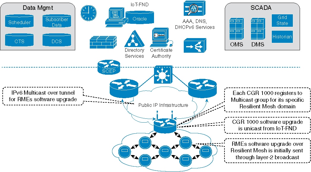
The IPv6 multicast configuration has the following characteristics:
-
IPv6 Multicast is used between the IoT FND or CE and the Cisco Resilient Mesh endpoints when performing:
-
Software upgrade of the endpoints
-
Demand reset messages
-
Demand response messages (there could be more than one group for this per meter)
-
Targeted pings (group of meters on a given feeder, for example)
-
Group of meters with the same read time/cycle
-
-
Each PAN is a multicast group with the unicast-prefix-based multicast address (RFC 3306)
-
The head-end router routes (PIMv6 SSM) all multicast traffic to the unicast-prefix-based multicast address to the CGR (MLDv2)
-
CGR multicast agent receives the multicast
The following guide shows an overview of the Multicast operation in an IPv6 FAN:
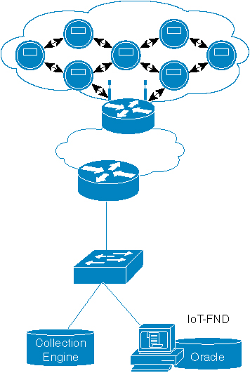
For sample configuration, see Sample Router Configuration.
For more on dot1x, see show dot1x all details.
Forwarding Multicast Traffic
There are two ways to forward multicast traffic to a CGR running Cisco IOS from the head-end:
- Configure the CGR as multicast client where the tunnel is configured with ipv6 mld join-group .
- Enable IPv6 multicast routing on the and configure it as a PIM6 router. This is the preferred method.
Method 1: Configuring MLD on the IPv6 Tunnel Interface
For this method, configure the CGR tunnel interface with MLD as follows:
Router (config)# interface Tunnel100
Router (config-if)# ipv6 mld join-group ff38:40:2001:0db8:beef:cafe:0:1
Note |
In above example, the IP address is constructed from the the IPv6 subnet of WPAN. |
Method 2: Configuring CGR as PIM6 Router
The preferred method of forwarding multicast traffic to the CGR is to enable ipv6 multicast routing on the CGR and configure it as a PIM6 router. Because the unicast-prefix-based multicast address is still needed for WPAN, you must configure it under loopback0 on the CGR, and configure the CGR to become a PIM-neighbor with the ASR head-end.
To configure this method, perform the following steps on the CGR:
SUMMARY STEPS
- Enable IPv6 multicast-routing:
- Configure MLD under the loopback0:
- Configure the IPv6 PIM Rendezvous Point (RP):
DETAILED STEPS
| Step 1 |
Enable IPv6 multicast-routing: Example: |
| Step 2 |
Configure MLD under the loopback0: Example: |
| Step 3 |
Configure the IPv6 PIM Rendezvous Point (RP): Example: |
What to do next
ASR/CSR configuration example:
ipv6 pim rp-address 2001:DB9::1 bidir
ipv6 pim spt-threshold infinity

interface Loopback0
 ipv6 address 2001:DB9::1/128
 ipv6 pim hello-interval 500
ipv6 pim

interface GigabitEthernet0/0/0
ipv6 pim
Configuring Dual-PHY WPAN
Note |
CR-Mesh Release 6.4 does not support Dual-PHY WPAN on CGR. |
This section describes how to configure the Dual-PHY WPAN feature.
Configuring the Dual-PHY Master-Slave Relationship
Follow this procedure to configure master and slave WPANs on a CGR.
Before you begin
-
Do not configure mesh-security keys on the slave WPAN.
-
You must configure mesh-security keys on the master WPAN after the slave WPAN is functionally up.
-
Leave the rpl route poisoning configuration of the slave WPAN unchanged.
-
If you want a Cisco Resilient Mesh node to dynamically switch a connection or PAN between different WPAN interfaces (for example, a DUAL-PHY node dynamically switching between RF and PLC), the master and slave WPAN must have same SSID. This is an optional configuration.
This requirement is so the mesh-side node can see two PHYs as being from the same network (SSID) and can dynamically select either interface. The SSIDs can be different on the WPAN and CGR side.
Note |
Configure master-slave WPANs in the following order; otherwise, the master-slave configuration may not work properly. |
SUMMARY STEPS
- Expire all the mesh-security keys on master and slave WPAN slots.
- Configure both WPANs, slave and master, as if they are two independent WPANs.
- Ensure that you do not enable rpl route-poisoning on any WPANs.
- Determine master and slave nodes, and then configure the following on the slave-slot:
- If network mesh security mode is enabled, configure the mesh-security key(s) on the master slot. The same mesh-key on the slave WPAN module are enabled internally. On the CGR side, the mesh-security key is associated only with the master slot.
- Reload only the slave module.
DETAILED STEPS
| Step 1 |
Expire all the mesh-security keys on master and slave WPAN slots. |
| Step 2 |
Configure both WPANs, slave and master, as if they are two independent WPANs. |
| Step 3 |
Ensure that you do not enable rpl route-poisoning on any WPANs. |
| Step 4 |
Determine master and slave nodes, and then configure the following on the slave-slot: Example: |
| Step 5 |
If network mesh security mode is enabled, configure the mesh-security key(s) on the master slot. The same mesh-key on the slave WPAN module are enabled internally. On the CGR side, the mesh-security key is associated only with the master slot. |
| Step 6 |
Reload only the slave module. |
What to do next
To retain the Dual-PHY master-slave relationship, a CGR requires a sequential reload of first slave and then master WPANs in the following cases, even when the configuration remains unchanged:
-
After reload of master slot WPAN
-
After reload of slave slot WPAN
-
After reload of the CGR
-
After an image upgrade of the CGR and subsequent mandatory reload
Master-Slave WPAN Configuration Example
Dual-PHY can have master and slave for PLC and RF WPAN modules. The IPv6 prefix of the master is used for IPv6 addressing of the nodes.
Router# show running-config interface wpan 4/1
Building configuration...
Current configuration : 471 bytes
!
interface Wpan4/1
 no ip address
 ip broadcast-address 0.0.0.0
 no ip route-cache
 ieee154 beacon-async min-interval 120 max-interval 900 suppression-coefficient 1
 ieee154 panid 7224
 ieee154 ssid migration_far2
 ieee154 txpower -30
 authentication host-mode multi-auth
 authentication port-control auto
 ipv6 address 2092:1:1:1::/64
 ipv6 enable
 ipv6 dhcp relay destination  2010:A0B0:1001:22::2
 dot1x pae authenticator
 mesh-security mesh-key lifetime 259200
end

Router# show running-config interface wpan 5/1
Building configuration...
Current configuration : 481 bytes
!
interface Wpan5/1
 no ip address
 ip broadcast-address 0.0.0.0
 no ip route-cache
 ieee154 beacon-async min-interval 120 max-interval 900 suppression-coefficient 1
 ieee154 panid 7215
 ieee154 ssid plc123
 slave-mode 4
 rpl dag-lifetime 240
 rpl dio-min 21
 rpl version-incr-time 240
 authentication host-mode multi-auth
 authentication port-control auto
 ipv6 address 2091:1:1:1::/64
 ipv6 enable
 ipv6 dhcp relay destination  2010:A0B0:1001:22::2
 dot1x pae authenticator
end
Router#
show commands for Master-Slave WPANs
You can use the following show wpan commands to trace nodes in a Dual-PHY master-slave configuration:
-
show wpan <master slot >/1 rpl itable —Shows information for the actual slot from which RPL DAOs originated.
-
show wpan <master slot >/1 rpl stable —Shows slave slot information for the actual slot from which RPL DAOs originated.
-
show wpan <master slot >/1 rpl stree —Shows the link type (or slave slot information) for each node in the RPL tree.
-
show wpan <master slot >/1 eap-table —Shows slave slot information for the actual slot from which IEEE802.1x traffic originated.
-
All configurations and show commands related to the physical layer or the WPAN module hardware remain as is; show wpan <slot >/1 hardware * remains the same, per the actual physical slot.
Router# show wpan 4/1 link-neighbors table
------------------------- WPAN LINK NEIGHBOR TABLE [4] -------------------------
EUI64                   RSSIF   RSSIR   LQIF    LQIR    FIRST_HEARD   LAST_HEARD
00078108003C2200        -70     -78     58      9       12:02:18      14:08:02
00078108003C2201        n/a     -75     n/a     18      13:05:15      13:53:48
00078108003C2202        -72     -74     35      64      11:51:40      14:06:09
00078108003C2203        -73     -76     9       17      11:51:55      14:07:28
00078108003C2204        -71     -75     35      23      12:02:34      14:01:45
00078108003C2205        -74     -77     18      16      12:02:12      14:06:04
00078108003C2206        -73     -74     19      26      12:02:08      14:08:12
00078108003C2207        -72     -70     15      75      13:04:39      14:03:56
00078108003C2209        -73     -77     45      36      11:58:20      14:02:20
00078108003C220A        -74     -75     5       27      12:13:40      14:07:48
Number of Entries in WPAN LINK NEIGHBOR TABLE: 10
Router# show wpan 5/1 link-neighbors table
-------------------------------------------------------------------------------- WPAN LINK NEIGHBOR TABLE [5] --------------------------------------------------------------------------------
EUI64                   RSSIF   RSSIR   LQIF    LQIR    MODF    MODR    TXGAINF TXGAINR TXRESF  TXRESR  TMF     TMR     TXCOEFFF   TXCOEFFR        DPHASE  APHASE  LOCKF LOCKR   LAST_HEARD
000781FE0000012C        114     114     95      95      D8PSK   D8PSK   1       1       6       6       1F      3F      0000FFFFFFFF       0000FFFFFFFF    3       5       0     0       14:05:00
000781FE0000012D        114     114     96      96      D8PSK   D8PSK   1       1       6       6       3F      3F      0000FFFFFFFF       0000FFFFFFFF    3       5       0     0       13:55:54
000781FE0000012E        114     114     104     104     D8PSK   D8PSK   1       1       6       6       3F      3F      0000FFFFFFFF       0000FFFFFFFF    3       5       0     0       14:08:39
000781FE0000012F        114     114     120     120     D8PSK   D8PSK   1       1       6       6       3F      3F      0000FFFFFFFF       0000FFFFFFFF    3       5       0     0       14:07:15
000781FE00000130        114     114     101     101     D8PSK   D8PSK   1       1       6       6       1F      3F      0000FFFFFFFF       0000FFFFFFFF    3       5       0     0       13:59:39
Number of Entries in WPAN LINK NEIGHBOR TABLE: 5
Router#
Router#
Router# show wpan 4/1 rpl table
-------------------------------- WPAN RPL ROUTE TABLE [4] --------------------------------
NODE_IPADDR                             NEXTHOP_IP                              LAST_HEARD
2092:1:1:1:AAAA:8108:3C:2200            2092:1:1:1:AAAA:8108:3C:2203            13:47:54
2092:1:1:1:AAAA:8108:3C:2201            2092:1:1:1:AAAA:8108:3C:2204            13:45:25
2092:1:1:1:AAAA:8108:3C:2202            2092:1:1:1::                            13:48:53
2092:1:1:1:AAAA:8108:3C:2203            2092:1:1:1::                            13:49:42
2092:1:1:1:AAAA:8108:3C:2204            2092:1:1:1::                            13:44:41
2092:1:1:1:AAAA:8108:3C:2205            2092:1:1:1::                            13:58:26
2092:1:1:1:AAAA:8108:3C:2206            2092:1:1:1::                            13:58:15
2092:1:1:1:AAAA:8108:3C:2209            2092:1:1:1::                            14:01:42
2092:1:1:1:AAAA:8108:3C:220A            2092:1:1:1::                            13:57:39
2092:1:1:1:AAAA:8108:3C:2300            2092:1:1:1:AAAA:8108:3C:2206            14:05:12
2092:1:1:1:AAAA:8108:3C:2301            2092:1:1:1:AAAA:8108:3C:2206            13:37:31
<!---snip--!>
2092:1:1:1:AAAA:8108:3C:240A            2092:1:1:1:AAAA:8108:3C:2303            14:03:54
2092:1:1:1:AAAA:8108:3C:240B            2092:1:1:1:AAAA:8108:3C:2301            13:35:32
2092:1:1:1:AAAA:81FE:0:12C              2092:1:1:1::                            13:51:17
2092:1:1:1:AAAA:81FE:0:12D              2092:1:1:1::                            13:55:54
2092:1:1:1:AAAA:81FE:0:12E              2092:1:1:1::                            14:01:06
2092:1:1:1:AAAA:81FE:0:12F              2092:1:1:1::                            13:53:45
2092:1:1:1:AAAA:81FE:0:130              2092:1:1:1::                            13:59:39
Number of Entries in WPAN RPL ROUTE TABLE: 36
Router#
Router#
Router# show wpan 4/1 rpl itable
----------------------------- WPAN RPL IPROUTE INFO TABLE [4] -----------------------------
NODE_IPADDR                             RANK    VERSION NEXTHOP_IP                              ETX_P   ETX_L   RSSIR   RSSIF      HOPS    PARENTS SSLOT
2092:1:1:1:AAAA:8108:3C:2200            523     4       2092:1:1:1:AAAA:8108:3C:2203            263     256     -50     -512       3       4
2092:1:1:1:AAAA:8108:3C:2201            527     3       2092:1:1:1:AAAA:8108:3C:2203            265     256     -47     -562       3       4
2092:1:1:1:AAAA:8108:3C:2202            333     4       2092:1:1:1::                            0       333     -77     -771       3       4
2092:1:1:1:AAAA:8108:3C:2203            269     4       2092:1:1:1::                            0       265     -70     -721       1       4
2092:1:1:1:AAAA:8108:3C:2204            290     4       2092:1:1:1::                            0       285     -70     -731       2       4
2092:1:1:1:AAAA:8108:3C:2205            292     4       2092:1:1:1::                            0       287     -72     -721       3       4
2092:1:1:1:AAAA:8108:3C:2206            256     4       2092:1:1:1::                            0       256     -74     -751       1       4
2092:1:1:1:AAAA:8108:3C:2209            366     4       2092:1:1:1::                            0       352     -71     -761       3       4
2092:1:1:1:AAAA:8108:3C:220A            345     4       2092:1:1:1::                            0       345     -73     -751       3       4
2092:1:1:1:AAAA:8108:3C:2300            512     4       2092:1:1:1:AAAA:8108:3C:2206            258     256     -72     -692       3       4
2092:1:1:1:AAAA:8108:3C:2301            512     4       2092:1:1:1:AAAA:8108:3C:2206            258     256     -76     -782       3       4
<!---truncated--!>
2092:1:1:1:AAAA:81FE:0:12C              302     4       2092:1:1:1::                            0       291     116     1161       1       5
2092:1:1:1:AAAA:81FE:0:12D              309     4       2092:1:1:1::                            0       302     116     1161       2       5
2092:1:1:1:AAAA:81FE:0:12E              331     4       2092:1:1:1::                            0       321     116     1161       3       5
2092:1:1:1:AAAA:81FE:0:12F              348     4       2092:1:1:1::                            0       336     116     1161       3       5
2092:1:1:1:AAAA:81FE:0:130              342     4       2092:1:1:1::                            0       321     116     1161       3       5
Number of Entries in WPAN RPL IPROUTE INFO TABLE: 36
Router#
Router# show wpan 4/1 rpl stable
------------------------------ WPAN RPL ROUTE SLOT TABLE [4] ------------------------------
NODE_IPADDR                             NEXTHOP_IP                              SSLOT   LAST_HEARD
2092:1:1:1:AAAA:8108:3C:2200            2092:1:1:1:AAAA:8108:3C:2203            4       15:12:29
2092:1:1:1:AAAA:8108:3C:2201            2092:1:1:1:AAAA:8108:3C:2203            4       14:43:10
2092:1:1:1:AAAA:8108:3C:2202            2092:1:1:1::                            4       15:16:55
2092:1:1:1:AAAA:8108:3C:2203            2092:1:1:1::                            4       15:13:21
2092:1:1:1:AAAA:8108:3C:2204            2092:1:1:1::                            4       14:48:37
2092:1:1:1:AAAA:8108:3C:2205            2092:1:1:1::                            4       15:05:00
2092:1:1:1:AAAA:8108:3C:2206            2092:1:1:1::                            4       15:01:05
2092:1:1:1:AAAA:8108:3C:2209            2092:1:1:1::                            4       15:06:11
2092:1:1:1:AAAA:8108:3C:220A            2092:1:1:1::                            4       14:58:23
2092:1:1:1:AAAA:8108:3C:2300            2092:1:1:1:AAAA:8108:3C:2206            4       15:05:55
2092:1:1:1:AAAA:8108:3C:2301            2092:1:1:1:AAAA:8108:3C:2206            4       15:04:19
2092:1:1:1:AAAA:8108:3C:2302            2092:1:1:1:AAAA:8108:3C:2206            4       14:56:48
<!---snip--!>
2092:1:1:1:AAAA:81FE:0:12C              2092:1:1:1::                            5       14:53:32
2092:1:1:1:AAAA:81FE:0:12D              2092:1:1:1::                            5       14:50:57
2092:1:1:1:AAAA:81FE:0:12E              2092:1:1:1::                            5       15:06:24
2092:1:1:1:AAAA:81FE:0:12F              2092:1:1:1::                            5       15:15:45
2092:1:1:1:AAAA:81FE:0:130              2092:1:1:1::                            5       15:03:24
Number of Entries in WPAN RPL ROUTE SLOT TABLE: 36 (external 0) (RF 31) (PLC 5)

Router# show wpan 4/1 rpl stree
----------------------------- WPAN RPL SLOT TREE [4] -----------------------------
  [2092:1:1:1::]
           \--(RF )-- 2092:1:1:1:AAAA:8108:3C:2202
           \--(RF )-- 2092:1:1:1:AAAA:8108:3C:2203
                   \--(RF )-- 2092:1:1:1:AAAA:8108:3C:2200
                   \--(RF )-- 2092:1:1:1:AAAA:8108:3C:2201
           \--(RF )-- 2092:1:1:1:AAAA:8108:3C:2204
           \--(RF )-- 2092:1:1:1:AAAA:8108:3C:2205
           \--(RF )-- 2092:1:1:1:AAAA:8108:3C:2206
                   \--(RF )-- 2092:1:1:1:AAAA:8108:3C:2300
                   \--(RF )-- 2092:1:1:1:AAAA:8108:3C:2301
                           \--(RF )-- 2092:1:1:1:AAAA:8108:3C:2406
                           \--(RF )-- 2092:1:1:1:AAAA:8108:3C:2408
                   \--(RF )-- 2092:1:1:1:AAAA:8108:3C:2302
                   \--(RF )-- 2092:1:1:1:AAAA:8108:3C:2303
                           \--(RF )-- 2092:1:1:1:AAAA:8108:3C:2407
                           \--(RF )-- 2092:1:1:1:AAAA:8108:3C:240A
                   \--(RF )-- 2092:1:1:1:AAAA:8108:3C:2304
                           \--(RF )-- 2092:1:1:1:AAAA:8108:3C:2400
                           \--(RF )-- 2092:1:1:1:AAAA:8108:3C:2403
                           \--(RF )-- 2092:1:1:1:AAAA:8108:3C:2404
                   \--(RF )-- 2092:1:1:1:AAAA:8108:3C:2305
                   \--(RF )-- 2092:1:1:1:AAAA:8108:3C:2307
                           \--(RF )-- 2092:1:1:1:AAAA:8108:3C:2402
                           \--(RF )-- 2092:1:1:1:AAAA:8108:3C:2405
                   \--(RF )-- 2092:1:1:1:AAAA:8108:3C:2308
                   \--(RF )-- 2092:1:1:1:AAAA:8108:3C:2309
                           \--(RF )-- 2092:1:1:1:AAAA:8108:3C:240B
                   \--(RF )-- 2092:1:1:1:AAAA:8108:3C:230A
                   \--(RF )-- 2092:1:1:1:AAAA:8108:3C:230B
                           \--(RF )-- 2092:1:1:1:AAAA:8108:3C:2409
           \--(RF )-- 2092:1:1:1:AAAA:8108:3C:2209
           \--(RF )-- 2092:1:1:1:AAAA:8108:3C:220A
           \--(PLC)-- 2092:1:1:1:AAAA:81FE:0:12C
           \--(PLC)-- 2092:1:1:1:AAAA:81FE:0:12D
           \--(PLC)-- 2092:1:1:1:AAAA:81FE:0:12E
           \--(PLC)-- 2092:1:1:1:AAAA:81FE:0:12F
           \--(PLC)-- 2092:1:1:1:AAAA:81FE:0:130
RPL SLOT TREE: Num.DataEntries 36, Num.GraphNodes 37 (external 0) (RF 31) (PLC 5)
Removing the Dual-PHY Master-Slave WPAN Configuration
This section describes how to remove the Dual-PHY master-slave relationship on a WPAN.
Before you begin
-
Use show wpan 5/1 config to verify that the slave module is currently configured as slave.
-
If the slave WPAN does not already have an IPv6 prefix assigned, assign a new IPv6 prefix while still in slave mode; for example, ipv6 address 2091:1:1:1::/64 .
-
Use show mesh-security keys to verify that the slave module has no mesh-security keys configured. (See detailed CLI output below.)
To remove an existing master-slave relationship between two WPANs, follow this procedure in exactly the sequence shown. The example in this procedure uses WPAN 4/1 as master and WPAN 5/1 as slave.
SUMMARY STEPS
- From the interface config mode of the slave WPAN, enter no slave-mode <master-slot-number >:
- Reload the slave module by powering off and then powering on:
- Add mesh-security keys for the slaves. (The slave module should not have its own mesh-security keys when in the master-slave relationship.)
- Check the status of the WPAN previously configured as slave using the following commands:
DETAILED STEPS
| Step 1 |
From the interface config mode of the slave WPAN, enter no slave-mode <master-slot-number >: Example: |
| Step 2 |
Reload the slave module by powering off and then powering on: Example:Wait for WPAN power down messages, and then wait another 60-90 seconds. Then, power up the module: Example:Wait for WPAN power on messages, and then wait another 60-90 seconds before proceeding. |
| Step 3 |
Add mesh-security keys for the slaves. (The slave module should not have its own mesh-security keys when in the master-slave relationship.) Example:You can add up to four mesh-keys for the WPAN slot. |
| Step 4 |
Check the status of the WPAN previously configured as slave using the following commands: Example:See Removing Master-Slave Relationship Configuration Example for sample command output. |
Removing Master-Slave Relationship Configuration Example
This section shows example output from the commands to remove the master-slave relationship between two CGR WPAN modules. In this example, the master WPAN module is in slot 4, and the slave WPAN module is in slot 5.
Checking Existing Configuration of the Master and Slave Modules
Router# show run interface wpan 4/1
!<<<<<---- #Initially configured as master WPAN
Building configuration...
Current configuration : 471 bytes
!
interface Wpan4/1
no ip address
ip broadcast-address 0.0.0.0
no ip route-cache
ieee154 beacon-async min-interval 120 max-interval 900 suppression-coefficient 1
ieee154 panid 7224
ieee154 ssid migration_far2
ieee154 txpower -30
authentication host-mode multi-auth
authentication port-control auto
ipv6 address 2092:1:1:1::/64
ipv6 enable
ipv6 dhcp relay destination 2010:A0B0:1001:22::2
dot1x pae authenticator
mesh-security mesh-key lifetime 259200
end
Router# show run interface wpan 5/1
!<<<<<---- #Initially configured as slave
Building configuration...
Current configuration : 481 bytes
!
interface Wpan5/1
no ip address
ip broadcast-address 0.0.0.0
no ip route-cache
ieee154 beacon-async min-interval 120 max-interval 900 suppression-coefficient 1
ieee154 panid 7215
ieee154 ssid plc123
slave-mode 4
!<<<<---- #WPAN 5/1 has a master WPAN in slot 4
rpl dag-lifetime 240
rpl dio-min 21
rpl version-incr-time 240
authentication host-mode multi-auth
authentication port-control auto
ipv6 address 2091:1:1:1::/64
ipv6 enable
ipv6 dhcp relay destination 2010:A0B0:1001:22::2
dot1x pae authenticator
end
Check configuration of the slave module where slave mode displays the master-slot number as shown below:
Router# show wpan 5/1 config
module type: PLC-WPAN (IEEE P1901.2 PLC)
ssid: plc123
panid: 7215
transmit power: 32
ref-phase: 1
tonemap: unlocked (not used)
phy_params: 1 (ceneleca) 000000000FFFFFFFFF
beacon async: min-interval 120 max-interval 900 suppression-coefficient 1
security mode: 1
test mode: 0 (test firmware only)
admin_status: up
rpl prefix: 2091:1:1:1::/64
rpl route-poisoning: off
rpl dodag-lifetime: 240
rpl dio-dbl: 0
rpl dio-min: 21
rpl version-incr-time: 240
detach bridge: no
bootloader mode: no
mcast-agent: FF38:40:2091:1:1:1:0:1 61624 1153
firmware version: 5.5.48
slave mode: 4
(slot 5 is attached to master slot 4)
Removing Slave Mode from Slave WPAN Configuration
Router#conf t
Enter configuration commands, one per line. End with CNTL/Z.
Router(config)# interface wpan 5/1
Router(config-if)# no slave-mode 4
!<<<<<---- #Ends slave mode to master-slot 4
Router(config-if)# end
Router#
Reloading the Slave WPAN
Router(config)# hw poweroff 5
Router(config)#
*May 22 12:42:15.511 PST: %CGR1K_SYS-5-MODULE_POWER_DOWN: Module in slot 5 is powered down.
Router(config)#
*May 22 12:42:17.539 PST: %LINK-3-UPDOWN: Interface Wpan5/1, changed state to down
*May 22 12:42:18.539 PST: %LINEPROTO-5-UPDOWN: Line protocol on Interface Wpan5/1, changed state to down
Router(config)#
Router(config)# no hw poweroff 5
*May 22 12:43:38.763 PST: %CGR1K_SYS-5-MODULE_POWER_UP: Module in slot 5 is powered up.
Router(config)#
*May 22 12:43:56.591 PST: %LINK-3-UPDOWN: Interface Wpan5/1, changed state to up
*May 22 12:43:57.591 PST: %LINEPROTO-5-UPDOWN: Line protocol on Interface Wpan5/1, changed state to up
Router(config)# end
Adding Mesh-Security keys for WPAN 5/1
Router# mesh-security set mesh-key interface wpan 5/1 key 5551
Key ID       : 0
Key expiry   : Sat Jun 21 12:55:43 2014
Router# mesh-security set mesh-key interface wpan 5/1 key 5552
Key ID       : 1
Key expiry   : Mon Jul 21 12:55:43 2014
Note |
There can be up to four mesh-security keys configured for a WPAN slot. |
Verifying that the WPAN is no Longer Configured as Slave
Router# show run interface wpan 5/1
Building configuration...
Current configuration : 467 bytes
!
interface Wpan5/1
 no ip address
 ip broadcast-address 0.0.0.0
 no ip route-cache
 ieee154 beacon-async min-interval 120 max-interval 900 suppression-coefficient 1
 ieee154 panid 7215
 ieee154 ssid plc123
 rpl dag-lifetime 240
 rpl dio-min 21
 rpl version-incr-time 240
 authentication host-mode multi-auth
 authentication port-control auto
 ipv6 address 2091:1:1:1::/64
 ipv6 enable
 ipv6 dhcp relay destination  2010:A0B0:1001:22::2
 dot1x pae authenticator
end
Router#
Router# show wpan 5/1 config
module type:    PLC-WPAN (IEEE P1901.2 PLC)
ssid:           plc123
panid:          7215
transmit power: 32
ref-phase:      1
tonemap:        unlocked (not used)
phy_params:     1 (ceneleca) 000000000FFFFFFFFF
beacon async:   min-interval 120 max-interval 900 suppression-coefficient 1
security mode:  1
test mode:      0 (test firmware only)
admin_status:   up
rpl prefix:            2091:1:1:1::/64
rpl route-poisoning:   off
rpl dodag-lifetime:    240
rpl dio-dbl:           0
rpl dio-min:           21
rpl version-incr-time: 240
detach bridge:         no
bootloader mode:       no
mcast-agent:           FF38:40:2091:1:1:1:0:1 61624 1153
firmware version:      5.5.48
slave mode:            no
Router#
Router# show mesh-security keys
Mesh Interface: Wpan4/1
Master Key Lifetime  : 12 Days 0 Hours 0 Minutes 0 Seconds
Temporal Key Lifetime: 6 Days 0 Hours 0 Minutes 0 Seconds
Mesh Key Lifetime    : 3 Days 0 Hours 0 Minutes 0 Seconds
Key ID         : 0 *
Key expiry     : Sat May 24 11:51:35 2014
Time remaining : 1 Days 22 Hours 55 Minutes 39 Seconds
Key ID         : 1
Key expiry     : Tue May 27 11:51:35 2014
Time remaining : 4 Days 22 Hours 55 Minutes 39 Seconds
Key ID         : 2
Key expiry     : Fri May 30 11:51:35 2014
Time remaining : 7 Days 22 Hours 55 Minutes 39 Seconds
Key ID         : 3
Key expiry     : Mon Jun  2 11:51:35 2014
Time remaining : 10 Days 22 Hours 55 Minutes 39 Seconds
Mesh Interface: Wpan5/1
Master Key Lifetime  : 120 Days 0 Hours 0 Minutes 0 Seconds
Temporal Key Lifetime: 60 Days 0 Hours 0 Minutes 0 Seconds
Mesh Key Lifetime    : 30 Days 0 Hours 0 Minutes 0 Seconds
Key ID         : 0 *
Key expiry     : Sat Jun 21 12:55:43 2014
Time remaining : 29 Days 23 Hours 59 Minutes 47 Seconds
Key ID         : 1
Key expiry     : Mon Jul 21 12:55:43 2014
Time remaining : 59 Days 23 Hours 59 Minutes 47 Seconds
Router#
Verifying that WPAN 5/1 Forms Own RPL Table
Router# show wpan 5/1 rpl table

-------------------------------- WPAN RPL ROUTE TABLE [5] --------------------------------
NODE_IPADDR					NEXTHOP_IP			LAST_HEARD
2091:1:1:1:AAAA:81FE:0:12C			2091:1:1:1::			13:42:17
2091:1:1:1:AAAA:81FE:0:12D			2091:1:1:1::			13:40:47
2091:1:1:1:AAAA:81FE:0:12F			2091:1:1:1::			13:41:59
Number of Entries in WPAN RPL ROUTE TABLE: 3
Notice above RMEs showing IPv6 address based on the WPAN 5/1 prefix.
Router# show wpan 5/1 rpl stable
------------------------------ WPAN RPL ROUTE SLOT TABLE [5] ------------------------------
NODE_IPADDR					NEXTHOP_IP		SSLOT		LAST_HEARD
2091:1:1:1:AAAA:81FE:0:12C			2091:1:1:1::	5	13:42:17
2091:1:1:1:AAAA:81FE:0:12D			2091:1:1:1::	5	13:40:47
2091:1:1:1:AAAA:81FE:0:12F			2091:1:1:1::	5	13:41:59
Number of Entries in WPAN RPL ROUTE SLOT TABLE: 3 (external 0) (RF 0) (PLC 3)
Notice above RMEs showing slot 5 for the WPAN 5/1.
Verifying the IPv6 Path to WPAN 5/1 Nodes
Router# ping 2091:1:1:1:AAAA:81FE:0:12C

Type escape sequence to abort.
Sending 5, 100-byte ICMP Echos to 2091:1:1:1:AAAA:81FE:0:12C, timeout is 2 seconds:
!!!!!
Success rate is 100 percent (5/5), round-trip min/avg/max = 256/268/276 ms
Router#
Configuring DTLS Relay for EST
The Cisco Resilient Mesh uses EST over CoAP/DTLS/UDP for certificate enrollment. During the initial bootstrapping process, nodes that have already joined the network (enrolled and authenticated) act as DTLS relays for nodes being bootstrapped.
Use the following command to configure DTLS relay:
CGR#configure terminal
CGR(config)#interface wpan 4/1

CGR(config-if)#dtls-relay ?
X:X:X:X::X   IPv6 address (aaaa:bbbb:cccc:dddd:eeee:ffff:gggg:hhhh, aaaa::bbb)

CGR(config-if)#dtls-relay 2060:FACD::6 ?
lifetime     specify session lifetime
max-sessions specify maximum number of sessions
port         destination port
Example
CGR(config-if)#dtls-relay 2060:FACD::6 port 61629 max-sessions 10 lifetime 300
Use the following show command to verify the configuration:
#show wpan 4/1 config
Module Type: RF-WPAN (IEEE 802.15.4e/g RF OFDM)
ssid: 510P1-lzhao3
panid: 925
phy_mode: 149
band-id: 4
transmit power: 15
channel: 254
dwell: window 12400 max-dwell 400
fec: n/a
beacon async: min-interval 15 max-interval 60 suppression-coefficient 1
security mode: 1
test mode: 0 (test firmware only)
admin_status: up
rpl prefix: 2022:AAAA::10/64
rpl route-poisoning: off
rpl dodag-lifetime: 15
rpl dio-dbl: 1
rpl dio-min: 14
rpl version-incr-time: 10
detach bridge: no
bootloader mode: no
mcast-agent: FF38:40:2022:AAAA::1 61624 61628 1153
firmware version: 6.1(6.1.27)
slave mode: no
wisun mode: no
ieee154 beacon ver incr time: 60 seconds
DTLS Relay: 2060:FACD::6 max-sessions 10 lifetime 300
Configuring Wi-SUN Mode
Wi-SUN mode is supported from Cisco Resilient Mesh Release 6.1.
Note |
Cisco Resilient Mesh Release 6.3 only supports Wi-SUN mode. |
To enable Wi-SUN mode, use the following comand under interface configuration mode:
(config-if)#wisun-modeNote |
|
You can change ucast dwell, bcast dwell, and bcast interval by using the following command under WPAN interface. If not configured, all the parameters will keep the default values.
(config-if)#ieee154 wisun-dwell ucast-dwell-int <125> bcast-dwell-int <125> bcast-int <500>When CGR is in Wi-SUN mode, if there are nodes in the WPAN route table and route poisoning is not enabled, changing PANID will enable temporary RPL poisoning. It will be disabled automatically. The new panid will take affect after 3 DIO messages are sent.
Verifying Connectivity to the CGR
To verify connectivity to the CGR before querying the system, use the ping command in EXEC mode:
# Router# ping ?
  WORD      Ping destination address or hostname
  atm       ATM echo
  clns      CLNS echo
  ethernet  Ethernet echo
  ip        IP echo
  ipv6      IPv6 echo
  mpls      MPLS echo
  sna       SNA APING transaction program
  srb       srb echo
  tag       Tag encapsulated IP echo
  <cr>
To discover the routes that packets will actually take when traveling to their destination across an IPv6 network, use the traceroute ipv6 command in EXEC mode.
# traceroute ipv6 [host-name |ip-address ]
show Command Examples
Use the following command to view all WPAN show commands:
Router# show wpan 4/1 ?
  config             Configuration information
  data-rate          Data rate during last 1 minute
  eap-table          Recent EAP node table
  hardware           Hardware information
  ieee154            IEEE 802.15.4 related information
  ieeep19012         IEEE P1901.2 related information
  link-neighbors     Layer 3 link neighbor information
  module-type        Module type (RF or PLC)
  oui-table          OUI mapping table for 8-to-6 MAC address translation
                     (EUI64 <-->IEEE MAC)
  outage-server      WPAN outage server
  outage-table       WPAN outage table
  packet-count       Packet counts
  restoration-table  WPAN restoration table
  rpl                RPL related information
  service-state      WPAN service state
  slave-mode         Slave mode
This section covers the following RPL and WPAN show commands:
show wpan config
Router# show wpan 4/1 config
module type:    RF-WPAN (IEEE 802.15.4e/g RF 900MHz)
ssid:           migration_far2     <-- #See Naming the SSID.
panid:          7224               <-- #See Naming Your PAN.
transmit power: -30                <-- #See Configuring Transmit Power.
channel:        254                <-- #Channel hopping setting
dwell:          window 20000 max-dwell 400
beacon async:   min-interval 120 max-interval 900 suppression-coefficient 1
security mode:  1
test mode:      0 (test firmware only)
admin_status:   up
rpl prefix:            2092:1:1:1::/64
rpl route-poisoning:   off
rpl dodag-lifetime:    120
rpl dio-dbl:           0
rpl dio-min:           20
rpl version-incr-time: 60
detach bridge:         no
bootloader mode:       no
mcast-agent:           FF38:40:2092:1:1:1:0:1 61624 1153
firmware version:      5.5.48
slave mode:            no
show wpan hardware
To view the WPAN configuration that resides on the WPAN hardware, use the show wpan <slot >/1 hardware configuration command:
Router# show wpan 4/1 hardware hwversion
hardware version: Itron OWCM
Hardware rev : 3.1
Model name   : OWCM
Hardware ID  : RFLAN/3.60/3.80
Router# show wpan 4/1 hardware version
firmware version: 5.5.48, apps/bridge, master, 4b89e37, Apr  4
Router# show wpan 4/1 hardware config
serial number:  FF-FF-FF-FF-FF-FF-FF-FF
eui64:          000781080067B074
ssid:           migration_far2
panid:          7224
transmit power: -30  (<-txpower_reg 0x12)
channel:        254
channel notch:  none
dwell:          window 20000 max-dwell 400
beacon async:   min-interval 120 max-interval 900 suppression-coefficient 1
security mode:  1
admin_status:   up
Other show wpan hardware options are:
Router# show wpan 4/1 hardware ?
  channel-list      Channel list
  config            Configuration
  debug             Debug information
  global-time       Global time
  hwversion         Hardware version
  key-info          Mesh key information
  leds              LED status
  link-neighbors    Layer 2 link neighbor information
  link-stats        Link statistics
  network-if-stats  Network interface statistics
  security-mode     Security mode (enabled by dot1x)
  test-mode         Test mode (for test firmware only)
  uptime            Uptime
  version           Firmware version
The output of the command show wpan <slot >/1 hardware key shows mesh-security keys (GTKs) that reside on the WPAN hardware. The show wpan <slot >/1 hardware key output should agree with the output of show mesh-security-keys . (See show mesh-security keys.)
Router# show wpan 4/1 hard key
keyinfo:
        key 0: valid *
        key 1: valid
        key 2: empty
        key 3: empty
        key x: valid
The show wpan <slot >/1 hardware link-neighbor command shows the list of recently heard IEEE 802.15.4 link neighbors. These link neighbors are RMEs within a 1-hop transmit range from the CGR and from which the CGR has recently heard IEEE 802.15.4 frames. The list shows only the most recently heard subset from all possible 1-hop neighbors.
Router# show wpan 4/1 hardware link-neighbors
eui64                 heard   etx     sent / ack    rssif / rssir   lqif / lqir
0007810800A909A1      5       65535      0 / 0        n/a / -99      n/a / 41
0007810800CBF246      23      65535      0 / 0        n/a / -86      n/a / 76
0007810800000001      38      65535      0 / 0        n/a / -114     n/a / 127
00078108003C2206      59      263        3 / 3       - 71 / -74       36 / 14
00078108003C2202      65      278        0 / 0       - 71 / -77       72 / 36
00078108003C2207      113     258        1 / 1       - 71 / -76       14 / 18

Router# show wpan 4/1 hardware link-stats ?
  bridge          Link statistics bridge
  brief           Link statistics brief
  ieee154-beacon  Link statistics ieee154 beacon
  ieee154-device  Link statistics ieee154 device
  ieee154-mac     Link statistics ieee154 mac
  lowpan          Link statistics lowpan
  radio           Link statistics radio

Router# show wpan 4/1 hardware link-stats brief
linkstats info:
---------------
lowpan
  tx frames: 5244  (1349356 bytes)
  rx frames: 2483  (740228 bytes)
  tx errors: 0
  rx errors: 0
  tx discards: 113
  rx discards: 22
serial
  tx frames: 2340  (250602 bytes)
  rx frames: 1031  (308456 bytes)
  tx errors: 0
  rx errors: 3
  tx discards: 0
  rx discards: 0
show wpan packet-count
Router# show wpan 4/1 packet-count
TOTAL:
        incoming: 940        (183959   bytes)
        outgoing: 739        (192452   bytes)
-------------------------------------------------
lowpan:
        incoming: 395        (81660    bytes)
        outgoing: 79         (11483    bytes)
dot1x:
        incoming: 545        (102299   bytes)
        outgoing: 660        (180969   bytes)
outage:
        incoming: 0          (0        bytes)
restoration:
        incoming: 0          (0        bytes)
-------------------------------------------------
lowpan.icmp:
        incoming: 143        (16601    bytes)
         rpl dao: 41         (7160     bytes)
         rpl dio: 38         (4125     bytes)
         rpl dis: 0          (0        bytes)
         nd ns  : 39         (2816     bytes)
        outgoing: 40         (4000     bytes)
         rpl ra : 0          (0        bytes)
         nd rs  : 0          (0        bytes)
lowpan.dhcp:
        incoming: 179        (23850    bytes)
        outgoing: 27         (6595     bytes)
lowpan.csmp:
        incoming: 73         (41209    bytes)
         - mcast: 0          (0        bytes)
         - ucast: 73         (41209    bytes)
        outgoing: 1          (52       bytes)
         - mcast: 0          (0        bytes)
         - ucast: 1          (52       bytes)
lowpan.c1222:
        incoming: 0          (0        bytes)
         - mcast: 0          (0        bytes)
         - ucast: 0          (0        bytes)
        outgoing: 0          (0        bytes)
         - mcast: 0          (0        bytes)
         - ucast: 0          (0        bytes)
lowpan.other_udp:
        incoming: 0          (0        bytes)
        outgoing: 0          (0        bytes)
lowpan.tcp:
        incoming: 0          (0        bytes)
        outgoing: 0          (0        bytes)
lowpan.other_ip:
        incoming: 0          (0        bytes)
        outgoing: 11         (836      bytes)
-------------------------------------------------
ucast:
        incoming: 902        (179834   bytes)
        outgoing: 728        (191616   bytes)
mcast:
        incoming: 0          (0        bytes)
        outgoing: 0          (0        bytes)
bcast:
        incoming: 38         (4125     bytes)
        outgoing: 11         (836      bytes)
-------------------------------------------------
bridge:
        incoming: 0          (0        bytes)
        outgoing: 0          (0        bytes)
-------------------------------------------------
(ios):
        incoming: 792        (169418   bytes)
        outgoing: 861        (155858   bytes)
(hdlc):
        incoming: 2131       (216892   bytes)
        outgoing: 972        (306238   bytes)
-------------------------------------------------
udp checksum error:
        incoming: 0          (0        bytes)
icmp checksum error:
        incoming: 0          (0        bytes)
tcp checksum error:
        incoming: 0          (0        bytes)
-------------------------------------------------
queue overflow:
        hdlc queue: 0           hold queue: 0
Router#
show wpan link-neighbors
The command show wpan link-neighbors shows the information about the WPAN link neighbors. These link neighbors are RMEs within a 1-hop transmit range from the CGR that sent at least one IPv6 or IEEE 802.1X packet to the CGR during the last hour.
Router# show wpan 4/1 link-neighbors table
------------------------- WPAN LINK NEIGHBOR TABLE [4] -------------------------
EUI64                   RSSIF   RSSIR   LQIF    LQIR    FIRST_HEARD   LAST_HEARD
00078108003C2200        -69     -76     51      7       15:09:50      16:38:17
00078108003C2201        -72     -77     29      14      14:46:01      16:39:57
00078108003C2202        -71     -77     72      21      14:51:32      16:51:14
00078108003C2203        -70     -74     57      10      14:49:31      16:45:44
00078108003C2204        -74     -75     8       14      15:09:39      16:49:39
00078108003C2205        -70     -76     76      15      14:45:01      16:35:16
00078108003C2206        -71     -75     36      20      15:09:44      16:50:37
00078108003C2207        -71     -75     14      16      14:46:25      16:37:48
00078108003C2208        -71     -78     47      7       14:52:51      16:44:15
00078108003C2209        -73     -78     66      15      15:13:34      16:51:16
00078108003C220A        -72     -76     18      14      14:51:51      16:49:21
00078108003C220B        -69     -76     45      9       15:09:37      16:47:55
Number of Entries in WPAN LINK NEIGHBOR TABLE: 12

Router# show wpan 4/1 link-neighbors brief
Number of Entries:      12
Last Reset:     2014:05:18-14:43:33
First Heard:    2014:05:18-14:45:01     00078108003C2205     -76    -70
Last Joined:    2014:05:18-15:13:34     00078108003C2209     -80    -73
Last Heard:     2014:05:18-16:58:54     00078108003C2208     -75    -71
Note |
The minimum RSSI to join a mesh network is -95 dBm; a lower RSSIF/RRSIR value will not allow the node to establish connectivity. |
show wpan outage
The show wpan < slot>/1 outage table command shows recent power-outage notification (PON) events in the PAN during the past hour.
Route# show wpan 4/1 outage-table
---------------------- WPAN POWER OUTAGE NOTIFICATION TABLE ----------------------
EUI64	      TIMESTAMP       CNT_B    CNT_R    FIRST_HEARD   LAST_HEARD   SSLOT
00078108003C2200      1399405190      1        0        12:39:51      12:39:51      4
00078108003C2201      1399405193      1        0        12:39:54      12:39:54      4
Number of Entries in WPAN RECENT POWER OUTAGE NOTIFICATION (PON) TABLE: 2
show wpan restoration-table
The show wpan < slot>/1 restoration-table command shows recent power restoration notification (PRN) events in the PAN during the past hour.
Router# show wpan 4/1 restoration-table

---------------------- WPAN POWER RESTORATION NOTIFICATION TABLE ---------------------
EUI64   	      TIMESTAMP     OUTAGE_TIME   CNT_B  CNT_R  FIRST_HEARD  LAST_HEARD  SSLOT
00078108003C2200      1399405290    1399405190    3      33     12:53:30     12:54:15     4
00078108003C2201      1399405293    1399405193    2      34     12:52:44     12:53:26     4
Number of Entries in WPAN RECENT PRN TABLE (POWER RESTORATION NOTIFICATION): 2
show wpan rpl
To view the RPL Directed Acyclic Graph (DAG) and its routing table, use the following commands:
Router# show wpan 4/1 rpl ?
  atable             Show RPL routing table with external modules
  atree              Show RPL routing tree figure with external modules
  brief              Show RPL routing table brief information
  config             Show RPL configuration
  dag-lifetime       Show DAG lifetime in minutes
  dio-dbl            Show DIO dbl value
  dio-min            Show DIO minimum value
  etree              Show RPL routing tree figure with EUI64
  hopinfo            Show RPL routing tree hops information
  itable             Show RPL routing table with IP route information
  ptable             Show RPL routing table with parent information
  route-poisoning    Show route poisoning
  stable             Show RPL routing table with actual slot info
  stree              Show RPL routing tree figure with actual slot info
  table              Show RPL routing table
  tree               Show RPL routing tree figure
  version-incr-time  Show version increment time in minutes

Router# show wpan 4/1 rpl table
-------------------------------- WPAN RPL ROUTE TABLE [4] --------------------------------
NODE_IPADDR                             NEXTHOP_IP                              LAST_HEARD
2092:1:1:1:AAAA:8108:3C:2200            2092:1:1:1::                            16:29:40
2092:1:1:1:AAAA:8108:3C:2203            2092:1:1:1::                            16:43:10
2092:1:1:1:AAAA:8108:3C:2205            2092:1:1:1:AAAA:8108:3C:2206            16:47:38
2092:1:1:1:AAAA:8108:3C:2206            2092:1:1:1::                            16:55:09
2092:1:1:1:AAAA:8108:3C:2207            2092:1:1:1::                            16:53:00
2092:1:1:1:AAAA:8108:3C:2208            2092:1:1:1::                            16:43:36
2092:1:1:1:AAAA:8108:3C:2209            2092:1:1:1::                            17:02:49
2092:1:1:1:AAAA:8108:3C:220A            2092:1:1:1::                            16:55:20
2092:1:1:1:AAAA:8108:3C:220B            2092:1:1:1::                            16:58:26
2092:1:1:1:AAAA:8108:3C:2301            2092:1:1:1:AAAA:8108:3C:2206            16:55:35
2092:1:1:1:AAAA:8108:3C:2302            2092:1:1:1:AAAA:8108:3C:2206            16:53:06
2092:1:1:1:AAAA:8108:3C:2304            2092:1:1:1:AAAA:8108:3C:2206            16:42:55
2092:1:1:1:AAAA:8108:3C:2306            2092:1:1:1:AAAA:8108:3C:220A            16:47:15
2092:1:1:1:AAAA:8108:3C:2308            2092:1:1:1:AAAA:8108:3C:2206            16:49:26
2092:1:1:1:AAAA:8108:3C:2309            2092:1:1:1:AAAA:8108:3C:2206            17:00:24
2092:1:1:1:AAAA:8108:3C:2402            2092:1:1:1:AAAA:8108:3C:2304            16:29:54
2092:1:1:1:AAAA:8108:3C:2403            2092:1:1:1:AAAA:8108:3C:2304            16:56:58
2092:1:1:1:AAAA:8108:3C:2404            2092:1:1:1:AAAA:8108:3C:2304            17:02:23
2092:1:1:1:AAAA:8108:3C:2405            2092:1:1:1:AAAA:8108:3C:2304            16:40:57
2092:1:1:1:AAAA:8108:3C:2406            2092:1:1:1:AAAA:8108:3C:2308            17:05:55
2092:1:1:1:AAAA:8108:3C:2407            2092:1:1:1:AAAA:8108:3C:2304            17:03:14
2092:1:1:1:AAAA:8108:3C:2409            2092:1:1:1:AAAA:8108:3C:2304            17:06:08
2092:1:1:1:AAAA:8108:3C:240A            2092:1:1:1:AAAA:8108:3C:2304            16:36:29
2092:1:1:1:AAAA:8108:3C:240B            2092:1:1:1:AAAA:8108:3C:2304            16:56:51
Number of Entries in WPAN RPL ROUTE TABLE: 24

Router# show wpan 4/1 rpl tree
----------------------------- WPAN RPL TREE FIGURE [4] -----------------------------
  [2092:1:1:1::] (8/25)
           \--- 2092:1:1:1:AAAA:8108:3C:2200
           \--- 2092:1:1:1:AAAA:8108:3C:2203
           \--- 2092:1:1:1:AAAA:8108:3C:2206 (7/16)
                   \--- 2092:1:1:1:AAAA:8108:3C:2201
                   \--- 2092:1:1:1:AAAA:8108:3C:2205
                   \--- 2092:1:1:1:AAAA:8108:3C:2301
                   \--- 2092:1:1:1:AAAA:8108:3C:2302
                   \--- 2092:1:1:1:AAAA:8108:3C:2304 (7)
                           \--- 2092:1:1:1:AAAA:8108:3C:2403
                           \--- 2092:1:1:1:AAAA:8108:3C:2404
                           \--- 2092:1:1:1:AAAA:8108:3C:2405
                           \--- 2092:1:1:1:AAAA:8108:3C:2407
                           \--- 2092:1:1:1:AAAA:8108:3C:2409
                           \--- 2092:1:1:1:AAAA:8108:3C:240A
                           \--- 2092:1:1:1:AAAA:8108:3C:240B
                   \--- 2092:1:1:1:AAAA:8108:3C:2308 (2)
                           \--- 2092:1:1:1:AAAA:8108:3C:2402
                           \--- 2092:1:1:1:AAAA:8108:3C:2406
                   \--- 2092:1:1:1:AAAA:8108:3C:2309
           \--- 2092:1:1:1:AAAA:8108:3C:2207
           \--- 2092:1:1:1:AAAA:8108:3C:2208
           \--- 2092:1:1:1:AAAA:8108:3C:2209
           \--- 2092:1:1:1:AAAA:8108:3C:220A (1)
                   \--- 2092:1:1:1:AAAA:8108:3C:2306
           \--- 2092:1:1:1:AAAA:8108:3C:220B
RPL TREE: Num.DataEntries 25, Num.GraphNodes 26

Router# show wpan 4/1 rpl atable
-------------------------------- WPAN RPL ROUTE TABLE [4] --------------------------------
NODE_IPADDR                             NEXTHOP_IP                              LAST_HEARD
2092:1:1:1:AAAA:8108:3C:2200            2092:1:1:1::                            17:12:08
2092:1:1:1:AAAA:8108:3C:2201            2092:1:1:1:AAAA:8108:3C:2206            17:11:59
2092:1:1:1:AAAA:8108:3C:2203            2092:1:1:1::                            16:43:10
2092:1:1:1:AAAA:8108:3C:2205            2092:1:1:1:AAAA:8108:3C:2206            16:47:38
2092:1:1:1:AAAA:8108:3C:2206            2092:1:1:1::                            16:55:09
2092:1:1:1:AAAA:8108:3C:2207            2092:1:1:1::                            16:53:00
2092:1:1:1:AAAA:8108:3C:2208            2092:1:1:1::                            17:11:41
2092:1:1:1:AAAA:8108:3C:2209            2092:1:1:1::                            17:02:49
2092:1:1:1:AAAA:8108:3C:220A            2092:1:1:1::                            16:55:20
2092:1:1:1:AAAA:8108:3C:220B            2092:1:1:1::                            16:58:26
2092:1:1:1:AAAA:8108:3C:2301            2092:1:1:1:AAAA:8108:3C:2206            16:55:35
2092:1:1:1:AAAA:8108:3C:2302            2092:1:1:1:AAAA:8108:3C:2206            16:53:06
2092:1:1:1:AAAA:8108:3C:2304            2092:1:1:1:AAAA:8108:3C:2206            16:42:55
2092:1:1:1:AAAA:8108:3C:2306            2092:1:1:1:AAAA:8108:3C:220A            16:47:15
2092:1:1:1:AAAA:8108:3C:2308            2092:1:1:1:AAAA:8108:3C:2206            16:49:26
2092:1:1:1:AAAA:8108:3C:2309            2092:1:1:1:AAAA:8108:3C:2206            17:00:24
2092:1:1:1:AAAA:8108:3C:2402            2092:1:1:1:AAAA:8108:3C:2308            17:09:36
2092:1:1:1:AAAA:8108:3C:2403            2092:1:1:1:AAAA:8108:3C:2304            16:56:58
2092:1:1:1:AAAA:8108:3C:2404            2092:1:1:1:AAAA:8108:3C:2304            17:02:23
2092:1:1:1:AAAA:8108:3C:2405            2092:1:1:1:AAAA:8108:3C:2304            16:40:57
2092:1:1:1:AAAA:8108:3C:2406            2092:1:1:1:AAAA:8108:3C:2308            17:05:55
2092:1:1:1:AAAA:8108:3C:2407            2092:1:1:1:AAAA:8108:3C:2304            17:03:14
2092:1:1:1:AAAA:8108:3C:2409            2092:1:1:1:AAAA:8108:3C:2304            17:06:08
2092:1:1:1:AAAA:8108:3C:240A            2092:1:1:1:AAAA:8108:3C:2304            17:10:25
2092:1:1:1:AAAA:8108:3C:240B            2092:1:1:1:AAAA:8108:3C:2304            16:56:51
Number of Entries in WPAN RPL ROUTE TABLE: 25 (external 0)

Router# show wpan 4/1 rpl ptable
----------------------------- WPAN RPL PARENT INFO TABLE [4] -----------------------------
NODE_IPADDR                             NODE_EUI                RANK    VERSION PRIMARY NEXTHOP_IPADDR                    NEXTHOP_EUI              ETX_P   ETX_L   RSSIR   RSSIF   LQIR    LQIF    HOPS    PARENTS SSLOT
2092:1:1:1:AAAA:8108:3C:2200            00078108003C2200        298     3       *       2092:1:1:1::                               000781080067B074        0       298     -74     -78     7       7       1       3       4
2092:1:1:1:AAAA:8108:3C:2200            00078108003C2200        298     3               2092:1:1:1:AAAA:8108:3C:2206               00078108003C2206        256     256     -42     -47     67      22      2       3       4
2092:1:1:1:AAAA:8108:3C:2200            00078108003C2200        298     3               2092:1:1:1:AAAA:8108:3C:220A               00078108003C220A        258     256     -49     -51     58      26      2       3       4
2092:1:1:1:AAAA:8108:3C:2201            00078108003C2201        512     3       *       2092:1:1:1:AAAA:8108:3C:2206               00078108003C2206        256     256     -40     -45     38      10      2       3       4
2092:1:1:1:AAAA:8108:3C:2201            00078108003C2201        512     3               2092:1:1:1:AAAA:8108:3C:2208               00078108003C2208        267     256     -41     -40     67      73      2       3       4
2092:1:1:1:AAAA:8108:3C:2201            00078108003C2201        512     3               2092:1:1:1::                               000781080067B074        0       550     -70     -76     37      38      1       3       4
2092:1:1:1:AAAA:8108:3C:2203            00078108003C2203        360     3       *       2092:1:1:1::                               000781080067B074        0       347     -74     -74     12      22      1       3       4
<-..truncated..->

Router# show wpan 4/1 rpl brief
Number of Entries:      25
Last Reset:     2014:05:18-14:57:10     (reason: configure panid)
First Heard:    2014:05:18-15:25:43     2092:1:1:1:AAAA:8108:3C:220A
Last Joined:    2014:05:18-17:11:59     2092:1:1:1:AAAA:8108:3C:2201
Last Heard:     2014:05:18-17:13:21     2092:1:1:1:AAAA:8108:3C:2405

Router# show wpan 4/1 rpl hopinfo
-------- RPL TREE HOP INFO [4] --------
              NUM_NODES      (REPORTED)
Hop  0:             1           (    1)
Hop  1:             8           (    8)
Hop  2:             8           (    8)
Hop  3:             9           (    9)
RPL HOPINFO: # DataEntries 25, # External 0, # GraphNodes 26
Debugging the WPAN Module
To debug the WPAN module, use the debug wpan all command:
# debug wpan all
Sample Router Configuration
Note |
The dwell attribute indicates the maximum transmission time on a channel to comply with government regulations, most of which limit transmissions on a channel to X ms within Y ms (minimum and maximum duration). The dwell command allows you to set both X and Y . In the U.S., they are typically 400 ms to 20000 ms. |
The following example is for a CGR with a basic WPAN configuration:
!
! Last configuration change at 22:59:13 PST Tue Apr 22 2014 by cisco
!
version 15.4
service timestamps debug datetime msec localtime show-timezone
service timestamps log datetime msec localtime show-timezone
no service password-encryption
!
hostname Router
!
boot-start-marker
boot system flash:/cgr1000-universalk9-mz.SSA.154-2.07.CG
boot-end-marker
!
!
enable password cisco
!
aaa new-model
!
!
aaa group server radius nps-group
 server name nps-radius
!
aaa authentication enable default none
aaa authentication dot1x default group nps-group
aaa authorization network FLEX local
!
!
!
!
!
aaa session-id common
clock timezone PST -8 0
clock summer-time PST recurring
!
dot11 ssid ArifNXTSY
 authentication key-management wpa2
!
!
!
!
!
!
!
!
!
!
!
!
no ip domain lookup
ip name-server 171.70.168.183
ip name-server 171.68.226.120
ip cef
ipv6 unicast-routing
no ipv6 cef
!
multilink bundle-name authenticated
!
!
crypto pki trustpoint SG
 enrollment mode ra
 enrollment url http://192.168.193.20:80/certsrv/mscep/mscep.dll
 serial-number
 revocation-check none
 rsakeypair SG 2048
!
crypto pki profile enrollment SG
 enrollment url  http://192.168.193.20/certsrv/mscep/mscep.dll
!
!
!
crypto pki certificate map FlexVPN_CertMap 10
 issuer-name co lab-ca-ca
!
crypto pki certificate chain SG
 certificate 568DE8A10000000002D3
  3082058E 30820476 A0030201 02020A56 8DE8A100 00000002 D3300D06 092A8648
  86F70D01 010B0500 30553113 3011060A 09922689 93F22C64 01191603 636F6D31
  15301306 0A099226 8993F22C 64011916 05636973 636F3113 3011060A 09922689
  93F22C64 01191603 6C616231 12301006 03550403 13096C61 622D4341 2D434130
  1E170D31 33313031 34323032 3333395A 170D3135 31303134 32303333 33395A30
  33311430 12060355 0405130B 4A414631 37323242 4A485431 1B301906 092A8648
  86F70D01 0902130C 6E78742D 63616C2D 32303131 30820122 300D0609 2A864886
  F70D0101 01050003 82010F00 3082010A 02820101 00F21122 FD3F48E1 8FBE5482
  54615561 DF3396C4 882918E6 994051A1 912E9BDC EBCEF48C 9A875EFA 5AC179BB
  94F79367 23D12DF3 C5D0D467 92FE85CB C8C7754C 25E398E0 4C0F1BA2 4C83C20E
  6AC42267 8A277B1C D25B76B8 41CF8190 6264C4D3 F9B031CA 2E81A6A0 D73033DD
  9889D25B D1658304 9015E2B6 044D4BBC 81B9ECBF 6A043C8B 956A5B41 58EF163B
  B645A243 20C097D9 6AA6F605 A6A58F09 DAE10425 4A1C6DFB 69578A14 F806480E
  D1C288A1 E2395C31 6B0BADC7 2AE9842E 7CB6C4AD 16118511 0914C654 C42C2F7B
  94E51EEE 6F5D94B0 B380B8AF 77DC489C 03CAEEA2 DF540E37 936673D6 E8E45929
  D1E004BD 41BA3981 B05B8518 EF200A7A C43BC00F 9D020301 0001A382 02803082
  027C300B 0603551D 0F040403 0204F030 1D060355 1D0E0416 04143C3C E038B3EF
  C9B9E3A8 E946DCB3 03987F91 DDF8301F 0603551D 23041830 16801441 150D5D07
  77986E59 1B324A0C 73250D53 EEDE8130 81C70603 551D1F04 81BF3081 BC3081B9
  A081B6A0 81B38681 B06C6461 703A2F2F 2F434E3D 6C61622D 43412D43 412C434E
  3D43412C 434E3D43 44502C43 4E3D5075 626C6963 2532304B 65792532 30536572
  76696365 732C434E 3D536572 76696365 732C434E 3D436F6E 66696775 72617469
  6F6E2C44 433D6C61 622C4443 3D636973 636F2C44 433D636F 6D3F6365 72746966
  69636174 65526576 6F636174 696F6E4C 6973743F 62617365 3F6F626A 65637443
  6C617373 3D63524C 44697374 72696275 74696F6E 506F696E 743081C0 06082B06
  01050507 01010481 B33081B0 3081AD06 082B0601 05050730 028681A0 6C646170
  3A2F2F2F 434E3D6C 61622D43 412D4341 2C434E3D 4149412C 434E3D50 75626C69
  63253230 4B657925 32305365 72766963 65732C43 4E3D5365 72766963 65732C43
  4E3D436F 6E666967 75726174 696F6E2C 44433D6C 61622C44 433D6369 73636F2C
  44433D63 6F6D3F63 41436572 74696669 63617465 3F626173 653F6F62 6A656374
  436C6173 733D6365 72746966 69636174 696F6E41 7574686F 72697479 301A0603
  551D1101 01FF0410 300E820C 6E78742D 63616C2D 32303131 303C0609 2B060104
  01823715 07042F30 2D06252B 06010401 82371508 83C9F868 84EE915C 83B19F2D
  86B2B915 83B6C825 7B868CCB 44FEEC25 02016402 0104301D 0603551D 25041630
  1406082B 06010505 07030106 082B0601 05050703 02302706 092B0601 04018237
  150A041A 3018300A 06082B06 01050507 0301300A 06082B06 01050507 0302300D
  06092A86 4886F70D 01010B05 00038201 01004F3E D2E3D281 CED5959B 434FD199
  8143DE46 93D0D02A FC674878 144AC78A D0E21E61 4F30DD59 CCA368F4 EF3149F4
  ABED3B24 5AD842A3 96518B3B 10FDA919 561E0C11 F81D008D 41475822 19130E03
  FA383535 93D7483E E4BC9DC8 E0516A5C 9ED96039 3D9A0524 7DAD11F6 51F4B672
  630E58E8 DABE6DA2 DF2B7E95 B9702F58 9C0EF21A 35133191 65A2C009 16179F36
  CC47E1C3 7F76F2CC D91D37CD 85AEB4F7 5B0E17AA 434A447E 1D6C804C C1A1F9CF
  07976C03 43CBCBA4 3835508E FAC51BC4 85B87722 486DACE8 80F1E5DA C1000F71
  D78B2EB3 7927943C B36297F7 0A34C043 93BC9F76 0F85E5E6 126D59CB D31341E8
  64C44C02 4DDFEEE9 DEAA11B0 CB5184FF 33DA
  	quit
 certificate ca 57DDCBEA41D1B0A14540C10330393E2D
  3082039D 30820285 A0030201 02021057 DDCBEA41 D1B0A145 40C10330 393E2D30
  0D06092A 864886F7 0D01010B 05003055 31133011 060A0992 268993F2 2C640119
  1603636F 6D311530 13060A09 92268993 F22C6401 19160563 6973636F 31133011
  060A0992 268993F2 2C640119 16036C61 62311230 10060355 04031309 6C61622D
  43412D43 41301E17 0D313231 30333030 31303535 315A170D 31373130 33303031
  31353531 5A305531 13301106 0A099226 8993F22C 64011916 03636F6D 31153013
  060A0992 268993F2 2C640119 16056369 73636F31 13301106 0A099226 8993F22C
  64011916 036C6162 31123010 06035504 0313096C 61622D43 412D4341 30820122
  300D0609 2A864886 F70D0101 01050003 82010F00 3082010A 02820101 00BBF4CA
  721F8DD1 DF0CCA3D 201F0396 1513BB4C 62BF0235 854B0C36 337B7D08 15C30A5B
  39D2D24A 2337B18D 87849B36 69873BFF 92EF321F 1D09154D B3E33182 DCA2D4F5
  E4106255 5C0393C4 05B7A458 7233263E 282F7808 08FB08F3 A7C70321 2DE2449B
  B6C20373 E464EE3F A3E1FD24 9A59D2C7 9DD0A395 4FAEB007 D0598DC1 8307F07B
  80E875A6 89DA9493 86644B95 05CFE98A E97A1BBC 8AE5BDB1 8544805A 6C7D4899
  5B9BB9F6 7F3F0C7A A3637387 7A57688B A8CB48EB D3ECC52F F4DA59A8 D5C60E05
  E4565E04 5D11B2CD 85F0D1FC 28E60152 06663003 D8E3B511 76B63788 017FFA4B
  BF17F98E 64F948E3 93C54321 229A12DC 539A942E 5C674889 DCA3850D 51020301
  0001A369 30673013 06092B06 01040182 37140204 061E0400 43004130 0E060355
  1D0F0101 FF040403 02018630 0F060355 1D130101 FF040530 030101FF 301D0603
  551D0E04 16041441 150D5D07 77986E59 1B324A0C 73250D53 EEDE8130 1006092B
  06010401 82371501 04030201 00300D06 092A8648 86F70D01 010B0500 03820101
  005CBD0E 7053D3D5 D3C8D9F8 7737499A 71061FB4 1C7B30DB 80979784 2DADB2C3
  2FB12FD0 9AA3FD02 48C6B9B1 3E4279A6 C3595D52 A93F42DE 0ABB5A87 44D3EC17
  E49A1419 6FD8F891 F62EEB9A C302B910 421F67AF 943EBE1D 5047A4C9 BD7AE152
  05E3722E 88B0C9FC B1028743 48D14D35 0331A3DF F7F71D90 384B6BCD F4112383
  6A956096 6C282BEE B7F4AAE4 35004B6E 491C12D5 0FB0D05A DE1FC94C 453A759A
  0615DCA2 94ED2583 18E9BA04 EC79E0B1 515B9C88 A3FFFA89 C821A4F4 CDE2DABB
  E2ECAD3F EC8C1AE1 82390AC9 E7AB1918 99356652 F97160A0 5E6C7200 AF3E1882
  70415116 DAB441EB A7268B52 F7BC6878 4068277C 4734CFF1 732853CA 12932AB3 32
  	quit
!
chat-script hspa-R7 "" "AT!SCACT=1,1" TIMEOUT 60 "OK"
chat-script cdma "" "atdt#777" TIMEOUT 60 "CONNECT"
license udi pid CGR1240/K9 sn JAF1723AHFE
license accept end user agreement
license boot cgr1000 technology-package securityk9
license boot cgr1000 technology-package datak9
dot1x system-auth-control
!
!
!
hw-module poweroff 3
hw-module poweroff 5
!
username cisco password 0 cisco
username admin password 0 Cisco12345
!
redundancy
!
crypto ikev2 authorization policy FLEX
 route set interface
 route set access-list 90
 route set access-list ipv6 IPv6_access_list
!
!
!
!
crypto ikev2 profile default
 match certificate FlexVPN_CertMap
 identity local dn
 authentication remote rsa-sig
 authentication local rsa-sig
 pki trustpoint SG
 aaa authorization group psk list FLEX FLEX
 aaa authorization group cert list FLEX FLEX
!
crypto ikev2 dpd 30 5 on-demand
!
!
ip ftp username lab
ip ftp password lab123
ip ssh version 2
ip scp server enable
!
!
!
!
!
!
!
!
!
!
interface Loopback0
 ip address 2.2.2.2 255.255.255.0
 ipv6 address 2081::1/64
 ipv6 enable
!
interface Tunnel0
 ip address negotiated
 ipv6 address 2002:DEAD:CAFE:C5C0:AAAA:BBBB:CCCC:5/128
 ipv6 enable
 tunnel source GigabitEthernet2/1
 tunnel destination 100.0.0.1
 tunnel protection ipsec profile default
!
interface Tunnel1
 description IPsec tunnel to CGR1240/K9+JAF1722BJHT
 no ip address
!
interface GigabitEthernet0/1
 no ip address
 shutdown
 duplex auto
 speed auto
!
interface Dot11Radio2/1
 ssid ArifNXTSY
 suppress ssid
 ip address 192.168.111.111 255.255.255.0
 no mop enabled
 no mop sysid
!
interface FastEthernet2/3
 no ip address
!
interface FastEthernet2/4
 no ip address
!
interface FastEthernet2/5
 no ip address
!
interface FastEthernet2/6
 no ip address
!
interface GigabitEthernet2/1
 no switchport
 ip address 100.0.0.2 255.255.255.0
 duplex auto
 speed auto
 ipv6 enable
!
interface GigabitEthernet2/2
 no switchport
 ip address 172.27.162.22 255.255.255.0
 duplex auto
 speed auto
!
interface Wpan3/1
 no ip address
!
interface Wpan4/1
 no ip address
 ip broadcast-address 0.0.0.0
 no ip route-cache
 ieee154 beacon-async min-interval 121 max-interval 601 suppression-coefficient 1
 ieee154 dwell window 20000 max-dwell 401
 ieee154 panid 7221            <-- #See Naming Your PAN.
 ieee154 ssid migration_far2   <-- #See Naming the SSID.
 ieee154 txpower -30           <-- #(Optional) See Configuring Transmit Power.
 authentication host-mode multi-auth
 authentication port-control auto
 ipv6 address 2091:1:1:1::/64
 ipv6 enable
 ipv6 dhcp relay destination  2010:A0B0:1001:22::2  <-- #See Configuring IPv6 DHCP Relay.
 dot1x pae authenticator       <-- #WPAN module is a client of dot1x.
!
interface Wpan5/1
 no ip address
!
interface Wpan6/1
 no ip address
 ip broadcast-address 0.0.0.0
 no ip route-cache
 ieee154 beacon-async min-interval 120 max-interval 900 suppression-coefficient 1
 ieee154 panid 7219
 ieee154 ssid plc123
 rpl dag-lifetime 240
 rpl dio-min 21
 rpl version-incr-time 240
 authentication host-mode multi-auth
 authentication port-control auto
 ipv6 address 2092:1:1:1::/64
 ipv6 enable
 ipv6 dhcp relay destination  2010:A0B0:1001:22::2
 dot1x pae authenticator
!
interface Vlan1
 no ip address
!
interface Async1/1
 no ip address
 encapsulation scada
!
interface Async1/2
 no ip address
 encapsulation scada
!
!
ip forward-protocol nd
!
no ip http server
no ip http secure-server
!
ip route 0.0.0.0 0.0.0.0 172.27.162.1
ip route 0.0.0.0 0.0.0.0 100.0.0.1
ip route 10.0.0.0 255.0.0.0 172.27.162.1
ip route 172.27.0.0 255.255.0.0 172.27.162.1
ip route 192.168.193.0 255.255.255.0 100.0.0.1
!
!
route-map WPAN permit 10
!
!
access-list 90 permit 2.2.2.2
!
radius server nps-radius
 address ipv4 192.168.193.21 auth-port 1645 acct-port 1646
 key Cisco123
!
!
!
ipv6 access-list IPv6_access_list
 permit ipv6 2091:1:1:1::/64 any
 sequence 11 permit ipv6 2092:1:1:1::/64 any
 sequence 40 permit ipv6 any any
!
control-plane
!
!
!
!
line con 0
 exec-timeout 0 0
 privilege level 15
line 1/1 1/2
 transport preferred none
 stopbits 1
line 1/3 1/6
 transport preferred none
 transport output none
 stopbits 1
line vty 0 4
 exec-timeout 0 0
 password cisco
 login authentication cisco
 transport input all
line vty 5 10
 transport input all
!
!
!
!
end
Sample CGR and ASR Configuration
This section contains sample configurations for a CGR and an ASR in a Cisco Resilient Mesh network.
Sample CGR Configuration
CGR-JAF1626AQED# show run brief
Building configuration...
Current configuration : 13616 bytes
!
! Last configuration change at 11:35:03 PDT Fri May 16 2014
!
version 15.4
service timestamps debug datetime msec
service timestamps log datetime localtime
no service password-encryption
service internal
!
hostname CGR-JAF1626AQED
!
boot-start-marker
boot system flash:/cgr1000-universalk9-mz.SSA.154-2.12.CG015
boot-end-marker
!
!
no logging console
!
aaa new-model
!
!
aaa group server radius nps-group
 server name nps-radius
!
aaa authentication dot1x default group nps-group
aaa authorization network FlexVPN_Author local
!
!
!
!
!
aaa session-id common
clock timezone PST -8 0
clock summer-time PDT recurring
!
dot11 ssid sol50_wifi
 authentication key-management wpa2
 wpa2-psk ascii encrypted 7 072C285F4D0626544541
!
!
!
!
!
!
!
!
!
!
!
!
!
!
!
!
ip dhcp pool GOS
 host 192.168.1.1 255.255.255.0
 client-identifier d48c.b5a2.ee4c
!
!
!
no ip domain lookup
ip domain name ipv6lab.com
ip host cenbu-tps1.ipv6lab.com 192.168.193.120
ip host cenbu-nms1.ipv6lab.com 2001:C1::C0A8:C10E
ip inspect WAAS flush-timeout 10
ip cef
ipv6 unicast-routing
ipv6 cef
!
multilink bundle-name authenticated
!
!
crypto pki trustpoint LDevID
 enrollment mode ra
 enrollment profile LDevID
 serial-number none
 fqdn none
 ip-address none
 password
 fingerprint F23314787BD98B99AF1FE0B2D338961D125EAE51
 subject-name CN=CGR-JAF1626AQED/serialNumber=PID:CGR1120/K9 SN:JAF1626AQED
 revocation-check none
 rsakeypair LDevID 2048
!
crypto pki profile enrollment LDevID
 enrollment url  http://192.168.100.120/certsrv/mscep/mscep.dll
!
!
!
crypto pki certificate map FlexVPN_Cert_Map 1
 issuer-name co cn = ipv6lab-sol-radius1-ca
!
crypto pki certificate chain LDevID
 certificate 610380E2000100000120
 certificate ca 2539E6B5CFF2FB894AC90A73EA69A645
!
chat-script hspa-R7 "" "AT!SCACT=1,1" TIMEOUT 60 "OK"
license udi pid CGR1240/K9 sn JAF1626BKLG
license accept end user agreement
license boot module cgr1000 technology-package securityk9
license boot module cgr1000 technology-package datak9
dot1x system-auth-control
!
!
!
!
!
archive
 path flash:/archive/
 maximum 8
username admin privilege 15 password 0 Cisco_123
username cg-nms-administrator privilege 15 password 0 Cisco_123
!
redundancy
 notification-timer 60000
!
crypto ikev2 authorization policy FlexVPN_Author_Policy
 route set interface
 route set access-list FlexVPN_Client_IPv4_LAN
 route set access-list ipv6 FlexVPN_Client_IPv6_LAN
!
crypto ikev2 proposal FlexVPN_IKEv2_Proposal
 encryption aes-cbc-128
 integrity sha1
 group 5
!
crypto ikev2 policy FLexVPN_IKEv2_Policy
 proposal FlexVPN_IKEv2_Proposal
!
!
crypto ikev2 profile FlexVPN_IKEv2_Profile
 match certificate FlexVPN_Cert_Map
 identity local dn
 authentication remote rsa-sig
 authentication local rsa-sig
 pki trustpoint LDevID
 aaa authorization group cert list FlexVPN_Author FlexVPN_Author_Policy
!
crypto ikev2 dpd 30 5 on-demand
crypto ikev2 client flexvpn FlexVPN_Client
  peer 1 173.36.248.224
  client connect Tunnel0
!
!
!
controller Cellular 3/1
!
ip ssh rsa keypair-name CGR-JAF1626AQED
ip ssh version 2
!
!
!
crypto ipsec transform-set AES_128_SHA1 esp-aes esp-sha-hmac
 mode transport
!
crypto ipsec profile FlexVPN_IPsec_Profile
 set transform-set AES_128_SHA1
 set ikev2-profile FlexVPN_IKEv2_Profile
!
!
!
!
!
!
!
interface Loopback0
 ip address 20.211.0.11 255.255.255.255
 ipv6 address 2001:420:7BF:7E8::B/128
 ipv6 enable
 ipv6 ospf 1 area 1
!
interface Tunnel0
 description IPsec tunnel to SOL-ASR-7
 ip unnumbered Loopback0
 ip pim sparse-mode
 ipv6 unnumbered Loopback0
 ipv6 enable
 ipv6 mld join-group FF38:40:2006:DEAD:BEEF:CAFE:0:1
 ipv6 ospf 1 area 1
 ipv6 ospf mtu-ignore
 tunnel source Dialer1
 tunnel destination dynamic
 tunnel protection ipsec profile FlexVPN_IPsec_Profile
!
interface Tunnel1
 no ip address
!
interface GigabitEthernet0/1
 ip address 100.0.0.1 255.255.255.0
 duplex auto
 speed auto
!
interface Dot11Radio2/1
 ssid sol50_wifi
 power local 8
 ip address 192.168.111.254 255.255.255.0
 load-interval 30
 ipv6 enable
 no mop enabled
 no mop sysid
!
interface FastEthernet2/3
 no switchport
 no ip address
!
interface FastEthernet2/4
 no switchport
 no ip address
 shutdown
 ipv6 address 2011:DEAD:BEEF:CAFE::2/64
 ipv6 enable
 ipv6 mld join-group FF38:40:2006:DEAD:BEEF:CAFE:0:1
 ipv6 ospf 1 area 1
!
interface FastEthernet2/5
 no switchport
 ip address 172.27.126.11 255.255.255.128
!
interface FastEthernet2/6
 no switchport
 ip address 2.4.53.7 255.255.0.0
!
interface GigabitEthernet2/1
 no switchport
 ip address 1.0.0.11 255.255.255.0
 shutdown
 duplex auto
 speed auto
!
interface GigabitEthernet2/2
 description SPIRENT-ip address 201.0.0.1 255.255.255.0
 no switchport
 ip address 201.0.0.1 255.255.255.0
 load-interval 30
 duplex auto
 speed auto
!
interface Wpan5/1
 no ip address
 ip broadcast-address 0.0.0.0
 no ip route-cache
 ieee154 beacon-async min-interval 120 max-interval 900 suppression-coefficient 0
 ieee154 panid 99
 ieee154 ssid migration_soltn
 ieee154 txpower 2
 outage-server cenbu-nms1.ipv6lab.com
 rpl dag-lifetime 60
 rpl dio-min 18
 rpl version-incr-time 120
 authentication host-mode multi-auth
 authentication port-control auto
 ipv6 address 2006:DEAD:BEEF:CAFE::/64
 ipv6 dhcp relay destination  2001:64::C0A8:647D
 ipv6 ospf 1 area 1
 dot1x pae authenticator
 mesh-security max-active-key-exchange 10
 mesh-security max-active-authentication 15
 mesh-security authentication-timeout 45
!
interface Cellular3/1
 ip address negotiated
 ip virtual-reassembly in
 encapsulation slip
 load-interval 30
 dialer in-band
 dialer pool-member 1
 dialer idle-timeout 0
 no peer default ip address
 async mode interactive
 routing dynamic
!
interface Vlan1
 no ip address
!
interface Async1/1
 no ip address
 encapsulation raw-tcp
!
interface Async1/2
 no ip address
 encapsulation scada
!
interface Dialer1
 ip address negotiated
 ip virtual-reassembly in
 encapsulation slip
 dialer pool 1
 dialer idle-timeout 0
 dialer string hspa-R7
 dialer persistent
!
!
router ospfv3 1
 !
 address-family ipv6 unicast
  redistribute connected route-map WPAN
  router-id 2.0.0.7
 exit-address-family
!
router ospf 1
 network 1.0.0.0 0.0.0.255 area 1
 network 20.211.0.11 0.0.0.0 area 1
!
ip forward-protocol nd
!
ip http server
ip http authentication local
ip http secure-server
ip http secure-ciphersuite aes-128-cbc-sha aes-256-cbc-sha dhe-aes-128-cbc-sha dhe-aes-256-cbc-sha
ip http secure-client-auth
ip http secure-port 8443
ip http secure-trustpoint LDevID
ip http max-connections 2
ip http timeout-policy idle 600 life 86400 requests 3
ip http client connection timeout 5
ip http client connection retry 5
ip http client source-interface Loopback0
ip http client secure-ciphersuite aes-128-cbc-sha aes-256-cbc-sha dhe-aes-128-cbc-sha dhe-aes-256-cbc-sha
!
ip route 10.28.29.227 255.255.255.255 172.27.126.1
ip route 101.0.0.100 255.255.255.255 192.168.160.1
ip route 101.0.0.101 255.255.255.255 192.168.161.1
ip route 101.0.0.102 255.255.255.255 192.168.162.1
ip route 170.0.0.2 255.255.255.255 192.168.161.1
ip route 171.70.60.115 255.255.255.255 172.27.126.1
ip route 172.27.167.0 255.255.255.128 172.27.126.1
ip route 173.36.248.197 255.255.255.255 Dialer1
ip route 173.36.248.224 255.255.255.255 Dialer1
ip route 173.36.248.225 255.255.255.255 Dialer1
ip route 192.168.100.121 255.255.255.255 192.168.160.1
ip route 192.168.100.168 255.255.255.255 192.168.160.1
ip route 223.255.254.252 255.255.255.255 2.4.0.1
!
ip access-list standard FlexVPN_Client_IPv4_LAN
 permit 20.211.0.11
!
dialer-list 1 protocol ip permit
ipv6 pim rp-address 2333::1
!
route-map WPAN permit 10
 match interface Wpan5/1
!
!
snmp-server group cgnms v3 priv
snmp-server group cg-nms-administrator v3 priv
snmp-server ifindex persist
snmp-server trap-source Loopback0
snmp-server enable traps snmp linkdown linkup coldstart
snmp-server enable traps flash removal
snmp-server enable traps flash low-space
snmp-server enable traps cisco-sys heartbeat
snmp-server enable traps auth-framework auth-fail
snmp-server enable traps c3g
snmp-server enable traps envmon status
snmp-server enable traps wpan
snmp-server enable traps aaa_server
snmp-server enable traps entity-ext
snmp-server enable traps fru-ctrl
snmp-server enable traps mempool
snmp-server host 2001:C1::C0A8:C10E version 3 priv cg-nms-administrator
!
radius server nps-radius
 address ipv4 192.168.100.121 auth-port 1645 acct-port 1646
 key Cisco123
!
!
!
ipv6 access-list FlexVPN_Client_IPv6_LAN
 sequence 20 permit ipv6 host 2001:420:7BF:7E8::B any
!
control-plane
!
!
!
!
line con 0
 exec-timeout 0 0
 privilege level 15
line 1/1
 raw-socket tcp server 5001
 transport preferred none
 transport input telnet
 stopbits 1
line 1/2
 transport preferred none
 transport input telnet
 stopbits 1
line 1/3 1/6
 transport preferred none
 transport input all
 transport output all
 stopbits 1
line 3/1
 script dialer hspa-R7
 modem InOut
 no exec
 transport input telnet
 transport output all
 rxspeed 21600000
 txspeed 5760000
line vty 0 4
 exec-timeout 0 0
 privilege level 15
 length 0
 transport input all
 transport output all
!
ntp server 192.168.100.250
wsma agent exec
 profile exec
 profile cgmsexec
!
wsma agent config
 profile config
!
wsma agent filesys
 profile filesys
!
!
wsma profile listener exec
 transport https path /wsma/exec
!
wsma profile listener cgmsexec
 transport http path /cgmsexec
!
wsma profile listener config
 transport https path /wsma/config
!
wsma profile listener filesys
 transport https path /wsma/filesys
!
wsma profile listener cgmslisten
cgna gzip
cgna geo-fence interval 1
cgna geo-fence active
cgna heart-beat interval 15
cgna heart-beat active
!
cgna profile cg-nms-tunnel
 add-command show hosts | format flash:/managed/odm/cg-nms.odm
 add-command show ipv6 interface | format flash:/managed/odm/cg-nms.odm
 add-command show interfaces | format flash:/managed/odm/cg-nms.odm
 add-command show version | format flash:/managed/odm/cg-nms.odm
 interval 10
 url https://cenbu-tps1.ipv6lab.com:9120/cgna/ios/tunnel
 gzip
!
cgna profile cg-nms-register
 add-command show hosts | format flash:/managed/odm/cg-nms.odm
 add-command show interfaces | format flash:/managed/odm/cg-nms.odm
 add-command show ipv6 dhcp | format flash:/managed/odm/cg-nms.odm
 add-command show ipv6 interface | format flash:/managed/odm/cg-nms.odm
 add-command show platform gps location | format flash:/managed/odm/cg-nms.odm
 add-command show platform hypervisor | format flash:/managed/odm/cg-nms.odm
 add-command show sd-card password status | format flash:/managed/odm/cg-nms.odm
 add-command show snmp mib ifmib ifindex | format flash:/managed/odm/cg-nms.odm
 add-command show tpm application list | format flash:/managed/odm/cg-nms.odm
 add-command show version | format flash:/managed/odm/cg-nms.odm
 interval 10
 url https://cenbu-nms1.ipv6lab.com:9121/cgna/ios/registration
 gzip
!
cgna profile cg-nms-periodic
 add-command show version | format flash:/managed/odm/cg-nms.odm
 add-command show environment temperature | format flash:/managed/odm/cg-nms.odm
 add-command show hosts | format flash:/managed/odm/cg-nms.odm
 add-command show interfaces | format flash:/managed/odm/cg-nms.odm
 add-command show ipv6 dhcp | format flash:/managed/odm/cg-nms.odm
 add-command show ipv6 interface | format flash:/managed/odm/cg-nms.odm
 add-command show snmp mib ifmib ifindex | format flash:/managed/odm/cg-nms.odm
 add-command show platform hypervisor | format flash:/managed/odm/cg-nms.odm
 add-command show sd-card password status | format flash:/managed/odm/cg-nms.odm
 add-command show platform gps location | format flash:/managed/odm/cg-nms.odm
 add-command show raw-socket tcp sessions | format flash:/managed/odm/cg-nms.odm
 add-command show raw-socket tcp statistics | format flash:/managed/odm/cg-nms.odm
 add-command show scada tcp | format flash:/managed/odm/cg-nms.odm
 add-command show scada statistics | format flash:/managed/odm/cg-nms.odm
 add-command show tpm application list | format flash:/managed/odm/cg-nms.odm
 add-command show controllers dot16radio 6/1 | format flash:/managed/odm/cg-nms.odm
 add-command show interfaces dot16radio 6/1 association | format flash:/managed/odm/cg-nms.odm
 add-command show wpan 5/1 hardware version | format flash:/managed/odm/cg-nms.odm
 add-command show cellular 3/1 all | format flash:/managed/odm/cg-nms.odm
 interval 5
 url https://cenbu-nms1.ipv6lab.com:9121/cgna/ios/metrics
 gzip
 active
!
!
!
cgna exec-profile cgdm-dashboard-profile
 add-command show inventory | format flash:/managed/odm/cg-dm.odm
 add-command show module | format flash:/managed/odm/cg-dm.odm
 add-command show platform led | format flash:/managed/odm/cg-dm.odm
 add-command show platform led summary | format flash:/managed/odm/cg-dm.odm
 add-command show processes cpu | format flash:/managed/odm/cg-dm.odm
 add-command show memory statistics | format flash:/managed/odm/cg-dm.odm
 interval 10
 exec-count 1
!
cgna exec-profile cgdm-minidashboard-profile
 add-command show version | format flash:/managed/odm/cg-dm.odm
 add-command show inventory | format flash:/managed/odm/cg-dm.odm
 add-command show environment temperature | format flash:/managed/odm/cg-dm.odm
 add-command dir | format flash:/managed/odm/cg-dm.odm
 add-command show platform hypervisor | format flash:/managed/odm/cg-dm.odm
 interval 10
 exec-count 1
!
event manager environment ZTD_SCEP_CGNA_Profile cg-nms-tunnel
event manager environment ZTD_SCEP_LDevID_trustpoint_name LDevID
event manager directory user policy "flash:/eem"
event manager policy tm_ztd_scep.tcl type system
event manager policy cg-nms-eem.tcl
!
end
CGR-JAF1626AQED#
Sample ASR Configuration
SOL-ASR-7# show run brief
Building configuration...
Current configuration : 5512 bytes
!
! Last configuration change at 10:38:26 PST Fri May 16 2014 by admin
! NVRAM config last updated at 13:44:36 PST Thu May 15 2014 by admin
!
version 15.4
service timestamps debug datetime msec
service timestamps log datetime localtime
no platform punt-keepalive disable-kernel-core
!
hostname SOL-ASR-7
!
boot-start-marker
boot system flash:asr1000rp1-adventerprisek9.03.11.00.S.154-1.S-std.bin
boot-end-marker
!
aqm-register-fnf
!
vrf definition Mgmt-intf
 !
 address-family ipv4
 exit-address-family
 !
 address-family ipv6
 exit-address-family
!
no logging console
!
aaa new-model
!
!
aaa authentication login default local
aaa authorization exec default local
aaa authorization network FlexVPN_Author local
!
!
!
!
!
aaa session-id common
clock timezone PST -8 0
!
!
!
!
!
!
!
no ip domain lookup
ip domain name ipv6lab.com
!
!
!
ipv6 unicast-routing
ipv6 multicast-routing
!
!
!
!
!
!
!
subscriber templating
!
multilink bundle-name authenticated
!
!
!
!
!
!
!
!
crypto pki trustpoint LDevID
 enrollment retry count 10
 enrollment retry period 2
 enrollment mode ra
 enrollment profile LDevID
 serial-number
 ip-address none
 password
 fingerprint F23314787BD98B99AF1FE0B2D338961D125EAE51
 revocation-check none
 rsakeypair LDevID
!
crypto pki profile enrollment LDevID
 enrollment url  http://192.168.100.120/certsrv/mscep/mscep.dll
!
!
!
crypto pki certificate map FlexVPN_Cert_Map 1
 issuer-name co cn = ipv6lab-sol-radius1-ca
!
crypto pki certificate chain LDevID
 certificate 4B8801480001000000FC
 certificate ca 2539E6B5CFF2FB894AC90A73EA69A645
spanning-tree extend system-id
!
username admin privilege 15 password 0 cisco
!
redundancy
 mode none
!
crypto ikev2 authorization policy FlexVPN_Author_Policy
 route set interface
 route set access-list FlexVPN_Client_Default_IPv4_Route
 route set access-list ipv6 FlexVPN_Client_Default_IPv6_Route
!
crypto ikev2 redirect gateway init
crypto ikev2 proposal FlexVPN_IKEv2_Proposal
 encryption aes-cbc-128
 integrity sha1
 group 5
!
crypto ikev2 policy FLexVPN_IKEv2_Policy
 proposal FlexVPN_IKEv2_Proposal
!
!
crypto ikev2 profile FlexVPN_IKEv2_Profile
 match certificate FlexVPN_Cert_Map
 identity local dn
 authentication remote rsa-sig
 authentication local rsa-sig
 pki trustpoint LDevID
 aaa authorization group cert list FlexVPN_Author FlexVPN_Author_Policy
 virtual-template 1
!
!
crypto ikev2 cluster
 port 2000
 standby-group group1
 slave priority 90
 slave max-session 10
 no shutdown
!
!
cdp run
!
ip tftp source-interface GigabitEthernet0/0/3
ip ssh version 2
!
!
!
!
!
!
!
!
crypto ipsec transform-set AES_128_SHA1 esp-aes esp-sha-hmac
 mode transport
!
crypto ipsec profile FlexVPN_IPsec_Profile
 set transform-set AES_128_SHA1
 set ikev2-profile FlexVPN_IKEv2_Profile
 responder-only
!
!
!
!
!
!
!
!
interface Loopback0
 ip address 20.0.0.3 255.255.0.0
 ipv6 address 2003:20::1/128
 ipv6 address 2333::1/64
 ipv6 enable
 ipv6 ospf 1 area 1
!
interface GigabitEthernet0/0/0
 ip address 173.36.248.224 255.255.255.192
 negotiation auto
 cdp enable
!
interface GigabitEthernet0/0/1
 ip address 10.0.2.70 255.255.255.0
 ip pim sparse-mode
 negotiation auto
 ipv6 address 2001:A02::A00:246/64
 ipv6 enable
 ipv6 ospf 1 area 1
 ipv6 ospf mtu-ignore
 cdp enable
!
interface GigabitEthernet0/0/2
 ip address 11.0.0.70 255.255.255.0
 standby 1 ip 11.0.0.100
 standby 1 priority 110
 standby 1 name group1
 negotiation auto
 ipv6 enable
 cdp enable
!
interface GigabitEthernet0/0/3
 ip address 11.0.1.70 255.255.255.0
 negotiation auto
 cdp enable
!
interface GigabitEthernet0/1/0
 description WIMAX-BASESTATION
 ip address 192.10.0.88 255.255.255.0
 negotiation auto
!
interface GigabitEthernet0/1/1
 no ip address
 ip pim sparse-mode
 negotiation auto
 ipv6 address 2010:DEAD:BEEF:CAFE::1/64
 ipv6 enable
 ipv6 ospf 1 area 1
 ipv6 ospf mtu-ignore
!
interface GigabitEthernet0/1/2
 no ip address
 ip pim sparse-mode
 negotiation auto
 ipv6 address 2011:DEAD:BEEF:CAFE::1/64
 ipv6 enable
 ipv6 ospf 1 area 1
 ipv6 ospf mtu-ignore
!
interface GigabitEthernet0/1/3
 no ip address
 shutdown
 negotiation auto
!
interface GigabitEthernet0/1/4
 no ip address
 shutdown
 negotiation auto
!
interface GigabitEthernet0
 vrf forwarding Mgmt-intf
 no ip address
 shutdown
 negotiation auto
!
interface Virtual-Template1 type tunnel
 description ip pim sparse-mode
 ip unnumbered Loopback0
 ipv6 address autoconfig
 ipv6 unnumbered Loopback0
 ipv6 enable
 ipv6 ospf 1 area 1
 ipv6 ospf mtu-ignore
 tunnel protection ipsec profile FlexVPN_IPsec_Profile
!
router ospf 1
 redistribute static subnets
 network 10.0.2.0 0.0.0.255 area 1
 network 11.0.0.0 0.0.0.255 area 1
 network 11.0.1.0 0.0.0.255 area 1
 network 173.36.0.0 0.0.255.255 area 1
 network 192.10.0.0 0.0.0.255 area 1
!
ip forward-protocol nd
!
no ip http server
no ip http secure-server
ip route 10.0.0.0 255.255.255.0 173.36.248.193
!
ip access-list standard FlexVPN_Client_Default_IPv4_Route
 permit any
!
ipv6 route 2005:DEAD:BEEF:CAFE::/64 2001:420:7BF:7E8::1
ipv6 route 2006:DEAD:BEEF:CAFE::/64 2001:420:7BF:7E8::B
ipv6 local pool IPV6_POOL 2001:10::/64 64
ipv6 pim rp-address 2333::1
ipv6 router ospf 1
 redistribute static
!
!
!
!
!
!
ipv6 access-list FlexVPN_Client_Default_IPv6_Route
 permit ipv6 any any
!
control-plane
!
 !
 !
 !
 !
!
!
!
!
!
line con 0
 exec-timeout 0 0
 privilege level 15
 stopbits 1
line aux 0
 stopbits 1
line vty 0 4
 privilege level 15
 transport input all
 transport output all
!
ntp server 192.168.100.250
netconf max-sessions 16
netconf ssh
!
end
SOL-ASR-7#
Checking and Upgrading the WPAN Firmware Version
This section describes how to check the WPAN hardware and firmware versions and perform firmware upgrades.
Note |
WPAN firmware is not upgraded automatically when the CGR is upgraded to a new image integrated with new WPAN firmware. |
Minimum Firmware Version
The minimum supported firmware version for CGM-WPAN-FSK-NA is 5.2.82.
The minimum supported firmware version for CGM-WPAN-OFDM-FCC is 5.7.27.
Checking the WPAN Hardware and Firmware Versions
To check the version of the WPAN hardware in slot 4, run the following command:
Router# show wpan 4/1 hardware hwversion
hardware version: Itron OWCM
Hardware rev : 3.1
Model name   : OWCM
Hardware ID  : RFLAN/3.60/3.80
To check the installed firmware version of the WPAN, run the following command:
Router# show wpan 4/1 hardware version
firmware version: 5.5.48, apps/bridge, master, 4b89e37, Apr  4 2014
If the firmware integrated in the CGR image is later than the one installed on the WPAN, the CGR displays the following message:
Router# show wpan 4/1 hardware version
!NOTE! Current version of WPAN firmware is old. Please upgrade WPAN firmware.
firmware version: 5.2.82, apps/bridge, cg-mesh-5.2.82, c181854, Apr 24 2013
The show wpan <slot >/1 config command also displays the WPAN firmware version:
cgr1000# show wpan 4/1 config
module type:    RF-WPAN (IEEE 802.15.4e/g RF 900MHz)
ssid:           migration_far2
panid:          7224
transmit power: -34
channel:        254
dwell:          window 20000 max-dwell 400
beacon async:   min-interval 262 max-interval 1048 suppression-coefficient 1
security mode:  1
test mode:      0 (test firmware only)
admin_status:   up
rpl prefix:            2091:1:1:1::/64
rpl route-poisoning:   off
rpl dodag-lifetime:    120
rpl dio-dbl:           0
rpl dio-min:           20
rpl version-incr-time: 60
detach bridge:         no
bootloader mode:       no
mcast-agent:           FF38:40:2091:1:1:1:0:1 61624 1153
firmware version:      5.5.48
slave mode:            no
-
Use the install-firmware check command to determine the available WPAN firmware version integrated in the CGR image:
Router# config t
Enter configuration commands, one per line.  End with CNTL/Z.
Router(config)# interface wpan 4/1
Router(config-if)# install-firmware check
WPAN firmware version 5.5.48 is to be installed when executing "install-firmware release"
Upgrading WPAN firmware
There are three ways to upgrade the WPAN firmware:
-
Upgrade from the current firmware (if older) to an integrated WPAN release firmware version.
-
Upgrade from the current firmware to a WPAN firmware copied to the CGR flash.
-
Upgrade from the firmware via IoT FND. For more information, see the IoT FND User Guide at: https://www.cisco.com/c/en/us/support/cloud-systems-management/iot-field-network-director/products-installation-and-configuration-guides-list.html.
Upgrading to the Release Firmware
To upgrade the WPAN module to the firmware version integrated in the CGR image, follow these steps:
SUMMARY STEPS
- Install the release firmware:
- Power down the WPAN module:
- Wait for WPAN power-down messages, and then wait another 60-90 seconds. Then, power up the module:
- Wait for WPAN power-up messages, and then wait at least 500 seconds before proceeding with any task on a WPAN under reload. Then, check WPAN status and hardware version:
DETAILED STEPS
| Step 1 |
Install the release firmware: Example: |
| Step 2 |
Power down the WPAN module: Example: |
| Step 3 |
Wait for WPAN power-down messages, and then wait another 60-90 seconds. Then, power up the module: Example: |
| Step 4 |
Wait for WPAN power-up messages, and then wait at least 500 seconds before proceeding with any task on a WPAN under reload. Then, check WPAN status and hardware version: Example: |
Upgrading to a non-integrated WPAN firmware
You can upgrade to a custom WPAN firmware other than the one integrated in current CGR image. The appropriate WPAN firmware image must be copied and available on the CGR flash in the root directory.
To upgrade the WPAN to a non-integrated, custom firmware, follow these steps:
SUMMARY STEPS
- Install the non-integrated firmware:
- Power down the WPAN module:
- Wait for WPAN power-down messages, and then wait another 60-90 seconds. Then, power up the module:
- Wait for WPAN power-up messages, and then wait at least 500 seconds before proceeding with any task on a WPAN under reload. Then, check WPAN status and hardware version:
DETAILED STEPS
| Step 1 |
Install the non-integrated firmware: Example: |
| Step 2 |
Power down the WPAN module: Example: |
| Step 3 |
Wait for WPAN power-down messages, and then wait another 60-90 seconds. Then, power up the module: Example: |
| Step 4 |
Wait for WPAN power-up messages, and then wait at least 500 seconds before proceeding with any task on a WPAN under reload. Then, check WPAN status and hardware version: Example: |
Related Documentation
Consult the following resources for related information about the Connected Grid WPAN Module for technical assistance.
Hardware Overview and Installation
-
Cisco Connected Grid Module Guides
-
Cisco CGR 1240 Hardware Installation Guide
-
Cisco CGR 1120 Hardware Installation Guide
-
Cisco Field Network Director documentation
Supported Cisco Antennas and Accessories
Cisco CGR 1000 and 2000 Series Connected Grid Antennas Guides
Regulatory, Compliance, and Safety Information
Cisco Network Modules and Interface Cards Regulatory Compliance and Safety Information
http://www.cisco.com/en/US/docs/routers/access/interfaces/rcsi/IOHrcsi.html
Obtaining Documentation and Submitting a Service Request
For information on obtaining documentation, submitting a service request, and gathering additional information, see the monthly What’s New in Cisco Product Documentation, which also lists all new and revised Cisco technical documentation, at:
http://www.cisco.com/en/US/docs/general/whatsnew/whatsnew.html
Subscribe to the What’s New in Cisco Product Documentation as an RSS feed and set content to be delivered directly to your desktop using a reader application. The RSS feeds are a free service. Cisco currently supports RSS Version 2.0.
This document is to be used in conjunction with the documents listed in Related Documentation.
 Feedback