Overview
The Cisco ANT-MP2-I-OUT-M and ANT-MP2-I-O-SS-M antennas and cable kits are designed to cover frequencies from 698 to 960 MHz and 1710 to 2700 MHz.
The antennas are designed for direct mounting on the CGR1240 and have an MCX connector.
The documentation set for this product strives to use bias-free language. For the purposes of this documentation set, bias-free is defined as language that does not imply discrimination based on age, disability, gender, racial identity, ethnic identity, sexual orientation, socioeconomic status, and intersectionality. Exceptions may be present in the documentation due to language that is hardcoded in the user interfaces of the product software, language used based on RFP documentation, or language that is used by a referenced third-party product. Learn more about how Cisco is using Inclusive Language.
This chapter contains the following:
The Cisco ANT-MP2-I-OUT-M and ANT-MP2-I-O-SS-M antennas and cable kits are designed to cover frequencies from 698 to 960 MHz and 1710 to 2700 MHz.
The antennas are designed for direct mounting on the CGR1240 and have an MCX connector.
The Multi-purpose Integrated Antenna features the following:
The following is a summary of the monopole Radio Frequency (RF) antenna specifications:
|
Specification |
Cisco Connected Grid Monopole Antennas |
|---|---|
|
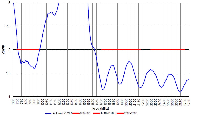
Operating frequency range |
698 to 960 MHz1710 to 2170 MHz2300 to 2700 MHz |
|
VSWR |
2:1 max |
|
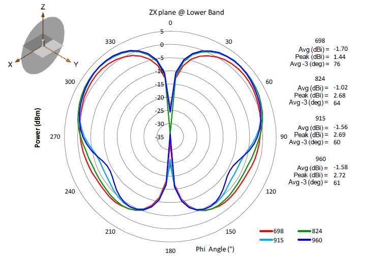
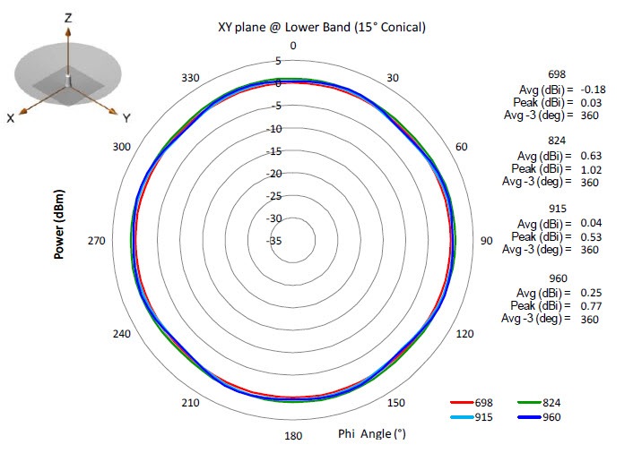
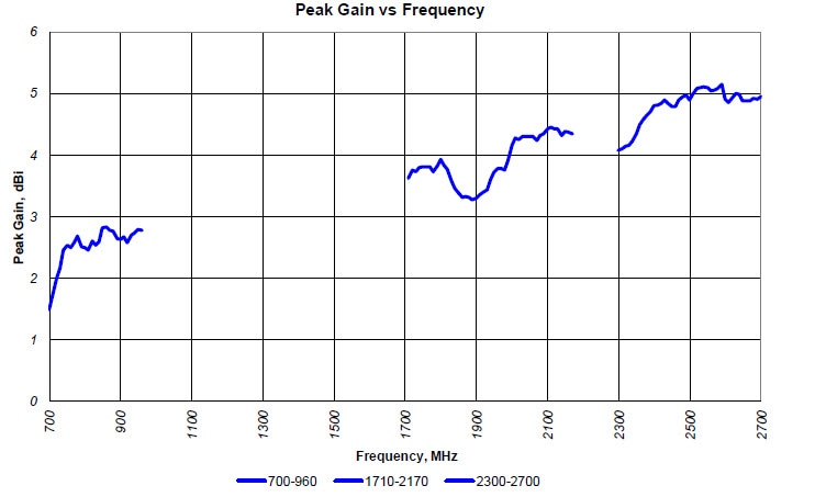
Peak gain 698 to 960 MHz |
2.8 dBi |
|
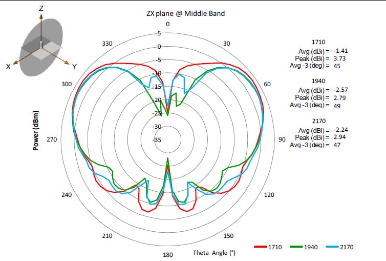
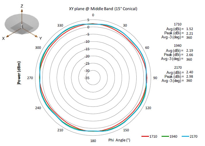
Peak gain 1710 to 2170 MHz |
4.3 dBi |
|
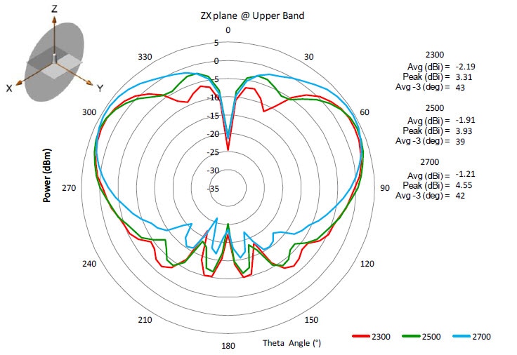
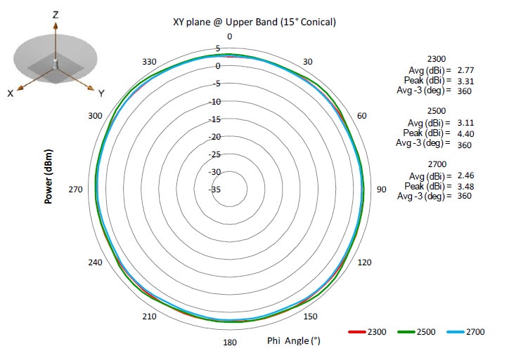
Peak gain 2300 to 2700 MHz |
5.0 dBi |
|
Average gain @15 degrees elevation 698 to 960 MHz |
0.9 dBi +/- 1.0 dB |
|
Average gain @15 degrees elevation 1710 to 2170 MHz |
3.0 dBi +/- 1.0 dB |
|
Average gain @15 degrees elevation 2300 to 2700 MHz |
4.0 dBi +/- 1.0 dB |
|
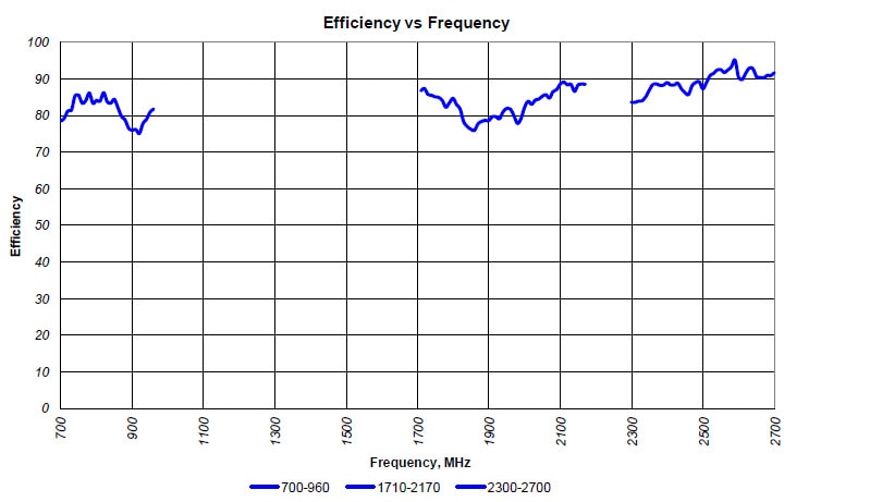
Efficiency 698 to 960/1710 to 2170/2300 to 2700 MHz: |
minimum 75% |
|
Polarization |
Vertical |
|
HPBW Horizontal plane @15 degrees |
Omni, 360 degree |
|
HPBW Vertical plane 698 to 960 MHz |
66 degrees average |
|
HPBW Vertical plane 1710 to 2170 MHz |
47 degrees average |
|
HPBW Vertical plane 2300 to 2700 MHz |
42 degrees average |
|
Power handling, CW |
10 W |
|
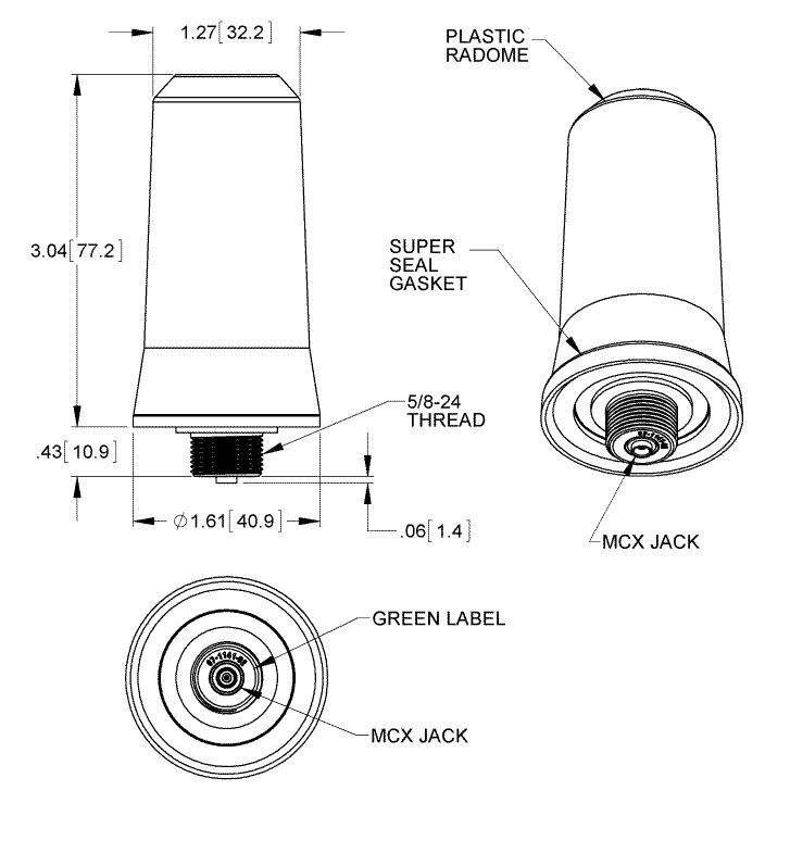
Connector type |
MCX jack |
The following is a summary of the monopole antenna specifications:
|
Specification |
Description |
|---|---|
|
Plastic radome |
PC/polyester blend, .110 thick min. |
|
Flammability |
UL94 V-0 |
|
Color |
Cisco gray |
|
Ingress protection |
IP67 |
|
Weight |
90 g |
|
Wind-loading |
165 MPH |
|
Overall length |
3.04 inches |
|
Installation torque |
6 to 9 ft/lbs |
|
Installation tool |
Recommended strap wrench, similar to McMaster Car P/N: 5448A31 |
|
Operating temperature |
-40 to 185 degrees F (-40 to 85 degrees C) |
All radiation patterns, gain, and VSWR were measured with the antenna mounted at the center of a 12-by-12-inch ground plane.
Antennas are only sold as antenna + cable kits. The kit will contain one or more antennas, gaskets, and coaxial cables. See the following:
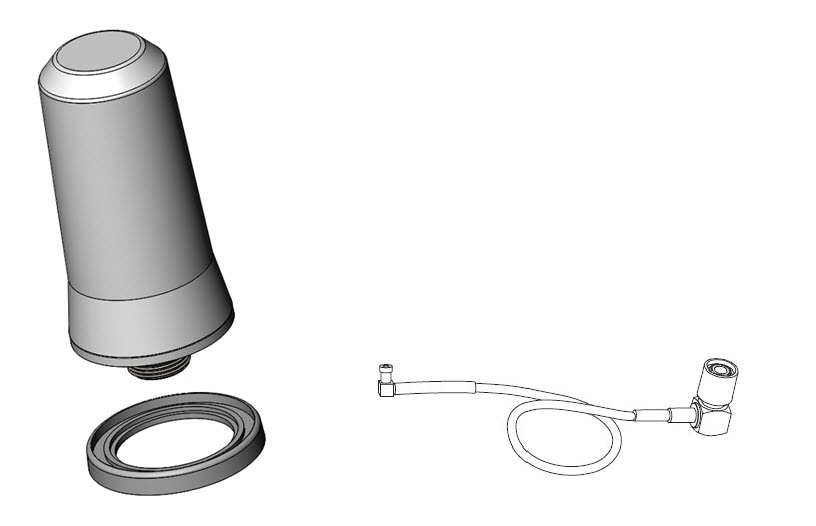
The antenna and other items contained in all of the kits are identical. Quantity changes depending on the kit selected.
|
Antenna quantity |
Gasket quantity |
10.5” RF Cable quantity |
Tie Wrap quantity |
|
|---|---|---|---|---|
|
ANT-MP2-I-OUT-M |
1 |
1 |
1 |
1 |
|
ANT-MP2-I-O-SS-M |
2 |
2 |
2 |
2 |
 Warning |
This warning symbol means danger. You are in a situation that could cause bodily injury. Before you work on any equipment, be aware of the hazards involved with electrical circuitry and be familiar with standard practices for preventing accidents. Use the statement number provided at the end of each warning to locate its translation in the translated safety warnings that accompanied this device. Statement 1071 |
Warning |
Do not work on the system or connect or disconnect cables during periods of lightning activity. Statement 1001 |
Warning |
Do not locate the outdoor antenna near overhead power lines or other electric light or power circuits, or where it can come into contact with such circuits. When installing the antenna, take extreme care not to come into contact with such circuits, as they may cause serious injury or death. For proper installation and grounding of the antenna, please refer to national and local codes (for example, U.S.:NFPA 70, National Electrical Code, Article 810, Canada:Canadian Electrical Code, Section 54). Statement 1052 |
Warning |
In order to comply with FCC radio frequency (RF) exposure limits, antennas should be located at a minimum of 7.9 inches (20 cm) or more from the body of all persons. Statement 332 |
Each year hundreds of people are killed or injured when attempting to install an antenna. In many of these cases, the victim was aware of the danger of electrocution, but did not take adequate steps to avoid the hazard.
Warning |
For your safety, and to help you achieve a good installation, please read and follow these safety precautions. They may save your life! |
For your safety, read and follow these safety precautions.
This section covers the following topics:
This Cisco Multi-purpose Integrated Antenna is designed to be mounted directly onto the router.
In addition to antenna orientation, wireless access point installation location with respect to all wireless clients plays a significant role in determining overall network performance.
Because antennas transmit and receive radio signals, their performance can be adversely affected by the surrounding environment including distance between the Field Area Router (FAR) and cellular base station, physical obstructions, or radio frequency (RF) interference.
In addition to the parts included in the antenna kit described in the previous section, you must provide the following tool to install the antenna on the router:
Follow these steps to install the antenna onto the router:
| Step 1 |
Remove the plug on the antenna connector if one is present. |
||||||||||
| Step 2 |
Attach the monopole antenna to your desired antenna port. Do not tighten the antenna completely—stop tightening so that the antenna is not fully installed. 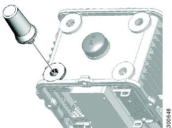
|
||||||||||
| Step 3 |
From the chassis interior, the antenna MCX jack should be visible in the plug. With one hand, position the right-angle end of the antenna cable to the antenna’s MCX jack. With your other hand, push the cable end so it inserts into the MCX jack of the antenna. 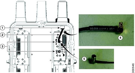
|
||||||||||
| Step 4 |
From the exterior of the router, tighten the antenna using the torque wrench. Tighten to 6 to 7 ft-lbs. |
||||||||||
| Step 5 |
From the interior of the router, install the coaxial end of the cable to the appropriate connector on your installed module. The antenna and module ports should be the same color (red, yellow, or green).
|
Modifications to this product not authorized by Cisco could void the FCC approval and negate your authority to operate the product.
The Cisco implementation of TCP header compression is an adaptation of a program developed by the University of California, Berkeley (UCB) as part of UCB’s public domain version of the UNIX operating system. All rights reserved. Copyright © 1981, Regents of the University of California.
NOTWITHSTANDING ANY OTHER WARRANTY HEREIN, ALL DOCUMENT FILES AND SOFTWARE OF THESE SUPPLIERS ARE PROVIDED “AS IS” WITH ALL FAULTS. CISCO AND THE ABOVE-NAMED SUPPLIERS DISCLAIM ALL WARRANTIES, EXPRESSED OR IMPLIED, INCLUDING, WITHOUT LIMITATION, THOSE OF MERCHANTABILITY, FITNESS FOR A PARTICULAR PURPOSE AND NONINFRINGEMENT OR ARISING FROM A COURSE OF DEALING, USAGE, OR TRADE PRACTICE.
IN NO EVENT SHALL CISCO OR ITS SUPPLIERS BE LIABLE FOR ANY INDIRECT, SPECIAL, CONSEQUENTIAL, OR INCIDENTAL DAMAGES, INCLUDING, WITHOUT LIMITATION, LOST PROFITS OR LOSS OR DAMAGE TO DATA ARISING OUT OF THE USE OR INABILITY TO USE THIS MANUAL, EVEN IF CISCO OR ITS SUPPLIERS HAVE BEEN ADVISED OF THE POSSIBILITY OF SUCH DAMAGES.
Any Internet Protocol (IP) addresses and phone numbers used in this document are not intended to be actual addresses and phone numbers. Any examples, command display output, network topology diagrams, and other figures included in the document are shown for illustrative purposes only. Any use of actual IP addresses or phone numbers in illustrative content is unintentional and coincidental.
All printed copies and duplicate soft copies of this document are considered uncontrolled. See the current online version for the latest version.
Cisco has more than 200 offices worldwide. Addresses, phone numbers, and fax numbers are listed on the Cisco website at www.cisco.com/go/offices .
© 2015-2021 Cisco Systems, Inc. All rights reserved.
 Feedback