Segment Routing Overview
Segment routing is a method of forwarding packets on the network based on the source routing paradigm. The forward path is determined before the packet is even sent. The path is encoded in the packet, at the source as a list of segments bearing forwarding instructions. At each hop the top segment, which references the router information base (RIB), is used to identify the next hop. Segments are stacked in order, at the top of the packet header. When the top segment contains the identity of another node, the receiving node uses ECMP to move the packet to the next hop. When the identity is that of the receiving node, the node pops the top segment and performs the task required by the next segment.
Segment routing leverages other interior gateway protocols such as IS-IS, OSPF, and MPLS for efficient and flexible forwarding. Segment routing is a faster and more efficient way of forwarding traffic in the MPLS core network.
To understand the working of segment routing, let’s understand how MPLS traffic engineering works.
How Does Segment Routing Work?
A router in a Segment Routing network is capable of selecting any path to forward traffic, whether it is explicit or Interior Gateway Protocol (IGP) shortest path. Segments represent subpaths that a router can combine to form a complete route to a network destination. Each segment has an identifier (Segment Identifier) that is distributed throughout the network using new IGP extensions. The extensions are equally applicable to IPv4 and IPv6 control planes. Unlike the case for traditional MPLS networks, routers in a Segment Router network do not require Label Distribution Protocol (LDP) and Resource Reservation Protocol - Traffic Engineering (RSVP-TE) to allocate or signal their segment identifiers and program their forwarding information.
Each router (node) and each link (adjacency) has an associated segment identifier (SID). Node segment identifiers are globally unique and represent the shortest path to a router as determined by the IGP. The network administrator allocates a node ID to each router from a reserved block. On the other hand, an adjacency segment identifiers are locally significant and represent a specific adjacency, such as egress interface, to a neighboring router. Routers automatically generate adjacency identifiers outside of the reserved block of node IDs. In an MPLS network, a segment identifier is encoded as an MPLS label stack entry. Segment IDs direct the data along a specified path. There are two kinds of segment IDS:
- Prefix SID—A segment ID that contains an IP address prefix calculated by an IGP in the service provider core network. Prefix SIDs are globally unique. A node SID is a special form of prefix SID that contains the loop-back address of the node as the prefix. It is advertised as an index into the node specific SR Global Block or SRGB.
- Adjacency SID—A segment ID that contains an advertising router’s adjacency to a neighbor. An adjacency SID is a link between two routers. Since the adjacency SID is relative to a specific router, it is locally unique.
Examples for Segment Routing
The following figure illustrates an MPLS network with five routers using Segment Routing, IS-IS, a label range of 100 to 199 for node IDs, and 200 and higher for adjacency IDs. IS-IS would distribute IP prefix reachability alongside segment ID (the MPLS label) across the network.
Figure 1-1 An MPLS Network with Five Routers Using Segment Routing
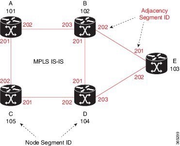
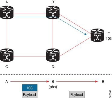
In the previous example, any router sending traffic to router E would push label 103 (router E node segment identifier) to forward traffic using the IS-IS shortest path. The MPLS label-swapping operation at each hop preserves label 103 until the packet arrives at E (Figure 2). On the other hand, adjacency segments behave differently. For example, if a packet arrives at Router D with a top-of-stack MPLS label of 203 (D-to-E adjacency segment identifier), Router D would pop the label and forward the traffic to Router E.
Figure 1-2 MPLS Label-Swapping Operation
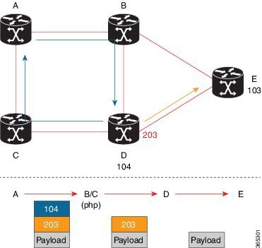
Segment identifiers can be combined as an ordered list to perform traffic engineering. A segment list can contain several adjacency segments, several node segments, or a combination of both depending on the forwarding requirements. In the previous example, Router A could alternatively push label stack (104, 203) to reach Router E using the shortest path and all applicable ECMPs to Router D and then through an explicit interface onto the destination (Figure 3). Router A does not need to signal the new path, and the state information remains constant in the network. Router A ultimately enforces a forwarding policy that determines which flows destined to router E are switched through a particular path.
Figure 1-3 Destination Path of Router E
Benefits of Segment Routing
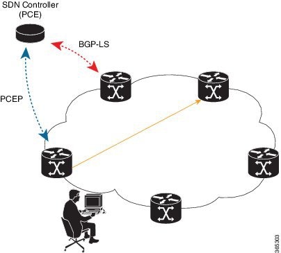
- Ready for SDN—Segment Routing is a compelling architecture conceived to embrace Software-Defined Network (SDN) and is the foundation for Application Engineered Routing (AER). It strikes a balance between network-based distributed intelligence, such as automatic link and node protection, and controller-based centralized intelligence, such as traffic optimization. It can provide strict network performance guarantees, efficient use of network resources, and very high scalability for application-based transactions. The network uses minimal state information to meet these requirements. Segment routing can be easily integrated with a controller-based SDN architecture. Below figure illustrates a sample SDN scenario where the controller performs centralized optimization, including bandwidth admission control. In this scenario, the controller has a complete picture of the network topology and flows. A router can request a path to a destination with certain characteristics, for example, delay, bandwidth, diversity. The controller computes an optimal path and returns the corresponding segment list, such as an MPLS label stack, to the requesting router. At that point, the router can inject traffic with the segment list without any additional signaling in the network.
- In addition, segment lists allow complete network virtualization without adding any application state to the network. The state is encoded in the packet as a list of segments. Because the network only maintains segment state, it can support a large number - and a higher frequency - of transaction-based application requests without creating any burden on the network.
- Simplified—
–![]() When applied to the MPLS data plane, Segment Routing offers the ability to tunnel MPLS services (VPN, VPLS, and VPWS) from an ingress provider edge to an egress provider edge without any other protocol than an IGP (ISIS or OSPF).
When applied to the MPLS data plane, Segment Routing offers the ability to tunnel MPLS services (VPN, VPLS, and VPWS) from an ingress provider edge to an egress provider edge without any other protocol than an IGP (ISIS or OSPF).
–![]() Simpler operation without separate protocols for label distribution (for example, no LDP or RSVP).
Simpler operation without separate protocols for label distribution (for example, no LDP or RSVP).
–![]() No complex LDP or IGP synchronization to troubleshoot.
No complex LDP or IGP synchronization to troubleshoot.
–![]() Better utilization of installed infrastructure, for lower capital expenditures (CapEx), with ECMP-aware shortest path forwarding (using node segment IDs).
Better utilization of installed infrastructure, for lower capital expenditures (CapEx), with ECMP-aware shortest path forwarding (using node segment IDs).
- Supports Fast Reroute (FRR)— Deliver automated FRR for any topology. In case of link or node failures in a network, MPLS uses the FRR mechanism for convergence. With segment routing, the convergence time is sub-50-msec.
- Large-scale Data Center-
–![]() Segment Routing simplifies MPLS-enabled data center designs using Border Gateway Protocol (BGP) RFC 3107 - IPv4 labeled unicast among Top-of-the-Rack/Leaf/Spine switches.
Segment Routing simplifies MPLS-enabled data center designs using Border Gateway Protocol (BGP) RFC 3107 - IPv4 labeled unicast among Top-of-the-Rack/Leaf/Spine switches.
–![]() BGP distributes the node segment ID, equivalent to IGP node SID.
BGP distributes the node segment ID, equivalent to IGP node SID.
–![]() Any node within the topology allocates the same BGP segment for the same switch.
Any node within the topology allocates the same BGP segment for the same switch.
–![]() The same benefits are provided as for IGP node SID: ECMP and automated FRR (BGP PIC (Prefix Independent Convergence).
The same benefits are provided as for IGP node SID: ECMP and automated FRR (BGP PIC (Prefix Independent Convergence).
–![]() This is a building block for traffic engineering - SR TE data center fabric optimization.
This is a building block for traffic engineering - SR TE data center fabric optimization.
–![]() Avoid thousands of labels in LDP database.
Avoid thousands of labels in LDP database.
–![]() Avoid thousands of MPLS Traffic Engineering LSPs in the network.
Avoid thousands of MPLS Traffic Engineering LSPs in the network.
–![]() Avoid thousands of tunnels to configure.
Avoid thousands of tunnels to configure.
–![]() Segment Routing provides a simple solution for disjointness enforcement within a so-called “dual-plane” network, where the route to an edge destination from a given plane stays within the plane unless the plane is partitioned.
Segment Routing provides a simple solution for disjointness enforcement within a so-called “dual-plane” network, where the route to an edge destination from a given plane stays within the plane unless the plane is partitioned.
–![]() An additional SID “anycast” segment ID allows the expression of macro policies such as: "Flow 1 injected in node A toward node Z must go via plane 1" and "Flow 2 injected in node A towards node Z must go via plane 2."
An additional SID “anycast” segment ID allows the expression of macro policies such as: "Flow 1 injected in node A toward node Z must go via plane 1" and "Flow 2 injected in node A towards node Z must go via plane 2."
–![]() Controllers and orchestration platforms can interact with Segment Routing traffic engineering for centralized optimization, such as WAN optimization.
Controllers and orchestration platforms can interact with Segment Routing traffic engineering for centralized optimization, such as WAN optimization.
–![]() Network changes such as congestion can trigger an application to optimize (recompute) the placement of segment routing traffic engineering tunnels.
Network changes such as congestion can trigger an application to optimize (recompute) the placement of segment routing traffic engineering tunnels.
–![]() Segment Routing tunnels are dynamically programmed onto the network from an orchestrator using southbound protocols like PCE.
Segment Routing tunnels are dynamically programmed onto the network from an orchestrator using southbound protocols like PCE.
–![]() Agile network programming is possible since Segment Routing tunnels do not require signaling and per-flow state at midpoints and tail end routers.
Agile network programming is possible since Segment Routing tunnels do not require signaling and per-flow state at midpoints and tail end routers.
–![]() Segment Routing allows centralized EPE.
Segment Routing allows centralized EPE.
–![]() A controller instructs an ingress provider edge and content source to use a specific egress provider edge and specific external interface to reach a destination.
A controller instructs an ingress provider edge and content source to use a specific egress provider edge and specific external interface to reach a destination.
–![]() BGP “peering” segment IDs are used to express source-routed inter-domain paths.
BGP “peering” segment IDs are used to express source-routed inter-domain paths.
–![]() Controllers learn BGP peering SIDs and the external topology of the egress border router through BGP Link Status (BGP-LS) EPE routes.
Controllers learn BGP peering SIDs and the external topology of the egress border router through BGP Link Status (BGP-LS) EPE routes.
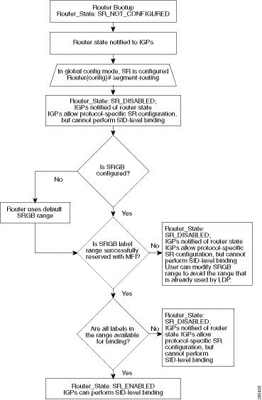
Segment Routing Limitations
Figure 1-5 Segment Routing State Flow
- Segment Routing must be globally enabled on the chassis before enabling it on the IGPs, like ISIS or OSPF.
- Segment routing must be configured on the ISIS instance before configuring a prefix SID value.
- The prefix SID value must be removed from all the interfaces under the same ISIS instance before disabling segment routing.
General Limitations of Segment Routing
Configuring Segment Routing
1.![]() Globally enable segment routing:
Globally enable segment routing:
2.![]() Specify the range of MPLS labels to be used to instantiate the segment routing SIDs into MPLS data plane.
Specify the range of MPLS labels to be used to instantiate the segment routing SIDs into MPLS data plane.
3.![]() Associate SID values with local prefix values.
Associate SID values with local prefix values.
Configuring Segment Routing on an IGP Instance
This command enables MPLS on all interfaces and programs the MPLS labels for forwarding.

Note![]() If the area keyword is specified, segment routing is enabled only on that area.
If the area keyword is specified, segment routing is enabled only on that area.
Note![]() The disable keyword cab be used only if the area keyword is specified.
The disable keyword cab be used only if the area keyword is specified.
Enabling Advertisement of Mapping Server Prefix Ranges
Global segment routing configuration may contain prefix-to-SID mapping entries for prefixes that are not local to the router. Each of these entries specifies a range of prefixes. Remote mapping entries can be used to find SIDs for prefixes connected to routers that do not support SR and hence not capable of advertising SIDs themselves. This capability is part of SR-LDP inter-working functionality. OSPF learns the ranges configured in the global SR configuration and advertises them in the Extended Prefix Range TLVs.
To permit an OSPF instance to advertise mapping entries configured in the global SR mode, use the following command in router mode.
Note![]() By default, this command is disabled. That is, no mapping ranges are advertised by OSPF even if they are configures in the global SR mode.
By default, this command is disabled. That is, no mapping ranges are advertised by OSPF even if they are configures in the global SR mode.
Disabling the Mapping Server
When computing SIDs for prefixes, IGPs consider the prefix ranges received from mapping servers in the network by default.However, if this functionality needs to be disabled, use the following command in router mode. If the SR-LDP feature needs to be disabled, it is done in router-mode:
Note![]() This command does not affect processing of 'native' SIDs, that is, those SIDs that are advertised in the Extended Prefix TLVs by routers to whom the prefix is locally connected.
This command does not affect processing of 'native' SIDs, that is, those SIDs that are advertised in the Extended Prefix TLVs by routers to whom the prefix is locally connected.
 Feedback