Installing and Configuring Cisco SM-X Single-Wide High Density Analog Voice Service Module on Cisco 4000 Series ISR
Available Languages
Table of Contents
Information About Single-Wide High Density Analog Voice Service Modules
Cisco SM-X-8-FXS/12FXO Service Module Specifications
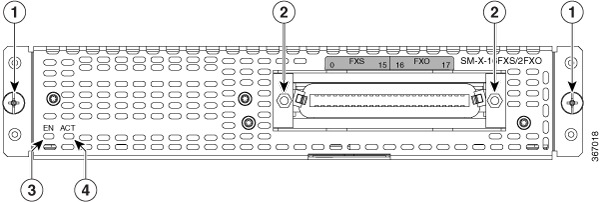
Cisco SM-X-16-FXS/2FXO Service Module Specifications
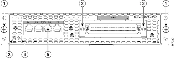
Cisco SM-X-24-FXS/4FXO Service Module Specifications
Technical and Compliance Specifications
Platform and Software Requirements
Installing Cisco SM-X Single-Wide Service Module On Cisco 4000 Series Integrated Services Routers
Removing Cisco SM-X single-wide Service Module On Cisco 4000 Series Integrated Services Routers
Connecting Cisco SM-X Single-wide Service Module to a Network
Configuring Single-wide High Density Analog Voice Service Module
Installing and Configuring Cisco SM-X Single-Wide High Density Analog Voice Service Module on Cisco 4000 Series ISR
This document provides information that you should know before and during the installation of the new Cisco SM-X Single Wide High Density Analog Voice Service Module on Cisco 4000 Series Integrated Services Routers.
Contents
This guide contains the following sections:
■![]() Information About Single-Wide High Density Analog Voice Service Modules
Information About Single-Wide High Density Analog Voice Service Modules
■![]() Installing Cisco SM-X Single-Wide Service Module On Cisco 4000 Series Integrated Services Routers
Installing Cisco SM-X Single-Wide Service Module On Cisco 4000 Series Integrated Services Routers
■![]() Configuring Single-wide High Density Analog Voice Service Module
Configuring Single-wide High Density Analog Voice Service Module
Information About Single-Wide High Density Analog Voice Service Modules
Cisco High-Density Analog Voice and Fax Service Modules provide enterprises, managed services providers, and service providers the ability to directly connect public-switched telephone networks (PSTNs) and existing telephony equipment to Cisco 4000 Series Integrated Services Routers. These fixed-port (FXS and FXO) modules provide Dual-Tone Multifrequency (DTMF) detection, voice compression and decompression, call progress tone generation, Voice Activity Detection (VAD), echo cancellation, and adaptive jitter buffering.
Cisco SM-X is a service module that can be inserted into the service module slots on Cisco 4000 Series Integrated Services Routers. Cisco SM-X provides VoIP connectivity to analog devices such as analog desk phones, analog conference room phones, fax machines and modems. Cisco SM-X provides a high number of FXS ports per RU on Cisco 4000 Series Integrated Services Routers.
The FXO port is used to connect to PBX or key systems, or to provide off-premises connections to the PSTN. It supports battery reversal detection and caller ID. The FXO port is also used to connect to analog Centralized Automatic Message Accounting (CAMA) trunks to provide dedicated E-911 service (in North America only).
The FXS port is used to connect analog phones, modems, fax machines, and speaker phones to an enterprise IP voice system, so you can use them as extensions to your Cisco or third-party IP call-control system. Having these devices tightly integrated with the IP-based phone system is advantageous for increased manageability, scalability, and cost-effectiveness. The Direct Inward Dialing (DID) port is used to provide off-premises DID connection from the central office. It serves only incoming calls from the PSTN. Caller ID is not supported in DID mode.
Cisco High-Density Analog Voice and Fax Service Modules are available in a single-wide or double-wide form factor.
Cisco SM-X single-wide service module has the following ports:
■![]() 8 Port FXS and 12 Port FXO—Includes 8 FXS ports and 12 FXPO ports
8 Port FXS and 12 Port FXO—Includes 8 FXS ports and 12 FXPO ports
■![]() 16 Port FXS and 2 Port FXO—Includes 16 FXS ports and 2 FXPO ports
16 Port FXS and 2 Port FXO—Includes 16 FXS ports and 2 FXPO ports
■![]() 24 Port FXS and 4 Port FXO—Includes 24 FXS ports and 4 FXPO ports
24 Port FXS and 4 Port FXO—Includes 24 FXS ports and 4 FXPO ports
The following table provides information about Cisco SM-X single-wide service module SKU:
The slot, bay, and port information for Cisco SM-X single-wide FXS service module is as follows:
The slot, bay, and port information for Cisco SM-X single-wide FXO service module is as follows:
Features and Benefits
The new generation of Cisco High-Density Analog Voice and Fax Service Modules improves upon the previous high-density analog and digital extension modules (EVMs). These improvements are as follows:
■![]() On-board Digital Signal Processor (DSP)— The FXO and FXS service modules contain an onboard DSP and don’t require the router to have a dedicated packet voice DSP module (PVDM) on the motherboard. The DSP on the voice module is necessary for the voice features. It also provides for echo cancellation of up to 128-ms echo-tail length for demanding network conditions.
On-board Digital Signal Processor (DSP)— The FXO and FXS service modules contain an onboard DSP and don’t require the router to have a dedicated packet voice DSP module (PVDM) on the motherboard. The DSP on the voice module is necessary for the voice features. It also provides for echo cancellation of up to 128-ms echo-tail length for demanding network conditions.
■![]() Support for Online Insertion and Removal (OIR)— The FXS and FXO service modules support Online Insertion and Removal (OIR), reducing the downtime required for new or replacement modules. The service modules can be inserted into the SM-X slot on the supported Cisco 4000 Series ISRs without powering off the router.
Support for Online Insertion and Removal (OIR)— The FXS and FXO service modules support Online Insertion and Removal (OIR), reducing the downtime required for new or replacement modules. The service modules can be inserted into the SM-X slot on the supported Cisco 4000 Series ISRs without powering off the router.
■![]() FXS-E (extended loops) support— FXS ports on the new modules support FXS-E with the following details:
FXS-E (extended loops) support— FXS ports on the new modules support FXS-E with the following details:
–![]() Higher loop current (35 mA) to accommodate specialty phones
Higher loop current (35 mA) to accommodate specialty phones
–![]() Longer loop length for loops with 26 AWG wire, up to 11,000 feet (3400 meters)
Longer loop length for loops with 26 AWG wire, up to 11,000 feet (3400 meters)
–![]() Higher ringing voltage (65 Vrms, no load)
Higher ringing voltage (65 Vrms, no load)
Note: Switching between the modes requires reload of the ISR chassis.
FXO failover bypass ports— A failover bypass port, also called a failover trunk bypass, provides a way to use designated analog phone ports to make phone calls through the PSTN during a power outage.
In addition to the above features, the service modules supports the following features:
■![]() G722, iLBC, GSMAMR-NB, and Internet Speech Audio Codec (iSAC)
G722, iLBC, GSMAMR-NB, and Internet Speech Audio Codec (iSAC)
■![]() Fax detection, pass-through, and relay (T.38)
Fax detection, pass-through, and relay (T.38)
■![]() Real-Time Control Protocol (RTCP)
Real-Time Control Protocol (RTCP)
■![]() Real-Time Transport Protocol (RTP)
Real-Time Transport Protocol (RTP)
■![]() Noise reduction is on the roadmap
Noise reduction is on the roadmap
■![]() Support for either FXS or DID functionality
Support for either FXS or DID functionality
■![]() Message-Waiting Indicator (MWI)
Message-Waiting Indicator (MWI)
■![]() Cable detection: GR909 line test
Cable detection: GR909 line test
■![]() Support for both ground-start and loop-start modes
Support for both ground-start and loop-start modes
■![]() Call Detail Record (CDR) information
Call Detail Record (CDR) information
■![]() Support for interworking with Cisco Unified Communications Manager (Skinny Client Control Protocol [SCCP]), H.323, Session Initiation Protocol (SIP), and Media Gateway Control Protocol (MGCP) 1.0
Support for interworking with Cisco Unified Communications Manager (Skinny Client Control Protocol [SCCP]), H.323, Session Initiation Protocol (SIP), and Media Gateway Control Protocol (MGCP) 1.0
Analog Phone Connectivity
Cisco High-Density Analog Voice and Fax Service Modules are ideal for analog phone deployments ranging from centralized to sparsely concentrated or distributed topologies. Cisco 4000 Series Integrated Services Routers offer many supplementary analog calling features, depending on the call control and signaling type used. All supplementary analog features are supported through the FXS and FXO service modules. The analog interface on Cisco 4000 Series also supports Feature Access Codes (FACs) for invoking supplementary services.
Fax and Modem Connectivity
FXS ports on the Cisco High-Density Analog Voice and Fax Service Modules support fax machines and modems. When using fax machines, the gateways support T.38 fax relay and fax pass-through. T.38 fax relay technologies allow transfer of faxes across the network with high reliability using less bandwidth than a voice call. All modems can be connected to the Cisco VG Series Gateways and are transferred over the network using modem pass-through.
Protocols Supported
The voice gateways support the following protocols:
■![]() Real-Time Transport Protocol (RTP)
Real-Time Transport Protocol (RTP)
■![]() Secure Real-Time Transport Protocol (SRTP)
Secure Real-Time Transport Protocol (SRTP)
■![]() Trivial File Transfer Protocol (TFTP)
Trivial File Transfer Protocol (TFTP)
■![]() Simple Network Management Protocol (SNMP)
Simple Network Management Protocol (SNMP)
■![]() Dynamic Host Configuration Protocol (DHCP)
Dynamic Host Configuration Protocol (DHCP)
■![]() Cisco Unified Communications Manager or Cisco Unified Communications Manager Express redundancy support using Hot Standby Router Protocol (HSRP)
Cisco Unified Communications Manager or Cisco Unified Communications Manager Express redundancy support using Hot Standby Router Protocol (HSRP)
■![]() Call survivability: MGCP failover to an H.323 connection to the Survivable Remote Site Telephony (SRST) router
Call survivability: MGCP failover to an H.323 connection to the Survivable Remote Site Telephony (SRST) router
■![]() T.38 fax relay and modem pass-through
T.38 fax relay and modem pass-through
■![]() Codec support: G.711, and G.729a
Codec support: G.711, and G.729a
■![]() RADIUS and TACACS+ for Telnet and authorization
RADIUS and TACACS+ for Telnet and authorization
The following table lists the feature specifications for Cisco SM-X single-wide service module.

Technical and Compliance Specifications
The following table details the technical specifications of Cisco SM-X single-wide service modules.
The following table details the compliance specifications of Cisco SM-X single-wide service modules.
Platform and Software Requirements
Cisco High-Density Analog Voice and Fax Service Modules are supported on Cisco 4000 Series Integrated Services Routers effective with Cisco IOS XE Fuji 16.7.1 or later. The service modules provide gateway services for Cisco Unified Communications using Cisco Unified Communications Manager with SRST or Cisco Unified Communications Manager Express. The following table provides information about the software version that is compatible with FXO and FXS service modules.
Table 7 Compatible Software Versions with the FXO and FXS Service Modules
Configuration Methods
After Cisco SM-X single-wide service module is operating and able to communicate, use the procedures in Cisco SM-X single-wide service module Software Configuration Guide to configure the specific services and functions or to make changes to the existing configuration.
There are multiple methods for configuring Cisco 4000 Series Integrated Services Routers:
■![]() Configuration mode—Cisco IOS software CLI
Configuration mode—Cisco IOS software CLI
■![]() setup command facility—Remote configuration through a LAN
setup command facility—Remote configuration through a LAN
■![]() SNMP-based application—CiscoView or HP OpenView
SNMP-based application—CiscoView or HP OpenView
■![]() HTTP-based configuration server—Provides access to the CLI from a web browser
HTTP-based configuration server—Provides access to the CLI from a web browser
Safety Precautions
This section contains the following warning statements. A warning means danger. You are in a situation that could cause bodily injury. Before working on an equipment, be aware of the hazards involved with electrical circuitry and standard safety practices to prevent accidents.
This warning symbol means danger. You are in a situation that could cause bodily injury. Before you work on any equipment, be aware of the hazards involved with electrical circuitry and be familiar with standard practices for preventing accidents. Use the statement number provided at the end of each warning to locate its translation in the translated safety warnings that accompanied this device.
Warning: Do not work on the system or connect or disconnect cables during periods of lightning activity. Statement 1001
Warning: To avoid electric shock, do not connect safety extra-low voltage (SELV) circuits to telephone-network voltage (TNV) circuits. LAN ports contain SELV circuits, and WAN ports contain TNV circuits. Some LAN and WAN ports both use RJ-45 connectors. Use caution when connecting cables. Statement 1021
Warning: Hazardous network voltages are present in WAN ports regardless of whether power to the unit is OFF or ON. To avoid electric shock, use caution when working near WAN ports. When detaching cables, detach the end away from the unit first. Statement 1026
Warning: This equipment contains a ring signal generator (ringer), which is a source of hazardous voltage. Do not touch the RJ-11 (phone) port wires (conductors), the conductors of a cable connected to the RJ-11 port, or the associated circuit-board when the ringer is active. The ringer is activated by an incoming call. Statement 1042
Warning: For connections outside the building where the equipment is installed, the following ports must be connected through an approved network termination unit with integral circuit protection.
FXS Statement 1044
Installing Cisco SM-X Single-Wide Service Module On Cisco 4000 Series Integrated Services Routers
1.![]() Shut down the electrical power to the slot in the router either by turning off the electrical power to the router or by issuing the online insertion and removal (OIR) commands. Leave the power cable plugged in to channel ESD voltages to ground. For more information on OIR, see the “Managing Cisco Enhanced Services and Network Interface Modules” chapter in the Cisco 4000 Series ISRs Software Configuration Guide.
Shut down the electrical power to the slot in the router either by turning off the electrical power to the router or by issuing the online insertion and removal (OIR) commands. Leave the power cable plugged in to channel ESD voltages to ground. For more information on OIR, see the “Managing Cisco Enhanced Services and Network Interface Modules” chapter in the Cisco 4000 Series ISRs Software Configuration Guide.
2.![]() Remove the blank faceplates installed over the network interface module slot that you intend to use.
Remove the blank faceplates installed over the network interface module slot that you intend to use.
Tip: Save blank faceplates for future use.
3.![]() Align the module with the guides in the chassis walls or slot divider and slide it gently into the NIM slot on the router.
Align the module with the guides in the chassis walls or slot divider and slide it gently into the NIM slot on the router.
4.![]() Push the module into place until you feel the edge connector seat securely into the connector on the router backplane. The module faceplate should contact the chassis rear panel.
Push the module into place until you feel the edge connector seat securely into the connector on the router backplane. The module faceplate should contact the chassis rear panel.
5.![]() Using a number 1 Phillips or flat-blade screwdriver, tighten the captive screws on the service module.
Using a number 1 Phillips or flat-blade screwdriver, tighten the captive screws on the service module.
6.![]() Connect the module to the network and reenable the power to the slot in the router.
Connect the module to the network and reenable the power to the slot in the router.
Removing Cisco SM-X single-wide Service Module On Cisco 4000 Series Integrated Services Routers
1.![]() Shut down the electrical power to the slot in the router either by turning off the electrical power to the router or by issuing the online insertion and removal (OIR) commands. Leave the power cable plugged in to channel ESD voltages to ground. For more information on OIR, see the “Managing Cisco Enhanced Services and Network Interface Modules” chapter in the Cisco 4000 Series ISRs Software Configuration Guide.
Shut down the electrical power to the slot in the router either by turning off the electrical power to the router or by issuing the online insertion and removal (OIR) commands. Leave the power cable plugged in to channel ESD voltages to ground. For more information on OIR, see the “Managing Cisco Enhanced Services and Network Interface Modules” chapter in the Cisco 4000 Series ISRs Software Configuration Guide.
2.![]() Using a number 1 Phillips or flat-blade screwdriver, loosen the captive screws on the NIM.
Using a number 1 Phillips or flat-blade screwdriver, loosen the captive screws on the NIM.
3.![]() Slide the service module out.
Slide the service module out.
4.![]() If you are not replacing the module, install a blank faceplate over the empty slot to ensure proper air flow.
If you are not replacing the module, install a blank faceplate over the empty slot to ensure proper air flow.
Connecting Cisco SM-X Single-wide Service Module to a Network
1.![]() Connect the serial cable to the connector on the Service module faceplate.
Connect the serial cable to the connector on the Service module faceplate.
2.![]() Use a RJ—21 cable to connect to SM-X single wide service module.
Use a RJ—21 cable to connect to SM-X single wide service module.
3.![]() Connect one end of the appropriate serial cable to the connector on the card faceplate.
Connect one end of the appropriate serial cable to the connector on the card faceplate.
4.![]() Turn on power to the router by pressing the power switch to the ON ( |) position.
Turn on power to the router by pressing the power switch to the ON ( |) position.
5.![]() Check that the CONN LED goes on, which indicates that the serial port detects the WAN serial connection.
Check that the CONN LED goes on, which indicates that the serial port detects the WAN serial connection.
Configuring Single-wide High Density Analog Voice Service Module
Prerequisites
■![]() Obtain two-wire line service from your service provider or from a PBX.
Obtain two-wire line service from your service provider or from a PBX.
■![]() Complete your company’s dial plan.
Complete your company’s dial plan.
■![]() Establish a working telephony network based on your company’s dial plan.
Establish a working telephony network based on your company’s dial plan.
■![]() Establish a working connection to the network.
Establish a working connection to the network.
■![]() Install appropriate voice interface hardware on the router
Install appropriate voice interface hardware on the router
■![]() Gather the following information about the telephony connection of the voice port:
Gather the following information about the telephony connection of the voice port:
–![]() Telephony signaling interface: FXO and FXS
Telephony signaling interface: FXO and FXS
–![]() Locale code (usually the country) for call progress tones
Locale code (usually the country) for call progress tones
–![]() For FXO, type of dialing: DTMF (touch-tone) or pulse and type of signal: loop-start or ground-start
For FXO, type of dialing: DTMF (touch-tone) or pulse and type of signal: loop-start or ground-start
■![]() Disconnect signaling by performing the following set of tasks:
Disconnect signaling by performing the following set of tasks:
–![]() supervisory disconnect signal
supervisory disconnect signal
–![]() no supervisory disconnect signal. See Understanding FXO Disconnect Problem for detailed configuration information.
no supervisory disconnect signal. See Understanding FXO Disconnect Problem for detailed configuration information.
■![]() If you are connecting a voice-port interface to a PBX, it is important to understand the PBX’s wiring scheme and timing parameters. You can gather this information from your PBX vendor or the reference manuals that accompany your PBX.
If you are connecting a voice-port interface to a PBX, it is important to understand the PBX’s wiring scheme and timing parameters. You can gather this information from your PBX vendor or the reference manuals that accompany your PBX.
Configuring an FXO Interface
Perform this task to configure the Single-wide High Density Analog Voice Service Module as an FXO interface.
Configuring an FXS Interface
Perform this task to configure the Single-wide High Density Analog Voice Service Module as an FXS interface.
Additional References
MIBS
Technical Assistance
Cisco and the Cisco logo are trademarks or registered trademarks of Cisco and/or its affiliates in the U.S. and other countries. To view a list of Cisco trademarks, go to this URL: www.cisco.com/go/trademarks. Third-party trademarks mentioned are the property of their respective owners. The use of the word partner does not imply a partnership relationship between Cisco and any other company. (1721R)
 Feedback
Contact Cisco
- Open a Support Case

- (Requires a Cisco Service Contract)