Additional Information
![]()
Troubleshooting Cisco SD-WAN Issues
This section describes problems, possible causes, recommended actions, and error messages, if applicable to the problem.
Troubleshooting Cisco SD-WAN Reachability Issues
|
Color |
Green |
Red |
Comment |
|---|---|---|---|
|
Deployment Status |
Provisioned |
Provisioned-Failed: See Troubleshooting notes. For more information, see Troubleshooting Cisco SD-WAN vEdge-Cloud Deployment Deployment Errors. |
Checks that VNF(s) is fully deployed and in active state. |
|
Reachability Status |
Reachable |
Not Reachable: See Troubleshooting notes. For more information, see Troubleshooting Cisco SD-WAN vEdge Reachability Errors. |
Checks the connectivity between the deployed vEdge and Cisco SD-WAN Control Plane. |
Troubleshooting Cisco SD-WAN vEdge-Cloud Deployment Errors
After the service packs are deployed on Cisco MSX, the customer configuration templates are imported into the Cisco Network Services Orchestrator (NSO) platform for automating network orchestration. These configurations are then pushed from Cisco MSX to customer devices as part of the orchestration of device configuration. If the SD-WAN provisioning is not successful, most times, it is due to wrong parameters in the deployment data on NSO. There are multiple NSO instances if you are deploying more than one service pack. Therefore, these steps must be performed on the service pack-specific NSO node. SD-WAN uses SD-Branch's NSO, so in this case, the nso node will be nso-vbranch.
Procedure
| Step 1 |
Log in to one of the kubernetes master nodes. |
| Step 2 |
Access the NSO node using this command: |
| Step 3 |
Change to vms user. |
| Step 4 |
Run NSO CLI |
| Step 5 |
Get the branch-cpe name, using the following command: Example: |
| Step 6 |
Check the deployment summary, using the following command. Replace the branch-cpe name with the name that was identified in step 2. For example: Example:The summary displays the problem, if any. In the above example, SYSTEM_IP variable is wrong, because of which ENCS was unable to configure the VNF and was unable to attach the deployed Control plane on Cisco MSX. |
Troubleshooting Cisco SD-WAN vEdge Reachability Errors
If there is no connectivity between the deployed vEdge and Cisco SD-WAN Control Plane:
Procedure
| Step 1 |
Login to the deployed vEdge and check the status of deployed vEdges.
|
| Step 2 |
Check the status of control connection, using the following command: If nothing shows up in the output, it shows that the vEdge is unable to establish dtls connection to vBond. |
| Step 3 |
To check why the connection has not been established, use the following command. As seen above, the LOCAL ERROR is mostly "DCONFAIL" which means DTLS connection failure. This happens when the vEdge is unable to reach the vBond either due to network connectivity issues or firewall is blocking the DTLS connection. For an understanding of other reachability errors, see the Cisco SD-WAN knowledge base. |
Troubleshooting ENCS Reachability Issues
If the ENCS device is unreachable or unavailable, then do the following:
Procedure
| Step 1 |
Log into the ENCS box. Use SSH to connect to the ENCS box. |
||||
| Step 2 |
Do the following on the ENCS box:
|
Changing Cisco MSX Trace Logging Level During Runtime
Using the procedure in this section you can change any Cisco MSX trace logging level during the runtime. The following shows SD-WAN log definition in logback.xml.
<property name="LOG_FILE" value="logs/sdwanservice.log"/>

<!-- the rollover settings with mean a max size per log of 100Mb and 7 days -->
<property name="MAX_HISTORY" value="7"/>
<property name="MAX_FILE_SIZE" value="100MB"/>

<include resource="com/cisco/nfv/logging/nfv_base_logback.xml"/>

<!-- the specific loggers -->
<logger name="com.cisco.phiservice" level="DEBUG"/>
<logger name="com.cisco.vms.sdwanservice" level="DEBUG"/>
<logger name="com.cisco.vms.sdwanservice.integration.viptela" level="DEBUG"/>
<logger name="com.cisco.vms.svcpack.logging" level="DEBUG"/>

<logger name="org.springframework" level="INFO"/>
<logger name="org.springframework.security.oauth2" level="INFO"/>
<logger name="org.springframework.integration" level="OFF"/>
<logger name="org.springframework.oxm" level="OFF"/>
<logger name="org.springframework.http" level="ERROR"/>
To change the logging level during runtime:
Procedure
| Step 1 |
Obtain the Cisco MSX client credentials. Use the credential you use for logging in to the Cisco MSX Portal. If you do not have these credentials, contact your Service Provider Administrator. |
||
| Step 2 |
Obtain an access token from the Cisco MSX authorization Server. Use the following curl command to get the access token. Use the following curl command to get the access token. Where:
|
||
| Step 3 |
Check the current package logging level. Use the following curl command to check the current package log level: Where:
|
||
| Step 4 |
Change the package logging level. Use the following curl command to update the package log level: Where:
|
||
| Step 5 |
Verify the changes in package logger logging level. Repeat Step 3. Use the following curl command to verify the log level after the changes: Where:
|
Troubleshooting Control Plane
Troubleshooting Control Plane on OpenStack
If Cisco MSX is unable to reach the OpenStack control plane, then it should be due to some issues pertaining to proxy settings.
 Note |
When both Cisco MSX and OpenStack cloud are on the corp network, proxy is not required. Ensure that the vManage IP address is added to the "no proxy" list in the "sdwanservice-rc.yml" and then restart the SD-WAN pod. |
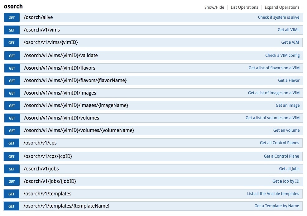
This figure shows the list of Get APIs that can be used to query the database.
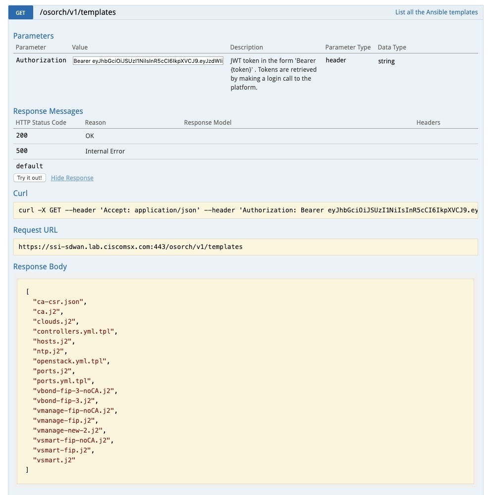
This figure shows a sample query to access the list of templates from the OS orchestrator using the curl command in this GET API page
Troubleshooting the OS orchestrator Logs
To access the OS orchestrator logs:
Procedure
| Step 1 |
Log in to the Kubernetes-master mode. |
| Step 2 |
Execute the given command to get the OS orchestrator pod name: |
| Step 3 |
To log in to the container, execute the given command: |
| Step 4 |
To check the logs, execute the given command: jobID: Specifies the job ID to access the specific job. If there are errors during the creation of a control plane these logs can offer some guidance, it verifies the incorrect parameters and ways to resolve issues. |
Change Control Plane Password or Vault Failures
Error Message
Failed to authenticate control plane user.
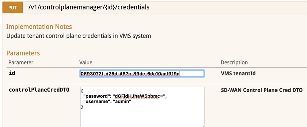
Solution
Use the Swagger interface to update the credentials for the control plane manager. The password input in base64.
Fixing Control Plane Device Status State
Problem
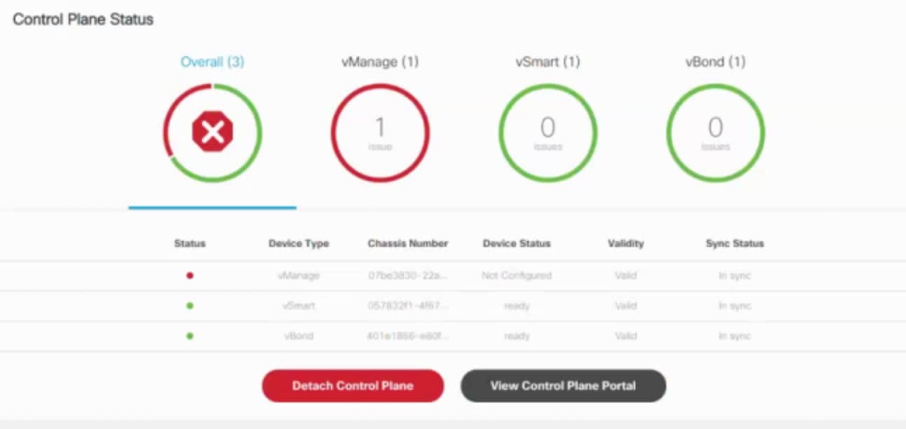
After adding a new control plane, the Control Plane (vManage) remains in ‘Not Configured’ state, as shown below:
Reason
Incorrect way of changing the control plane password. This issue was due to changing the Control Plane password from vManage Console > Configuration > Devices > Controllers.
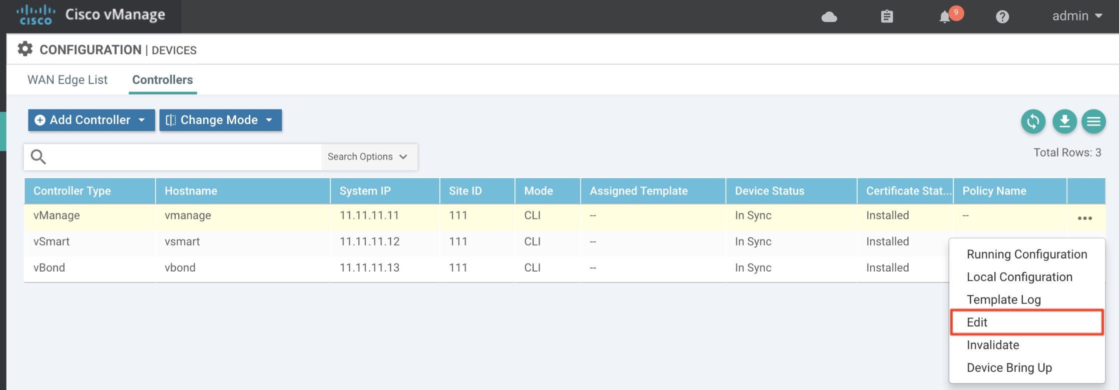
Solution
Procedure
| Step 1 |
Change the Control Plane password from vManage Console > Administration > Manage Users > Users. 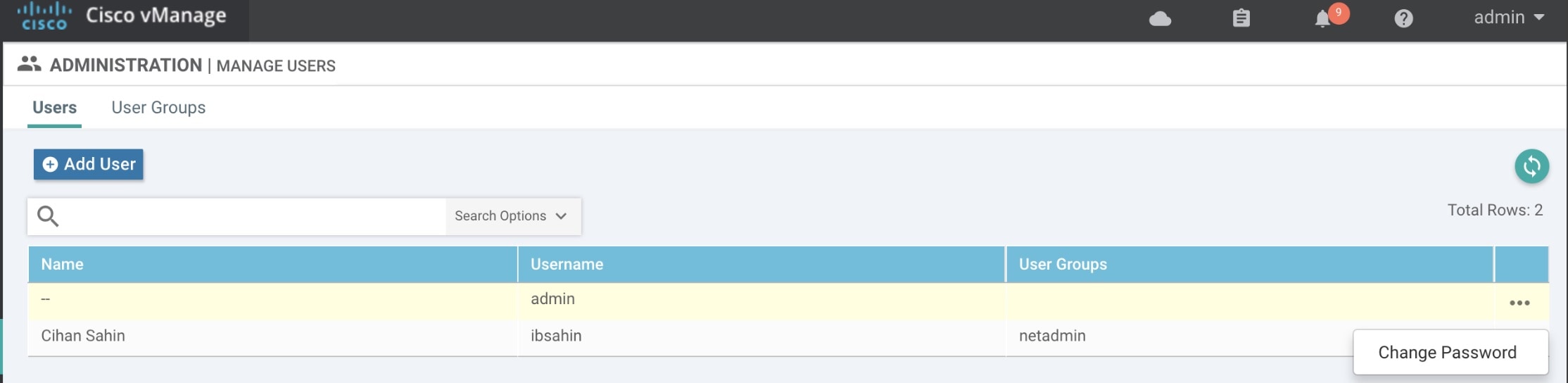
|
||
| Step 2 |
Restart nms application server on vManage.
|
Data Plane Troubleshooting
Check the deployment status of the vEdge device:
-
Check NSO device status.
-
Check data plane deployment i4e n the Cisco MSX Portal.
Check the reachability status (vEdge to control plane):
-
Check the vManage device state.
-
Check that the site status in SD-WAN is green.
Data Plane Deployment Status: NSO Device Status
Example:
vmsnso@ncs> show branch-infra:branch-infra-status branch-cpe agH89ZqVcqVObci6Pyv1jU56 plan component state
NAME                            STATE         STATUS   WHEN                 ref  MESSAGE
------------------------------------------------------------------------------------------
self                            init          reached  2017-11-12T04:55:12  -
                                ready         reached  2017-11-12T04:57:33  -
agH89ZqVcqVObci6Pyv1jU56        init          reached  2017-11-12T04:55:12  -
                                pnp-callhome  reached  2017-11-12T04:55:12  -
                                ready         reached  2017-11-12T04:56:10  -    Ready
vEdge_SD-Branch-vEdge           init          reached  2017-11-12T04:56:11  -
                                ready         reached  2017-11-12T04:56:34  -    Ready
vEdge_agH89ZqVcqVObci6Pyv1jU56  init          reached  2017-11-12T04:56:35  -
                                vm-deployed   reached  2017-11-12T04:56:50  -
                                vm-alive      reached  2017-11-12T04:57:33  -
                                ready         reached  2017-11-12T04:57:33  -    Ready
Data Plane Deployment Status (Cisco MSX Portal)
To view the data plane deployment status:
Procedure
| Step 1 |
Log in to the Cisco MSX Portal. |
| Step 2 |
In the main menu, click Dashboard. |
| Step 3 |
Select the tenant from the drop-down. |
| Step 4 |
Click SD-WAN. The SD-WAN Service Offer screen appears. |
| Step 5 |
Click SD-WAN. |
| Step 6 |
Select the SD-WAN service. The SD-WAN screen appears. |
Data Plane Reachability Status (Cisco MSX Portal)
To view the data plane reachability status:
Procedure
| Step 1 |
Log in to the Cisco MSX Portal. |
| Step 2 |
In the main menu, click Dashboard. |
| Step 3 |
Select the tenant from the drop-down. |
| Step 4 |
Click SD-WAN. The SD-WAN Service Offer screen appears. |
| Step 5 |
Click SD-WAN. |
| Step 6 |
Select the SD-WAN service. The SD-WAN screen appears. |
Reachability Status: vManage Device State
To view the reachability status:
Procedure
| Step 1 |
Log in to vManage. |
| Step 2 |
In vManage, choose Configuration > Devices.The Configure | Devices window is displayed. 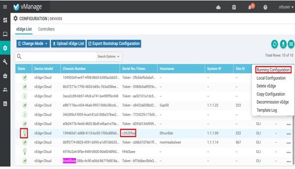
|
PnP Server Troubleshooting Commands
List of Devices in Contact with the PnP Server
admin@ncs-sm-SD-Branch> show pnp list
SERIAL        IP ADDRESS       CONFIGURED  ADDED  SYNCED  LAST CONTACT
-------------------------------------------------------------------------------
FTX1738AJME   173.36.207.85    true        true   true    2017-10-24 23:44:44
FTX1738AJMG   173.36.207.81    true        true   true    2017-10-24 23:43:50
FTX1740ALBX   173.36.207.80    true        true   true    2017-10-24 23:44:21
SSI184904LG   173.36.207.82    true        true   true    2017-10-24 23:43:56
SSI185104LT   173.36.207.84    true        true   true    2016-10-24 23:43:57
[ok][2016-10-24 23:45:49]
Note |
|
CPE in Contact with the PnP Server (Without a Service)
admin@ncs-sm-SD-Branch> show branch-infra:branch-infra branch-cpe
%No entries found
[ok][2016-10-24 23:45:49]
CPE in Contact with the PnP Server (With a Service)
admin@ncs-sm-SD-Branch> show branch-infra:branch-infra-status branch-cpe amXqvXDO9zW2IZleho2cOBrD plan component state status
NAME                      STATE         STATUS
-------------------------------------------------
self                      init          reached
                          ready         reached
amXqvXDO9zW2IZleho2cOBrD  init          reached
                          pnp-callhome  reached
                          ready         reached
[ok][2017-10-25 14:20:40]
CPE in Contact with the PnP Server (Detailed)
vmsnso@ncs> show branch-infra:branch-infra-status branch-cpe amXqvXDO9zW2IZleho2cOBrD plan component
plan component self
 type      self
 state init
  status  reached
  when    2017-10-25T14:15:20
  message ""
 state ready
  status  reached
  when    2017-10-25T14:16:57
  message ""
 real-name amXqvXDO9zW2IZleho2cOBrD
plan component amXqvXDO9zW2IZleho2cOBrD
 type      branch-cpe
 state init
  status  reached
  when    2017-10-25T14:15:20
  message ""
 state pnp-callhome
  status  reached
  when    2017-10-25T14:16:22
  message ""
 state ready
  status  reached
  when    2017-10-25T14:16:57
  message Ready
 real-name amXqvXDO9zW2IZleho2cOBrD
 provider  CiscoSystems
 device    amXqvXDO9zW2IZleho2cOBrD_ENCS
[ok][2017-10-25 14:23:10]
View CPE Details
vmsnso@ncs> show pnp list
SERIAL       IP ADDRESS    CONFIGURED  ADDED  SYNCED  LAST CONTACT
---------------------------------------------------------------------------
FGL21388017  10.85.189.20  true        true   true    2017-10-25 14:24:07
FGL2138801A  10.85.189.23  false       false  false   2017-10-25 14:21:16
FGL2138801E  10.85.189.24  false       false  false   2017-10-25 14:21:40

[ok][2017-10-25 14:24:20]
vmsnso@ncs> configure
Entering configuration mode private
[ok][2017-10-25 14:24:31]

[edit]
vmsnso@ncs% show branch-infra:branch-infra branch-cpe serial FGL21388017
branch-cpe amXqvXDO9zW2IZleho2cOBrD {
    provider CiscoSystems;
    type     ENCS;
    serial   FGL21388017;
    var SD-Branch_DEVICE_TYPE {
        val ENCS;
    }
    var contact {
        val Customer;
    }
    var email {
        val abc@example.ocm;
    }
    var phone {
        val null;
    }
}
[ok][2017-10-25 14:24:34]
[edit]
vmsnso@ncs% exit
[ok][2017-10-25 14:24:53]
IPsec Tunnel Cannot be Established
Problem
Device fails to establish secure VPN tunnel between NFVIS and CSR Mgmt hub router.
Solution
To establish secure VPN tunnel:
Procedure
| Step 1 |
Log in to the device and run the following command: Example: |
| Step 2 |
Ensure day0-common has correct values specified for the following parameters: Example: |
| Step 3 |
Ensure CSR Hub VPN configuration matches NFVIS's. |
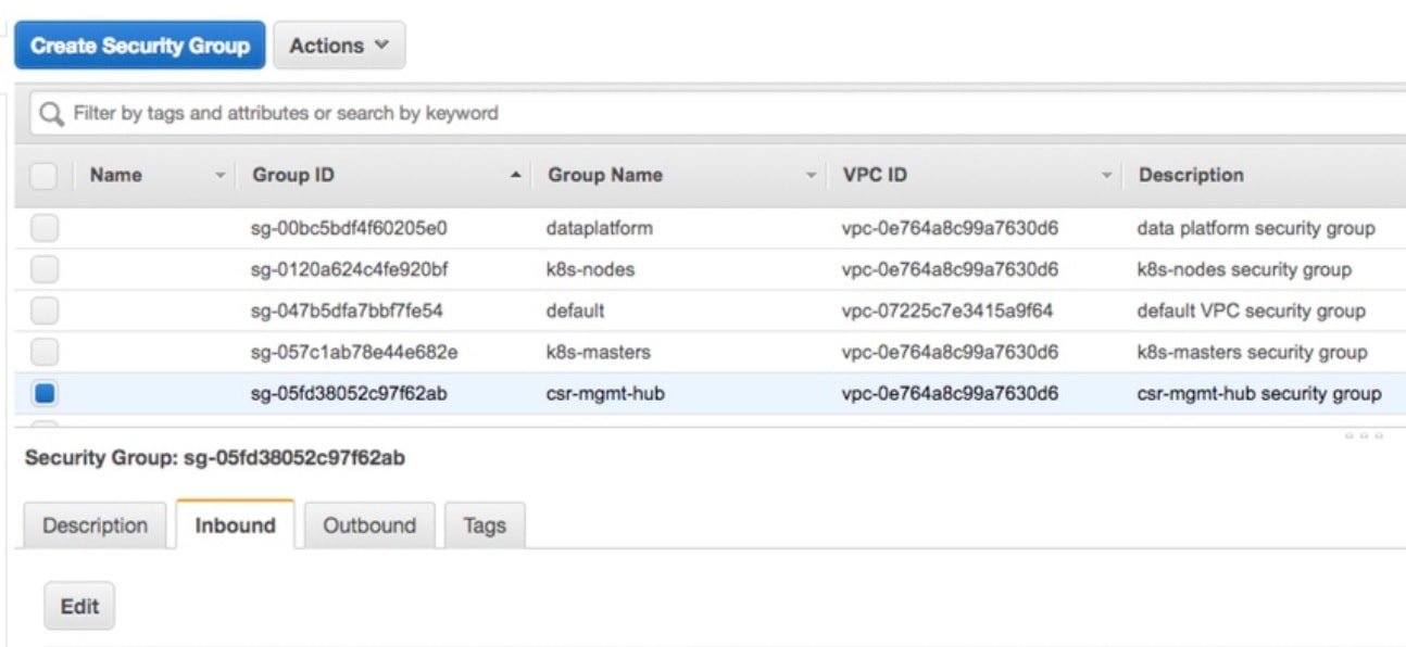
| Step 4 |
Edit CSR Hub’s Security group and ensure the following ports are open. The following ports are used for communication from Cisco MSX to the NFVIS via the CSR mgmt hub VPN.
|
| Step 5 |
Configure route to NFVIS's secure IP. The default is 10.128.0.0/16 (Assigned by SD-Branch). This can be changed using:
|
Applications Available with Cisco MSX SD-WAN
Cisco MSX allows you to set the application relevance for the applications in Cisco SD-WAN managed sites. For more information, see Cisco Managed Services Accelerator (MSX) 4.3 SD-WAN Out-of-the-Box Applications Addendum.
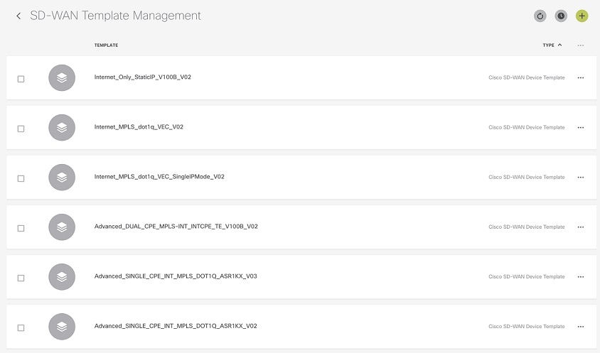
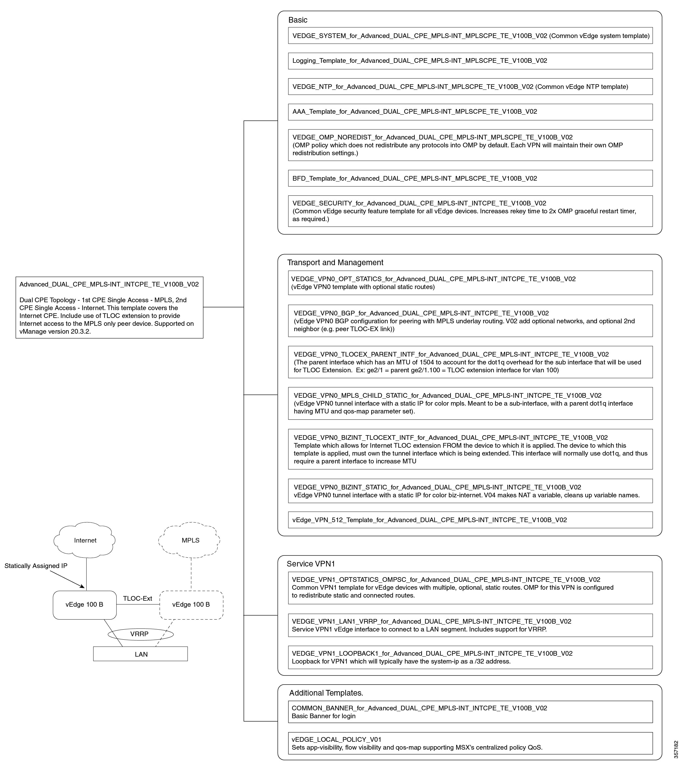
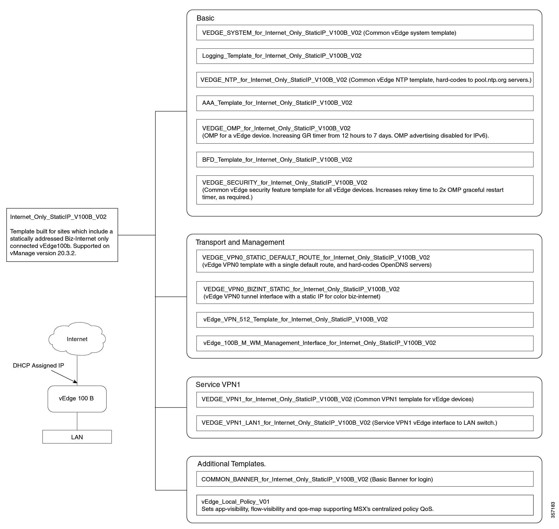
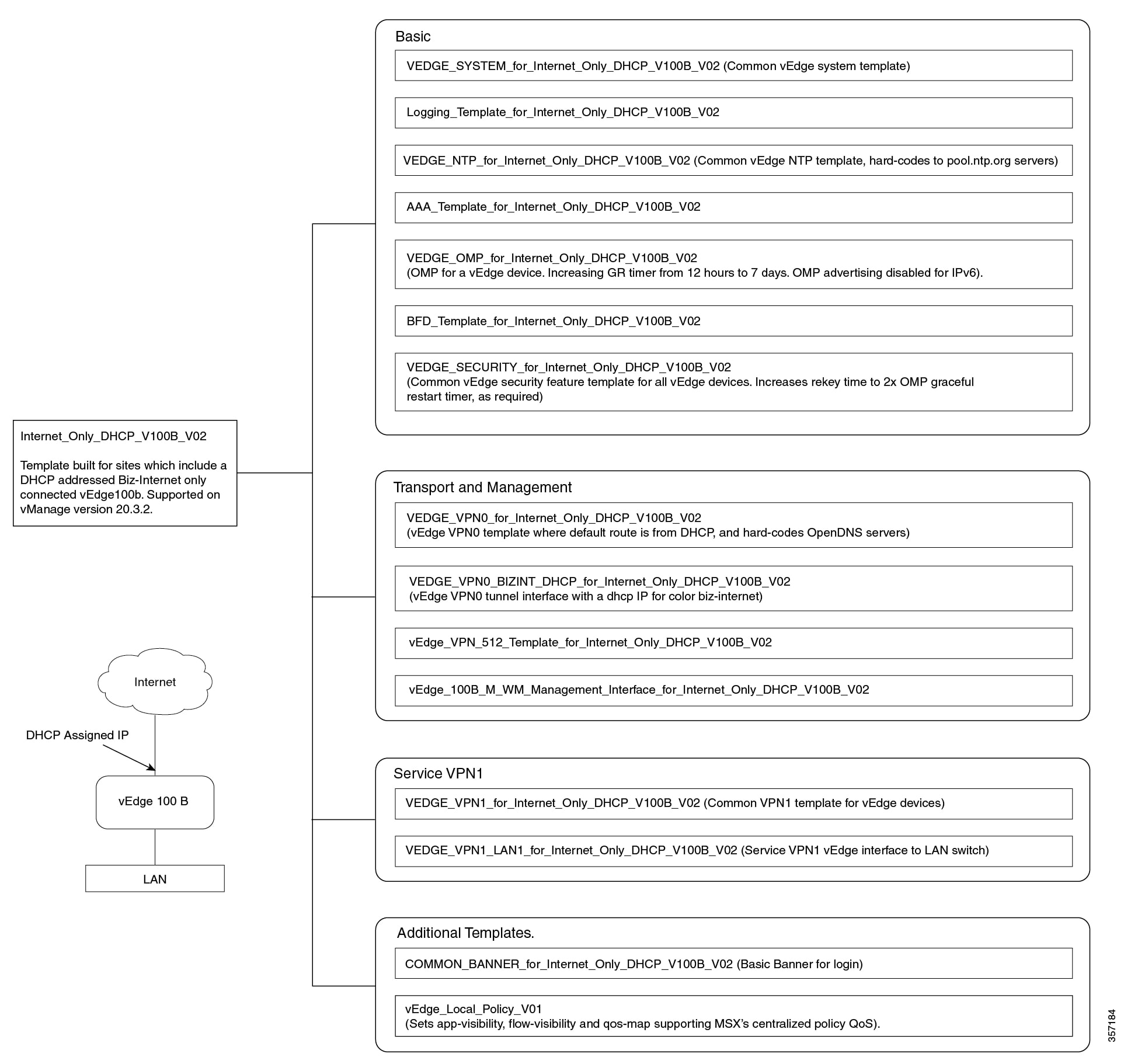
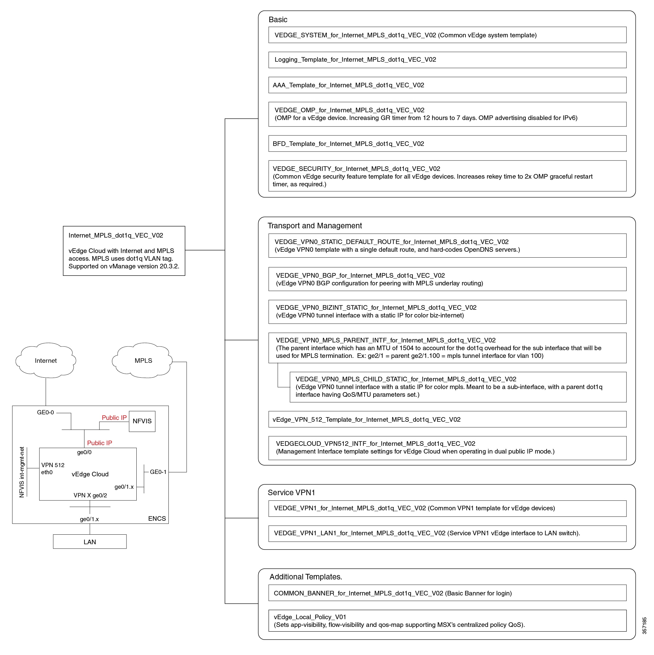
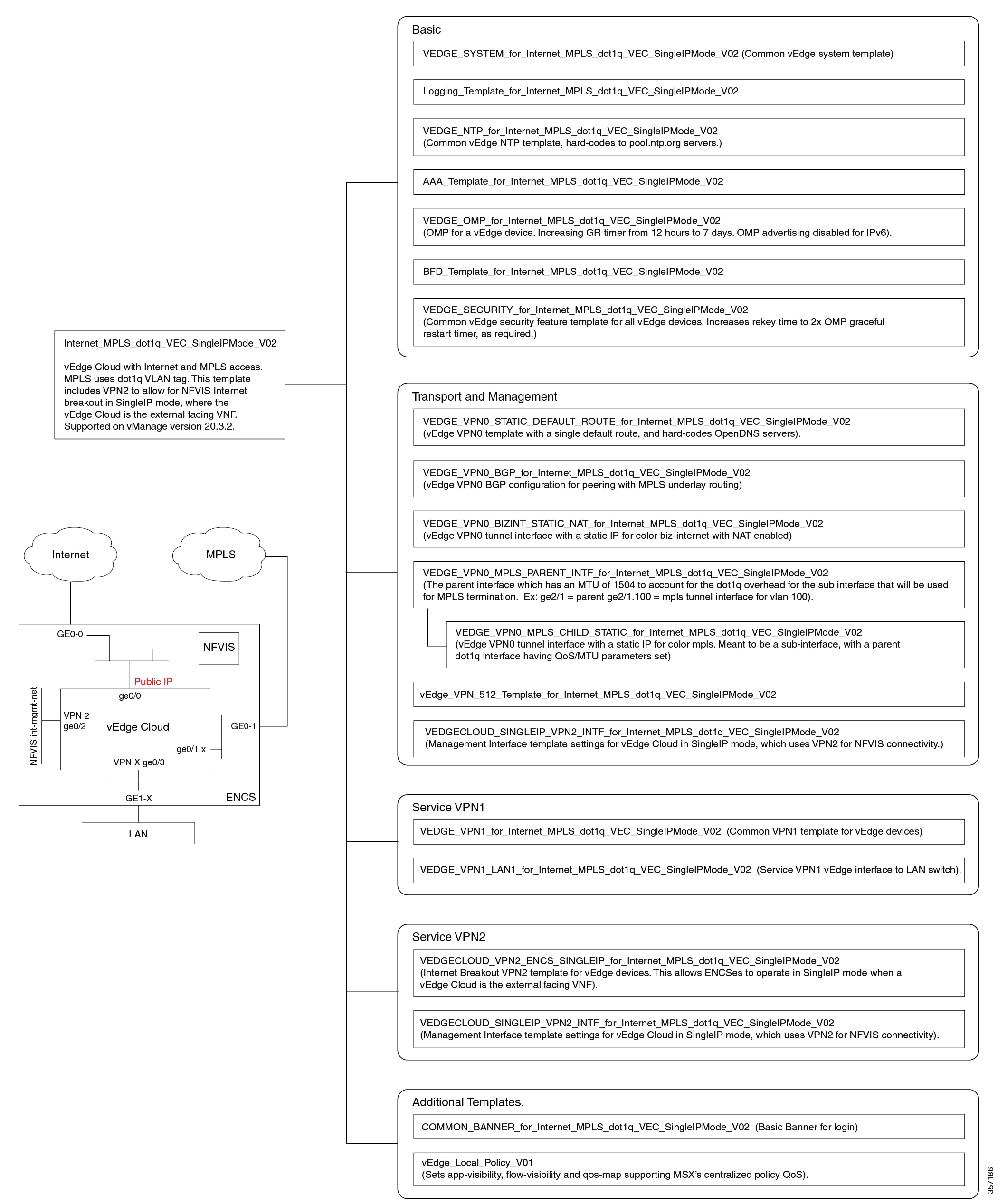
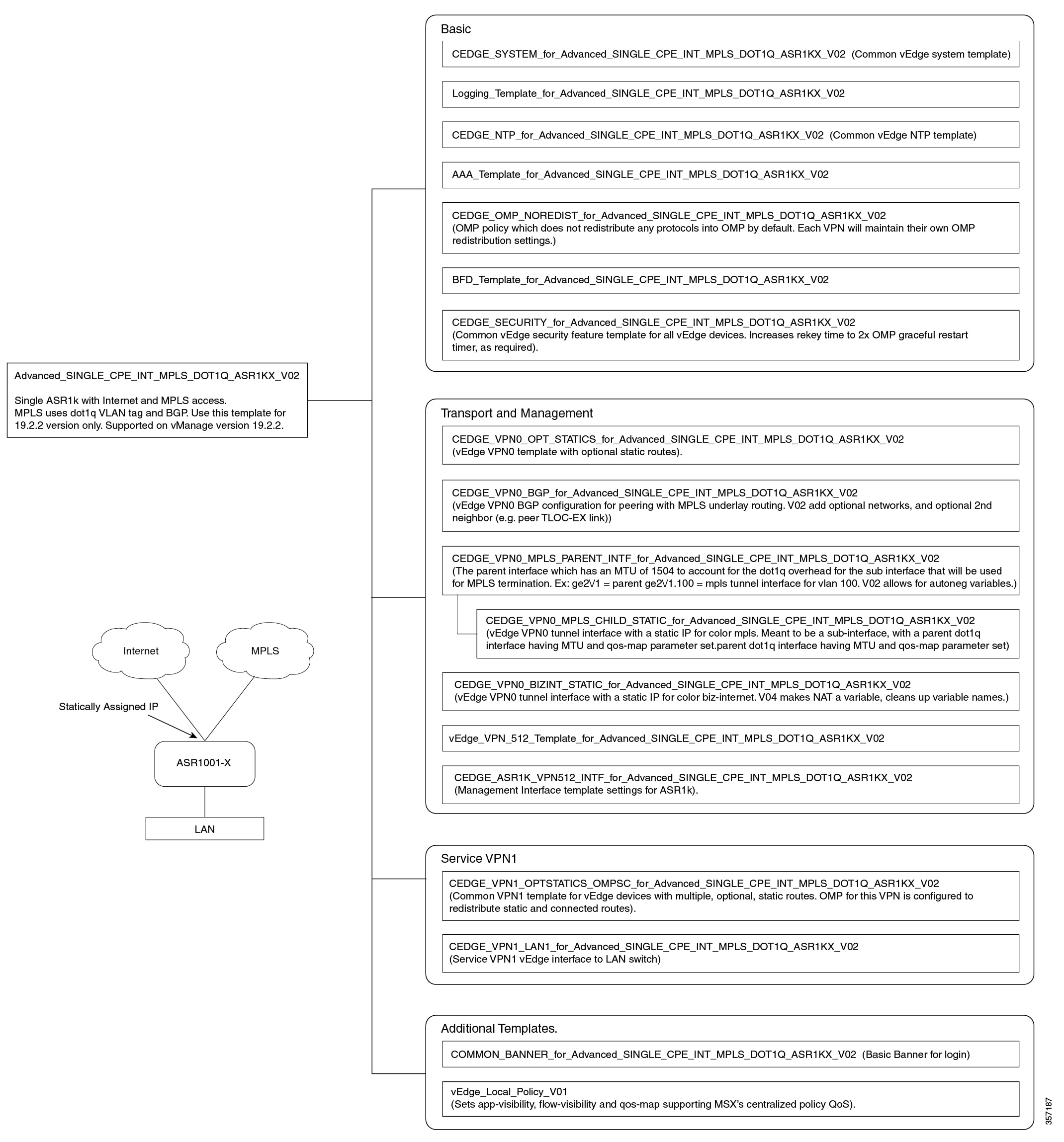
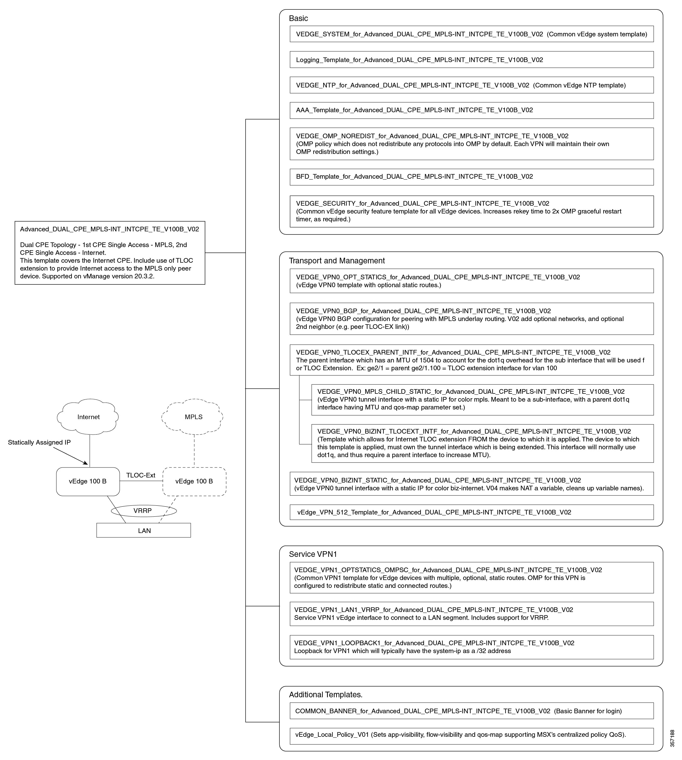
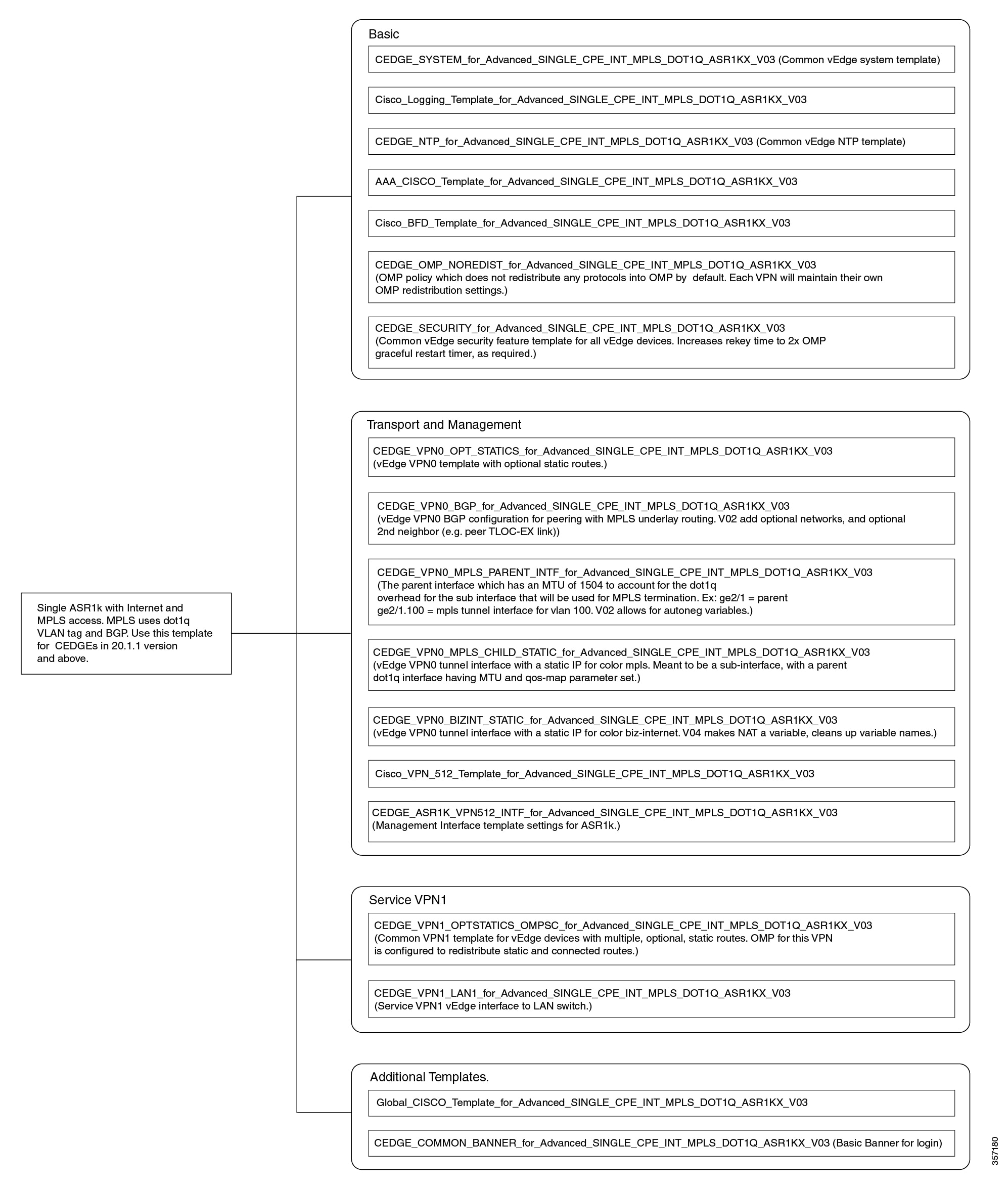
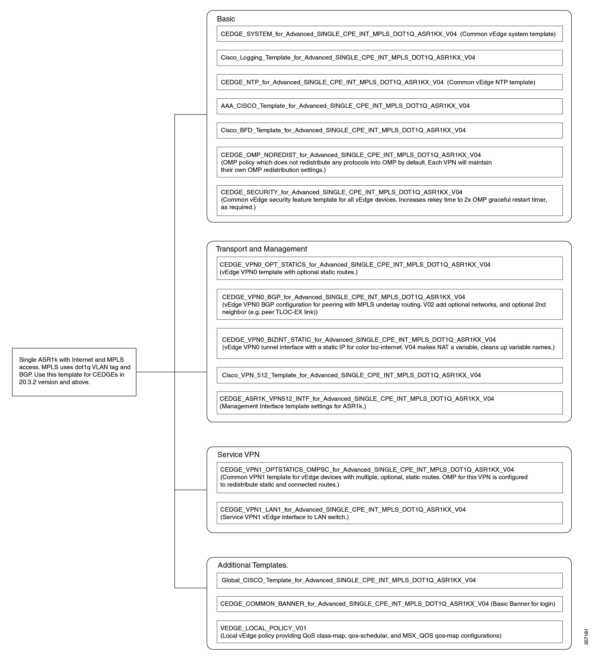
Out-of-the-Box Cisco SD-WAN Device Templates Available Within Cisco MSX
Cisco MSX provides out-of-the-box device templates. The details of these templates are provided in the figures below. You can export these templates to your tenants vManage and use them as it is or modify them as per your requirements.
Note |
After the upgrade, the Cisco MSX SD-WAN out-of-the-box device templates assigned to your tenants will continue to work. However, if you are assigning templates to the tenants, use the new out-of-the-box templates (template names with V02 or V03 or V04). If you assign old templates, the system will show an error indicating that these are outdated OOB templates. |
Sample Payloads for Creating Cisco SD-WAN Control Plane on Openstack
This section contains the sample JSON configuration files for adding VIM and control plane payloads in the provider and tenant network. The authentication certificate is a part of the control plane deployment activity in vManage and sample JSON files are given for both enterprise and symantec certificate based on the network.
Adding VIM Payload in Provider Network
This is the sample JSON file for adding VIM payload in the provider network.
Note:
-
Ensure that the names used in "dtlsNetName"(VPN0) and "mgmtNetName"(VPN512) are from the provider network, that is already created in the OpenStack cloud.
-
The VPN512 network should be reachable from Cisco MSX for the deployment of the control plane.
-
The VPN0 network should be reachable from vEdge for the deployment of vEdge on the deployed control plane.
Provider Network.json
#Provider
{
"tenantID": "TestTenant",
"vim":
{
"type": "openstack",
"openstack":
{
"username": "username",
"password": "password",
"authURL": "URL",
"projectName": "admin",
"projectID": Project ID,
"domainName": "Default",
"region": "RegionOne",
"extNetName": "external",
"networkType": "provider",
"network":
{
"dtlsNetName": "Vnf-outside",
"mgmtNetName": "external"
}
}
}
}
Adding VIM Payload in Tenant Network
This is the sample JSON file for adding VIM payload in tenant network.
Note:
-
Ensure that the names used in "dtlsNetName"(VPN0) and "mgmtNetName"(VPN512) are not repeated on the openstack cloud.
-
The subnet used in "dtlsSubnet"(VPN0) and "mgmtSubnet"(VPN512) for the 'create control plane' payload should not be repeated on the openstack cloud. You can provide two subnets in this payload.
-
The VPN512 network has floating IPs that should be reachable from Cisco MSX for the deployment of the control plane.
-
The VPN0 network has floating IPs that should be reachable from vEdge for the deployment of vEdge on the deployed control plane.
Tenant Network.json
{
"tenantID": "TestTenant",
"vim": {
"type": "openstack",
"openstack": {
"username": "username",
"password": "password",
"authURL": "url",
"projectName": "admin",
"projectID": "Project ID",
"domainName": "Default",
"region": "RegionOne",
"extNetName": "external",
"networkType": "tenant",
"network": {
"dtlsNetName": "Test-Dtls",
"mgmtNetName": "Test-Mgmt"
}
}
}
}
Adding Control Plane Payload with Enterprise Certificate in Provider Network
This is the sample JSON file for adding control plane payload with enterprise certificate in provider network.
Provider Network with EnterpriseCA.json
{
"tenantID": "TestTenant",
"controlPlane": {
"vimID": "vimID",
"vmanage": {
"flavor": "viptela-vmanage-vm",
"image": "viptela-vmanage-19.1.0-genericx86-64.qcow2",
"hostname": "TestManage01",
"systemID": "system ID",
"day0": "vmanage-fip.j2",
"vpn0": {
"publicIP": "IP address",
"gateway": "IP address",
"subnetMaskBits": "24"},
"vpn512": {
"publicIP": "IP address",
"gateway": "IP address",
"subnetMaskBits": "24"
}
},
"vbond": {
"flavor": "viptela-vbond-vm",
"image": "viptela-edge-19.1.0-genericx86-64.qcow2",
"hostname": "TestBond01",
"systemID": "system ID",
"day0": "vbond-fip-3.j2",
"vpn0": {
"publicIP": "IP address",
"gateway": "IP address",
"subnetMaskBits": "24"
},
"vpn512": {
"publicIP": "IP address",
"gateway": "IP address",
"subnetMaskBits": "24"
}
},
"vsmart": {
"flavor": "viptela-vsmart-vm",
"image": "viptela-smart-19.1.0-genericx86-64.qcow2",
"hostname": "TestSmart01",
"systemID": "system ID",
"day0": "vsmart-fip.j2",
"vpn0": {
"publicIP": "IP address",
"gateway": "IP address",
"subnetMaskBits": "24"
},
"vpn512": {
"publicIP": "IP address",
"gateway": "IP address",
"subnetMaskBits": "24"
}
},
"credentials": {
"username": "username",
"password": "password"
},
"org": "vmsoverlay1",
"siteID": "site ID",
"ntpServer": "ntp.esl.cisco.com",
"dnsServer": "dns serverIP address",
"createCA": true
}
}
Adding Control Plane Payload with Symantec Certificate in Provider Network
This is the sample JSON file for adding control plane payload with symantec certificate in provider network.
Provider Network with Symantec.json
{
"tenantID": "TestTenant",
"controlPlane": {
"vimID": "vim ID",
"vmanage": {
"flavor": "viptela-vmanage-vm",
"image": "viptela-vmanage-19.1.0-genericx86-64.qcow2",
"hostname": "TestManage01",
"systemID": "system ID",
"day0": "vmanage-fip-noCA.j2",
"vpn0": {
"publicIP": "IP address",
"gateway": "IP address",
"subnetMaskBits": "24"
},
"vpn512": {
"publicIP": "IP address",
"gateway": "IP address",
"subnetMaskBits": "24"
}
},
"vbond": {
"flavor": "viptela-vbond-vm",
"image": "viptela-edge-19.1.0-genericx86-64.qcow2",
"hostname": "TestBond01",
"systemID": "system ID",
"day0": "vbond-fip-3-noCA.j2",
"vpn0": {
"publicIP": "IP address",
"gateway": "IP address",
"subnetMaskBits": "24"
},
"vpn512": {
"publicIP": "IP address",
"gateway": "IP address",
"subnetMaskBits": "24"
}
},
"vsmart": {
"flavor": "viptela-vsmart-vm",
"image": "viptela-smart-19.1.0-genericx86-64.qcow2",
"hostname": "TestSmart01",
"systemID": "system ID",
"day0": "vsmart-fip-noCA.j2",
"vpn0": {
"publicIP": "IP address",
"gateway": "IP address",
"subnetMaskBits": "24"
},
"vpn512": {
"publicIP": "IP address",
"gateway": "IP address",
"subnetMaskBits": "24"
}
},
"credentials": {
"username": "username",
"password": "password"
},
"org": "vmsoverlay1",
"siteID": "site ID",
"ntpServer": "ntp.esl.cisco.com",
"dnsServer": "IP address",
"createCA": false
}
}
Adding Control Plane Payload with Enterprise Certificate in Tenant Network
This is the sample JSON file for adding control plane payload with enterprise certificate in tenant network.
Tenant Network with EnterpriseCA.json
{
"tenantID": "TestTenant",
"controlPlane": {
"vimID": "vim ID",
"vmanage": {
"flavor": "viptela-vmanage-vm",
"image": "viptela-vmanage-19.1.0-genericx86-64.qcow2",
"hostname": "TestManage10",
"systemID": "system ID",
"day0": "vmanage-fip.j2",
"vpn0": {
"subnetMaskBits": "24"
},
"vpn512": {
"subnetMaskBits": "24"
}
},
"vbond": {
"flavor": "viptela-vbond-vm",
"image": "viptela-edge-19.1.0-genericx86-64.qcow2",
"hostname": "TestBond10",
"systemID": "50.0.1.11",
"day0": "vbond-fip-3.j2",
"vpn0": {
"subnetMaskBits": "24"
},
"vpn512": {
"subnetMaskBits": "24"
}
},
"vsmart": {
"flavor": "viptela-vsmart-vm",
"image": "viptela-smart-19.1.0-genericx86-64.qcow2",
"hostname": "TestSmart10",
"systemID": "system ID",
"day0": "vsmart-fip.j2",
"vpn0": {
"subnetMaskBits": "24"
},
"vpn512": {
"subnetMaskBits": "24"
}
},
"credentials": {
"username": "username",
"password": "password"
},
"org": "vmsoverlay1",
"siteID": "site ID",
"ntpServer": "ntp.esl.cisco.com",
"dnsServer": "IP address",
"createCA": true,
"dtlsSubnet": "IP address",
"mgmtSubnet": "IP address"
}
}
Adding Control Plane Payload with Symantec Certificate on Tenant Network
This is the sample JSON file for adding control plane payload with symantec certificate on tenant network.
Tenant Network with Symantec.json
{
"tenantID": "TestTenant",
"controlPlane": {
"vimID": "vim ID",
"vmanage": {
"flavor": "viptela-vmanage-vm",
"image": "viptela-vmanage-19.1.0-genericx86-64.qcow2",
"hostname": "TestManage10",
"systemID": "system ID",
"day0": "vmanage-fip-noCA.j2",
"vpn0": {
"subnetMaskBits": "24"
},
"vpn512": {
"subnetMaskBits": "24"
}
},
"vbond": {
"flavor": "viptela-vbond-vm",
"image": "viptela-edge-19.1.0-genericx86-64.qcow2",
"hostname": "TestBond10",
"systemID": "system ID",
"day0": "vbond-fip-3-noCA.j2",
"vpn0": {
"subnetMaskBits": "24"
},
"vpn512": {
"subnetMaskBits": "24"
}
},
"vsmart": {
"flavor": "viptela-vsmart-vm",
"image": "viptela-smart-19.1.0-genericx86-64.qcow2",
"hostname": "TestSmart10",
"systemID": "system ID",
"day0": "vsmart-fip-noCA.j2",
"vpn0": {
"subnetMaskBits": "24"
},
"vpn512": {
"subnetMaskBits": "24"
}
},
"credentials": {
"username": "username",
"password": "password"
},
"org": "vmsoverlay1",
"siteID": "site ID",
"ntpServer": "ntp.esl.cisco.com",
"dnsServer": "IP address",
"createCA": false,
"dtlsSubnet": "IP address",
"mgmtSubnet": "IP address"
}
}
![]()
 Feedback