Inventory Manager
Available Languages
Table Of Contents
Using the Network Inventory Manager
Understanding the Network Inventory Window
Working with Subnetworks and Complexes
Specifying Protocol Attributes for a Subnetwork
Specifying Call Agent Attributes for a Subnetwork
Specifying Connectivity Attributes for a Subnetwork
Specifying Terminal Server Attributes for a Subnetwork
Specifying Aggregator Attributes
Specifying Protocol Attributes for a Complex
Specifying Call Agent Attributes
Specifying Connectivity Attributes for a Complex
Specifying Terminal Server Attributes for a Complex
Viewing and Modifying Subnetwork or Complex Properties
Viewing and Modifying Aggregator Properties
Provisioning a New CPE Device for an ESR10K Complex
Refreshing the Server Configuration
Viewing and Modifying Telnet Gateway Properties
Viewing and Modifying Element Properties
Viewing and Modifying Terminal Server Attributes for a CPE
Generating and Downloading a Configuration File to a CPE
Downloading a Configuration Using a Telnet Gateway
Deleting Provisioning of CPE Device
Deleting a Service for a CPE Device
Deleting a Channel for a CPE Device
Setting Up the Automatic Configuration Feature
Configuring Routers to Communicate with the Cisco IE2100
Ensuring That the Complex Properties Page Has the Correct Cisco IE2100 Name
Establishing the Connection Between the IAD2421 and the Cisco IE2100
Using the Network Inventory Manager
The Network Inventory Manager allows you to create, query, modify, and delete your network inventory and provision the supported devices. It allows you to set up the download method for downloading a configuration and its authentication to a specific device.
Understanding the Network Inventory Window
The Network Inventory Manager Tree View displays a hierarchical view of the network and CPEs inventoried in the Cisco Convergent Network Solution Center: Subscriber Provisioning Repository. The inventoried objects can include:
•
Network partitions in the form of subnetworks and complexes (MGX and ESR10K complexes)
•
•
•
•

Note
From the Network Inventory Manager Tree View, you can create your network inventory or you can select an existing inventoried object that you want to manage. Figure 3-1 shows an expanded view of the CCNSC Subscriber Provisioning Network Inventory Manager Tree View.
Figure 3-1 Network Inventory Manager—Expanded Window
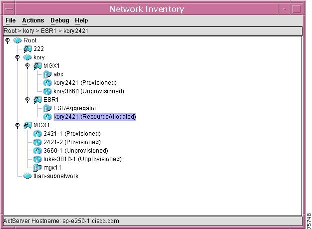
The Network Inventory window also provides the Tree View menu bar, which allows you to select various operations to perform from several drop-down menus. You can also select an operation from a context menu by right-clicking on the icon within the Tree View. The Tree View menu bar provides the following drop-down menus:
Table 3-1 Tree View Menu Options
File
Allows you to close the Network Inventory Manager. The Close option stops the Network Inventory Manager process.
Actions
Allows you to perform the following operations:
Refresh—provides four options:
•
•
•
•
Subnetwork—creates subnetworks and other complexes. This option is enabled when a subnetwork is selected.
Aggregator Complex—identifies the operations that can be performed for a selected aggregator complex. This option is enabled when an aggregator complex is enabled.
Device—identifies all of the operations that can be performed for a selected device. This option is enabled when a device is selected.
The operations that are enabled within these drop-down menus depend upon whether or not the particular network element exists. If it exists, all operations are enabled. If it does not exist, the operations are disabled and appear gray.
Debug
Allows you to set the debug level for the CCNSC Subscriber Provisioning Client and the CCNSC Subscriber Provisioning Server. For information about the possible debug levels and their meanings, see the "Setting Debug Levels" section.
The Network Tree shows all of the objects that are currently defined in CCNSC Subscriber Provisioning. The Network Tree uses the following conventions:
•
icon to indicate that the tree can be expanded. Click the icon to expand to the next level of the hierarchy.
When the Network Tree first appears (or when refreshed), you must click on an item the first time for the
The
icon indicates that you have reached the lowest level in the hierarchy for that network object. Click the icon to collapse to the previous level of the hierarchy.
•
icon. The root is the highest level network object and can be made up of any number of subnetworks and complexes.
•
icon. A subnetwork is a logical partition of your network and can optionally be made up of any number of other subnetworks and Complexes. Subnetworks are arbitrarily determined by a network administrator in order to provide a multilevel hierarchical structure.
•
icon. A Complex is a logical partition of your network. A Complex can be created subordinate to a subnetwork or can be created to be at the same hierarchical level as a Subnetwork. A Complex is arbitrarily determined by a network administrator in order to provide a multilevel hierarchical structure.
•
icon. An aggregator is a device that aggregates data from a number of devices that are connected to the aggregator. An aggregator can be created subordinate to a complex.
•
icon. A device can be subordinate to a Subnetwork or a Complex. Devices that are subordinate to a MGX Complex are Cisco 2421s, Cisco 3810s, or Cisco 3660s. Objects that are subordinate to an ESR10K Complex are Cisco 2421s. A device defined for the subnet or a Complex can be a new device or a deployed device. A new device means that you are creating it for the first time. A deployed device is an existing device that has been provisioned outside of CCNSC Subscriber Provisioning but you want to bring it under the management of CCNSC Subscriber Provisioning. The current state of the device is shown in parentheses, such as Unprovisioned, ResourceAllocated, and Provisioned. For more information about device states and transitions, see the "Device States and Transitions" section. Devices are at the customer site. This is the lowest level network object displayed in the Network Tree.
•
icon. These devices are subordinate to a Subnetwork. A device is part of the core network. This is the lowest level network object displayed in the Network Tree.
To be managed by the Network Inventory Manager, the network object must be listed in the Network Tree. If the network object is not listed, try expanding the hierarchy. If it is still not listed, it has not been inventoried in the CCNSC Subscriber Provisioning Repository. If it is a network element that you want to manage, you can create it or bring it under CCNSC Subscriber Provisioning management.
Working with the Root Node
The Root node is the highest level network object and can be made up of any number of subnetworks and complexes. The actions available for the Root node are as follows and are described in these sections:
•
•
•
Working with Subnetworks and Complexes
A subnetwork is a logical partition of your network and can optionally be made up of any number of other subnetworks. A complex is a group of devices that feed data to an ESR10K or an MGX device. Subnetworks are arbitrarily determined by a network administrator in order to provide a multilevel hierarchical structure. The actions available for subnetworks are as follows:
•
•
•
•
•
•
Creating a Subnetwork
When you create a subnetwork, you are arbitrarily segmenting your network to provide a multilevel, hierarchical routing structure while shielding the subnetwork from the addressing complexity of attached networks. You can create a subnetwork to be directly subordinate to the Root node or to another subnetwork.
Procedure
Step 1
Step 2
The Create Subnetwork window appears, with the Subnetwork tab enabled, as shown in Figure 3-2.
Figure 3-2 Create Subnetwork Window

Step 3
Step 4
You can specify the following subnetwork types:
•
The Network Inventory Manager automatically retrieves and selects the configured values of the Parent, Configuration Delivery Servers, Call Agent, and Resource Allocation Servers from various configuration files. If more than one value is configured for a particular field, you can select from a drop-down list. The Parent and Call Agent information always have only one value, therefore, you do not need to select a value for these fields.
Step 5
The parent for the network object you are creating is automatically provided for you based on the Root node or subnetwork under which you are creating this network object. This identifies the Network Inventory Manager Root as it is defined in the ACT server. The top level parent is always /Root. You cannot select a different value.
Step 6
Step 7
A domain is a portion of the naming hierarchy tree that refers to general groupings of networks based on organization-type or geography. This domain name must be configured to match the one defined in DNS.
Step 8
The Configuration Delivery Manager will send the configuration for downloading onto the device using this Telnet Gateway. The Network Inventory Manager retrieves this information from the /opt/CSCOcnscs/cdm/cdm.properties file. The Telnet Gateway method can be used for downloading configurations to devices. If you select this method, you must also define terminal server attributes and connectivity attributes.
Step 9
You are now ready to specify protocol attributes for the subnetwork.
Specifying Protocol Attributes for a Subnetwork
Step 1
The Protocol tab is enabled. There are two subtabs in this window—the ATM tab and the IP tab.
Step 2
See the following sections for specific information:
•
•
Step 3
Clicking Create saves attributes in all of the tabs and closes the window. Only the fields in the Subnetwork Attributes tab are required to create a subnetwork. If you wish to fill in values for other tabs, wait to click Create until you have filled them all in.
To specify other attributes for the subnetwork, see the following sections:
•
•
Step 4
Specifying ATM Attributes for a Subnetwork
Step 1
The ATM tab is enabled, as shown in Figure 3-3.
Figure 3-3 Create Subnetwork - ATM Window

Step 2
The Cisco Network Registrar provides a DHCP service and DNS. CNR clients can use CNR to obtain their IP address assignments and other configuration information through the DHCP service, and DNS is used to resolve the IP addresses to a hostname. The Network Inventory Manager retrieves this information from the ipservice.cfg file.
Step 3
The group name collectively identifies the IP addresses (IP address pools) within this subnetwork that are to be allocated for voice signaling and bearer PVCs. For example, MGX1. The Network Inventory Manager retrieves this information from the /CSCOcnscs/resourceMgr/common/ipservice.cfg file.
Step 4
The Signal and Bearer DHCP scopes that you select must be in the same group.The Signal DHCP scope identifies the name of the IP address pool, IP address range, and subnet mask that are to be used for IP address allocation for voice signaling. The GUI displays the information in the following format:
<scope name> <IPaddress>-<IP address> <subnetmask>
For example:
signal 101.32.104.50-102.32.104.100 255.255.255.0The Network Inventory Manager retrieves this information from the /CSCOcnscs/resourceMgr/common/ipservice.cfg file.
Step 5
The Signaling and Bearer DHCP scopes that you select must be in the same group.The Bearer DHCP scope identifies the name of the IP address pool, IP address range, and subnet mask that are to be used for IP address allocation for voice bearer. The GUI displays the information in the following format:
<scope name> <IPaddress>- <IP address> <subnetmask>
For example:
bearer 101.32.105.50-102.32.105.100 255.255.255.0The Network Inventory Manager retrieves this information from the /CSCOcnscs/resourceMgr/common/ipservice.cfg file.
Specifying IP Attributes for a Subnetwork
Step 1
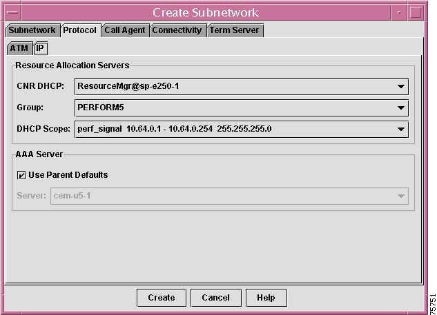
The IP tab is enabled, as shown in Figure 3-4.
Figure 3-4 Create Subnetwork - IP Window
Step 2
Cisco Network Registrar provides a DHCP service and DNS. CNR clients can use CNR to obtain their IP address assignments and other configuration information through the DHCP service while DNS is used to resolve the IP addresses to a hostname. The Network Inventory Manager retrieves this information from the /CSCOcnscs/resourceMgr/common/resourceMgr.cfg file.
Step 3
The group name collectively identifies the IP addresses (IP address pools) within this subnetwork that are to be allocated for voice signaling and bearer PVCs. For example, MGX1. The Network Inventory Manager retrieves this information from the /CSCOcnscs/resourceMgr/common/ipservice.cfg file.
Step 4
The DHCP scope identifies the name of the IP address pool, IP address range, and subnet mask that are to be used for IP address allocation for voice signaling. The GUI displays the information in the following format:
<scope name> <IPaddress>-<IP address> <subnetmask>
For example:
signal 101.32.104.50-102.32.104.100 255.255.255.0The Network Inventory Manager retrieves this information from the /CSCOcnscs/resourceMgr/common/ipservice.cfg file.
Step 5
•
•
Specifying Call Agent Attributes for a Subnetwork
Step 1
The Call Agent tab is enabled, as shown in Figure 3-5.
Figure 3-5 Create Subnetwork - Call Agent Window

Step 2
A call agent is an external control element that provides call control intelligence for VoIP networks. You can have only one call agent configured for your system. The call agent attributes can only be set from the root subnetwork. In all other subnetworks, call agent information is read-only.
The information is as follows:
•
•
–
–
•
–
–
•
Step 3
Clicking Create saves attributes at all of the tabs and closes the window. Only the fields in the Subnetwork Attributes tab are required to create a subnetwork. If you wish to fill in values for other tabs, wait to click Create until you have filled them all in.
To specify other attributes for the subnetwork, see the following sections:
•
•
Step 4
Specifying Connectivity Attributes for a Subnetwork
The connectivity attributes are used when you are using the Telnet or Console mode to download. If you are using the Console mode to download, the applicable attributes are as follows:
•
•
All other connectivity attributes apply when using Telnet mode to download.
This is the second tab when creating a subnetwork.
Before You Begin
Step 1
Step 2
The Create Subnetwork window appears with the Subnetwork Attributes tab enabled.
Follow the instructions described in the "Creating a Subnetwork" section.
Procedure
Step 1
The Connectivity Attributes tab is enabled, as shown in Figure 3-6.
Figure 3-6 Create Subnetwork - Connectivity Attributes Window
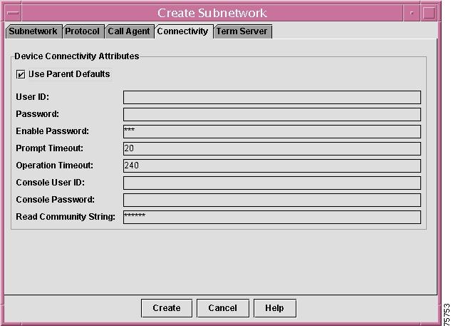
The Network Inventory Manager automatically retrieves the Connectivity attributes defined for the parent of the network object you are creating when the Use Parent Defaults checkbox is enabled. It is enabled by default. If you do not want to use the parent values, be sure the check box is disabled.
Step 2
Step 3
Step 4
The enable password depends upon the privilege level set at the router.
Step 5
The number of seconds that can elapse before a response to a router prompt is required. If this timeout expires, an error message is generated. The default is 20 seconds. This value is retrieved from the cnscs.properties.initial file, but you can change it at this window. If you have checked the Use Parent Defaults checkbox, the Network Inventory Manager retrieves this value from the object's parent.
Step 6
The number of seconds that a router runtime operation has to complete. If this timeout expires, an error message is generated. The default is 240 seconds. This value is retrieved from the cnscs.properties.initial file, but you can change it at this window. If you have checked the Use Parent Defaults checkbox, the Network Inventory Manager retrieves this value from the object's parent.
Step 7
Step 8
Step 9
Step 10
Clicking Create saves attributes at all of the tabs and closes the window. Only the fields in the Subnetwork Attributes tab are required to create a subnetwork. If you wish to fill in values for other tabs, wait to click Create until you have filled them all in.
To specify other attributes for your subnetwork, see the following sections:
•
Step 11
Specifying Terminal Server Attributes for a Subnetwork
The terminal server attributes define information used only when using the Console mode to download.This is the third tab when creating a subnetwork.
Before You Begin
Step 1
Step 2
The Create Subnetwork window appears with the Subnetwork Attributes tab enabled.
Follow the instructions described in the "Creating a Subnetwork" section.
Procedure
Step 1
The Term Server tab is enabled, as shown in Figure 3-7.
Figure 3-7 Create Subnetwork - Term Server Attributes Window
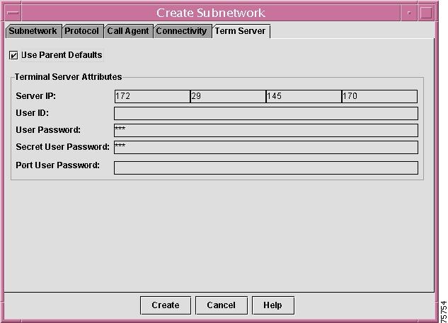
If the Use Parent Defaults checkbox is enabled, the Network Inventory Manager automatically retrieves the Terminal Server attributes defined for the parent of the network object you are creating. It is enabled by default. If you do not want to use the parent values, be sure the check box is disabled.
Step 2
Step 3
Step 4
Step 5
This is the encrypted enable password on the router. If the encrypted password is not used on the router, this is the enable password.
Step 6
CCNSC SP does not support port username configuration directly.
Step 7
Clicking Create saves attributes at all the tabs and closes the window. Only the fields in the Subnetwork Attributes tab are required to create a subnetwork. If you wish to fill in values for other tabs, wait to click Create until you have filled them all in.
To specify other attributes for your subnetwork, see the following sections:
•
Step 8
Creating a Complex
When you create a complex, you are arbitrarily segmenting your network to provide a multilevel, hierarchical routing structure while shielding the complex from the addressing complexity of attached networks. You can create a complex to be directly subordinate to the Root node or a subnetwork.
Procedure
Step 1
Step 2
The Create Complex window appears, with the IP Aggregator Complex tab enabled, as shown in Figure 3-8.
Figure 3-8 Create Complex - IP Aggregator Complex Window
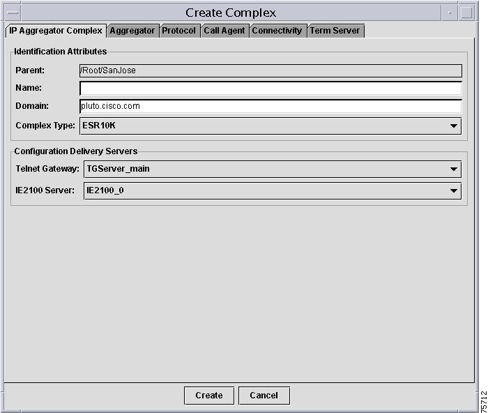
Step 3
You can select the following complex types:
•
•
The Network Inventory Manager automatically retrieves and selects the configured values of the Parent, Configuration Delivery Servers, Call Agent, and Resource Allocation Servers from various configuration files. If more than one value is configured for a particular field, you can select from a drop-down list. The Parent and Call Agent information always have only one value, therefore you will not need to select a value for these fields.
If you selected an MGX complex, the FR Aggregator Complex tab appears.
If you selected an ESR10K complex type, the IP Aggregator Complex tab appears.
Step 4
The parent for the network object you are creating is automatically provided for you based on the Root node or subnetwork under which you are creating this network object. This identifies the Network Inventory Manager Root as it is defined in the ACT server. The top level parent is always /Root. You cannot select a different value.
Step 5
Step 6
A domain is a portion of the naming hierarchy tree that refers to general groupings of networks based on organization-type or geography. This domain name must be configured to match the one defined in DNS.
Step 7
The Configuration Delivery Manager will send the configuration for downloading onto the device using this Telnet Gateway. The Network Inventory Manager retrieves this information from the cdm.properties file in the /opt/CSCOcnscs/cdm directory. The Telnet Gateway method can be used for downloading configurations to devices. If you select this method, you must also define terminal server attributes and connectivity attributes.
Step 8
You are now ready to specify aggregator attributes.
Specifying Aggregator Attributes
Step 1
The Aggregator tab is enabled.
Step 2
This name must be unique among all inventoried aggregators. If you specify a name that is not unique, an error message is returned.
Step 3
Step 4
Step 5
Clicking Create saves attributes for all tabs and closes the window.
Step 6
Specifying Protocol Attributes for a Complex
Step 1
The Protocol tab is enabled. There are two subtabs in this window—the ATM tab and the IP tab. If the complex type is ESR10K, only the IP tab is enabled. If the complex type is MGX, only the ATM tab is enabled.
Step 2
See the following sections for specific information:
•
•
Step 3
Clicking Create saves attributes in all of the tabs and closes the window. Only the fields in the Subnetwork Attributes tab are required to create a subnetwork. If you wish to fill in values for other tabs, wait to click Create until you have filled them all in.
To specify other attributes for the subnetwork, see the following sections:
•
•
Step 4
Specifying ATM Attributes for a Complex
Step 1
The ATM tab is enabled, as shown in Figure 3-9.
Figure 3-9 Create Subnetwork - ATM Window
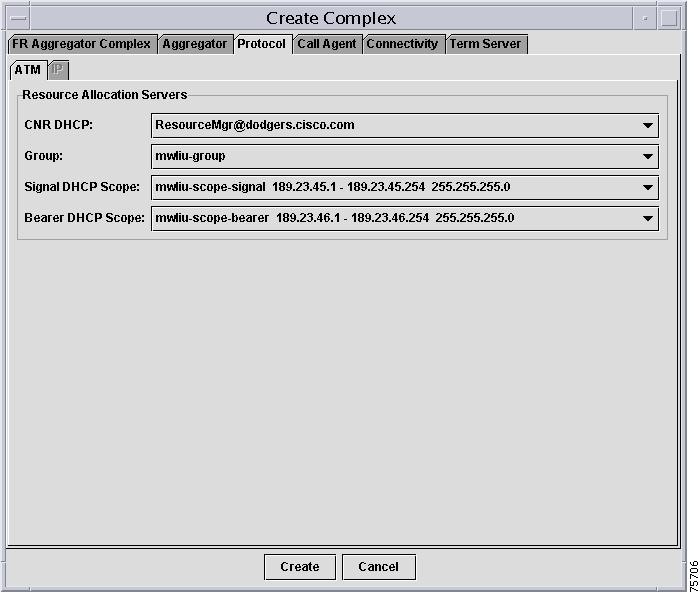
Step 2
The Cisco Network Registrar provides a DHCP service and DNS. CNR clients can use CNR to obtain their IP address assignments and other configuration information through the DHCP service while DNS is used to resolve the IP addresses to a hostname. The Network Inventory Manager retrieves this information from the /CSCOcnscs/resourceMgr/common/ResourceMgr.cfg file.
Step 3
The group name collectively identifies the IP addresses (IP address pools) within this subnetwork that are to be allocated for voice signaling and bearer PVCs. For example, MGX1. The Network Inventory Manager retrieves this information from the /CSCOcnscs/resourceMgr/common/ipservice.cfg file.
Step 4
The Signal and Bearer DHCP scopes that you select must be in the same group.The Signal DHCP scope identifies the name of the IP address pool, IP address range, and subnet mask that are to be used for IP address allocation for voice signaling. The GUI displays the information in the following format:
<scope name> <IPaddress>-<IP address> <subnetmask>
For example:
signal 101.32.104.50-102.32.104.100 255.255.255.0The Network Inventory Manager retrieves this information from the /CSCOcnscs/resourceMgr/common/ipservice.cfg file.
Step 5
The Signaling and Bearer DHCP scopes that you select must be in the same group.The Bearer DHCP scope identifies the name of the IP address pool, IP address range, and subnet mask that are to be used for IP address allocation for voice bearer. The GUI displays the information in the following format:
<scope name> <IPaddress>- <IP address> <subnetmask>
For example:
bearer 101.32.105.50-102.32.105.100 255.255.255.0The Network Inventory Manager retrieves this information from the /CSCOcnscs/resourceMgr/common/ipservice.cfg file.
Specifying IP Attributes for a Complex
Step 1
The IP tab is enabled, as shown in Figure 3-10.
Figure 3-10 Create Subnetwork Window - IP

Step 2
The Cisco Network Registrar provides a DHCP service and DNS. CNR clients can use CNR to obtain their IP address assignments and other configuration information through the DHCP service, and DNS is used to resolve the IP addresses to a hostname. The Network Inventory Manager retrieves this information from the /CSCOcnscs/resourceMgr/common/ResourceMgr.cfg file.
Step 3
The group name collectively identifies the IP addresses (IP address pools) within this subnetwork that are to be allocated for voice signaling and bearer PVCs. For example, MGX1. The Network Inventory Manager retrieves this information from the /CSCOcnscs/resourceMgr/common/ipservice.cfg file.
Step 4
The DHCP scope identifies the name of the IP address pool, IP address range, and subnet mask that are to be used for IP address allocation for voice signaling. The GUI displays the information in the following format:
<scope name> <IPaddress>-<IP address> <subnetmask>
For example:
signal 101.32.104.50-102.32.104.100 255.255.255.0The Network Inventory Manager retrieves this information from the /CSCOcnscs/resourceMgr/common/ipservice.cfg file.
Step 5
•
•
Specifying Call Agent Attributes
Step 1
The Call Agent tab is enabled, as shown in Figure 3-11.
Figure 3-11 Create Subnetwork - Call Agent Window
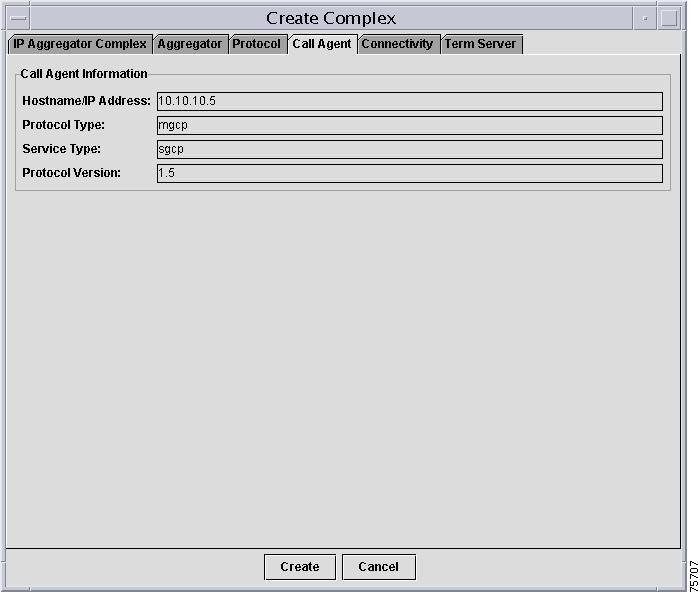
Step 2
A call agent is an external control element that provides call control intelligence for VoIP networks. You can have only one call agent configured for your system. The call agent attributes can only be set from the root subnetwork. In all other subnetworks, call agent information is read-only.
The information is as follows:
•
•
–
–
•
–
–
•
Step 3
Clicking Create saves attributes at all of the tabs and closes the window. Only the fields in the Subnetwork Attributes tab are required to create a subnetwork. If you wish to fill in values for other tabs, wait to click Create until you have filled them all in.
To specify other attributes for the subnetwork, see the following sections:
•
•
Step 4
Specifying Connectivity Attributes for a Complex
The connectivity attributes are used when you are using the Telnet or Console mode to download. If you are using the Console mode to download, the applicable attributes are as follows:
•
•
All other connectivity attributes apply when using Telnet mode to download.
This is the second tab when creating a subnetwork.
Before You Begin
Step 1
Step 2
The Create Complex window appears with the Subnetwork Attributes tab enabled.
Follow the instructions described in the "Creating a Subnetwork" section.
Procedure
Step 1
The Device Connectivity Attributes tab is enabled, as shown in Figure 3-12.
Figure 3-12 Create Subnetwork - Connectivity Attributes Window
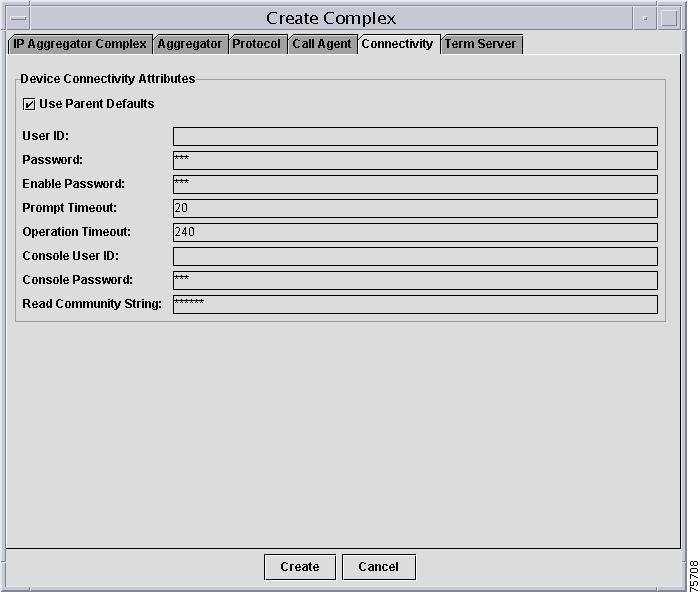
The Network Inventory Manager automatically retrieves the Connectivity attributes defined for the parent of the network object you are creating when the Use Parent Defaults checkbox is enabled. It is enabled by default. If you do not want to use the parent values, be sure the check box is disabled.
Step 2
Step 3
Step 4
The enable password depends upon the privilege level set at the router.
Step 5
The number of seconds that can elapse before a response to a router prompt is required. If this timeout expires, an error message is generated. The default is 20 seconds. This value is retrieved from the cnscs.properties file, but you can change it at this window. If you have checked the Use Parent Defaults checkbox, the Network Inventory Manager retrieves this value from the object's parent.
Step 6
The number of seconds that a router runtime operation has to complete. If this timeout expires, an error message is generated. The default is 240 seconds. This value is retrieved from the cnscs.properties file, but you can change it at this window. If you have checked the Use Parent Defaults checkbox, the Network Inventory Manager retrieves this value from the object's parent.
Step 7
Step 8
Step 9
Step 10
Clicking Create saves attributes at all of the tabs and closes the window. Only the fields in the Subnetwork Attributes tab are required to create a subnetwork. If you wish to fill in values for other tabs, wait to click Create until you have filled them all in.
To specify other attributes for your subnetwork, see the following sections:
•
Step 11
Specifying Terminal Server Attributes for a Complex
The terminal server attributes define information used only when using the Console mode to download.This is the third tab when creating a complex.
Before You Begin
Step 1
Step 2
The Create Complex window appears with the IP Aggregator Attributes tab enabled.
Follow the instructions described in the "Creating a Subnetwork" section.
Procedure
Step 1
The Term Server Attributes tab becomes enabled, as shown in Figure 3-13.
Figure 3-13 Create Subnetwork - Term Server Attributes Window
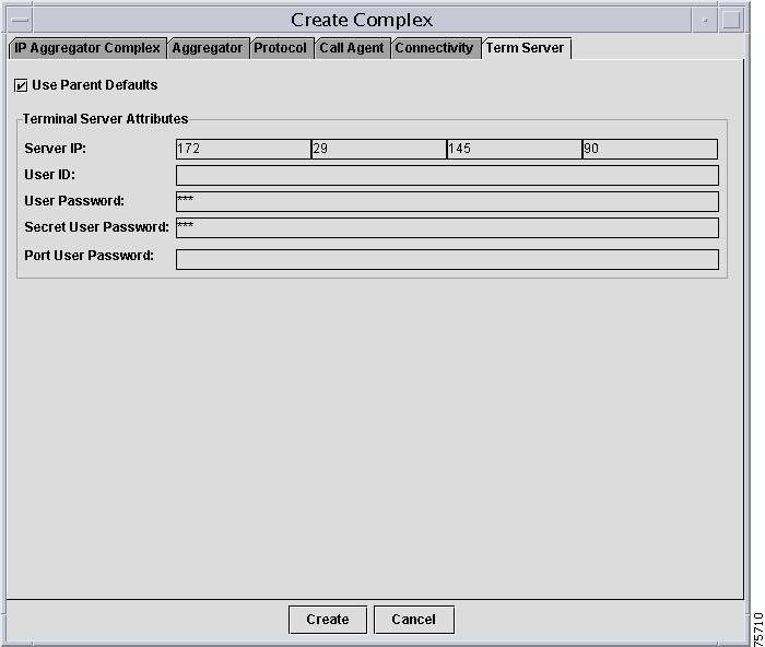
If the Use Parent Defaults checkbox is enabled, the Network Inventory Manager automatically retrieves the Terminal Server attributes defined for the parent of the network object you are creating. It is enabled by default. If you do not want to use the parent values, be sure the check box is disabled.
Step 2
Step 3
Step 4
Step 5
This is the encrypted enable password on the router. If the encrypted password is not used on the router, this is the enable password.
Step 6
CCNSC SP does not support port username configuration directly.
Step 7
Clicking Create saves attributes at all the tabs and closes the window. Only the fields in the Subnetwork Attributes tab are required to create a subnetwork. If you wish to fill in values for other tabs, wait to click Create until you have filled them all in.
To specify other attributes for your subnetwork, see the following sections:
•
Step 8
Viewing and Modifying Subnetwork or Complex Properties
You can view and modify the currently configured properties of a subnetwork or a complex. The Network Inventory Manager automatically retrieves the configured subnetwork, connectivity, and terminal server attributes.
The interface for viewing and modifying subnetwork properties is identical to the interface for creating subnetworks, except that the Name field is not editable and the Aggregator tab is not included.
For information on Aggregator properties see the "Specifying Protocol Attributes for a Subnetwork" section.
Viewing and Modifying Aggregator Properties
You can view and modify the currently configured properties of an aggregator associated with a Aggregator Complex. The Network Inventory Manager automatically retrieves the configured aggregator attributes.
Procedure
Step 1
Step 2
The Aggregator Properties window appears, as shown in Figure 3-14, with the Aggregator Attributes tab enabled. The window for both ESR10K and MGX aggregators is similar, however, in the window for the MGX, the IP address is optional.
Figure 3-14 Aggregator Properties - Aggregator Window

If you want to change the connectivity attributes for this aggregator, click the Connectivity tab. The Aggregator Properties window now displays the connectivity properties, as shown in Figure 3-15.
Figure 3-15 Aggregator Properties - Connectivity Window

Once you have created an aggregator, you can modify its attributes. For detailed information about these attributes, see the "Specifying Protocol Attributes for a Subnetwork" section and the "Specifying Connectivity Attributes for a Subnetwork" section.
Step 3
You are returned to the Tree View.
Working with Devices
CCNSC Subscriber Provisioning supports T1 CPEs used with Voice over IP over T1 solutions and, in addition, supports provisioning of the following devices:
•
•
•
You can create devices at the Network Inventory Manager windows to be managed by CCNSC Subscriber Provisioning (new CPEs), or you can select existing provisioned devices to be managed by CCNSC Subscriber Provisioning (CPEs deployed only in an ESR10K complex). The actions available for the devices depend upon the device type. The following sections indicate the specific actions available for a device type:
•
•
When configuring devices, it may be useful to understand the states and state transitions for the devices. Seethe "Device States and Transitions" section for more information.
Device States and Transitions
CCNSC Subscriber Provisioning supports several states for an ESR10K complex or an MGX complex. In addition, CCNSC Subscriber Provisioning defines the states a device can transition to and from.
Devices in an ESR10K complex can be in only one of the following states at any given time:
•
•
•
Figure 3-16 shows the state transitions for devices in an ESR10K complex.
Figure 3-16 State Transitions for Devices in an ESR10K Complex

If you are provisioning the device using a Cisco IE2100, there is one additional state, as shown in Figure 3-17.
•
Figure 3-17 State Transitions for Devices in an ESR10K Complex (with Cisco IE2100 Provisioning)

The devices in an MGX complex can have two additional states:
•
•
Figure 3-18 shows a state diagram for devices in an MGX complex.
Figure 3-18 State Transitions for Devices in an MGX Complex
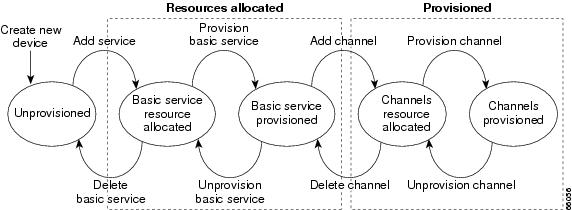
Table 3-2 lists and describes the state transitions supported in CCNSC Subscriber Provisioning.
Working with New Devices
A new device is a T1 CPE for an MGX complex (a Cisco 3660, Cisco 2421, or Cisco 3810 CPE device), a T1 device for and ESR10K complex, or a new device for a subnetwork (a 911 Gateway, ESR10K, or Cisco 7200) that you are creating in the Network Inventory Manager. You can provision T1 CPEs. The 911 gateway provides gateway service to 911 servers, which are designed to handle emergency 911 calls. You must use the Telnet Gateway download method for 911 gateways, Cisco 7200s, and ESR10K routers.
Note
The actions available for New CPE devices are as follows:
•
•
•
•
•
•
•
•
•
•
Creating New Devices
Before You Begin
•
•
Procedure
Step 1
Step 2
•
•
The Create New Device window appears.
Figure 3-19 shows the Create New Device window for T1 CPE devices.
Figure 3-19 Create New Device Dialog Box for a T1 CPE Device

Figure 3-20 shows the Create New Device window for 911 Gateway, ESR10K, and Cisco 7200 devices.
Figure 3-20 Create New Device Dialog Box for 911 Gateway, ESR10K, or Cisco 7200

Step 3
The types listed in the drop-down list depend upon whether you are creating the device under a subnetwork or a Aggregator Complex. You can create the following device types:
•
•
•
•
Step 4
This name uniquely identifies the device throughout its subnetwork. If a device with this name already exists, an error is returned and an entry is created in the log file.
Step 5
This is an arbitrary number that provides a unique ID to a subscriber. It does not apply to 3660s. This ID can be used to track log information in the Log Viewer. This field is optional. For information about using the Log Viewer, see "Using the Log Viewer."
Step 6
The location helps you to identify the physical site of the 3660 device, for example, San Jose-Bldg 3. This is informational only and has no effect on the operation of the device.
Step 7
When you create a CPE device, it appears in the Tree View and is followed with (Unprovisioned) to indicate that this device has not been provisioned or had resources allocated for it.
For more information about device states and transitions between them, see "Device States and Transitions" section.
Note
Proceed to "Adding a Service to a New CPE" to continue provisioning the new T1 CPE.
Adding a Service to a New CPE
When you add a service to a new CPE, you identify the service that you want for this particular device and you allocate IP addresses from the specified scope (IP address pool). The possible voice and data selections are:
•
•
•
The interface for adding a service varies depending upon which type of device you are adding and whether you are adding it to an MGX complex or an ESR10K complex. You can add services for the following devices in the following contexts:
•
•
•
The following sections describe adding services for particular devices.
Adding a Service to a 3660 in an MGX Complex
Before You Begin
•
•
Adding a Basic Service for a 3660 CPE Device
Step 1
Step 2
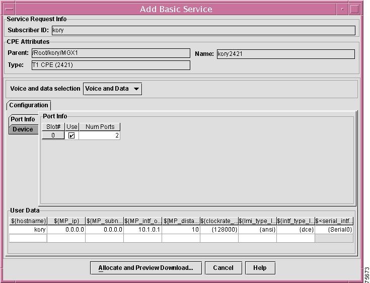
An Add Service window appears, with the Port Info tab enabled, as shown in Figure 3-21.
Figure 3-21 Add Basic Service - Port Info Window

The Service Request Info that displays at this window corresponds with the information you specified at the Create New Device window. For more information about these fields, see the "Creating New Devices" section.
Step 3
T1 CPEs support the following voice and data selections:
•
•
•
Note
Step 4
a.
b.
c.
Step 5
The Device tab is enabled, as shown in Figure 3-22.
Figure 3-22 Add Basic Service - Devices Window

For each slot that you have enabled, specify the following information:
•
•
•
Step 6
The Configuration File Generation window appears. This window shows router configuration commands that have been generated based upon the configuration options you selected.
Step 7
Step 8
•
•
•
If the IP address you specified is incorrect or unreachable, an error message appears.
If you cancel the configuration, the device is marked as ResourceAllocated in the Tree View.
The device is now in the Provisioned state.
Adding a Channel for a 3660 CPE Device
Once you have added basic service for the 3660 device, you can provision voice and data channels.
Step 1
Step 2
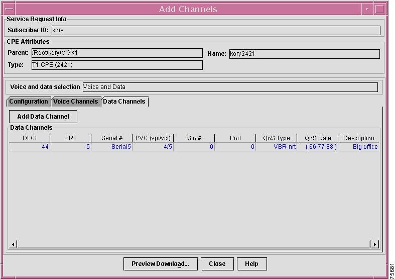
The Add Channels window appears, as shown in Figure 3-23.
Figure 3-23 Add Channels Window
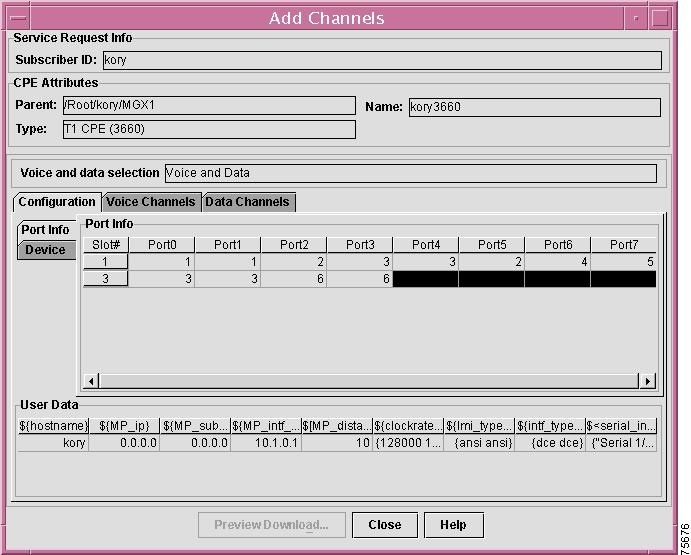
Step 3
The Add Channels window for voice channels appears, as shown in Figure 3-24.
Figure 3-24 Add Channels - Voice Channels Window
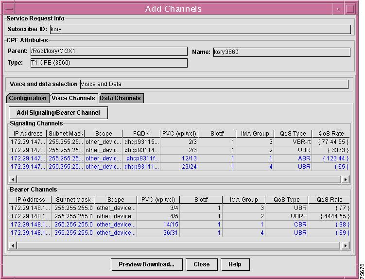
Channels for which resources have been allocated but which have not been provisioned are highlighted in blue. Provisioned channels appear in black.
Step 4
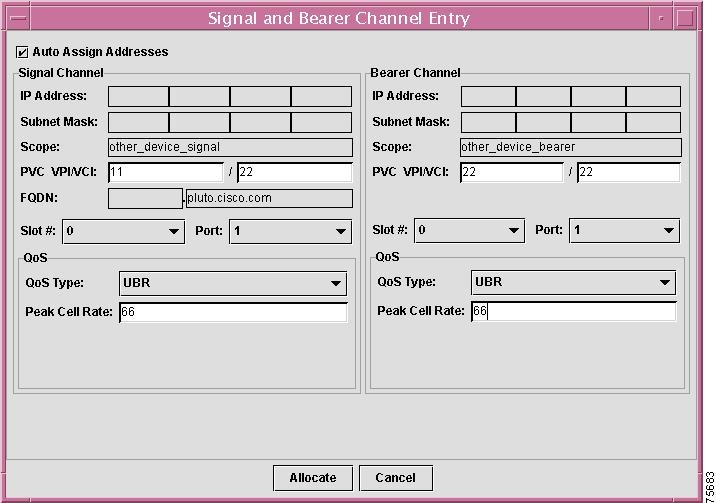
The Signal and Bearer Channel Entry window appears, as shown in Figure 3-25.
Figure 3-25 Signal and Bearer Channel Entry Window

If you are using Cisco Network Registrar, then CNR will update the signalling IP address to the value assigned by CNR's Domain Name Service (DNS) server. Make sure that the IP address is set up properly to allow DNS update in the CNR server.
The back end processor will only use the information that you specify in the Signal Channel area of the window; however, you must still specify information in the fields in the Bearer Channel area of the window.
Complete these steps to specify signal channel information:
a.
b.
–
–
–
c.
d.
You can select the following QoS types:
–
–
–
–
–
–
e.
You can select the following QoS types:
–
–
–
–
–
–
f.
–
–
–
Step 5
a.
The Data Channels tab is enabled, as shown in Figure 3-26.
Figure 3-26 Add Channels - Data Channels Window
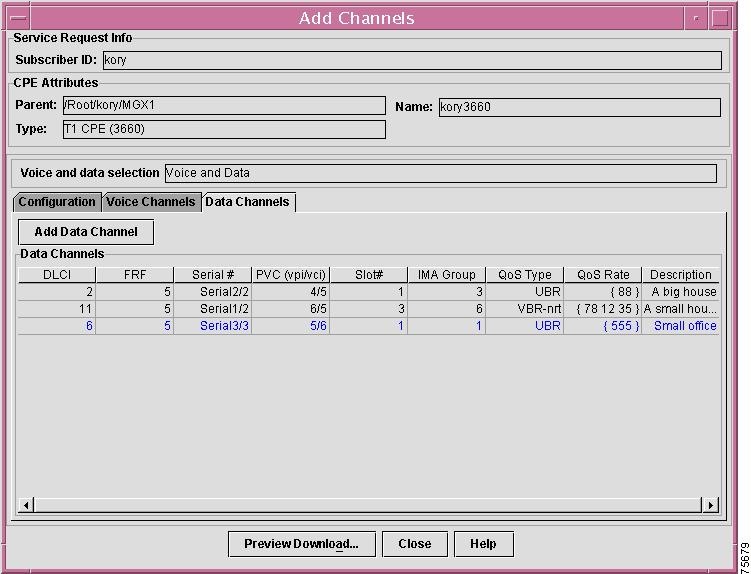
Data channels that are already provisioned are highlighted in blue. Unprovisioned data channels appear in black.
b.
The Data Channel Entry window appears, as shown in Figure 3-27.
Figure 3-27 Data Channel Entry Window

c.
–
–
–
–
–
UBR
UBR+
VBR-rt
VBR-nrt
CBR
ABR
–
–
d.
The channel is allocated.
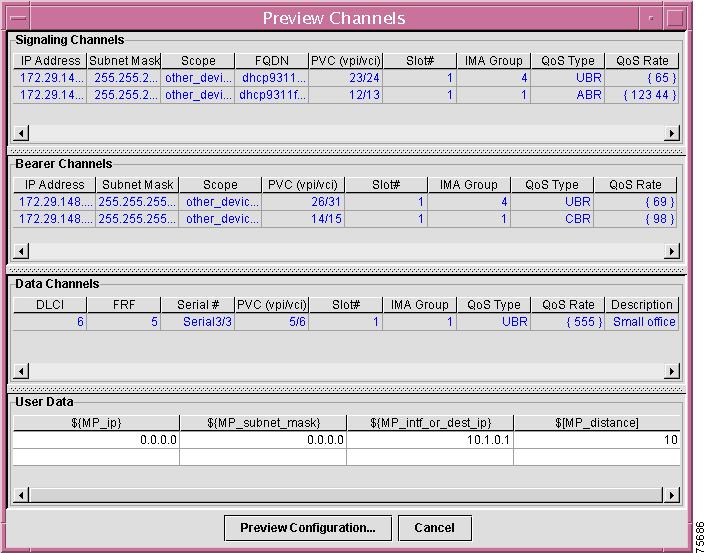
Step 6
The Preview Channels window appears, as shown in Figure 3-28.
Figure 3-28 Preview Channels Window
Step 7
Step 8
•
•
If you select Preview Configuration, the Configuration File Generation window appears, as shown in Figure 3-29. This window shows router commands that have been generated as a result of your selections.
Figure 3-29 Configuration File Generation Window

Step 9
Step 10
•
•
a.
–
–
–
b.
•
•
c.
Initial configuration for the 3660 device is complete. You can now add multiple voice channels or multiple data channels.
Adding a Service to a Cisco 2421 or a Cisco 3810 in an MGX Complex
Before You Begin
•
•
Adding a Basic Service for a 2421 or a 3810 CPE Device
Step 1
Step 2
Figure 3-30 Add Basic Service - Port Info Window
The Service Request Info that displays at this window corresponds with the information you specified at the Create New Device window. For more information about these fields, see the "Creating New Devices" section.
Step 3
T1 CPEs support the following voice and data selections:
•
•
•
Note
Step 4
d.
e.
Step 5
The Device tab is enabled, as shown in Figure 3-31.
Figure 3-31 Add Basic Service - Devices Window

For each port that you have enabled, specify the following information:
•
•
•
Step 6
The Configuration File Generation window appears. This window shows router configuration commands that have been generated based upon the configuration options you selected.
Step 7
Step 8
•
•
•
If the IP address you specified is incorrect or unreachable, an error message appears.
If you cancel the configuration, the device is marked as ResourceAllocated in the Tree View.
If you clicked the Download button, the device is now in the Provisioned state.
You are now ready to add Voice and/or Data channels for the device.
Adding a Channel for a 2421 or a 3810 CPE Device
Once you have added basic service for the 2421 or 3810 device, you can provision voice and data channels.
Step 1
Step 2
The Add Channels window appears, as shown in Figure 3-32.
Figure 3-32 Add Channels Window

Step 3
The Add Channels window for voice channels appears, as shown in Figure 3-33.
Figure 3-33 Add Channels - Voice Window
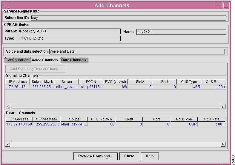
Channels for which resources have been allocated but have not been provisioned are highlighted in blue. Provisioned channels appear in black.
Step 4
Note
The Signal and Bearer Channel Entry window appears, as shown in Figure 3-34.
Figure 3-34 Signal and Bearer Channel Entry Window
The back end processor will only use the information that you specify in the Signal Channel area of the window; however, you must still specify information in the fields in the Bearer Channel area of the window.
Complete these steps to specify signal channel information:
a.
b.
–
–
–
Note
c.
d.
You can select the following QoS types:
–
–
–
–
–
–
e.
f.
–
–
g.
h.
You can select the following QoS types:
–
–
–
–
–
–
i.
–
Step 5
a.
The Data Channels tab is enabled, as shown in Figure 3-35.
Figure 3-35 Add Channels - Data Channels Window
Data channels that are already provisioned are highlighted in blue. Unprovisioned data channels appear in black.
b.
The Data Channel Entry window appears, as shown in Figure 3-36.
Figure 3-36 Data Channel Entry Window

c.
–
–
–
–
–
UBR
UBR+
VBR-rt
VBR-nrt
CBR
ABR
–
–
–
d.
The channel is allocated.
Step 6
The Preview Channels window appears, as shown in Figure 3-37.
Figure 3-37 Preview Channels Window
Step 7
•
•
If you select Preview Configuration, the Configuration File Generation window appears, as shown in Figure 3-38. This window shows router commands that have been generated as a result of your selections.
Figure 3-38 Configuration File Generation Window
Step 8
Step 9
a.
–
–
–
b.
•
•
c.
Step 10
•
•
Configuration for the 3810 or 2421device is complete. If you clicked Download, the device is now marked as Provisioned in the Tree View.
Adding a Service to a 2421 in an ESR10K Complex
Once you have created an ESR10K complex and have added devices to it, you can add services to the complex.
Before You Begin
•
•
Adding a Basic Service for a 2421 CPE Device in an ESR10K Complex
Step 1
Step 2
The Allocate Resources window appears, with the Management tab enabled, as shown in Figure 3-39.
Figure 3-39 Allocate Resources - Management Window

The Service Request Info that displays at this window corresponds with the information you specified at the Create New Device window. For more information about these fields, see the "Creating New Devices" section.
Step 3
T1 CPEs support the following voice and data selections:
•
•
•
Note
Step 4
Step 5
•
•
•
Step 6
The Data Services tab is enabled, as shown in Figure 3-40.
Figure 3-40 Allocate Resources - Data Services Window

Step 7
•
•
Step 8
The DHCP tab is enabled, as shown in Figure 3-41.
Figure 3-41 Allocate Resources - DHCP Window
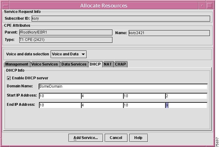
Step 9
•
•
Step 10
•
•
•
Step 11
The NAT tab is enabled, as shown in Figure 3-42.
Figure 3-42 Allocate Resources - NAT Window

Step 12
You can use NAT to enable users to access Internet services when there is an insufficient number of IP addresses for all users who need access.
If you leave the Enable NAT checkbox unchecked, the entry fields in the NAT tab are disabled.
Step 13
•
•
•
Step 14
Step 15
Figure 3-43 Allocate Resources - CHAP Window

Step 16
•
•
If the Do Not use PPP authentication with this CPE checkbox is checked, then the entry fields in the CHAP tab are disabled.
Step 17
a.
b.
–
–
Step 18
The Allocate Resources window appears. The entry fields are greyed out, as shown in Figure 3-44.
Figure 3-44 Allocate Resources Window

Step 19
•
•
If you click Done, the device is marked with the indication ResourceAllocated.
If you click Provision, the New Provision window appears, as shown in Figure 3-45.
Figure 3-45 New Provision Window
Step 20
Step 21
The Configuration File Generation window appears, as shown in Figure 3-46.
Figure 3-46 Configuration File Generation Window
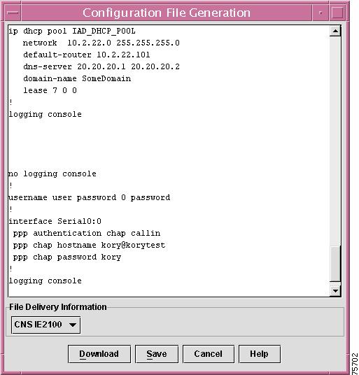
The Configuration File Generation window shows router configuration commands that have been generated based upon your selections in the Allocate Resources window.
Step 22
Step 23
•
•
•
a.
–
–
–
–
b.
The device is now marked as Provisioned in the Tree View.
Provisioning a New CPE Device for an ESR10K Complex
You can provision a new CPE device (Cisco 2421 CPE) under and ESR10K complex in two ways:
1.
2.
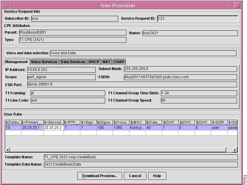
The information you provide at this window will be provided as input to the appropriate template. Based upon the service type you have selected, CCNSC Subscriber Provisioning provisions voice or data services. Once CCNSC Subscriber Provisioning updates the template, it generates a configuration file. It then stores this configuration file in the CCNSC Subscriber Provisioning Repository, specifically the Oracle database, until it is downloaded onto the device. For information about the templates supported in CCNSC Subscriber Provisioning, see Chapter 4, "Using the Template Manager."
Before You Begin
•
–
–
–
Procedure
Step 1
The New Provision window appears, as shown in Figure 3-47.
Figure 3-47 New Provision Window
Step 2
The Configuration File Generation window appears, as shown in Figure 3-48.
Figure 3-48 Configuration File Generation Window
The Configuration File Generation window shows router configuration commands that have been generated based upon your selections in the Allocate Resources window.
Step 3
Step 4
•
•
•
a.
–
–
–
–
b.
The device is now marked as Provisioned in the Tree View.
Refreshing the Tree View
Refreshing the Tree View updates the Device Tree with any changes that have been made since the last refresh.
Procedure
Step 1
Step 2
The Tree View is updated with any changes you have made.
Refreshing the Server Configuration
Refreshing the server configuration updates the information in the CCNSC Subscriber Provisioning Repository with changes you have made to the ResourceMgr.cfg file. These changes are reflected at the appropriate windows throughout the Network Inventory Manager.
You should refresh the server configuration when you make changes to the ResourceMgr.cfg or /CSCOcnscs/resourceMgr/common/ipservice.cfg files. If you do not refresh the server after making changes to these files, your changes will not be visible in the GUI.
If you change the CNR server, FTP server, or Telnet Gateway in the ResourceMgr.cfg file for a subnetwork or Aggregator complex, the values for these servers in Properties window for the subnetwork or Aggregator complex are empty after you refresh the server configuration.
Note
Procedure
Step 1
Step 2
The CCNSC Subscriber Provisioning Repository is updated and so are the Network Inventory Manager windows that are affected by the changed information.
Viewing and Modifying Telnet Gateway Properties
You can view and modify the current configured properties of the Telnet Gateway. The Telnet Gateway operates in conjunction with the TFTP server. The Network Inventory Manager automatically retrieves the configured properties.
Note
Procedure
Step 1
Step 2
Step 3
The Telnet Gateway Properties window appears with the Properties tab enabled, as shown in Figure 3-49.
Figure 3-49 Telnet Gateway Properties Window
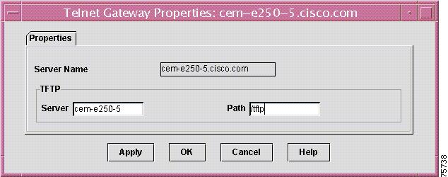
You can view all properties, but you cannot modify all of them. Table 3-3 describes the Telnet Gateway properties.
Step 4
Step 5
You are returned to the Tree View.
Viewing CPE Properties
Procedure
Step 1
Step 2
The CPE Properties window appears, as shown in Figure 3-50. The following figure shows the CPE Properties window for a 2421 device under and ESR10K complex.
Figure 3-50 CPE Properties Window

The properties displayed at this window cannot be modified. See "Creating New Devices" section for information about these fields.
Step 3
The Properties window for the subnetwork appears. For information about these fields, see "Creating a Subnetwork" section.
Step 4
Viewing and Modifying Element Properties
You can view and modify all currently configured element properties for a CPE, 911 gateway. Cisco 7200, or Cisco ESR10K; the properties you can define are the same whether you are working with a T1 CPE another device. The Network Inventory Manager automatically retrieves the configured General and Terminal Server attributes for the parent object making modification of the element properties optional. However, if you want to override the properties of the parent object for a specific device, you can do so at the Element Properties window.
Procedure
Step 1
Step 2
The Element Properties window appears, with the General tab enabled, as shown in Figure 3-51.
Figure 3-51 Element Properties Window

Table 3-4 describes the general properties you can view and modify for an element.
Step 3
Step 4
To view and modify other properties, see the following section:
•
Step 5
You are returned to the Tree View.
Viewing and Modifying Terminal Server Attributes for a CPE
The terminal server attributes define information about the terminal server that will be used to download the configuration to a device. The terminal server attributes define information used only when using Console mode to download.
Procedure
Step 1
Step 2
Step 3
The Terminal Server tab becomes enabled, as shown in Figure 3-52.
Figure 3-52 Element Properties - Terminal Server Window

Table 3-5 describes the Terminal Server properties you can view and modify for an element.
Table 3-5 Terminal Server Properties
Port Number
The port number over which the Terminal Server will communicate with the device. This value is retrieved if the Console download mode is selected to download a configuration to a device as described in "Generating and Downloading a Configuration File to a CPE" section.
Server IP Address
The IP address of the Terminal Server.
Server User ID
The user name for logging into the Terminal Server for purposes of establishing a connection to the device.
Server User Password
The user password for logging into the Terminal Server for purposes of establishing a connection to the device.
Port Password
The password for logging into the Terminal Server port used to access the device. Note that currently Cisco Convergent Network Solution Center: Subscriber Provisioning does not support port usernames.
Step 4
Step 5
To view and modify other properties, see the "Viewing and Modifying Element Properties" section
Step 6
You are returned to the Tree View.
Generating and Downloading a Configuration File to a CPE
The Network Inventory Manager uses the information you provided at the New Provision or Modify Provision window to generate a configuration file and download it onto the device. This task applies to new CPEs and deployed CPEs.
Before You Begin
•
–
–
–
–
Procedure
Step 1
The Configuration File Generation window appears, as shown in Figure 3-53.
Figure 3-53 Configuration File Generation Window
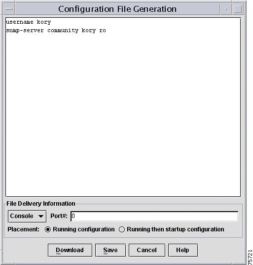
Step 2
See Table 3-6 for a description of the download mode options.
Table 3-6 Download Options
Console
T1 CPE under MGX Complex or ESR10K Complex
Downloads the configuration file using the Console download mode. If you select this file delivery method, you must provide the console port number on the device to which you are downloading the configuration file. This mode is available only for new provisions.
File
T1 CPE under MGX Complex or ESR10K Complex
Saves the configuration file to a file. It can be downloaded at a later time. You can either specify a filename or select one from the browser. If you successfully download using this option, CCNSC Subscriber Provisioning registers the device as provisioned and it appears in the Network Inventory Manager, as provisioned. However, to download the configuration to the device, you will need to download it through the Telnet Gateway download method. For more information about this method, see the "Downloading a Configuration Using a Telnet Gateway" section.
This mode is available only for new provisions.
CNSIE2100
T1 CPE under an ESR10K Complex
Transfers the configuration file, using the Hypertext Transfer Protocol (HTTP), for new and deleted provisioning. Modification of an existing configuration is available only through calls to the Cisco Convergent Network Solution Center: Subscriber Provisioning Application Programming Interface (API) functions.
Telnet
T1 CPE under MGX Complex or ESR10K Complex
Uses the Telnet Gateway server defined in the Subnetwork properties window to copy the configuration file to the path specified in the TG Properties window. This mode can be used for new and deleted provisioning. Modification of existing provisioning can only be done using the Cisco Convergent Network Solution Center: Subscriber Provisioning API functions.
Step 3
This value is retrieved from the Terminal Server Attributes tab of the Element Properties window. If you change the port number at this window, the Element Properties window is not updated with your change. However, if you make a change at the Element Properties window as described in "Viewing and Modifying Terminal Server Attributes for a CPE" section, it will be reflected in this field.
Step 4
The options are as follows:
•
•
Step 5
•
•
•
If you clicked Download, the Download Results window appears, as shown in Figure 3-54.
Figure 3-54 Download Results Window
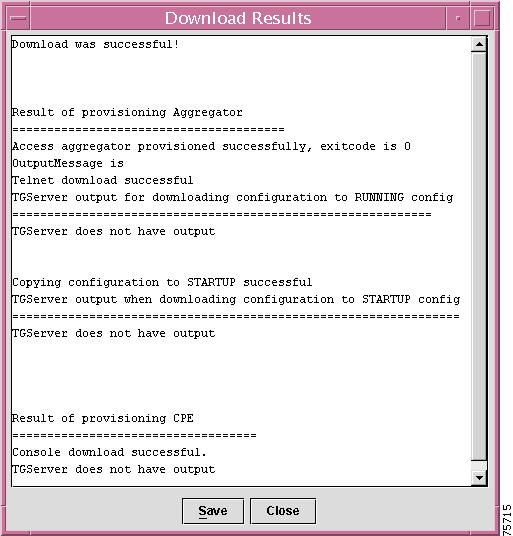
The information displayed includes whether the download was successful or error messages as to why the download failed.
Step 6
Step 7
The device appears as (Provisioned) in the Tree view.
Downloading a Configuration Using a Telnet Gateway
You can use the Telnet Gateway method to download a configuration to any ESR10K, Cisco 7200, or 911 gateway. When you use this download method, the configuration is downloaded over the Console or the Telnet-vty port of the device.
Before You Begin
Provision the device to which you want to download the configuration.
Create a subnetwork as described in the "Creating a Subnetwork" section and then create a new device as described in the "Creating New Devices" section.
Procedure
Step 1
Step 2
The Select Configuration file for download window appears.
Step 3
Step 4
The Download Options window appears.
Step 5
The options are as follows:
•
•
•
•
•
•
Step 6
The Download Status window appears. The information displayed includes whether the download was successful or failed.
Step 7
Step 8
Deleting a Network Object
When you delete a network object, all information about the object is removed from the CCNSC Subscriber Provisioning Repository. You can delete subnetworks, Aggregator Complexes, T1 CPEs (2421s), 3660s, Cisco 7200s, and Cisco ESR10K objects.
Before You Begin
•
•
Procedure
Step 1
Step 2
The Delete Confirmation window appears.
Step 3
Whether you selected Yes or No, you will be returned to the Tree View. However, if you selected Yes, the object no longer appears in the Tree View.
Deleting Provisioning of CPE Device
When you delete the provisioning information for the device, a delete configuration file is downloaded to the device. You can delete provisioning for T1 CPEs (2421s).
Procedure
Step 1
Step 2
The CPE Provision window appears.
Step 3
Provide a service request ID to identify this particular request. You can use it to search the Log Viewer log.
The system automatically selects the appropriate template based upon which service has been provisioned.
Step 4
•
•
If the delete template it successfully downloaded, the state of the device changes to ResourceAllocated and appears following the device in the Tree View.
Deleting a Service for a CPE Device
Procedure
Step 1
Step 2
The Delete Confirmation window appears.
Step 3
Whether you selected Yes or No, you will be returned to the Tree View. However, if you selected Yes, the CPE state changes to Unprovisioned and appears following the device in the Tree View.
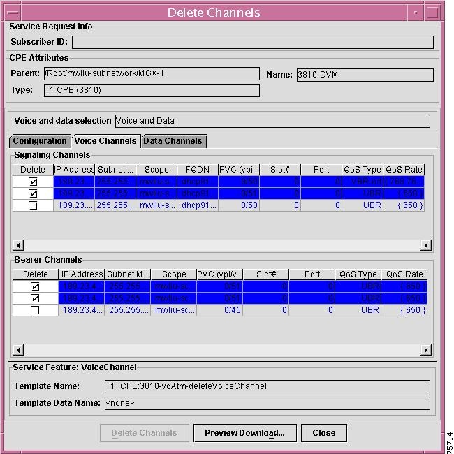
Deleting a Channel for a CPE Device
You can delete channels for a device to which you have added channels. For 3660, 3810, or 2421 devices, choose VoIPoATM devices.
Complete these steps to delete channels:
Step 1
Step 2
Step 3
The Delete Channels window for voice channels appears, as shown in Figure 3-55.
Figure 3-55 Delete Channels - Voice Window
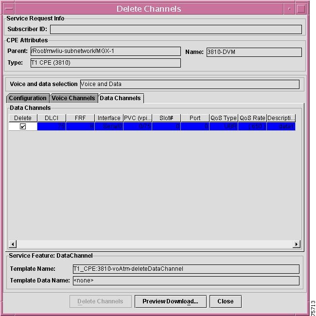
Step 4
The Delete Channels window for data channels appears, as shown in Figure 3-56.
Figure 3-56 Delete Channels - Data Window
Step 5
Step 6
The Preview Channels window appears, as shown in Figure 3-57.
Figure 3-57 Preview Channels Window

Step 7
•
•
The Configuration File Generation window appears, as shown in Figure 3-58.
Figure 3-58 Configuration File Generation Window

Step 8
Step 9
•
•
a.
–
–
–
b.
•
•
If you click Download, the channel configuration is updated.
Setting Debug Levels
You can independently set debug levels for the CCNSC Subscriber Provisioning Client and the CCNSC Subscriber Provisioning Server.
The debug level determines how much debug information will be displayed in the log. Each log level includes the previous level. For example, if you select the Error log level, which is the default, the log will include all Error level and Emergency level messages.
The log level is set in the Nimtree.properties file for the client and the cnscs.properties file for the server. However, you can update the log level value in these files from the GUI.
CCNSC Subscriber Provisioning provides a logEmerg.log file. This log is used to capture Emergency level errors that occur before the other processes used to log information in an audit trail or debugging log can be initialized. For example, the Behavior Manager will write to the logEmerg.log file at startup time when either of the following occur:
•
As a result, any Emergency level errors logged in the logEmerg.log file before the other processes come up, will not appear in an audit trail or in the debugging log.
Procedure
Step 1
The Debug Level Settings window appears, as shown in Figure 3-59.
Figure 3-59 Debug Level Settings Window

Step 2
The possible log levels are described in Table 3-7.
Step 3
After the Tree View is refreshed, "debug" changes back to the default, which is "error," unless changes are made in the Nimtree.properties file for the client or the cnscs.properties file for the server.
Setting Up the Automatic Configuration Feature
If you use CCNSC SP in conjunction with the Cisco Intelligence Engine 2100 (Cisco IE2100), you can then set up CCNSC SP to use the Cisco IE2100 to provision the IAD2421devices that it manages.
In order to use the Cisco IE2100 to provision devices managed by CCNSC SP, you must complete these steps:
1.
2.
3.
4.
Configuring Routers to Communicate with the Cisco IE2100
Complete these steps to configure each IAD2421 that will use the Cisco IE2100 and CCNSC SP to obtain a configuration file.
Step 1
Step 2
cns config initial <Cisco IE2100 ipaddress or DNS name> eventcns id serial <serial interface #> ipaddresscns event <Cisco IE2100 ip or DNS name> keepalive <timeout> <retry>The following example shows the use of these commands:
ip name server 172.29.145.233cns config init RM1.pluto.cisco.com eventcns id serial 0:0 ipaddresscns event RM1.pluto.cisco.com keepalive 5 5
Note
Ensuring That the Complex Properties Page Has the Correct Cisco IE2100 Name
Complete these steps to ensure that the Complex Properties page has the correct Cisco IE2100 name.
Step 1
For specific instructions, refer to the "Creating a Complex" section.
Step 2
For specific instructions, refer to the "Adding a Service to a 2421 in an ESR10K Complex" section.
Establishing the Connection Between the IAD2421 and the Cisco IE2100
Complete these steps to establish a connection between the IAD2421 and the Cisco IE2100.
Step 1
The IAD2421 should read in the CNS agent configuration and use HTTP to get a configuration file from the Cisco IE2100.
Once the IAD2421 finishes downloading the configuration, it remove the cns config init x.x.x.x event command from its startup config file and sends out an event.
Step 2
The CCNSC SP server receives the event and changes the IAD2421's object state from PendingProvisioned to Provisioned. You need to manually refresh the NIM tree to see this.
The Cisco Convergent Network Solution Center: Subscriber Provisioning CDM server appends the cns config partial x.x.x.x command to the end of the generated configuration file. Once the configuration download is complete, the IAD2421 should have the following three CNS command lines:
cns config partial <Cisco IE2100 IP address or DNS name>cns id serial <port#> ipaddresscns event <Cisco IE2100 IP or DNS name>keepalive <timeout> <retry>After this, the IAD2421 listens for incremental configuration update events
Note the following points:
1.
2.
3.
4.
5.
6.
 Feedback