MPLS Traffic Engineering Path Calculation and Setup Configuration Guide, Cisco IOS Release 12.4
Bias-Free Language
The documentation set for this product strives to use bias-free language. For the purposes of this documentation set, bias-free is defined as language that does not imply discrimination based on age, disability, gender, racial identity, ethnic identity, sexual orientation, socioeconomic status, and intersectionality. Exceptions may be present in the documentation due to language that is hardcoded in the user interfaces of the product software, language used based on RFP documentation, or language that is used by a referenced third-party product. Learn more about how Cisco is using Inclusive Language.
- Updated:
- January 12, 2012
Chapter: MPLS Traffic Engineering and Enhancements
- Finding Feature Information
- Prerequisites for MPLS Traffic Engineering and Enhancements
- Restrictions for MPLS Traffic Engineering and Enhancements
- Information About MPLS Traffic Engineering and Enhancements
- Introduction to MPLS Traffic Engineering and Enhancements
- Benefits of MPLS Traffic Engineering
- How MPLS Traffic Engineering Works
- Mapping Traffic into Tunnels
- Transition of an IS-IS Network to a New Technology
- Extensions for the IS-IS Routing Protocol
- Problems with Old and New TLVs in Theory and in Practice
- First Solution for Transitioning an IS-IS Network to a New Technology
- Transition Actions During the First Solution
- Second Solution for Transitioning an IS-IS Network to a New Technology
- Transition Actions During the Second Solution
- TLV Configuration Commands
- Configuring a Device to Support Tunnels
- Configuring an Interface to Support RSVP-Based Tunnel Signaling and IGP Flooding
- Configuring IS-IS for MPLS Traffic Engineering
- Configuring OSPF for MPLS Traffic Engineering
- Configuring an MPLS Traffic Engineering Tunnel
- Configuring an MPLS Traffic Engineering Tunnel that an IGP Can Use
MPLS Traffic Engineering and Enhancements
Multiprotocol Label Switching (MPLS) traffic engineering software enables an MPLS backbone to replicate and expand upon the traffic engineering capabilities of Layer 2 ATM and Frame Relay networks. MPLS is an integration of Layer 2 and Layer 3 technologies. By making traditional Layer 2 features available to Layer 3, MPLS enables traffic engineering. Thus, you can offer in a one-tier network what previously could be achieved only by overlaying a Layer 3 network on a Layer 2 network.
- Finding Feature Information
- Prerequisites for MPLS Traffic Engineering and Enhancements
- Restrictions for MPLS Traffic Engineering and Enhancements
- Information About MPLS Traffic Engineering and Enhancements
- How to Configure MPLS Traffic Engineering and Enhancements
- Configuration Examples for MPLS Traffic Engineering and Enhancements
- Additional References
- Feature Information for MPLS Traffic Engineering and Enhancements
- Glossary
Finding Feature Information
Your software release may not support all the features documented in this module. For the latest feature information and caveats, see the release notes for your platform and software release. To find information about the features documented in this module, and to see a list of the releases in which each feature is supported, see the Feature Information Table at the end of this document.
Use Cisco Feature Navigator to find information about platform support and Cisco software image support. To access Cisco Feature Navigator, go to www.cisco.com/go/cfn. An account on Cisco.com is not required.
Prerequisites for MPLS Traffic Engineering and Enhancements
Your network must support the following Cisco IOS features before you enable MPLS traffic engineering:
- Multiprotocol Label Switching
- IP Cisco Express Forwarding
- Intermediate System-to-Intermediate System (IS-IS) or Open Shortest Path First (OSPF)
Restrictions for MPLS Traffic Engineering and Enhancements
- MPLS traffic engineering supports only a single IGP process/instance. Multiple IGP processes/instances are not supported and MPLS traffic engineering should not be configured in more than one IGP process/instance.
- MPLS traffic engineering does not support ATM MPLS-controlled subinterfaces.
- The MPLS traffic engineering feature does not support routing and signaling of LSPs over unnumbered IP links. Therefore, do not configure the feature over those links.
- When specifying an explicit path for an MPLS TE tunnel, you can specify link or node addresses of the next-hop routers in an explicit path. You can also specify a mixture of link and node addresses. However, there are some restrictions:
- In Cisco IOS Release 12.2(33)SRD, 12.4(24)T and earlier releases, you cannot specify an explicit path that uses a link address as the first hop and then node addresses as the subsequent hops. However, you can use a node address as the first hop and link addresses as the subsequent hops.
- In Cisco IOS Releases after Cisco IOS Release 12.2(33)SRD and 12.4(24)T, you can use a link address as the first hop and then node addresses as the subsequent hops. There are no restrictions when specifying a mixture of link and node addresses.
- When specifying an explicit path, if you specify the "forward" address (the address of the interface that forwards the traffic to the next router) as the next-hop address, the explicit path might not be used. Using the forward address allows that entry to be treated as a loose hop for path calculation. Cisco recommends that you use the "receive" address (the address of the interface that receives traffic from the sending router) as the next-hop address.
In the following example, router R3 sends traffic to router R1. The paths marked a,b and x,y between routers R1 and R2 are parallel paths.
R1(a)----(b)R2(c)--(d)R3
  (x)----(y)
If you configure an explicit path from R3 to R1 using the "forward" addresses (addresses d and b), the tunnel might reroute traffic over the parallel path (x,y) instead of the explicit path. To ensure that the tunnel uses the explicit path, specify the "receive" addresses as part of the next-address command, as shown in the following example:
ip explicit-path name path1
  next-address (c)
  next-address (a)
Information About MPLS Traffic Engineering and Enhancements
- Introduction to MPLS Traffic Engineering and Enhancements
- Benefits of MPLS Traffic Engineering
- How MPLS Traffic Engineering Works
- Mapping Traffic into Tunnels
- Transition of an IS-IS Network to a New Technology
Introduction to MPLS Traffic Engineering and Enhancements
Multiprotocol Label Switching (MPLS) traffic engineering software enables an MPLS backbone to replicate and expand upon the traffic engineering capabilities of Layer 2 ATM and Frame Relay networks. MPLS is an integration of Layer 2 and Layer 3 technologies. By making traditional Layer 2 features available to Layer 3, MPLS enables traffic engineering. Thus, you can offer in a one-tier network what now can be achieved only by overlaying a Layer 3 network on a Layer 2 network.
Traffic engineering is essential for service provider and Internet service provider (ISP) backbones. Such backbones must support a high use of transmission capacity, and the networks must be very resilient so that they can withstand link or node failures.
MPLS traffic engineering provides an integrated approach to traffic engineering. With MPLS, traffic engineering capabilities are integrated into Layer 3, which optimizes the routing of IP traffic, given the constraints imposed by backbone capacity and topology.
MPLS traffic engineering supports the following functionality:
- Enhances standard Interior Gateway Protocols (IGPs), such as IS-IS or OSPF, to automatically map packets onto the appropriate traffic flows.
- Transports traffic flows across a network using MPLS forwarding.
- Determines the routes for traffic flows across a network based on the resources the traffic flow requires and the resources available in the network.
- Employs "constraint-based routing," in which the path for a traffic flow is the shortest path that meets the resource requirements (constraints) of the traffic flow. In MPLS traffic engineering, the traffic flow has bandwidth requirements, media requirements, a priority that is compared to the priority of other flows, and so forth.
- Recovers from link or node failures by adapting to the new constraints presented by the changed topology.
- Transports packets using MPLS forwarding crossing a multihop label switched path (LSP).
-
Uses the routing and signaling capability of LSPs across a backbone topology that
- Understands the backbone topology and available resources
- Accounts for link bandwidth and for the size of the traffic flow when determining routes for LSPs across the backbone
- Has a dynamic adaptation mechanism that enables the backbone to be resilient to failures, even if several primary paths are precalculated off-line
- Includes enhancements to the IGP (IS-IS or OSPF) shortest path first (SPF) calculations to automatically calculate what traffic should be sent over what LSPs.
Benefits of MPLS Traffic Engineering
WAN connections are an expensive item in an ISP budget. Traffic engineering enables ISPs to route network traffic to offer the best service to their users in terms of throughput and delay. By making the service provider more efficient, traffic engineering reduces the cost of the network.
Currently, some ISPs base their services on an overlay model. In th e overlay model, transmission facilities are managed by Layer 2 switching. The routers see only a fully meshed virtual topology, making most destinations appear one hop away. If you use the explicit Layer 2 transit layer, you can precisely control how traffic uses available bandwidth. However, the overlay model has numerous disadvantages. MPLS traffic engineering achieves the traffic engineering benefits of the overlay model without running a separate network, and without needing a nonscalable, full mesh of router interconnects.
How MPLS Traffic Engineering Works
MPLS traffic engineering automatically establishes and maintains LSPs across the backbone by using RSVP. The path that an LSP uses is determined by the LSP resource requirements and network resources, such as bandwidth.
Available resources are flooded by means of extensions to a link-state based IGP.
Traffic engineering tunnels are calculated at the LSP head based on a fit between required and available resources (constraint-based routing). The IGP automatically routes the traffic onto these LSPs. Typically, a packet crossing the MPLS traffic engineering backbone travels on a single LSP that connects the ingress point to the egress point.
MPLS traffic engineering is built on the following Cisco IOS mechanisms:
From a Layer 2 standpoint, an MPLS tunnel interface represents the head of an LSP. It is configured with a set of resource requirements, such as bandwidth and media requirements, and priority.
From a Layer 3 standpoint, an LSP tunnel interface is the headend of a unidirectional virtual link to the tunnel destination.
This calculation module operates at the LSP head. The module determines a path to use for an LSP. The path calculation uses a link-state database containing flooded topology and resource information.
RSVP operates at each LSP hop and is used to signal and maintain LSPs based on the calculated path.
This module operates at each LSP hop, does link call admission on the RSVP signaling messages, and bookkeeping of topology and resource information to be flooded.
These IGPs are used to globally flood topology and resource information from the link management module.
The IGP automatically routes traffic onto the appropriate LSP tunnel based on tunnel destination. Static routes can also be used to direct traffic onto LSP tunnels.
This forwarding mechanism provides routers with a Layer 2-like ability to direct traffic across multiple hops of the LSP established by RSVP signaling.
One approach to engineering a backbone is to define a mesh of tunnels from every ingress device to every egress device. The MPLS traffic engineering path calculation and signaling modules determine the path taken by the LSPs for these tunnels, subject to resource availability and the dynamic state of the network. The IGP, operating at an ingress device, determines which traffic should go to which egress device, and steers that traffic into the tunnel from ingress to egress.
A flow from an ingress device to an egress device might be so large that it cannot fit over a single link, so it cannot be carried by a single tunnel. In this case, multiple tunnels between a given ingress and egress can be configured, and the flow is load-shared among them.
Mapping Traffic into Tunnels
This section describes how traffic is mapped into tunnels; that is, how conventional hop-by-hop link-state routing protocols interact with MPLS traffic engineering capabilities. In particular, this section describes how the shortest path first (SPF) algorithm, sometimes called a Dijkstra algorithm, has been enhanced so that a link-state IGP can automatically forward traffic over tunnels that MPLS traffic engineering establishes.
Link-state protocols, like integrated IS-IS or OSPF, use an SPF algorithm to compute a shortest path tree from the headend node to all nodes in the network. Routing tables are derived from this shortest path tree. The routing tables contain ordered sets of destination and first-hop information. If a router does normal hop-by-hop routing, the first hop is over a physical interface attached to the router.
New traffic engineering algorithms calculate explicit routes to one or more nodes in the network. The originating router views these explicit routes as logical interfaces. In the context of this document, these explicit routes are represented by LSPs and referred to as traffic engineering tunnels (TE tunnels).
The following sections describe how link-state IGPs can use these shortcuts, and how they can install routes in the routing table that point to these TE tunnels. These tunnels use explicit routes, and the path taken by a TE tunnel is controlled by the router that is the headend of the tunnel. In the absence of errors, TE tunnels are guaranteed not to loop, but routers must agree on how to use the TE tunnels. Otherwise, traffic might loop through two or more tunnels. See the following sections:
- Enhancement to the SPF Computation
- Special Cases and Exceptions for SPF Calculations
- Additional Enhancements to SPF Computation Using Configured Tunnel Metrics
Enhancement to the SPF Computation
During each step of the SPF computation, a router discovers the path to one node in the network.
- If that node is directly connected to the calculating router, the first-hop information is derived from the adjacency database.
- If the node is not directly connected to the calculating router, the node inherits the first-hop information from the parent(s) of that node. Each node has one or more parents, and each node is the parent of zero or more downstream nodes.
For traffic engineering purposes, each router maintains a list of all TE tunnels that originate at this headend router. For each of those TE tunnels, the router at the tailend is known to the head-end router.
During the SPF computation, the TENT (tentative) list stores paths that are possibly the best paths and the PATH list stores paths that are definitely the best paths. When it is determined that a path is the best possible path, the node is moved from TENT to PATH. PATH is thus the set of nodes for which the best path from the computing router has been found. Each PATH entry consists of ID, path cost, and forwarding direction.
The router must determine the first-hop information. There are several ways to do this:
- Examine the list of tailend routers directly reachable by a TE tunnel. If there is a TE tunnel to this node, use the TE tunnel as the first hop.
- If there is no TE tunnel and the node is directly connected, use the first-hop information from the adjacency database.
- If the node is not directly connected and is not directly reachable by a TE tunnel, copy the first-hop information from the parent node(s) to the new node.
As a result of this computation, traffic to nodes that are the tail end of TE tunnels flows over the TE tunnels. Traffic to nodes that are downstream of the tail-end nodes also flows over the TE tunnels. If there is more than one TE tunnel to different intermediate nodes on the path to destination node X, traffic flows over the TE tunnel whose tail-end node is closest to node X.
Special Cases and Exceptions for SPF Calculations
The SPF algorithm finds equal-cost parallel paths to destinations. The enhancement previously described does not change this. Traffic can be forwarded over any of the following:
- One or more native IP paths
- One or more traffic engineering tunnels
- A combination of native IP paths and traffic engineering tunnels
A special situation occurs in the topology shown in the figure below.
| Figure 1 | Sample Topology of Parallel Native Paths and Paths Over TE Tunnels |
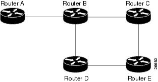
If parallel native IP paths and paths over TE tunnels are available, the following implementations allow you to force traffic to flow over TE tunnels only or only over native IP paths. Assume that all links have the same cost and that a TE tunnel is set up from Router A to Router D.
- When the SPF calculation puts Router C on the TENT list, it realizes that Router C is not directly connected. It uses the first-hop information from the parent, which is Router B.
- When the SPF calculation on Router A puts Router D on the TENT list, it realizes that Router D is the tail end of a TE tunnel. Thus Router A installs a route to Router D by the TE tunnel, and not by Router B.
- When Router A puts Router E on the TENT list, it realizes that Router E is not directly connected, and that Router E is not the tail end of a TE tunnel. Therefore Router A copies the first-hop information from the parents (Router C and Router D) to the first-hop information of Router E.
Traffic to Router E now load balances over
Additional Enhancements to SPF Computation Using Configured Tunnel Metrics
When traffic engineering tunnels install an IGP route in a Router Information Base (RIB) as next hops, the distance or metric of the route must be calculated. Normally, you could make the metric the same as the IGP metric over native IP paths as if the TE tunnels did not exist. For example, Router A can reach Router C with the shortest distance of 20. X is a route advertised in IGP by Router C. Route X is installed in Router A's RIB with the metric of 20. When a TE tunnel from Router A to Router C comes up, by default the route is installed with a metric of 20, but the next-hop information for X is changed.
Although the same metric scheme can work well in other situations, for some applications it is useful to change the TE tunnel metric (for instance, when there are equal cost paths through TE tunnel and native IP links). You can adjust TE tunnel metrics to force the traffic to prefer the TE tunnel, to prefer the native IP paths, or to load share among them.
Suppose that multiple TE tunnels go to the same destination or different destinations. TE tunnel metrics can force the traffic to prefer some TE tunnels over others, regardless of IGP distances to those destinations.
Setting metrics on TE tunnels does not affect the basic SPF algorithm. It affects only two questions:
- Is the TE tunnel installed as one of the next hops to the destination routers?
- What is the metric value of the routes being installed into the RIB?
You can modify the metrics for determining the first-hop information in one of the following ways:
- If the metric of the TE tunnel to the tailend routers is higher than the metric for the other TE tunnels or native hop-by-hop IGP paths, this tunnel is not installed as the next hop.
- If the metric of the TE tunnel is equal to the metric of either other TE tunnels or native hop-by-hop IGP paths, this tunnel is added to the existing next hops.
- If the metric of the TE tunnel is lower than the metric of other TE tunnels or native hop-by-hop IGP paths, this tunnel replaces them as the only next hop.
In each of the above cases, the IGP assigns metrics to routes associated with those tailend routers and their downstream routers.
The SPF computation is loop free because the traffic through the TE tunnels is basically source routed. The end result of TE tunnel metric adjustment is the control of traffic loadsharing. If there is only one way to reach the destination through a single TE tunnel, then no matter what metric is assigned, the traffic has only one way to go.
You can represent the TE tunnel metric in two different ways: (1) as an absolute (or fixed) metric or (2) as a relative (or floating) metric.
If you use an absolute metric, the routes assigned with the metric are fixed. This metric is used not only for the routes sourced on the TE tunnel tailend router, but also for each route downstream of this tailend router that uses this TE tunnel as one of its next hops.
For example, if you have TE tunnels to two core routers in a remote point of presence (POP), and one of them has an absolute metric of 1, all traffic going to that POP traverses this low-metric TE tunnel.
If you use a relative metric, the actual assigned metric value of routes is based on the IGP metric. This relative metric can be positive or negative, and is bounded by minimum and maximum allowed metric values. For example, assume the topology shown in the figure below.
| Figure 2 | Topology That Has No Traffic Engineering Tunnel |
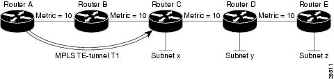
If there is no TE tunnel, Router A installs routes x, y, and z and assigns metrics 20, 30, and 40 respectively. Suppose that Router A has a TE tunnel T1 to Router C. If the relative metric -5 is used on tunnel T1, the routes x, y, and z have the installed metrics of 15, 25, and 35. If an absolute metric of 5 is used on tunnel T1, routes x, y and z have the same metric 5 installed in the RIB for Router A. The assigning of no metric on the TE tunnel is a special case, a relative metric scheme where the metric is 0.
Transition of an IS-IS Network to a New Technology
IS-IS, as specified in RFC 1142, includes extensions for MPLS traffic engineering and for other purposes. Running MPLS traffic engineering over IS-IS or taking advantage of these other extensions requires transitioning an IS-IS network to this new technology. This section describes these extensions and discusses two ways to migrate an existing IS-IS network from the standard ISO 10589 protocol towards the version of IS-IS specified in RFC 1142.Running MPLS traffic engineering over an existing IS-IS network requires a transition to the version of IS-IS specified in RFC 1142. However, running MPLS traffic engineering over OSPF does not require any similar network transition.
This section contains information about the following topics:
- Extensions for the IS-IS Routing Protocol
- Problems with Old and New TLVs in Theory and in Practice
- First Solution for Transitioning an IS-IS Network to a New Technology
- Transition Actions During the First Solution
- Second Solution for Transitioning an IS-IS Network to a New Technology
- Transition Actions During the Second Solution
- TLV Configuration Commands
Extensions for the IS-IS Routing Protocol
Extensions for the IS-IS routing protocol serve the following purposes:
- Remove the 6-bit limit on link metrics.
- Allow interarea IP routes.
- Enable IS-IS to carry different kinds of information for traffic engineering. In the future, more extensions might be needed.
To serve these purposes, two new TLVs (type, length, and value objects) have been defined:
- TLV 22 describes links (or rather adjacencies). It serves the same purpose as the "IS neighbor option" in ISO 10589 (TLV 2).
- TLV 135 describes reachable IP prefixes. It is similar to the IP Neighbor options from RFC 1195 (TLVs 128 and 130).
 Note |
For the purpose of briefness, these two new TLVs, 22 and 135, are referred to as "new-style TLVs." TLVs 2, 128, and 130 are referred to as "old-style TLVs." |
Both new TLVs have a fixed length part, followed by optional sub-TLVs. The metric space in these new TLVs has been enhanced from 6 bits to 24 or 32 bits. The sub-TLVs allow you to add new properties to links and prefixes. Traffic engineering is the first technology to use this ability to add new properties to a link.
Problems with Old and New TLVs in Theory and in Practice
Link-state routing protocols compute loop-free routes. This is guaranteed because all routers calculate their routing tables based on the same information from the link-state database (LSPDB).
There is a problem when some routers look at old-style TLVs and some routers look at new-style TLVs because the routers can base their SPF calculations on different information. This can cause routing loops.
The easiest way to migrate from old-style TLVs towards new-style TLVs would be to introduce a "flag day." A flag day means that you reconfigure all routers during a short period of time, during which service is interrupted. If the implementation of a flag day is not acceptable, a network administrator needs to find a viable solution for modern existing networks.
Network administrators have the following problems related to TLVs:
- They need to run an IS-IS network where some routers are advertising and using the new-style TLVs and, at the same time, other routers are capable only of advertising and using old-style TLVs.
- They need to test new traffic engineering software in existing networks on a limited number of routers. They cannot upgrade all their routers in their production networks or in their test networks before they start testing.
The new extensions allow a network administrator to use old-style TLVs in one area, and new-style TLVs in another area. However, this is not a solution for administrators who need or want to run their network in one single area.
The following sections describe two solutions to the network administrator's problems.
First Solution for Transitioning an IS-IS Network to a New Technology
When you migrate from old-style TLVs towards new-style TLVs, you can advertise the same information twice--once in old-style TLVs and once in new-style TLVs. This ensures that all routers can understand what is advertised.
There are three disadvantages to using that approach:
- Size of the LSPs--During the transition, the LSPs grow to about twice their original size. This might be a problem in networks where the LSPDB is large. An LSPDB might be large because
- There are many routers, and thus LSPs.
- There are many neighbors or IP prefixes per router. A router that advertises lots of information causes the LSPs to be fragmented.
- Unpredictable results--In a large network, this solution can produce unpredictable results. A large network in transition pushes the limits regarding LSP flooding and SPF scaling. During the transition
- You can expect some extra network instability. At this time, you especially do not want to test how far you can push an implementation.
- Traffic engineering extensions might cause LSPs to be reflooded frequently.
- Ambiguity--If a router encounters different information in the old-style TLVs and the new-style TLVs, it may not be clear what the router should do.
These problems can be largely solved easily by using
- All information in old-style and new-style TLVs in an LSP
- The adjacency with the lowest link metric if an adjacency is advertised more than once
The main benefit to advertising the same information twice is that network administrators can use new-style TLVs before all routers in the network can understand them.
Transition Actions During the First Solution
When transitioning from using IS-IS with old-style TLVs to new-style TLVs, you can perform the following actions:
- If all routers run old software, advertise and use only old-style TLVs.
- Upgrade some routers to newer software.
- Configure some routers with new software to advertise both old-style and new-style TLVs. They accept both styles of TLVs. Configure other routers (with old software) to continue advertising and using only old-style TLVs.
- Test traffic engineering in parts of your network; however, new-style TLVs cannot be used yet.
- If the whole network needs to migrate, upgrade and configure all remaining routers to advertise and accept both styles of TLVs.
- Configure all routers to advertise and accept only new-style TLVs.
- Configure metrics larger than 63.
For more information about how to perform these actions, see the TLV Configuration Commands section.
Second Solution for Transitioning an IS-IS Network to a New Technology
Routers advertise only one style of TLVs at the same time, but can understand both types of TLVs during migration. There are two main benefits to this approach:
- LSPs stay approximately the same size during migration.
- There is no ambiguity when the same information is advertised twice inside one LSP.
This method is useful when you are transitioning the whole network (or a whole area) to use wider metrics (that is, you want a router running IS-IS to generate and accept only new-style TLVs). For more information, see the metric-style widecommand.
The disadvantage is that all routers must understand the new-style TLVs before any router can start advertising new-style TLVs. It does not help the second problem, where network administrators want to use the new-style TLVs for traffic engineering, while some routers are capable of understanding only old-style TLVs.
Transition Actions During the Second Solution
If you use the second solution, you can perform the following actions:
- If all routers run old software, advertise and use only old-style TLVs.
- Upgrade all routers to newer software.
- Configure all routers one-by-one to advertise old-style TLVs, but to accept both styles of TLVs.
- Configure all routers one-by-one to advertise new-style TLVs, but to accept both styles of TLVs.
- Configure all routers one-by-one to advertise and to accept only new-style TLVs.
- Configure metrics larger than 63.
TLV Configuration Commands
Cisco IOS has a router isiscommand-line interface (CLI) command called metric-style. Once the router is in IS-IS configuration mode, you have the option to choose the following:
- metric-style narrow --Enables the router to generate and accept only old-style TLVs
- metric-style transition --Enables the router to generate and accept both old-style and new-style TLVs
- metric-style wide --Enables the router to generate and accept only new-style TLVs
You can use either of the following two transition schemes when you use the metric-stylecommand to configure:
- Narrow to transition to wide
- Narrow to narrow transition to wide transition to wide
How to Configure MPLS Traffic Engineering and Enhancements
- Configuring a Device to Support Tunnels
- Configuring an Interface to Support RSVP-Based Tunnel Signaling and IGP Flooding
- Configuring IS-IS for MPLS Traffic Engineering
- Configuring OSPF for MPLS Traffic Engineering
- Configuring an MPLS Traffic Engineering Tunnel
- Configuring an MPLS Traffic Engineering Tunnel that an IGP Can Use
Configuring a Device to Support Tunnels
DETAILED STEPS
Configuring an Interface to Support RSVP-Based Tunnel Signaling and IGP Flooding
Note |
You must enable the tunnel feature on interfaces that you want to support MPLS traffic engineering. |
DETAILED STEPS
Configuring IS-IS for MPLS Traffic Engineering
To configure IS-IS for MPLS traffic engineering, perform the following steps.
Note |
MPLS traffic engineering supports only a single IGP process/instance. Multiple IGP processes/instances are not supported and MPLS traffic engineering should not be configured in more than one IGP process/instance. |
DETAILED STEPS
| Command or Action | Purpose | |
|---|---|---|
|
|
|
Enables IS-IS routing and specifies an IS-IS process for IP. The router is placed in configuration mode. |
|
|
|
Turns on MPLS traffic engineering for IS-IS level 1. |
|
|
|
Turns on MPLS traffic engineering for IS-IS level 2. |
|
|
|
Specifies that the traffic engineering router identifier for the node is the IP address associated with interface loopback0. |
|
|
|
Configures a router to generate and accept only new-style type, length, value objects (TLVs). |
Configuring OSPF for MPLS Traffic Engineering
DETAILED STEPS
Configuring an MPLS Traffic Engineering Tunnel
This tunnel has two path setup options: a preferred explicit path and a backup dynamic path.
DETAILED STEPS
DEFAULT STEPS
DETAILED STEPS
| Command or Action | Purpose | |
|---|---|---|
|
|
Example: Router> enable |
Enables privileged EXEC mode.
|
|
|
Example: Router# configure terminal |
Enters global configuration mode. |
|
|
Example: Router(config)# interface tunnel10 |
Configures an interface type and enters interface configuration mode. |
|
|
Example: Router(config-if)# ip unnumbered loopback 0 |
Gives the tunnel interface an IP address.
|
|
|
Example: Router(config-if)# tunnel destination 10.20.1.1 |
Specifies the destination for a tunnel.
|
|
|
Example: Router(config-if)# tunnel mode mpls traffic-eng |
Sets the tunnel encapsulation mode to MPLS traffic engineering. |
|
|
Example: Router(config-if)# tunnel mpls traffic-eng bandwidth 1000 |
Configures the bandwidth for the MPLS traffic engineering tunnel. |
|
|
Example: Router(config-if)# tunnel mpls traffic-eng path-option 1 explicit identifier 1 |
Configures the tunnel to use a named IP explicit path or a path dynamically calculated from the traffic engineering topology database.
|
|
|
Example: Router(config-if)# exit |
Exits interface configuration mode and returns to global configuration mode. |
|
|
Example: Router(config)# exit |
Exits global configuration mode and returns to privileged EXEC mode. |
Configuring an MPLS Traffic Engineering Tunnel that an IGP Can Use
This tunnel has two path setup options: a preferred explicit path and a backup dynamic path.
DEFAULT STEPS
DETAILED STEPS
| Command or Action | Purpose | |
|---|---|---|
|
|
Example: Router> enable |
Enables privileged EXEC mode.
|
|
|
Example: Router# configure terminal |
Enters global configuration mode. |
|
|
Example: Router(config)# interface tunnel1 |
Configures an interface type and enters interface configuration mode. |
|
|
Example: Router(config-if)# tunnel mpls traffic-eng autoroute announce |
Causes the IGP to use the tunnel in its enhanced SPF calculation. |
|
|
Example: Router(config-if)# exit |
Exits interface configuration mode and returns to global configuration mode. |
|
|
Example: Router(config)# exit |
Exits global configuration mode and returns to privileged EXEC mode. |
Configuration Examples for MPLS Traffic Engineering and Enhancements
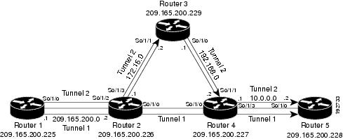
The figure below illustrates a sample MPLS topology. This example specifies point-to-point outgoing interfaces. The next sections contain sample configuration commands you enter to implement MPLS traffic engineering and the basic tunnel configuration shown in Figure 3.
| Figure 3 | Sample MPLS Traffic Engineering Tunnel Configuration |
- Configuring MPLS Traffic Engineering Using IS-IS Example
- Configuring MPLS Traffic Engineering Using OSPF Example
- Configuring an MPLS Traffic Engineering Tunnel Example
- Configuring Enhanced SPF Routing over a Tunnel Example
Configuring MPLS Traffic Engineering Using IS-IS Example
This example lists the commands you enter to configure MPLS traffic engineering with IS-IS routing enabled (see the figure above).
Note |
You must enter the following commands on every router in the traffic-engineered portion of your network. |
Router 1--MPLS Traffic Engineering Configuration
To configure MPLS traffic engineering, enter the following commands:
ip cef
mpls traffic-eng tunnels
interface loopback 0
ip address 10.0.0.0 255.255.255.254
ip router isis
interface s1/0/0
ip address 209.165.200.1 255.255.0.0
ip router isis
mpls traffic-eng tunnels
ip rsvp bandwidth 1000
Router 1--IS-IS Configuration
To enable IS-IS routing, enter the following commands:
router isis
network 47.0000.0011.0011.00
is-type level-1
metric-style wide
mpls traffic-eng router-id loopback0
mpls traffic-eng level-1
Configuring MPLS Traffic Engineering Using OSPF Example
This example lists the commands you enter to configure MPLS traffic engineering with OSPF routing enabled (see the figure above).
Note |
You must enter the following commands on every router in the traffic-engineered portion of your network. |
Router 1--MPLS Traffic Engineering Configuration
To configure MPLS traffic engineering, enter the following commands:
ip cef
mpls traffic-eng tunnels
interface loopback 0
ip address 209.165.200.225 255.255.255.255
interface s1/0/0
ip address 209.165.200.1 255.255.0.0
mpls traffic-eng tunnels
  ip rsvp bandwidth 1000
Router 1--OSPF Configuration
To enable OSPF, enter the following commands:
router ospf 0
network 209.165.200.0.0.0.255.255 area 0
mpls traffic-eng router-id Loopback0
mpls traffic-eng area 0
Configuring an MPLS Traffic Engineering Tunnel Example
This example shows you how to configure a dynamic path tunnel and an explicit path in the tunnel. Before you configure MPLS traffic engineering tunnels, you must enter the appropriate global and interface commands on the specified router (in this case, Router 1).
- Router 1--Dynamic Path Tunnel Configuration
- Router 1--Dynamic Path Tunnel Verification
- Router 1--Explicit Path Configuration
- Router 1--Explicit Path Tunnel Configuration
- Router 1--Explicit Path Tunnel Verification
Router 1--Dynamic Path Tunnel Configuration
In this section, a tunnel is configured to use a dynamic path.
interface tunnel1
  ip unnumbered loopback 0
  tunnel destination 209.165.200.228
  tunnel mode mpls traffic-eng
tunnel mpls traffic-eng bandwidth 100
  tunnel mpls traffic-eng priority 1 1
  tunnel mpls traffic-eng path-option 1 dynamic
Router 1--Dynamic Path Tunnel Verification
This section includes the commands you use to verify that the tunnel is up.
show mpls traffic-eng tunnels
show ip interface tunnel1
Router 1--Explicit Path Configuration
In this section, an explicit path is configured.
ip explicit-path identifier 1
 next-address 209.165.200.1
 next-address 172.16.0.1
 next-address 192.168.0.1
 next-address 10.0.0.1
Router 1--Explicit Path Tunnel Configuration
In this section, a tunnel is configured to use an explicit path.
interface tunnel2
  ip unnumbered loopback 0
  tunnel destination 209.165.200.228
  tunnel mode mpls traffic-eng
tunnel mpls traffic-eng bandwidth 100
  tunnel mpls traffic-eng priority 1 1
  tunnel mpls traffic-eng path-option 1 explicit identifier 1
Router 1--Explicit Path Tunnel Verification
This section includes the commands you use to verify that the tunnel is up.
show mpls traffic-eng tunnels
show ip interface tunnel2
Configuring Enhanced SPF Routing over a Tunnel Example
This section includes the commands that cause the tunnel to be considered by the IGP's enhanced SPF calculation, which installs routes over the tunnel for appropriate network prefixes.
Router 1--IGP Enhanced SPF Consideration Configuration
In this section, you specify that the IGP should use the tunnel (if the tunnel is up) in its enhanced shortest path first (SPF) calculation.
interface tunnel1
tunnel mpls traffic-eng autoroute announce
Router 1--Route and Traffic Verification
This section includes the commands you use to verify that the tunnel is up and that the traffic is routed through the tunnel.
show traffic-eng tunnels tunnel1 brief
show ip route 209.165.200.228
show mpls traffic-eng autoroute
ping 209.165.200.228
show interface tunnel1 accounting
show interface s1/0/0 accounting
Additional References
The following sections provide references related to the MPLS Traffic Engineering and Enhancements feature.
Related Documents
| Related Topic |
Document Title |
|---|---|
| IS-IS commands |
Cisco IOS IP Routing Protocols Command Reference |
| OSPF command |
Cisco IOS IP Routing Protocols Command Reference |
| MPLS TE commands |
Cisco IOS Multiprotocol Label Switching Command Reference |
| RSVP commands |
Cisco IOS Quality of Service Solutions Command Reference |
Standards
| Standard |
Title |
|---|---|
| None |
-- |
MIBs
| MIB |
MIBs Link |
|---|---|
| None |
To locate and download MIBs for selected platforms, Cisco IOS software releases, and feature sets, use Cisco MIB Locator found at the following URL: |
RFCs
| RFC |
Title |
|---|---|
| 1142 |
IS-IS |
| 1195 |
Use of OSI IS-IS for Routing in TCP/IP and Dual Environments |
| 2205 |
Resource ReSerVation Protocol (RSVP) |
| 2328 |
OSPF Version 2 |
| 2370 |
The OSPF Opaque LSA Option |
Technical Assistance
| Description |
Link |
|---|---|
| The Cisco Support website provides extensive online resources, including documentation and tools for troubleshooting and resolving technical issues with Cisco products and technologies. To receive security and technical information about your products, you can subscribe to various services, such as the Product Alert Tool (accessed from Field Notices), the Cisco Technical Services Newsletter, and Really Simple Syndication (RSS) Feeds. Access to most tools on the Cisco Support website requires a Cisco.com user ID and password. |
Feature Information for MPLS Traffic Engineering and Enhancements
The following table provides release information about the feature or features described in this module. This table lists only the software release that introduced support for a given feature in a given software release train. Unless noted otherwise, subsequent releases of that software release train also support that feature.
Use Cisco Feature Navigator to find information about platform support and Cisco software image support. To access Cisco Feature Navigator, go to www.cisco.com/go/cfn. An account on Cisco.com is not required.
| Table 1 | Feature Information for MPLS Traffic Engineering and Enhancements |
| Feature Name |
Releases |
Feature Information |
|---|---|---|
| MPLS Traffic Engineering and Enhancements |
12.0(6)T) 12.0(5)S 12.1(2)E 12.2(28)SB2 12.2(46)SE |
Multiprotocol Label Switching (MPLS) traffic engineering software enables an MPLS backbone to replicate and expand upon the traffic engineering capabilities of Layer 2 ATM and Frame Relay networks. MPLS is an integration of Layer 2 and Layer 3 technologies. By making traditional Layer 2 features available to Layer 3, MPLS enables traffic engineering. Thus, you can offer in a one-tier network what previously could be achieved only by overlaying a Layer 3 network on a Layer 2 network. This feature was introduced in Cisco IOS Release 12.0(6)T. This feature was integrated into Cisco IOS Release 12.0(5)S. This feature was integrated into Cisco IOS Release 12.1(2)E. This feature was integrated into Cisco IOS Release 12.2(28)SB2. This feature was integrated into Cisco IOS Release 12.2(46)SE. |
|
|
|
The following commands were introduced or modified:ip explicit-path, metric-style narrow, metric-style transition, metric-style wide, mpls traffic-eng, mpls traffic-eng area, mpls traffic-eng router-id, mpls traffic-eng tunnels (configuration), mpls traffic-eng tunnels (interface), show mpls traffic-eng autoroute, show mpls traffic-eng tunnels, tunnel mode mpls traffic-eng, tunnel mode mpls traffic-eng autoroute announce, tunnel mpls traffic-eng bandwidth, tunnel mpls traffic-eng path-option, tunnel mpls traffic-eng priority. |
Glossary
affinity --An MPLS traffic engineering tunnel's requirements on the attributes of the links it will cross. The tunnel's affinity bits and affinity mask bits must match the attribute bits of the various links carrying the tunnel.
call admission precedence --An MPLS traffic engineering tunnel with a higher priority will, if necessary, preempt an MPLS traffic engineering tunnel with a lower priority. Tunnels that are harder to route are expected to have a higher priority and to be able to preempt tunnels that are easier to route. The assumption is that lower-priority tunnels will be able to find another path.
constraint-based routing --Procedures and protocols that determine a route across a backbone take into account resource requirements and resource availability instead of simply using the shortest path.
flow --A traffic load entering the backbone at one point--point of presence (POP)--and leaving it from another, that must be traffic engineered across the backbone. The traffic load is carried across one or more LSP tunnels running from the entry POP to the exit POP.
headend --The upstream, transmit end of a tunnel.
IGP --Interior Gateway Protocol. The Internet protocol used to exchange routing information within an autonomous system. Examples of common IGPs include IGRP, OSPF, and RIP.
ip explicit path --A list of IP addresses, each representing a node or link in the explicit path.
IS-IS --Intermediate System-to-Intermediate System. OSI link-state hierarchical routing protocol that calls for intermediate system (IS) routers to exchange routing information based on a single metric to determine network topology.
label switched path (LSP) --A sequence of hops (R0...Rn) in which a packet travels from R0 to Rn through label switching mechanisms. A label switched path can be chosen dynamically, based on normal routing mechanisms, or through configuration.
label switched path (LSP) tunnel --A configured connection between two routers, in which label switching is used to carry the packets.
label switching router (LSR) --A Layer 3 router that forwards packets based on the value of a label encapsulated in the packets.
LCAC --Link-level (per hop) call admission control.
LSA --Link-state advertisement. Flooded packet used by OSPF that contains information about neighbors and path costs. In IS-IS, receiving routers use LSAs to maintain their routing tables.
LSP--See label switched path.
OSPF protocol --Open Shortest Path First. A link state routing protocol used for routing IP.
reoptimization--Reevaluation of the most suitable path for a tunnel to use, given the specified constraints.
RSVP --Resource Reservation Protocol. A protocol for reserving network resources to provide quality of service guarantees to application flows.
tailend --The downstream, receive end of a tunnel.
traffic engineering --Techniques and processes that cause routed traffic to travel through the network on a path other than the one that would have been chosen if standard routing methods were used.
Cisco and the Cisco logo are trademarks or registered trademarks of Cisco and/or its affiliates in the U.S. and other countries. To view a list of Cisco trademarks, go to this URL: www.cisco.com/go/trademarks. Third-party trademarks mentioned are the property of their respective owners. The use of the word partner does not imply a partnership relationship between Cisco and any other company. (1110R)
Any Internet Protocol (IP) addresses and phone numbers used in this document are not intended to be actual addresses and phone numbers. Any examples, command display output, network topology diagrams, and other figures included in the document are shown for illustrative purposes only. Any use of actual IP addresses or phone numbers in illustrative content is unintentional and coincidental.
 Feedback