IP Multicast: MVPN Configuration Guide, Cisco IOS XE Release 2
Bias-Free Language
The documentation set for this product strives to use bias-free language. For the purposes of this documentation set, bias-free is defined as language that does not imply discrimination based on age, disability, gender, racial identity, ethnic identity, sexual orientation, socioeconomic status, and intersectionality. Exceptions may be present in the documentation due to language that is hardcoded in the user interfaces of the product software, language used based on RFP documentation, or language that is used by a referenced third-party product. Learn more about how Cisco is using Inclusive Language.
- Updated:
- July 13, 2017
Chapter: Configuring Multicast VPN Extranet Support
- Finding Feature Information
- Prerequisites for Configuring Multicast VPN Extranet Support
- Restrictions for Configuring Multicast VPN Extranet Support
- Information About Multicast VPN Extranet Support
- How to Configure Multicast VPN Extranet Support
- Configuration Examples for Multicast VPN Extranet Support
- Additional References
- Feature Information for Configuring Multicast VPN Extranet Support
- Finding Feature Information
Configuring Multicast VPN Extranet Support
The Multicast VPN Extranet Support feature (sometimes referred to as the MVPN Extranet Support feature) enables service providers to distribute IP multicast content originated from one enterprise site to other enterprise sites. This feature enables service providers to offer the next generation of flexible extranet services, helping to enable business partnerships between different enterprise VPN customers.
This module describes the concepts and the tasks related to configuring Multicast VPN Extranet Support.
- Finding Feature Information
- Prerequisites for Configuring Multicast VPN Extranet Support
- Restrictions for Configuring Multicast VPN Extranet Support
- Information About Multicast VPN Extranet Support
- How to Configure Multicast VPN Extranet Support
- Configuration Examples for Multicast VPN Extranet Support
- Additional References
- Feature Information for Configuring Multicast VPN Extranet Support
Finding Feature Information
Your software release may not support all the features documented in this module. For the latest feature information and caveats, see the release notes for your platform and software release. To find information about the features documented in this module, and to see a list of the releases in which each feature is supported, see the Feature Information Table at the end of this document.
Use Cisco Feature Navigator to find information about platform support and Cisco software image support. To access Cisco Feature Navigator, go to www.cisco.com/go/cfn. An account on Cisco.com is not required.
Prerequisites for Configuring Multicast VPN Extranet Support
- You are familiar with IP multicast concepts and configuration tasks.
- You are familiar with Multicast VPN (MVPN) concepts and configuration tasks.
- You are familiar with Multiprotocol Label Switching (MPLS) Layer 3 Virtual Private Network (VPN) concepts and configuration tasks.
Restrictions for Configuring Multicast VPN Extranet Support
- The Multicast VPN Extranet Support feature supports only Protocol Independent Multicast (PIM) sparse mode (PIM-SM) and Source Specific Multicast (SSM) traffic; PIM dense mode (PIM-DM) and bidirectional PIM (bidir-PIM) traffic are not supported.
- When configuring extranet MVPNs in a PIM-SM environment, the source and the rendezvous point (RP) must reside in the same site of the MVPN behind the same provider edge (PE) router.
Information About Multicast VPN Extranet Support
- Overview of MVPN Extranet Support
- Configuration Guidelines for MVPN Extranet Support
- Multicast VPN Extranet VRF Select
Overview of MVPN Extranet Support
An extranet can be viewed as part of a company's intranet that is extended to users outside the company. It has also been described as a "state of mind" in which a VPN is used as a way to do business with other companies and to sell products and content to customers and companies. An extranet is a VPN connecting the corporate site or sites to external business partners or suppliers to securely share part of a business's information or operations among them.
MPLS VPNs inherently provide security, ensuring that users access only appropriate information. MPLS VPN extranet services offer extranet users unicast connectivity without compromising the integrity of their corporate data. The Multicast VPN Extranet Support feature extends this offer to include multicast connectivity to the extranet community of interest.
The Multicast VPN Extranet Support feature enables service providers to distribute IP multicast content originated from one enterprise site to other enterprise sites. This feature enables service providers to offer the next generation of flexible extranet services, helping to enable business partnerships between different enterprise VPN customers. Using this feature, service providers can offer multicast extranet contracts to meet various business partnership requirements, including short-term, annual, and rolling contracts.
Benefits of MVPN Extranet Support
The Multicast VPN Extranet Support feature can be used to solve such business problems as:
- Efficient content distribution between enterprises
- Efficient content distribution from service providers or content providers to their different enterprise VPN customers
Components of an Extranet MVPN
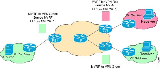
The figure illustrates the components that constitute an extranet MVPN:
- MVRF --Multicast VPN routing and forwarding (VRF) instance. An MVRF is a multicast-enabled VRF. A VRF consists of an IP routing table, a derived forwarding table, a set of interfaces that use the forwarding table, and a set of rules and routing protocols that determine what goes into the forwarding table. In general, a VRF includes the routing information that defines a customer VPN site that is attached to a provider edge (PE) router.
- Source MVRF --An MVRF that can reach the source through a directly connected customer edge (CE) router.
- Receiver MVRF --An MVRF to which receivers are connected through one or more CE devices.
- Source PE --A PE router that has a multicast source behind a directly connected CE router.
- Receiver PE --A PE router that has one or more interested receivers behind a directly connected CE router.
| Figure 1 | Components of an Extranet MVPN |
Solution for MVPN Extranet Support
For unicast, there is no difference between an intranet or extranet from a routing perspective; that is, when a VRF imports a prefix, that prefix is reachable through a label-switched path (LSP). If the enterprise owns the prefix, the prefix is considered a part of the corporate intranet; otherwise, the prefix is considered a part of an extranet. For multicast, however, the reachability of a prefix (especially through an LSP) is not sufficient to build a multicast distribution tree (MDT).
In order to provide support for extranet MVPN services, the same default MDT group must be configured in the source and receiver MVRF. Prior to the introduction of the Multicast VPN Extranet Support feature, there were challenges that prevented service providers from providing extranet MVPN services:
- The source MVRF may not have been configured with a default MDT group, or it may have been configured with a different MDT group as compared to the receiver MVRF. In the former case there was no way for the source MVRF to forward multicast streams to extranet sites, and in the latter case, there was no way for the separate MVRFs to be linked.
- It was not possible to maintain a forwarding table in cases where the RPF interface and outgoing interfaces belong to different VRFs.
The Multicast VPN Extranet Support feature solves these challenges as follows:
- The receiver and source MVRF multicast route (mroute) entries are linked.
- The Reverse Path Forwarding (RPF) check relies on unicast routing information to determine the interface through which the source is reachable. This interface is used as the RPF interface.
Configuration Guidelines for MVPN Extranet Support
Two configuration options are available to provide extranet MVPN services:
- Option 1--Configure the receiver MVRF on the source PE router.
- Option 2--Configure the source MVRF on the receiver PE router.
- MVPN Extranet Support Configuration Guidelines for Option 1
- MVPN Extranet Support Configuration Guidelines for Option 2
- RPF for MVPN Extranet Support Using Imported Routes
- RPF for MVPN Extranet Support Using Static Mroutes
MVPN Extranet Support Configuration Guidelines for Option 1
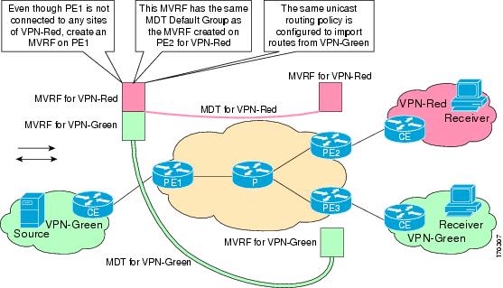
To provide extranet MVPN services to enterprise VPN customers by configuring the receiver MVRF on the source PE router (Option 1), you would complete the following procedure:
- For each extranet site, you would configure an additional MVRF on the source PE router, that has the same default MDT group as the receiver MVRF, if the MVRF is not configured on the source PE.
- In the receiver MVRF configuration, you would configure the same unicast routing policy on the source and receiver PE routers to import routes from the source MVRF to the receiver MVRF.
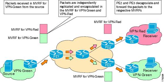
The figure illustrates the flow of multicast traffic in an extranet MVPN topology where a receiver MVRF is configured on the source PE router (Option 1). In the topology, an MVRF is configured for VPN-Green and VPN-Red on PE1, the source PE router. A multicast source behind PE1 is sending out a multicast stream to the MVRF for VPN-Green, and there are interested receivers behind PE2 and PE3, the receiver PE routers for VPN-Red and VPN-Green, respectively. After PE1 receives the packets from the source in the MVRF for VPN-Green, it independently replicates and encapsulates the packets in the MVRF for VPN-Green and VPN-Red and forwards the packets. After receiving the packets from this source, PE2 and PE3 decapsulate and forward the packets to the respective MVRFs.
| Figure 2 | Packet Flow for MVPN Extranet Support Configuration Option 1 |
MVPN Extranet Support Configuration Guidelines for Option 2
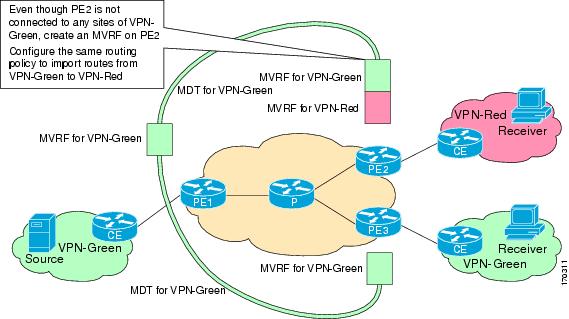
To provide extranet MVPN services to enterprise VPN customers by configuring a source MVRF on a receiver PE router (Option 2), you would complete the following procedure:
- On a receiver PE router that has one or more interested receivers in a extranet site behind a directly connected CE router, configure an additional MVRF that has the same default MDT group as the site connected to the multicast source, if the MVRF is not configured.
- On the receiver PE router, you would configure the same unicast routing policy to import routes from the source MVRF to the receiver MVRF.
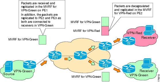
The figure illustrates the flow of multicast traffic in an extranet MVPN topology where the source MVRF is configured on a receiver PE router (Option 2). In the topology, an MVRF is configured for VPN-Green and VPN-Red on PE2, a receiver PE router. A multicast source behind PE1, the source PE router, is sending out a multicast stream to the MVRF for VPN-Green, and there are interested receivers behind PE2, the receiver PE router for VPN-Red, and behind PE3, the receiver PE router for VPN-Green. After PE1 receives the packets from the source in the MVRF for VPN-Green, it replicates and forwards the packets to PE2 and PE3, because both routers are connected to receivers in VPN-Green. The packets that originated from VPN-Green are then replicated on PE2 and forwarded to the interested receivers in VPN-Red and are replicated on PE3 and forwarded to the interested receivers in VPN-Green.
| Figure 3 | Packet Flow for MVPN Extranet Support Configuration Option 2 |
RPF for MVPN Extranet Support Using Imported Routes
You must configure either the receiver MVRF on the source PE router (Option 1) or the source MVRF on the receiver PE router (Option 2) for extranet links to be created. Once configured, RPF relies on unicast routing information to determine the interface through which the source is reachable. This interface is used as the RPF interface. No additional configuration is required for RPF resolution. The Multicast VPN Extranet Support feature supports RPF from one VRF to another VRF, from a VRF to the global routing table, and from the global routing table to a VRF.
RPF for MVPN Extranet Support Using Static Mroutes
By default, an extranet MVPN relies on unicast routing policies to determine the RPF interface. When the RPF lookup originates in a receiver MVRF, and it finds that the RPF interface does not lie in the same MVRF, the router uses the information in the Border Gateway Protocol (BGP) imported route to determine the source MVRF. The RPF lookup then continues and resolves in the source MVRF. In cases where the multicast and unicast topologies are incongruent, you can override the default behavior by configuring a static mroute in the receiver MVRF to explicitly specify the source MVRF using the ip mroute command with the fallback-lookup keyword and vrf vrf-name keyword and argument.
Static mroutes can also be configured to support RPF for extranet MVPN in the case where the source is present in an MVRF and the receiver is in the global table. In this case, because BGP does not allow VPNv4 routes to be imported into the IPv4 routing table, unicast cannot obtain the source MVRF information needed to resolve the RPF lookup. To enable the RPF lookup to be resolved in this case, a static mroute can be configured to explicitly specify the source MVRF using the ip mroute command with the fallback-lookup keyword and the global keyword.
Multicast VPN Extranet VRF Select
Prior to the introduction of the Multicast VPN Extranet VRF Select feature, RPF lookups for a source address could be performed only in a single VRF, that is, in the VRF where Internet Group Management Protocol (IGMP) or PIM joins are received, in the VRF learned from BGP imported routes, or in the VRF specified in static mroutes (when RPF for an extranet MVPN is configured using static mroutes). In those cases, the source VRF is solely determined by the source address or the way the source address was learned.
The Multicast VPN Extranet VRF Select feature provides the capability for RPF lookups to be performed to the same source address in different VRFs using the group address as the VRF selector. This feature enhances extranet MVPNs by enabling service providers to distribute content streams coming in from different MVPNs and redistributing them from there.
The Multicast VPN VRF Select feature is configured by creating group-based VRF selection policies. Group-based VRF selection policies are configured using the ip multicast rpf select command. The ip multicast rpf selectcommand is used to configure RPF lookups originating in a receiver MVRF or in the global routing table to be resolved in a source MVRF or in the global routing table based on group address. Access Control Lists (ACLs) are used to define the groups to be applied to group-based VRF selection policies.
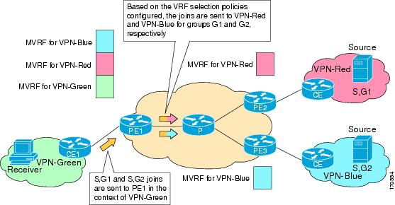
The figure illustrates an extranet MVPN topology with the Multicast VPN VRF Select feature configured. In this topology, (S, G1) and (S, G2) PIM joins originating from VPN-Green, the receiver VRF, are forwarded to PE1, the receiver PE. Based on the group-based VRF selection policies configured, PE1 sends the PIM joins to VPN-Red and VPN-Blue for groups G1 and G2, respectively.
| Figure 4 | RPF Lookups Using Group-Based VRF Selection Policies |
How to Configure Multicast VPN Extranet Support
- Configuring MVPN Extranet Support
- Configuring RPF for MVPN Extranet Support Using Static Mroutes
- Configuring Group-Based VRF Selection Policies with MVPN Extranet Support
Configuring MVPN Extranet Support
Perform this task to configure support for extranet MVPN services. Extranet MVPN services enable service providers to distribute IP multicast content originated from a corporate site to the sites of external business partners or suppliers.
Perform one of the following tasks to provide extranet MVPN capabilities:
- Prerequisites
- Restrictions
- Configuring the Receiver MVRF on the Source PE - Option 1
- Configuring the Source MVRF on the Receiver PE - Option 2
Prerequisites
- This task assumes that you have configured intranet VPN in the source and receiver VPNs.
Restrictions
- The Multicast VPN Extranet Support feature supports only PIM-SM and SSM traffic; PIM-DM and bidir-PIM traffic are not supported.
- When extranet MVPNs are configured in a PIM-SM environment, the source and the RP must reside in the same site of the MVPN behind the same PE router.
Configuring the Receiver MVRF on the Source PE - Option 1
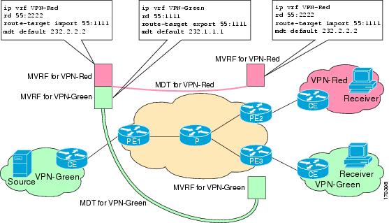
Perform this task to provide support for extranet MVPN services by configuring the receiver MVRF on the source PE router (Option 1).
The configuration for this task is done at PE1, the source PE router, in the figure. To provide extranet MVPN services from one enterprise VPN site (for example, VPN-Green) to another enterprise VPN site (for example, VPN-Red) using Option 1, you would configure the receiver MVRF on the source PE router. In the receiver MVRF configuration, the default MDT group must be the same on both the source and receiver PE routers. In addition, you would configure the same unicast routing policy to import routes from the source MVRF (for example, the MVRF for VPN-Green) to the receiver MVRF (for example, the MVRF for VPN-Red).
| Figure 5 | Topology for MVPN Extranet Support Configuration Option 1 |
DETAILED STEPS
Configuring the Source MVRF on the Receiver PE - Option 2
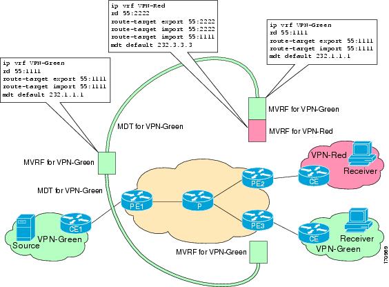
Perform this task to provide support for extranet MVPN services by configuring the source MVRF on the receiver PE router (Option 2).
The configuration for this task is done at PE2, the receiver PE router, in the figure below. To provide support for extranet MVPN services from one enterprise VPN site (for example, VPN-Green) to another enterprise VPN site (for example, VPN-Red) using Option 2, you would configure the source MVRF on the receiver PE router. The MDT group configuration of the source MVRF must be the same on both the source and receiver PE routers. In addition, you would configure the same unicast routing policy to import routes from the source MVRF (for example, the MVRF for VPN-Green) to the receiver MVRF (for example, the MVRF for VPN-Red).
| Figure 6 | Topology for MVPN Extranet Support Configuration Option 2 |
DETAILED STEPS
| Command or Action | Purpose | |||
|---|---|---|---|---|
|
|
Example: Router> enable |
Enables privileged EXEC mode. |
||
|
|
Example: Router# configure terminal |
Enters global configuration mode. |
||
|
|
Example: Router(config)# ip vrf VPN-Red |
Defines the VPN routing instance by assigning a VRF name and enters VRF configuration mode. |
||
|
|
Example: Router(config-vrf)# rd 55:1111 |
Creates routing and forwarding tables. |
||
|
|
Example: Router(config-vrf)# route-target import 55:1111 |
Creates a route-target extended community for a VRF.
|
||
|
|
Example: Router(config-vrf)# mdt default 232.1.1.1 |
Configures the multicast group address range for data MDT groups for a VRF. |
||
|
|
Example: Router(config-vrf)# end |
Exits VRF configuration mode and returns to privileged EXEC mode. |
||
|
|
Example: Router# show ip mroute 232.1.1.1 |
(Optional) Displays the contents of the IP multicast mroute table for a specific group address.
|
Configuring RPF for MVPN Extranet Support Using Static Mroutes
Perform this task to configure RPF for extranet MVPNs using static mroutes.
You must configure support for extranet MVPN services prior to performing this task.
DETAILED STEPS
| Command or Action | Purpose | |
|---|---|---|
|
|
Example: Router> enable |
Enables privileged EXEC mode.
|
|
|
Example: Router# configure terminal |
Enters global configuration mode. |
|
|
Example: Router(config)# ip mroute vrf VPN-Red 224.100.0.5 255.255.255.255 fallback-lookup vrf VPN-Green |
Configures the RPF lookup originating in a receiver MVRF to continue and be resolved in a source MVRF or in the global routing table using a static mroute.
|
|
|
Example: Router(config)# end |
Exits global configuration mode and enters privileged EXEC mode. |
|
|
Example: Router# show ip mroute 224.100.0.5 |
(Optional) Displays the contents of the IP multicast mroute table for a specific group address. |
Configuring Group-Based VRF Selection Policies with MVPN Extranet Support
Perform this task to configure group-based VRF selection policies with MVPN.
This task enables RPF lookups to be performed to the same source address in different VRFs using the group address as the VRF selector. This feature enhances extranet MVPNs by enabling service providers to distribute content streams coming in from different MVPNs and redistributing them from there.
- This task requires the routers to be running Cisco IOS XE Release 2.5 or a later release.
- You must configure support for extranet MVPN services prior to performing this task.
- ACLs are used to define the groups to be applied to group-based VRF selection policies. This task assumes that you have configured the ACLs to be applied to group-based VRF selection policies.
DETAILED STEPS
| Command or Action | Purpose | |
|---|---|---|
|
|
Example: Router> enable |
Enables privileged EXEC mode.
|
|
|
Example: Router# configure terminal |
Enters global configuration mode. |
|
|
Example: Router(config)# ip multicast vrf VPN-Green rpf select vrf VPN-Red group-list 1 |
Configures RPF lookups originating in a receiver MVRF or in the global routing table to be resolved in a source MVRF or in the global routing table based on group address.
|
|
|
|
-- |
|
|
Example: Router(config)# end |
Exits global configuration mode and enters privileged EXEC mode. |
|
|
Example: Router# show ip rpf select |
Displays group-to-VRF mapping information.
|
|
|
Example: Router# show ip rpf 172.16.10.13 |
Displays information about how IP multicast routing does RPF.
|
Configuration Examples for Multicast VPN Extranet Support
- Example Configuring the Receiver VRF on the Source PE Router - Option 1
- Example Configuring the Source VRF on the Receiver PE - Option 2
- Example Configuring RPF for MVPN Extranet Support Using Static Mroutes
- Example Configuring Group-Based VRF Selection Policies with MVPN Extranet Support
Example Configuring the Receiver VRF on the Source PE Router - Option 1
The following example shows the configurations for PE1, the source PE router, and PE2, the receiver PE router, in the figure. In this example, extranet MVPN services are supported between VPN-Green and VPN-Red by configuring the receiver MVRF for VPN-Red on PE1, the source PE router. The MVRF configuration for VPN-Red is configured to import routes from the MVRF for VPN-Green to the MVRF for VPN-Red.
| Figure 7 | Topology for MVPN Extranet Support Option 1 Configuration Example |
PE1 Configuration
ip cef
!
ip vrf VPN-Green
 rd 55:1111
 route-target export 55:1111
 route-target import 55:1111
 mdt default 232.1.1.1
!
ip vrf VPN-Red
 rd 55:2222
 route-target export 55:2222
 route-target import 55:2222
 route-target import 55:1111
 mdt default 232.3.3.3
!
ip multicast-routing
ip multicast-routing vrf VPN-Green
ip multicast-routing vrf VPN-Red
!
interface Loopback0
 ip address 10.1.0.1 255.255.255.0
 ip pim sparse-dense-mode
!
.
.
.
!
router bgp 55
 no synchronization
 bgp log-neighbor-changes
 neighbor 10.2.0.2 remote-as 55
 neighbor 10.2.0.2 update-source Loopback0
 !
 address-family ipv4 mdt
 neighbor 10.2.0.2 activate
 neighbor 10.2.0.2 send-community extended
 !
 address-family vpnv4
 neighbor 10.2.0.2 activate
 neighbor 10.2.0.2 send-community extended
 !
PE2 Configuration
!
ip vrf VPN-Red
 rd 55:2222
 route-target export 55:2222
 route-target import 55:2222
 route-target import 55:1111
 mdt default 232.3.3.3
!
ip multicast-routing
ip multicast-routing vrf VPN-Red
!
interface Loopback0
 ip address 10.2.0.2 255.255.255.0
 ip pim sparse-dense-mode
!
.
.
.
!
router bgp 55
 no synchronization
 bgp log-neighbor-changes
 neighbor 10.1.0.1 remote-as 55
 neighbor 10.1.0.1 update-source Loopback0
 !
 address-family ipv4 mdt
 neighbor 10.1.0.1 activate
 neighbor 10.1.0.1 send-community extended
 !
 address-family vpnv4
 neighbor 10.1.0.1 activate
 neighbor 10.1.0.1 send-community extended
 !
States in the Global Table on PE1 and PE2 for the MDT Default Group 232.3.3.3
The following are sample outputs from the show ip mroute command on PE1 and PE2. The sample outputs show the global table for the MDT default group 232.3.3.3 on PE1 and PE2.
PE1# show ip mroute 232.3.3.3
IP Multicast Routing Table
Flags: D - Dense, S - Sparse, B - Bidir Group, s - SSM Group, C - Connected,
       L - Local, P - Pruned, R - RP-bit set, F - Register flag,
       T - SPT-bit set, J - Join SPT, M - MSDP created entry,
       X - Proxy Join Timer Running, A - Candidate for MSDP Advertisement,
       U - URD, I - Received Source Specific Host Report,
       Z - Multicast Tunnel, z - MDT-data group sender,
       Y - Joined MDT-data group, y - Sending to MDT-data group
       V - RD & Vector, v - Vector
Outgoing interface flags: H - Hardware switched, A - Assert winner
 Timers: Uptime/Expires
 Interface state: Interface, Next-Hop or VCD, State/Mode
(10.1.0.1, 232.3.3.3), 00:46:27/00:03:27, flags: sT
  Incoming interface: Loopback0, RPF nbr 0.0.0.0
  Outgoing interface list:
    GigabitEthernet0/0, Forward/Sparse-Dense, 00:45:17/00:02:44
(10.2.0.2, 232.3.3.3), 00:45:17/00:02:57, flags: sTIZ
  Incoming interface: GigabitEthernet0/0, RPF nbr 224.0.1.4
  Outgoing interface list:
    MVRF VPN-Red, Forward/Sparse-Dense, 00:45:17/00:01:09
PE2# show ip mroute 232.3.3.3
IP Multicast Routing Table
Flags: D - Dense, S - Sparse, B - Bidir Group, s - SSM Group, C - Connected,
       L - Local, P - Pruned, R - RP-bit set, F - Register flag,
       T - SPT-bit set, J - Join SPT, M - MSDP created entry,
       X - Proxy Join Timer Running, A - Candidate for MSDP Advertisement,
       U - URD, I - Received Source Specific Host Report,
       Z - Multicast Tunnel, z - MDT-data group sender,
       Y - Joined MDT-data group, y - Sending to MDT-data group
       V - RD & Vector, v - Vector
Outgoing interface flags: H - Hardware switched, A - Assert winner
 Timers: Uptime/Expires
 Interface state: Interface, Next-Hop or VCD, State/Mode
(10.1.0.1, 232.3.3.3), 00:45:08/00:02:37, flags: sTIZ
  Incoming interface: GigabitEthernet1/0, RPF nbr 224.0.2.4
  Outgoing interface list:
    MVRF VPN-Red, Forward/Sparse-Dense, 00:45:08/00:01:27
(10.2.0.2, 232.3.3.3), 00:46:19/00:03:07, flags: sT
  Incoming interface: Loopback0, RPF nbr 0.0.0.0
  Outgoing interface list:
    GigabitEthernet1/0, Forward/Sparse-Dense, 00:45:08/00:02:49
States in the VRF Table for VPN-Green on PE1 After Receivers in VPN-Red Join Multicast Group 228.8.8.8
The following is sample output from the show ip mroute command on PE1. The sample output shows the state of the VRF table for VPN-Green on PE1 when receivers join the multicast group 228.8.8.8. The output indicates that extranet receivers in VPN-Red are receiving content from a source in VPN-Green that is sending to multicast group 228.8.8.8. The "E" flag in the output indicates that a (*, G) or (S, G) entry in the VRF routing table is a source VRF entry and has extranet receiver MVRF mroute entries linked to it.
PE1# show ip mroute vrf VPN-Green 228.8.8.8
IP Multicast Routing Table
Flags: D - Dense, S - Sparse, B - Bidir Group, s - SSM Group, C - Connected,
       L - Local, P - Pruned, R - RP-bit set, F - Register flag,
       T - SPT-bit set, J - Join SPT, M - MSDP created entry, E - Extranet,
       X - Proxy Join Timer Running, A - Candidate for MSDP Advertisement,
       U - URD, I - Received Source Specific Host Report,
       Z - Multicast Tunnel, z - MDT-data group sender,
       Y - Joined MDT-data group, y - Sending to MDT-data group,
       V - RD & Vector, v - Vector
Outgoing interface flags: H - Hardware switched, A - Assert winner
 Timers: Uptime/Expires
 Interface state: Interface, Next-Hop or VCD, State/Mode
(*, 228.8.8.8), 00:01:38/stopped, RP 10.100.0.5, flags: SE
  Incoming interface: GigabitEthernet3/0, RPF nbr 10.1.1.5
  Outgoing interface list: Null
  Extranet receivers in vrf VPN-Red:
(*, 228.8.8.8), 00:01:38/stopped, RP 10.100.0.5, OIF count: 1, flags: S
(10.1.1.200, 228.8.8.8), 00:00:05/00:02:54, flags: TE
  Incoming interface: GigabitEthernet3/0, RPF nbr 10.1.1.5
  Outgoing interface list: Null
  Extranet receivers in vrf VPN-Red:
  (10.1.1.200, 228.8.8.8), 00:00:05/stopped, OIF count: 1, flags:
States in the VRF Table for VPN-Red on PE1 After Receivers in VPN-Red Join Multicast Group 228.8.8.8
The following is sample output from the show ip mroute command on PE1. The sample output shows the state of the VRF table for VPN-Red on PE1 when receivers join the multicast group 228.8.8.8. The "using vrf VPN-Green" field indicates that VPN-Red is using unicast routing information from VPN-Green to determine the RPF interface through which the source is reachable.
PE1# show ip mroute vrf VPN-Red 228.8.8.8
IP Multicast Routing Table
Flags: D - Dense, S - Sparse, B - Bidir Group, s - SSM Group, C - Connected,
       L - Local, P - Pruned, R - RP-bit set, F - Register flag,
       T - SPT-bit set, J - Join SPT, M - MSDP created entry, E - Extranet,
       X - Proxy Join Timer Running, A - Candidate for MSDP Advertisement,
       U - URD, I - Received Source Specific Host Report,
       Z - Multicast Tunnel, z - MDT-data group sender,
       Y - Joined MDT-data group, y - Sending to MDT-data group,
       V - RD & Vector, v - Vector
Outgoing interface flags: H - Hardware switched, A - Assert winner
 Timers: Uptime/Expires
 Interface state: Interface, Next-Hop or VCD, State/Mode
(*, 228.8.8.8), 00:01:45/stopped, RP 10.100.0.5, flags: S
  Incoming interface: GigabitEthernet3/0, RPF nbr 10.1.1.5, using vrf VPN-Green
  Outgoing interface list:
    Tunnel2, Forward/Sparse-Dense, 00:01:45/00:02:49
(10.1.1.200, 228.8.8.8), 00:00:12/00:03:27, flags:
  Incoming interface: GigabitEthernet3/0, RPF nbr 10.1.1.5, using vrf VPN-Green
  Outgoing interface list:
    Tunnel2, Forward/Sparse-Dense, 00:00:12/00:03:18
States in the VRF Table for VPN-Red on PE2 After Receivers in VPN-Red Join Multicast Group 228.8.8.8
The following is sample output from the show ip mroute command on PE2. The sample output shows the VRF table for VPN-Red on PE2 when receivers join the multicast group 228.8.8.8.
PE2# show ip mroute vrf VPN-Red 228.8.8.8
IP Multicast Routing Table
Flags: D - Dense, S - Sparse, B - Bidir Group, s - SSM Group, C - Connected,
       L - Local, P - Pruned, R - RP-bit set, F - Register flag,
       T - SPT-bit set, J - Join SPT, M - MSDP created entry, E - Extranet,
       X - Proxy Join Timer Running, A - Candidate for MSDP Advertisement,
       U - URD, I - Received Source Specific Host Report,
       Z - Multicast Tunnel, z - MDT-data group sender,
       Y - Joined MDT-data group, y - Sending to MDT-data group,
       V - RD & Vector, v - Vector
Outgoing interface flags: H - Hardware switched, A - Assert winner
 Timers: Uptime/Expires
 Interface state: Interface, Next-Hop or VCD, State/Mode
(*, 228.8.8.8), 00:00:28/stopped, RP 10.100.0.5, flags: S
  Incoming interface: Tunnel1, RPF nbr 10.1.0.1
  Outgoing interface list:
    GigabitEthernet9/0, Forward/Sparse-Dense, 00:00:28/00:03:02
(10.1.1.200, 228.8.8.8), 00:00:00/00:03:29, flags:
  Incoming interface: Tunnel1, RPF nbr 10.1.0.1
  Outgoing interface list:
    GigabitEthernet9/0, Forward/Sparse-Dense, 00:00:00/00:03:29
Example Configuring the Source VRF on the Receiver PE - Option 2
The following configuration example is based on the extranet MVPN topology illustrated in the figure. This example shows the configurations for PE2, the receiver PE router, and PE1, the source PE router. In this example, extranet MVPN services are supported between VPN-Green and VPN-Red by configuring the source MVRF for VPN-Green on PE2. The same unicast routing policy is configured to import routes from VPN-Green to VPN-Red.
| Figure 8 | Topology for MVPN Extranet Support Option 2 Configuration Example |
PE2 Configuration
ip cef
!
ip vrf VPN-Red
 rd 55:2222
 route-target export 55:2222
 route-target import 55:2222
 route-target import 55:1111
 mdt default 232.3.3.3
!
ip vrf VPN-Green
 rd 55:1111
 route-target export 55:1111
 route-target import 55:1111
 mdt default 232.1.1.1
!
ip multicast-routing
ip multicast-routing vrf VPN-Red
ip multicast-routing vrf VPN-Green
!
interface Loopback0
 ip address 10.2.0.2 255.255.255.0
 ip pim sparse-dense-mode
!
.
.
.
!
router bgp 55
 no synchronization
 bgp log-neighbor-changes
 neighbor 10.1.0.1 remote-as 55
 neighbor 10.1.0.1 update-source Loopback0
 !
 address-family ipv4 mdt
 neighbor 10.1.0.1 activate
 neighbor 10.1.0.1 send-community extended
 !
 address-family vpnv4
 neighbor 10.1.0.1 activate
 neighbor 10.1.0.1 send-community extended
 !
PE1 Configuration
ip cef
!
ip vrf VPN-Green
 rd 55:1111
 route-target export 55:1111
 route-target import 55:1111
 mdt default 232.1.1.1
!
ip multicast-routing
ip multicast-routing vrf VPN-Green
!
interface Loopback0
 ip address 10.1.0.1 255.255.255.0
 ip pim sparse-dense-mode
!
.
.
.
!
router bgp 55
 no synchronization
 bgp log-neighbor-changes
 neighbor 10.2.0.2 remote-as 55
 neighbor 10.2.0.2 update-source Loopback0
 !
 address-family ipv4 mdt
 neighbor 10.2.0.2 activate
 neighbor 10.2.0.2 send-community extended
 !
 address-family vpnv4
 neighbor 10.2.0.2 activate
 neighbor 10.2.0.2 send-community extended
 !
States in the Global Table on PE1 and PE2 for the MDT Default Group 232.1.1.1
The following are sample outputs from the show ip mroute command on PE1 and PE2. The sample output shows the global table for the MDT default group 232.1.1.1 on PE1 and PE2.
PE1# show ip mroute 232.1.1.1
IP Multicast Routing Table
Flags: D - Dense, S - Sparse, B - Bidir Group, s - SSM Group, C - Connected,
       L - Local, P - Pruned, R - RP-bit set, F - Register flag,
       T - SPT-bit set, J - Join SPT, M - MSDP created entry, E - Extranet,
       X - Proxy Join Timer Running, A - Candidate for MSDP Advertisement,
       U - URD, I - Received Source Specific Host Report,
       Z - Multicast Tunnel, z - MDT-data group sender,
       Y - Joined MDT-data group, y - Sending to MDT-data group,
       V - RD & Vector, v - Vector
Outgoing interface flags: H - Hardware switched, A - Assert winner
 Timers: Uptime/Expires
 Interface state: Interface, Next-Hop or VCD, State/Mode
(10.2.0.2, 232.1.1.1), 00:01:19/00:02:42, flags: sTIZ
  Incoming interface: GigabitEthernet0/0, RPF nbr 10.0.1.4
  Outgoing interface list:
    MVRF VPN-Green, Forward/Sparse-Dense, 00:01:19/00:02:07
(10.1.0.1, 232.1.1.1), 00:02:19/00:03:11, flags: sT
  Incoming interface: Loopback0, RPF nbr 0.0.0.0
  Outgoing interface list:
    GigabitEthernet0/0, Forward/Sparse-Dense, 00:02:00/00:02:36
PE2# show ip mroute 232.1.1.1
IP Multicast Routing Table
Flags: D - Dense, S - Sparse, B - Bidir Group, s - SSM Group, C - Connected,
       L - Local, P - Pruned, R - RP-bit set, F - Register flag,
       T - SPT-bit set, J - Join SPT, M - MSDP created entry, E - Extranet,
       X - Proxy Join Timer Running, A - Candidate for MSDP Advertisement,
       U - URD, I - Received Source Specific Host Report,
       Z - Multicast Tunnel, z - MDT-data group sender,
       Y - Joined MDT-data group, y - Sending to MDT-data group,
       V - RD & Vector, v - Vector
Outgoing interface flags: H - Hardware switched, A - Assert winner
 Timers: Uptime/Expires
 Interface state: Interface, Next-Hop or VCD, State/Mode
(10.1.0.1, 232.1.1.1), 00:02:04/00:02:38, flags: sTIZ
  Incoming interface: GigabitEthernet1/0, RPF nbr 10.0.2.4
  Outgoing interface list:
    MVRF VPN-Green, Forward/Sparse-Dense, 00:02:04/00:02:09
(10.2.0.2, 232.1.1.1), 00:02:04/00:03:09, flags: sT
  Incoming interface: Loopback0, RPF nbr 0.0.0.0
  Outgoing interface list:
    GigabitEthernet1/0, Forward/Sparse-Dense, 00:01:22/00:03:09
States in the VRF Table for VPN-Green on PE1 After Receivers in VPN-Red Join Multicast Group 228.8.8.8
The following is sample output from the show ip mroute command on PE1. The sample output shows the state of the VRF table for VPN-Green on PE1 when receivers join the multicast group 228.8.8.8.
PE1# show ip mroute vrf VPN-Green 228.8.8.8
IP Multicast Routing Table
Flags: D - Dense, S - Sparse, B - Bidir Group, s - SSM Group, C - Connected,
       L - Local, P - Pruned, R - RP-bit set, F - Register flag,
       T - SPT-bit set, J - Join SPT, M - MSDP created entry, E - Extranet,
       X - Proxy Join Timer Running, A - Candidate for MSDP Advertisement,
       U - URD, I - Received Source Specific Host Report,
       Z - Multicast Tunnel, z - MDT-data group sender,
       Y - Joined MDT-data group, y - Sending to MDT-data group,
       V - RD & Vector, v - Vector
Outgoing interface flags: H - Hardware switched, A - Assert winner
 Timers: Uptime/Expires
 Interface state: Interface, Next-Hop or VCD, State/Mode
(*, 228.8.8.8), 00:01:43/00:02:52, RP 10.100.0.5, flags: S
  Incoming interface: GigabitEthernet3/0, RPF nbr 10.1.1.5
  Outgoing interface list:
    Tunnel0, Forward/Sparse-Dense, 00:01:43/00:02:52
(10.1.1.200, 228.8.8.8), 00:01:15/00:03:26, flags: T
  Incoming interface: GigabitEthernet3/0, RPF nbr 10.1.1.5
  Outgoing interface list:
    Tunnel0, Forward/Sparse-Dense, 00:01:15/00:03:19
States in the VRF Table for VPN-Green on PE2 After Receivers in VPN-Red Join Multicast Group 228.8.8.8
The following is sample output from the show ip mroute command on PE2. The output shows the state of the VRF table for VPN-Green on PE1 when receivers join the multicast group 228.8.8.8. The output indicates that extranet receivers in VPN-Red are receiving content from the source in VPN-Green that is sending to multicast group 228.8.8.8. The "E" flag indicates that a (*, G) or (S, G) entry in the VRF routing table is a source VRF entry and has extranet receiver MVRF mroute entries linked to it.
PE2# show ip mroute vrf VPN-Green 228.8.8.8
IP Multicast Routing Table
Flags: D - Dense, S - Sparse, B - Bidir Group, s - SSM Group, C - Connected,
       L - Local, P - Pruned, R - RP-bit set, F - Register flag,
       T - SPT-bit set, J - Join SPT, M - MSDP created entry, E - Extranet,
       X - Proxy Join Timer Running, A - Candidate for MSDP Advertisement,
       U - URD, I - Received Source Specific Host Report,
       Z - Multicast Tunnel, z - MDT-data group sender,
       Y - Joined MDT-data group, y - Sending to MDT-data group,
       V - RD & Vector, v - Vector
Outgoing interface flags: H - Hardware switched, A - Assert winner
 Timers: Uptime/Expires
 Interface state: Interface, Next-Hop or VCD, State/Mode
(*, 228.8.8.8), 00:01:59/stopped, RP 10.100.0.5, flags: SE
  Incoming interface: Tunnel0, RPF nbr 10.1.0.1
  Outgoing interface list: Null
  Extranet receivers in vrf VPN-Red:
(*, 228.8.8.8), 00:01:59/stopped, RP 10.100.0.5, OIF count: 1, flags: S
(10.1.1.200, 228.8.8.8), 00:01:31/00:02:59, flags: TE
  Incoming interface: Tunnel0, RPF nbr 10.1.0.1
  Outgoing interface list: Null
  Extranet receivers in vrf VPN-Red:
  (10.1.1.200, 228.8.8.8), 00:01:31/00:03:29, OIF count: 1, flags:
States in the VRF Table for VPN-Red on PE2 After Receivers in VPN-Red Join Multicast Group 228.8.8.8
The following is sample output from the show ip mroute command on PE2. The sample output shows the state of the VRF table for VPN-Red on PE2 when receivers join the multicast group 228.8.8.8. The "using vrf VPN-Green" field indicates that VPN-Red is using unicast routing information from VPN-Green to determine the RPF interface through which the source is reachable.
PE2# show ip mroute vrf VPN-Red 228.8.8.8

IP Multicast Routing Table
Flags: D - Dense, S - Sparse, B - Bidir Group, s - SSM Group, C - Connected,
       L - Local, P - Pruned, R - RP-bit set, F - Register flag,
       T - SPT-bit set, J - Join SPT, M - MSDP created entry, E - Extranet,
       X - Proxy Join Timer Running, A - Candidate for MSDP Advertisement,
       U - URD, I - Received Source Specific Host Report,
       Z - Multicast Tunnel, z - MDT-data group sender,
       Y - Joined MDT-data group, y - Sending to MDT-data group,
       V - RD & Vector, v - Vector
Outgoing interface flags: H - Hardware switched, A - Assert winner
 Timers: Uptime/Expires
 Interface state: Interface, Next-Hop or VCD, State/Mode
(*, 228.8.8.8), 00:02:00/stopped, RP 10.100.0.5, flags: S
  Incoming interface: Tunnel0, RPF nbr 10.1.0.1, using vrf VPN-Green
  Outgoing interface list:
    GigabitEthernet9/0, Forward/Sparse-Dense, 00:02:00/00:02:34
(10.1.1.200, 228.8.8.8), 00:01:32/00:03:28, flags:
  Incoming interface: Tunnel0, RPF nbr 10.1.0.1, using vrf VPN-Green
  Outgoing interface list:
    GigabitEthernet9/0, Forward/Sparse-Dense, 00:01:32/00:03:01
Example Configuring RPF for MVPN Extranet Support Using Static Mroutes
The following example shows how to configure the RPF lookup originating in VPN-Red to be resolved in VPN-Green using the static mroute 192.168.1.1:
ip mroute vrf VPN-Red 192.168.1.1 255.255.255.255 fallback-lookup vrf VPN-Green
Example Configuring Group-Based VRF Selection Policies with MVPN Extranet Support
The following example shows how to use group-based VRF selection policies to configure RPF lookups originating in VPN-Green to be performed in VPN-Red for group addresses that match ACL 1 and to be performed in VPN-Blue for group addresses that match ACL 2.
ip multicast vrf VPN-Green rpf select vrf VPN-Red group-list 1
ip multicast vrf VPN-Green rpf select vrf VPN-Blue group-list 2
!
.
.
.
!
access-list 1 permit 239.0.0.0 0.255.255.255
access-list 2 permit 238.0.0.0 0.255.255.255
!
Additional References
Related Documents
| Related Topic |
Document Title |
|---|---|
| Basic IP multicast concepts, configuration tasks, and examples |
" Configuring Basic IP Multicast " module |
| IP multicast overview |
" IP Multicast Technology Overview " module |
| Multicast VPN concepts, configuration tasks, and examples |
" Configuring Multicast VPN " module |
| MPLS VPN concepts, configuration tasks, and examples |
" MPLS Virtual Private Networks " module |
| IP Access List concepts, configuration tasks, and examples |
" IP Access List Overview " module |
| IP multicast commands: complete command syntax, command mode, command history, command defaults, usage guidelines, and examples |
Cisco IOS IP Multicast Command Reference |
| MPLS commands: complete command syntax, command mode, command history, command defaults, usage guidelines, and examples |
Cisco IOS Multiprotocol Label Switching Command Reference |
Standards
| Standard |
Title |
|---|---|
| No new or modified standards are supported by this feature, and support for existing standards has not been modified by this feature. |
-- |
MIBs
| MIB |
MIBs Link |
|---|---|
| No new or modified MIBs are supported by this feature, and support for existing MIBs has not been modified by this feature.
|
To locate and download MIBs for selected platforms, Cisco software releases, and feature sets, use Cisco MIB Locator found at the following URL: |
RFCs
| RFC |
Title |
|---|---|
| No new or modified RFCs are supported by this feature, and support for existing RFCs has not been modified by this feature. |
-- |
Technical Assistance
| Description |
Link |
|---|---|
| The Cisco Support website provides extensive online resources, including documentation and tools for troubleshooting and resolving technical issues with Cisco products and technologies. To receive security and technical information about your products, you can subscribe to various services, such as the Product Alert Tool (accessed from Field Notices), the Cisco Technical Services Newsletter, and Really Simple Syndication (RSS) Feeds. Access to most tools on the Cisco Support website requires a Cisco.com user ID and password. |
Feature Information for Configuring Multicast VPN Extranet Support
The following table provides release information about the feature or features described in this module. This table lists only the software release that introduced support for a given feature in a given software release train. Unless noted otherwise, subsequent releases of that software release train also support that feature.
Use Cisco Feature Navigator to find information about platform support and Cisco software image support. To access Cisco Feature Navigator, go to www.cisco.com/go/cfn. An account on Cisco.com is not required.
| Table 1 | Feature Information for Configuring Multicast VPN Extranet Support |
| Feature Name |
Releases |
Feature Information |
|---|---|---|
| Multicast VPN Extranet Support |
Cisco IOS XE Release 2.5 |
The Multicast VPN Extranet Support feature enables service providers to distribute IP multicast content originated from one enterprise site to other enterprise sites. This feature enables service providers to offer the next generation of flexible extranet services, helping to enable business partnerships between different enterprise VPN customers. The following commands were introduced or modified by this feature: ip mroute, show ip mroute. |
| Multicast VPN Extranet VRF Select |
Cisco IOS XE Release 2.5 |
The Multicast VPN Extranet VRF Select feature provides the capability for RPF lookups to be performed to the same source address in different VRFs using the group address as the VRF selector. This feature enhances extranet MVPNs by enabling service providers to distribute content streams coming in from different MVPNs and redistributing them from there. The following commands were introduced or modified by this feature: ip multicast rpf select, show ip rpf, show ip rpf select. |
Cisco and the Cisco logo are trademarks or registered trademarks of Cisco and/or its affiliates in the U.S. and other countries. To view a list of Cisco trademarks, go to this URL: www.cisco.com/go/trademarks. Third-party trademarks mentioned are the property of their respective owners. The use of the word partner does not imply a partnership relationship between Cisco and any other company. (1110R)
Any Internet Protocol (IP) addresses and phone numbers used in this document are not intended to be actual addresses and phone numbers. Any examples, command display output, network topology diagrams, and other figures included in the document are shown for illustrative purposes only. Any use of actual IP addresses or phone numbers in illustrative content is unintentional and coincidental.
Finding Feature Information
Your software release may not support all the features documented in this module. For the latest feature information and caveats, see the release notes for your platform and software release. To find information about the features documented in this module, and to see a list of the releases in which each feature is supported, see the Feature Information Table at the end of this document.
Use Cisco Feature Navigator to find information about platform support and Cisco software image support. To access Cisco Feature Navigator, go to www.cisco.com/go/cfn. An account on Cisco.com is not required.
 Feedback