- Index
- Preface
- Overview of the VPN Services Port Adapter
- Overview of the IPsec Features
- Configuring VPNs in Crypto-Connect Mode
- Configuring VPNs in VRF Mode
- Configuring IPSec VPN Fragmentation and MTU
- Configuring Quality of Service
- Configuring IKE Features
- Configuring Enhanced IPsec Features
- Configuring PKI
- Configuring Advanced VPNs
- Configuring Duplicate Hardware and IPsec Failover
- Configuring Monitoring and Accounting
- Troubleshooting
Cisco VPN Services Port Adapter Configuration Guide
Bias-Free Language
The documentation set for this product strives to use bias-free language. For the purposes of this documentation set, bias-free is defined as language that does not imply discrimination based on age, disability, gender, racial identity, ethnic identity, sexual orientation, socioeconomic status, and intersectionality. Exceptions may be present in the documentation due to language that is hardcoded in the user interfaces of the product software, language used based on RFP documentation, or language that is used by a referenced third-party product. Learn more about how Cisco is using Inclusive Language.
- Updated:
- June 23, 2009
Chapter: Configuring VPNs in Crypto-Connect Mode
- Configuring Ports in Crypto-Connect Mode
- Understanding Port Types in Crypto-Connect Mode
- Crypto-Connect Mode Configuration Guidelines and Restrictions
- Configuring the VSPA Inside Port and Outside Port
- Configuring an Access Port
- Configuring a Routed Port
- Configuring a Trunk Port
- Configuring VSPA Connections to WAN Interfaces
- Displaying the VPN Running State
- Configuring GRE Tunneling in Crypto-Connect Mode
- Access Port in Crypto-Connect Mode Configuration Example
- Routed Port in Crypto-Connect Mode Configuration Example
- Trunk Port in Crypto-Connect Mode Configuration Example
- VSPA Connections to WAN Interfaces Configuration Examples
- GRE Tunneling in Crypto-Connect Mode Configuration Example
- GRE Takeover Criteria Configuration Examples
- IP Multicast over a GRE Tunnel Configuration Example
Configuring VPNs in Crypto-Connect Mode
This chapter provides information about configuring IPsec VPNs in crypto-connect mode, one of the two VPN configuration modes supported by the VSPA. For information on the other VPN mode, Virtual Routing and Forwarding (VRF) mode, see Chapter 4, "Configuring VPNs in VRF Mode."
This chapter includes the following topics:
•![]() Configuring Ports in Crypto-Connect Mode
Configuring Ports in Crypto-Connect Mode
•![]() Configuring GRE Tunneling in Crypto-Connect Mode
Configuring GRE Tunneling in Crypto-Connect Mode
For general information on configuring IPsec VPNs with the VSPA, see the "Overview of Basic IPsec and IKE Configuration Concepts" section on page 2-1

Note ![]() The procedures in this chapter assume you have familiarity with security configuration concepts, such as VLANs, ISAKMP policies, preshared keys, transform sets, access control lists, and crypto maps. For more information about these and other security configuration concepts, see the Cisco IOS Security Configuration Guide, Release 12.2 at this URL:
The procedures in this chapter assume you have familiarity with security configuration concepts, such as VLANs, ISAKMP policies, preshared keys, transform sets, access control lists, and crypto maps. For more information about these and other security configuration concepts, see the Cisco IOS Security Configuration Guide, Release 12.2 at this URL:
http://www.cisco.com/en/US/docs/ios/12_2/security/configuration/guide/fsecur_c.html
For more information about the commands used in this chapter, see the Cisco IOS Security Command Reference, Release 12.2, at this URL:
http://www.cisco.com/en/US/docs/ios/12_2/security/command/reference/fsecur_r.html
Also refer to the related Cisco IOS Release 12.2 software configuration guide, command reference, and master index publications. For more information about accessing these publications, see the "Related Documentation" section on page xvi.
Note ![]() Some illustrations in this chapter refer to the IPsec VPN SPA. In these instances, the VSPA performs the equivalent function.
Some illustrations in this chapter refer to the IPsec VPN SPA. In these instances, the VSPA performs the equivalent function.

Tip ![]() To ensure a successful configuration of your VPN using the VSPA, read all of the configuration summaries and guidelines before you perform any configuration tasks.
To ensure a successful configuration of your VPN using the VSPA, read all of the configuration summaries and guidelines before you perform any configuration tasks.
Configuring Ports in Crypto-Connect Mode
Before beginning your crypto-connect mode port configurations, you should read the following subsections:
•![]() Understanding Port Types in Crypto-Connect Mode
Understanding Port Types in Crypto-Connect Mode
•![]() Crypto-Connect Mode Configuration Guidelines and Restrictions
Crypto-Connect Mode Configuration Guidelines and Restrictions
Then perform the procedures in the following subsections:
•![]() Configuring the VSPA Inside Port and Outside Port
Configuring the VSPA Inside Port and Outside Port
•![]() Configuring VSPA Connections to WAN Interfaces
Configuring VSPA Connections to WAN Interfaces
•![]() Displaying the VPN Running State
Displaying the VPN Running State
Note ![]() The configuration procedures in this section do not provide GRE tunneling support. For information on how to configure GRE tunneling support in crypto connect mode, see the "Configuring GRE Tunneling in Crypto-Connect Mode" section.
The configuration procedures in this section do not provide GRE tunneling support. For information on how to configure GRE tunneling support in crypto connect mode, see the "Configuring GRE Tunneling in Crypto-Connect Mode" section.
Note ![]() The procedures in this section do not provide detailed information on configuring the following Cisco IOS features: IKE policies, preshared key entries, Cisco IOS ACLs, and crypto maps. For detailed information on configuring these features, refer to the following Cisco IOS documentation:
The procedures in this section do not provide detailed information on configuring the following Cisco IOS features: IKE policies, preshared key entries, Cisco IOS ACLs, and crypto maps. For detailed information on configuring these features, refer to the following Cisco IOS documentation:
Cisco IOS Security Configuration Guide, Release 12.2, at this URL:
http://www.cisco.com/en/US/docs/ios/12_2/security/configuration/guide/fsecur_c.html
Cisco IOS Security Command Reference, Release 12.2, at this URL:
http://www.cisco.com/en/US/docs/ios/12_2/security/command/reference/fsecur_r.html
Understanding Port Types in Crypto-Connect Mode
To configure IPsec VPNs in crypto-connect mode, you should understand the following concepts:
•![]() Switch Outside Ports and Inside Ports
Switch Outside Ports and Inside Ports
•![]() VSPA Outside Port and Inside Port
VSPA Outside Port and Inside Port
•![]() Access Ports, Trunk Ports, and Routed Ports
Access Ports, Trunk Ports, and Routed Ports
Switch Outside Ports and Inside Ports
The Fast Ethernet or Gigabit Ethernet ports on the Catalyst 6500 Series switch that connect to the WAN routers are referred to as switch outside ports. These ports connect the LAN to the Internet or to remote sites. Cryptographic policies are applied to the switch outside ports.
The Fast Ethernet or Gigabit Ethernet ports on the Catalyst 6500 Series switch that connect to the LAN are referred to as switch inside ports.
The VSPA sends encrypted packets to the switch outside ports and decrypted packets to the Policy Feature Card (PFC) for Layer 3 forwarding to the switch inside ports.
VSPA Outside Port and Inside Port
The VSPA appears to the CLI as a module with two Gigabit Ethernet ports. The VSPA has no external connectors; the Gigabit Ethernet ports connect the VSPA to the switch backplane and Switch Fabric Module (SFM) (if installed).
One Gigabit Ethernet port handles all the traffic going to and coming from the switch outside ports. This port is referred to as the VSPA outside port. The other Gigabit Ethernet port handles all traffic going to and coming from the LAN or switch inside ports. This port is referred to as the VSPA inside port.
Port VLAN and Interface VLAN
Your VPN configuration can have one or more switch outside ports. To handle the packets from multiple switch outside ports, you must direct the packets from multiple switch outside ports to the VSPA outside port by placing the switch outside ports in a VLAN with the outside port of the VSPA. This VLAN is referred to as the port VLAN. The port VLAN is a Layer 2-only VLAN. You do not configure Layer 3 addresses or features on this VLAN; the packets within the port VLAN are bridged by the PFC.
Before the switch can forward the packets using the correct routing table entries, the switch needs to know which interface a packet was received on. For each port VLAN, you must create another VLAN so that the packets from every switch outside port are presented to the switch with the corresponding VLAN ID. This VLAN contains only the VSPA inside port and is referred to as the interface VLAN. The interface VLAN is a Layer 3-only VLAN. You configure the Layer 3 address and Layer 3 features, such as ACLs and the crypto map, to the interface VLAN.
You associate the port VLAN and the interface VLAN together using the crypto engine slot command on the interface VLAN followed by the crypto connect vlan command on the port VLAN. Figure 3-1 shows an example of the port VLAN and interface VLAN configurations.
Figure 3-1 Port VLAN and Interface VLAN Configuration Example

Port VLAN 502 and port VLAN 503 are the port VLANs that are associated with two switch outside ports.
Interface VLAN 2 and interface VLAN 3 are the interface VLANs that correspond to port VLAN 502 and port VLAN 503, respectively.
You configure the IP address, ACLs, and crypto map that apply to one switch outside port on interface VLAN 2. You configure the features that apply to another switch outside port on interface VLAN 3.
Packets coming from the WAN through the switch outside port belonging to VLAN 502 are directed by the PFC to the VSPA outside port. The VSPA decrypts the packets and changes the VLAN to interface VLAN 2, and presents the packet to the switch through the VSPA inside port. The PFC then routes the packet to the proper destination.
Packets going from the LAN to the outside ports are first routed by the PFC. Based on the route, the PFC routes the packets to one of the interface VLANs and directs the packet to the VSPA inside port. The VSPA applies the cryptographic policies that are configured on the corresponding interface VLAN, encrypts the packet, changes the VLAN ID to the corresponding port VLAN, and sends the packet to the switch outside port through the VSPA outside port.
Access Ports, Trunk Ports, and Routed Ports
When you configure VPNs on the VSPA using crypto-connect mode, you attach crypto maps to interface VLANs. Using the crypto connect vlan command, you then attach an interface VLAN either to a Layer 2 port VLAN associated with one or more physical ports, or directly to a physical port. The physical ports can be ATM, POS, serial, or Ethernet ports.
When you use the crypto connect vlan command to attach an interface VLAN to a port VLAN that is attached to one or more Ethernet ports configured in switchport mode, the Ethernet ports can be configured as either access ports or trunk ports:
•![]() Access ports—Access ports are switch ports that have an external or VLAN Trunk Protocol (VTP) VLAN associated with them. You can associate more than one port to a defined VLAN.
Access ports—Access ports are switch ports that have an external or VLAN Trunk Protocol (VTP) VLAN associated with them. You can associate more than one port to a defined VLAN.
•![]() Trunk ports—Trunk ports are switch ports that carry many external or VTP VLANs, on which all packets are encapsulated with an 802.1Q header.
Trunk ports—Trunk ports are switch ports that carry many external or VTP VLANs, on which all packets are encapsulated with an 802.1Q header.
When you use the crypto connect vlan command to attach an interface VLAN to a physical Ethernet port without defining a port VLAN, a hidden port VLAN is automatically created and associated with the port. In this configuration, the Ethernet port is a routed port:
•![]() Routed ports—By default, every Ethernet port is a routed port until it is configured as a switch port. A routed port may or may not have an IP address assigned to it, but its configuration does not include the switchport command.
Routed ports—By default, every Ethernet port is a routed port until it is configured as a switch port. A routed port may or may not have an IP address assigned to it, but its configuration does not include the switchport command.
Crypto-Connect Mode Configuration Guidelines and Restrictions
Follow these guidelines and restrictions to prevent VSPA misconfiguration when configuring VPN ports in crypto-connect mode:
•![]() Ethernet ports installed in a Cisco 7600 SIP-400 in the chassis cannot be configured as switch ports.
Ethernet ports installed in a Cisco 7600 SIP-400 in the chassis cannot be configured as switch ports.
•![]() When attaching a crypto VLAN to an outside port VLAN or to a physical interface with the crypto connect vlan command, do not apply Layer 3 configurations to that physical interface or port VLAN.
When attaching a crypto VLAN to an outside port VLAN or to a physical interface with the crypto connect vlan command, do not apply Layer 3 configurations to that physical interface or port VLAN.
Note ![]() Layer 3 configurations (for example, IP address, PIM, et alia), are supported only on the crypto VLAN interface. For WAN PPP & MLPPP interfaces the ip unnumbered Null0 command is added automatically to the interface configuration for internal Cisco purposes.
Layer 3 configurations (for example, IP address, PIM, et alia), are supported only on the crypto VLAN interface. For WAN PPP & MLPPP interfaces the ip unnumbered Null0 command is added automatically to the interface configuration for internal Cisco purposes.
•![]() Removing a line in a crypto ACL causes all crypto maps using that ACL to be removed and reattached to the VSPA. This action causes intermittent connectivity problems for all the security associations (SAs) derived from the crypto maps that reference that ACL.
Removing a line in a crypto ACL causes all crypto maps using that ACL to be removed and reattached to the VSPA. This action causes intermittent connectivity problems for all the security associations (SAs) derived from the crypto maps that reference that ACL.
•![]() A loopback interface can be used as tunnel source address.
A loopback interface can be used as tunnel source address.
•![]() Do not attach a crypto map set to a loopback interface. However, you can maintain an IPsec security association database independent of physical ingress and egress interfaces with the VSPA by entering the crypto map local-address command.
Do not attach a crypto map set to a loopback interface. However, you can maintain an IPsec security association database independent of physical ingress and egress interfaces with the VSPA by entering the crypto map local-address command.
If you apply the same crypto map set to each secure interface and enter the crypto map local-address command with the interface as a loopback interface, you will have a single security association database for the set of secure interfaces. If you do not enter the crypto map local-address command, the number of IKE security associations is equal to the number of interfaces attached.
•![]() You can attach a crypto map to an interface VLAN that is associated with a GRE/IPsec tunnel, but do not attach a crypto map to an interface VLAN that is associated with a DMVPN tunnel.
You can attach a crypto map to an interface VLAN that is associated with a GRE/IPsec tunnel, but do not attach a crypto map to an interface VLAN that is associated with a DMVPN tunnel.
•![]() A crypto map local address (for example, the interface VLAN address if the crypto map is applied to the interface VLAN) can share the same address as the GRE/IPsec tunnel source address, but it cannot share the same address as a DMVPN tunnel source address.
A crypto map local address (for example, the interface VLAN address if the crypto map is applied to the interface VLAN) can share the same address as the GRE/IPsec tunnel source address, but it cannot share the same address as a DMVPN tunnel source address.
•![]() You can attach the same crypto map to multiple interfaces only if the interfaces are all bound to the same crypto engine.
You can attach the same crypto map to multiple interfaces only if the interfaces are all bound to the same crypto engine.
•![]() If you configure a crypto map with an empty ACL (an ACL that is defined but has no lines) and attach the crypto map to an interface, all traffic goes out of the interface in the clear (unencrypted) state.
If you configure a crypto map with an empty ACL (an ACL that is defined but has no lines) and attach the crypto map to an interface, all traffic goes out of the interface in the clear (unencrypted) state.
•![]() Do not convert existing crypto-connected port characteristics. When the characteristics of a crypto-connected access port or a routed port change (switch port to routed port or vice versa), the associated crypto connection is deleted.
Do not convert existing crypto-connected port characteristics. When the characteristics of a crypto-connected access port or a routed port change (switch port to routed port or vice versa), the associated crypto connection is deleted.
•![]() Do not remove the interface VLAN or port VLAN from the VLAN database. All interface VLANs and port VLANs must be in the VLAN database. When you remove these VLANs from the VLAN database, the running traffic stops.
Do not remove the interface VLAN or port VLAN from the VLAN database. All interface VLANs and port VLANs must be in the VLAN database. When you remove these VLANs from the VLAN database, the running traffic stops.
When you enter the crypto connect vlan command and the interface VLAN or port VLAN is not in the VLAN database, this warning message is displayed:
VLAN id 2 not found in current VLAN database. It may not function correctly unless
VLAN 2 is added to VLAN database.
•![]() When replacing a crypto map on an interface, always enter the no crypto map command before reapplying a crypto map on the interface.
When replacing a crypto map on an interface, always enter the no crypto map command before reapplying a crypto map on the interface.
•![]() Inbound and outbound traffic for the same tunnel must use the same outside interface. Asymmetric routing, in which encrypted traffic uses a different outside interface than decrypted traffic for the same tunnel, is not supported.
Inbound and outbound traffic for the same tunnel must use the same outside interface. Asymmetric routing, in which encrypted traffic uses a different outside interface than decrypted traffic for the same tunnel, is not supported.
•![]() After a supervisor engine switchover, the installed modules reboot and come back online. During this period, the VSPA's established security associations (SAs) are temporarily lost and are reconstructed after the module comes back online. The reconstruction is through IKE (it is not instantaneous).
After a supervisor engine switchover, the installed modules reboot and come back online. During this period, the VSPA's established security associations (SAs) are temporarily lost and are reconstructed after the module comes back online. The reconstruction is through IKE (it is not instantaneous).
•![]() Crypto ACLs support only the EQ operator. Other operators, such as GT, LT, and NEQ, are not supported.
Crypto ACLs support only the EQ operator. Other operators, such as GT, LT, and NEQ, are not supported.
Note ![]() When configuring a permit policy for multiple ports with the EQ operator, you must use multiple lines, as in this example:
When configuring a permit policy for multiple ports with the EQ operator, you must use multiple lines, as in this example:
permit ip any any port eq 300
permit ip any any port eq 400
permit ip any any port eq 600
When configuring a deny policy for multiple ports with the EQ operator, you can use commas to declare the ports, as in this example:
deny ip any any port eq 300,400,600
•![]() Noncontiguous subnets in a crypto ACL, as in the following example, are not supported:
Noncontiguous subnets in a crypto ACL, as in the following example, are not supported:
deny ip 10.0.5.0 0.255.0.255 10.0.175.0 0.255.0.255
deny ip 10.0.5.0 0.255.0.255 10.0.176.0 0.255.0.255
•![]() ACL counters are not supported for crypto ACLs.
ACL counters are not supported for crypto ACLs.
•![]() Do not apply an IP ACL to the crypto-connect interface or port VLAN. Instead, you can apply IP ACLs to the interface VLAN, as in the following example:
Do not apply an IP ACL to the crypto-connect interface or port VLAN. Instead, you can apply IP ACLs to the interface VLAN, as in the following example:
interface GigabitEthernet1/2
! switch outside port
switchport
switchport access vlan 502
switchport mode access
ip access-group TEST_INBOUND in <--- do not apply IP ACL here
!
interface Vlan2
! interface VLAN
ip address 11.0.0.2 255.255.255.0
crypto map testtag
crypto engine slot 4/0
ip access-group TEST_INBOUND in <--- apply IP ACL here
!
interface Vlan502
! port VLAN
no ip address
crypto connect vlan 2
ip access-group TEST_INBOUND in <--- do not apply IP ACL here
!
Note ![]() An IP ACL on the interface VLAN will not block inbound encrypted traffic from reaching the VSPA, but can prevent traffic from being routed further after decryption.
An IP ACL on the interface VLAN will not block inbound encrypted traffic from reaching the VSPA, but can prevent traffic from being routed further after decryption.
Supported and Unsupported Features in Crypto-Connect Mode
A list of the supported and unsupported features in crypto-connect mode can be found in the "IPsec Feature Support" section on page 2-5.
Configuring the VSPA Inside Port and Outside Port
In most cases, you do not explicitly configure the VSPA inside and outside ports. Cisco IOS software configures these ports automatically.
VSPA Inside and Outside Port Configuration Guidelines and Restrictions
When configuring the VSPA inside and outside ports, follow these guidelines:
•![]() Do not change the port characteristics of the VSPA inside or outside port unless it is necessary to set the trusted state. Cisco IOS software configures the ports automatically.
Do not change the port characteristics of the VSPA inside or outside port unless it is necessary to set the trusted state. Cisco IOS software configures the ports automatically.
Note ![]() Although the default trust state of the inside port is trusted, certain global settings may cause the state to change. To preserve the ToS bytes for VPN traffic in both directions, configure the mls qos trust command on both the inside and outside ports to set the interface to the trusted state. For information on the mls qos trust command, see the "Understanding QoS in the VSPA" section on page 6-1.
Although the default trust state of the inside port is trusted, certain global settings may cause the state to change. To preserve the ToS bytes for VPN traffic in both directions, configure the mls qos trust command on both the inside and outside ports to set the interface to the trusted state. For information on the mls qos trust command, see the "Understanding QoS in the VSPA" section on page 6-1.
If you accidentally change the inside port characteristics, enter the following commands to return the port characteristics to the defaults:
Router(config-if)# switchport
Router(config-if)# no switchport access vlan
Router(config-if)# switchport trunk allowed vlan 1,1002-1005
Router(config-if)# switchport trunk encapsulation dot1q
Router(config-if)# switchport mode trunk
Router(config-if)# mtu 9216
Router(config-if)# flow control receive on
Router(config-if)# flow control send off
Router(config-if)# span portfast trunk
•![]() Do not configure allowed VLANs on the inside trunk port. Cisco IOS software configures the VLAN list on the inside port automatically based on the crypto engine slot command. These VLANs are visible in the port configuration using the show run command.
Do not configure allowed VLANs on the inside trunk port. Cisco IOS software configures the VLAN list on the inside port automatically based on the crypto engine slot command. These VLANs are visible in the port configuration using the show run command.
•![]() Do not configure allowed VLANs on the outside trunk port. Cisco IOS software configures these VLANs automatically as hidden VLANs. These VLANs are not visible in the port configuration using the show run command.
Do not configure allowed VLANs on the outside trunk port. Cisco IOS software configures these VLANs automatically as hidden VLANs. These VLANs are not visible in the port configuration using the show run command.
•![]() Do not remove a VLAN from the VSPA inside port. The running traffic stops when you remove an interface VLAN from the VSPA inside port while the crypto connection to the interface VLAN exists. The crypto connection is not removed and the crypto connect vlan command still shows up in the show running-config command display. If you enter the write memory command with this running configuration, your startup-configuration file would be misconfigured.
Do not remove a VLAN from the VSPA inside port. The running traffic stops when you remove an interface VLAN from the VSPA inside port while the crypto connection to the interface VLAN exists. The crypto connection is not removed and the crypto connect vlan command still shows up in the show running-config command display. If you enter the write memory command with this running configuration, your startup-configuration file would be misconfigured.
Note ![]() It is not possible to remove an interface VLAN from the VSPA inside port while the crypto connection to the interface VLAN exists. You must first remove the crypto connection.
It is not possible to remove an interface VLAN from the VSPA inside port while the crypto connection to the interface VLAN exists. You must first remove the crypto connection.
•![]() Do not remove a VLAN from the VSPA outside port. The running traffic stops when you remove a port VLAN from the VSPA outside port while the crypto connection to the interface VLAN exists. The crypto connection is not removed and the crypto connect vlan command still shows up in the show running-config command display. Removing a VLAN from the VSPA outside port does not affect anything in the startup-configuration file because the port VLAN is automatically added to the VSPA outside port when the crypto connect vlan command is entered.
Do not remove a VLAN from the VSPA outside port. The running traffic stops when you remove a port VLAN from the VSPA outside port while the crypto connection to the interface VLAN exists. The crypto connection is not removed and the crypto connect vlan command still shows up in the show running-config command display. Removing a VLAN from the VSPA outside port does not affect anything in the startup-configuration file because the port VLAN is automatically added to the VSPA outside port when the crypto connect vlan command is entered.
Configuring an Access Port
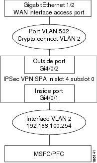
This section describes how to configure the VSPA with an access port connection to the WAN router (see Figure 3-2).
Figure 3-2 Access Port Configuration Example
Note ![]() Ethernet ports installed in a Cisco 7600 SIP-400 in the chassis cannot be configured as switch ports.
Ethernet ports installed in a Cisco 7600 SIP-400 in the chassis cannot be configured as switch ports.
Access Port Configuration Procedure
To configure an access port connection to the WAN router, perform the following task beginning in global configuration mode:
For access port configuration examples, see the "Access Port in Crypto-Connect Mode Configuration Example" section.
Verifying the Access Port Configuration
To verify an access port configuration, enter the show crypto vlan command.
Router# show crypto vlan
Interface VLAN 2 on IPSec Service Module port Gi4/0/1 connected to VLAN 502 with crypto
map set MyMap
Configuring a Routed Port
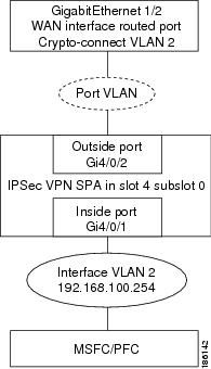
This section describes how to configure the VSPA with a routed port connection to the WAN router (see Figure 3-3).
Note ![]() When a routed port without an IP address is crypto-connected to an interface VLAN, a hidden port VLAN is created automatically. This port VLAN is not explicitly configured by the user and does not appear in the running configuration.
When a routed port without an IP address is crypto-connected to an interface VLAN, a hidden port VLAN is created automatically. This port VLAN is not explicitly configured by the user and does not appear in the running configuration.
Figure 3-3 Routed Port Configuration Example
Routed Port Configuration Guidelines
When configuring a routed port using the VSPA, follow these configuration guidelines:
•![]() When a routed port has a crypto connection, IP ACLs cannot be attached to the routed port. Instead, you can apply IP ACLs to the attached interface VLAN.
When a routed port has a crypto connection, IP ACLs cannot be attached to the routed port. Instead, you can apply IP ACLs to the attached interface VLAN.
•![]() Unlike an access port or trunk port, the routed port does not use the switchport command in its configuration.
Unlike an access port or trunk port, the routed port does not use the switchport command in its configuration.
Routed Port Configuration Procedure
To configure a routed port connection to the WAN router, perform this task beginning in global configuration mode:
For routed port configuration examples, see the "Routed Port in Crypto-Connect Mode Configuration Example" section.
Verifying a Routed Port Configuration
To verify a route port configuration, enter the show crypto vlan command. In the following example, Gi 1/2 is the crypto-connected port:
Router# show crypto vlan
Interface VLAN 2 on IPSec Service Module port Gi4/0/1 connected to Gi1/2 with crypto map
set MyMap
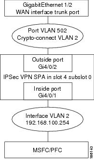
Configuring a Trunk Port

This section describes how to configure the VSPA with a trunk port connection to the WAN router (see Figure 3-4).
Figure 3-4 Trunk Port Configuration Example
Note ![]() Ethernet ports installed in a Cisco 7600 SIP-400 in the chassis cannot be configured as switch ports.
Ethernet ports installed in a Cisco 7600 SIP-400 in the chassis cannot be configured as switch ports.
Trunk Port Configuration Guidelines
When configuring a trunk port using the VSPA, follow these configuration guidelines:
•![]() When you configure a trunk port for cryptographic connection, do not use the "all VLANs allowed" default. You must explicitly specify all the desirable VLANs using the switchport trunk allowed vlan command.
When you configure a trunk port for cryptographic connection, do not use the "all VLANs allowed" default. You must explicitly specify all the desirable VLANs using the switchport trunk allowed vlan command.
•![]() Due to an incorrect startup configuration or through the default trunk port configuration, an interface VLAN might be associated with a trunk port. When you try to remove the interface VLAN from the VLAN list, you might receive an error message similar to the following:
Due to an incorrect startup configuration or through the default trunk port configuration, an interface VLAN might be associated with a trunk port. When you try to remove the interface VLAN from the VLAN list, you might receive an error message similar to the following:
Command rejected:VLAN 2 is crypto connected to V502.
To remove the interface VLAN from the VLAN list, enter the following commands:
Router# configure terminal
Router(config)# interface g1gabitethernet1/2
Router(config-if)# no switchport mode trunk
Router(config-if)# switchport trunk allowed vlan 1
Router(config-if)# switchport mode trunk
Router(config-if)# switchport trunk allowed vlan 1,502,1002-1005
Note ![]() VLANs in the VLAN list must not include any interface VLANs.
VLANs in the VLAN list must not include any interface VLANs.
•![]() To ensure that no interface VLANs are associated when you put an Ethernet port into the trunk mode, enter the following commands in the exact order given:
To ensure that no interface VLANs are associated when you put an Ethernet port into the trunk mode, enter the following commands in the exact order given:
Router# configure terminal
Router(config)# interface g1gabitethernet1/2
Router(config)# no shut
Router(config-if)# switchport
Router(config-if)# switchport trunk allowed vlan 1
Router(config-if)# switchport trunk encapsulation dot1q
Router(config-if)# switchport mode trunk
Router(config-if)# switchport trunk allowed vlan 1,502,1002-1005
Note ![]() VLANs in the VLAN list must not include any interface VLANs.
VLANs in the VLAN list must not include any interface VLANs.
•![]() A common mistake when configuring a trunk port occurs when you use the add option as follows:
A common mistake when configuring a trunk port occurs when you use the add option as follows:
Router(config-if)# switchport trunk allowed vlan add 502
If the switchport trunk allowed vlan command has not already been used, the add option does not make VLAN 502 the only allowed VLAN on the trunk port; all VLANs are still allowed after entering the command because all the VLANs are allowed by default. After you use the switchport trunk allowed vlan command to add a VLAN, you can then use the switchport trunk allowed vlan add command to add additional VLANs.
•![]() To remove unwanted VLANs from a trunk port, use the switchport trunk allowed vlan remove command.
To remove unwanted VLANs from a trunk port, use the switchport trunk allowed vlan remove command.
Trunk Port Configuration Procedure
To configure a trunk port connection to the WAN switch, perform this task beginning in global configuration mode:
For trunk port configuration examples, see the "Trunk Port in Crypto-Connect Mode Configuration Example" section.
Verifying the Trunk Port Configuration
To verify the VLANs allowed by a trunk port, enter the show interfaces trunk command. The following display shows that all VLANs are allowed:
Router# show interfaces GigabitEthernet 1/2 trunk
Port Mode Encapsulation Status Native vlan
Gi1/2 on 802.1q trunking 1
Port Vlans allowed on trunk
Gi1/2 1-4094
Port Vlans allowed and active in management domain
Gi1/2 1-4,7-8,513,1002-1005
Port Vlans in spanning tree forwarding state and not pruned
Gi1/2 1-4,7-8,513,1002-1005
Configuring VSPA Connections to WAN Interfaces
The configuration of VSPA connections to WAN interfaces is similar to the configuration of Ethernet routed interfaces.
VSPA Connections to WAN Interfaces Configuration Guidelines and Restrictions
When configuring a connection to a WAN interface using a VSPA, follow these guidelines and note these restrictions:
•![]() To configure a VSPA connection to a WAN interface, make a crypto connection from the WAN subinterface to the interface VLAN as follows:
To configure a VSPA connection to a WAN interface, make a crypto connection from the WAN subinterface to the interface VLAN as follows:
Router(config)# interface Vlan101
Router(config-if)# ip address 192.168.101.1 255.255.255.0
Router(config-if)# no mop enabled
Router(config-if)# crypto map cwan
Router(config-if)# crypto engine slot 4/0
Router(config)# interface ATM6/0/0.101 point-to-point
Router(config-subif)# pvc 0/101
Router(config-subif)# crypto connect vlan 101
•![]() You must configure a crypto connection on subinterfaces for ATM and Frame Relay.
You must configure a crypto connection on subinterfaces for ATM and Frame Relay.
•![]() For ATM, there is no SVC support, no RFC-1483 bridging, and no point-to-multipoint support.
For ATM, there is no SVC support, no RFC-1483 bridging, and no point-to-multipoint support.
•![]() For Frame Relay, there is no SVC support, no RFC-1490 bridging, and no point-to-multipoint support.
For Frame Relay, there is no SVC support, no RFC-1490 bridging, and no point-to-multipoint support.
•![]() For Point-to-Point Protocol (PPP) and Multilink PPP (MLPPP), you must make the physical interface passive for routing protocols, as follows:
For Point-to-Point Protocol (PPP) and Multilink PPP (MLPPP), you must make the physical interface passive for routing protocols, as follows:
Router(config)# router ospf 10
Router(config-router)# passive-interface multilink1
•![]() For PPP and MLP, an ip unnumbered Null0 command is automatically added to the port configuration to support IPCP negotiation. If you configure a no ip address command on the WAN port in the startup configuration, the no ip address command will be automatically removed in the running configuration so that it does not conflict with the automatic configuration.
For PPP and MLP, an ip unnumbered Null0 command is automatically added to the port configuration to support IPCP negotiation. If you configure a no ip address command on the WAN port in the startup configuration, the no ip address command will be automatically removed in the running configuration so that it does not conflict with the automatic configuration.
•![]() For PPP and MLP, there is no Bridging Control Protocol (BCP) support.
For PPP and MLP, there is no Bridging Control Protocol (BCP) support.
•![]() When enabled on an inside VLAN, OSPF will be configured in broadcast network mode by default, even when a point-to-point interface (such as T1, POS, serial, or ATM) is crypto-connected to the inside VLAN. In addition, if OSPF is configured in point-to-point network mode on the peer router (for example, a transit router with no crypto card), OSPF will not establish full adjacency. In this case, you can manually configure OSPF network point-to-point mode in the inside VLAN:
When enabled on an inside VLAN, OSPF will be configured in broadcast network mode by default, even when a point-to-point interface (such as T1, POS, serial, or ATM) is crypto-connected to the inside VLAN. In addition, if OSPF is configured in point-to-point network mode on the peer router (for example, a transit router with no crypto card), OSPF will not establish full adjacency. In this case, you can manually configure OSPF network point-to-point mode in the inside VLAN:
Router(config)# interface vlan inside-vlan
Router(config-if)# ip ospf network point-to-point
For VSPA connections to WAN interfaces configuration examples, see the "VSPA Connections to WAN Interfaces Configuration Examples" section
Displaying the VPN Running State
Use the show crypto vlan command to display the VPN running state. The following examples show the show crypto vlan command output for a variety of VSPA configurations.
In the following example, the interface VLAN belongs to the VSPA inside port:
Router# show crypto vlan
Interface VLAN 2 on IPSec Service Module port Gi4/0/1 connected to Fa8/3
In the following example, VLAN 2 is the interface VLAN and VLAN 2022 is the hidden VLAN:
Router# show crypto vlan
Interface VLAN 2 on IPSec Service Module port Gi4/0/1 connected to VLAN 2022 with crypto
map set coral2
In the following example, the interface VLAN is missing on the VSPA inside port, the VSPA is removed from the chassis, or the VSPA was moved to a different subslot:
Router# show crypto vlan
Interface VLAN 2 connected to VLAN 502 (no IPSec Service Module attached)
Configuring GRE Tunneling in Crypto-Connect Mode
In addition to choosing to configure your VPN using crypto-connect mode or VRF mode, the following additional GRE configuration options are available:
•![]() Configuring GRE Tunneling in Crypto-Connect Mode
Configuring GRE Tunneling in Crypto-Connect Mode
•![]() Configuring the GRE Takeover Criteria
Configuring the GRE Takeover Criteria
•![]() Configuring IP Multicast over a GRE Tunnel
Configuring IP Multicast over a GRE Tunnel
Configuring GRE Tunneling in Crypto-Connect Mode
Generic Routing Encapsulation (GRE) is a tunneling protocol that can encapsulate a wide variety of protocol packet types inside IP tunnels, creating a virtual point-to-point link to switches at remote points over an IP network.
Note ![]() The VSPA is able to accelerate packet processing for up to 2048 GRE tunnels per chassis. Any tunnels not taken over by the VSPA, or any tunnels in excess of 2048, are handled in platform hardware or by the route processor. The switch supports any number of GRE tunnels, but adding more VSPAs does not increase the 2048 tunnels per-chassis maximum that will be handled by VSPAs. If you configure more than 2048 tunnels per chassis, you could overload the route processor. Monitor the route processor CPU utilization when configuring more than 2048 tunnels per chassis.
The VSPA is able to accelerate packet processing for up to 2048 GRE tunnels per chassis. Any tunnels not taken over by the VSPA, or any tunnels in excess of 2048, are handled in platform hardware or by the route processor. The switch supports any number of GRE tunnels, but adding more VSPAs does not increase the 2048 tunnels per-chassis maximum that will be handled by VSPAs. If you configure more than 2048 tunnels per chassis, you could overload the route processor. Monitor the route processor CPU utilization when configuring more than 2048 tunnels per chassis.
Note ![]() If GRE encapsulation is performed by the VPN module, prefragmentation of outbound packets will be based on the IP MTU of the tunnel interface. After GRE encapsulation is performed by the VPN module, depending on the IPsec LAF (look ahead fragmentation) settings, further fragmentation may occur. The IPsec fragmentation behavior is unchanged in this release, and is based on the IPsec MTU configuration of the egress interface.
If GRE encapsulation is performed by the VPN module, prefragmentation of outbound packets will be based on the IP MTU of the tunnel interface. After GRE encapsulation is performed by the VPN module, depending on the IPsec LAF (look ahead fragmentation) settings, further fragmentation may occur. The IPsec fragmentation behavior is unchanged in this release, and is based on the IPsec MTU configuration of the egress interface.
GRE Tunneling Configuration Guidelines and Restrictions
When configuring point-to-point GRE tunneling in crypto-connect mode using the VSPA, follow these guidelines:
•![]() In a Catalyst 6500 Series switch, GRE encapsulation and decapsulation is traditionally performed by the route processor or the supervisor engine hardware. When routing indicates that encapsulated packets for a GRE tunnel will egress through an interface VLAN that is attached to a VSPA inside port, the VSPA attempts to take over the GRE tunnel interface only if the Supervisor Engine 720 is unable to process the GRE tunnel interface in hardware. If the Supervisor Engine 720 cannot process the GRE tunnel interface in hardware, the VSPA will determine if it can take over the interface. By seizing the tunnel, the VSPA takes the GRE encapsulation and decapsulation duty from the route processor. No explicit configuration changes are required to use this feature; configure GRE as you normally would. As long as routing sends the GRE-encapsulated packets over an interface VLAN, the VSPA will seize the GRE tunnel.
In a Catalyst 6500 Series switch, GRE encapsulation and decapsulation is traditionally performed by the route processor or the supervisor engine hardware. When routing indicates that encapsulated packets for a GRE tunnel will egress through an interface VLAN that is attached to a VSPA inside port, the VSPA attempts to take over the GRE tunnel interface only if the Supervisor Engine 720 is unable to process the GRE tunnel interface in hardware. If the Supervisor Engine 720 cannot process the GRE tunnel interface in hardware, the VSPA will determine if it can take over the interface. By seizing the tunnel, the VSPA takes the GRE encapsulation and decapsulation duty from the route processor. No explicit configuration changes are required to use this feature; configure GRE as you normally would. As long as routing sends the GRE-encapsulated packets over an interface VLAN, the VSPA will seize the GRE tunnel.
•![]() If the same source address is used for more than one GRE tunnel, the supervisor engine hardware will not take over the tunnel. The VSPA will take over the tunnel if it meets the criteria discussed in the previous bullet item.
If the same source address is used for more than one GRE tunnel, the supervisor engine hardware will not take over the tunnel. The VSPA will take over the tunnel if it meets the criteria discussed in the previous bullet item.
•![]() Point-to-point GRE with tunnel protection is not supported in crypto-connect mode, but DMVPN is supported.
Point-to-point GRE with tunnel protection is not supported in crypto-connect mode, but DMVPN is supported.
•![]() If routing information changes and the GRE-encapsulated packets no longer egress through an interface VLAN, the VSPA yields the GRE tunnel. After the VSPA yields the tunnel, the route processor resumes encapsulation and decapsulation, which increases CPU utilization on the route processor.
If routing information changes and the GRE-encapsulated packets no longer egress through an interface VLAN, the VSPA yields the GRE tunnel. After the VSPA yields the tunnel, the route processor resumes encapsulation and decapsulation, which increases CPU utilization on the route processor.
•![]() A delay of up to 10 seconds occurs between routing changes and the VSPA seizing the GRE tunnel.
A delay of up to 10 seconds occurs between routing changes and the VSPA seizing the GRE tunnel.
•![]() The crypto map must only be applied to the interface VLAN and not to the tunnel interface.
The crypto map must only be applied to the interface VLAN and not to the tunnel interface.
•![]() The following options are supported on the tunnel interface: ACLs, service policy, TTL, and ToS.
The following options are supported on the tunnel interface: ACLs, service policy, TTL, and ToS.
•![]() The following options are not supported on the tunnel interface: checksum enabled, sequence check enabled, tunnel key, IP security options, policy-based routing (PBR), traffic shaping (can be applied to the crypto engine configuration within the tunnel interface configuration), QoS preclassification, and NAT.
The following options are not supported on the tunnel interface: checksum enabled, sequence check enabled, tunnel key, IP security options, policy-based routing (PBR), traffic shaping (can be applied to the crypto engine configuration within the tunnel interface configuration), QoS preclassification, and NAT.
•![]() When the GRE tunnel is taken over in crypto-connect mode, any ACL configured on the interface VLAN will not be applied to packets routed to the GRE interface. The ACL will be applied to packets that do not have GRE processing.
When the GRE tunnel is taken over in crypto-connect mode, any ACL configured on the interface VLAN will not be applied to packets routed to the GRE interface. The ACL will be applied to packets that do not have GRE processing.
•![]() GRE tunneling of all non-IPv4 packets is done by the route processor even if the tunnel is seized by the VSPA.
GRE tunneling of all non-IPv4 packets is done by the route processor even if the tunnel is seized by the VSPA.
GRE Tunneling Configuration Procedure
To configure a GRE tunnel, perform this task beginning in global configuration mode:
Verifying the GRE Tunneling Configuration
To verify that the VSPA has seized the GRE tunnel, enter the show crypto vlan command:
Router# show crypto vlan
Interface VLAN 101 on IPSec Service Module port 7/1/1 connected to AT4/0/0.101
Tunnel101 is accelerated via IPSec SM in subslot 7/1
Router#
For complete configuration information about GRE tunneling, refer to this URL:
http://www.cisco.com/en/US/docs/ios/12_0s/feature/guide/12s_tos.html
For GRE tunneling configuration examples, see the "GRE Tunneling in Crypto-Connect Mode Configuration Example" section.
Configuring the GRE Takeover Criteria
You can configure the takeover criteria for Generic Routing Encapsulation (GRE) processing by using the crypto engine gre supervisor or crypto engine gre vpnblade commands. These two commands allow you to specify whether the GRE processing should be done by the supervisor engine hardware or the route processor or the VSPA.
To configure a switch to process GRE using the supervisor engine hardware or the route processor (RP), use the crypto engine gre supervisor command. When this command is specified, GRE processing by the supervisor engine hardware takes precedence over processing by the route processor (unless the tunnels are from duplicate sources); the RP only takes over GRE processing if the supervisor engine hardware cannot do the processing. If this command is configured, duplicate source GREs will be processed by the route processor.
To configure a switch to process GRE using the VSPA, use the crypto engine gre vpnblade command. If the VSPA cannot take over the GRE processing, the GRE processing will be handled either by supervisor engine hardware (which has precedence) or the route processor.
Both of these commands can be configured globally or at an individual tunnel.
Individual tunnel configuration takes precedence over the global configuration. For example, when the crypto engine gre supervisor command is configured at the global configuration level, the command will apply to all tunnels except those tunnels that have been configured individually using either a crypto engine gre supervisor command or a crypto engine gre vpnblade command.
At any time, only one of the two commands (crypto engine gre supervisor or crypto engine gre vpnblade) can be configured globally or individually at a tunnel. If either command is already configured, configuring the second command will overwrite the first command, and only the configuration applied by the second command will be used.
GRE Takeover Configuration Guidelines and Restrictions
When configuring GRE takeover on the VSPA, follow these guidelines and restrictions:
•![]() For a GRE tunnel to be taken over by the VSPA, it must first satisfy the following criteria:
For a GRE tunnel to be taken over by the VSPA, it must first satisfy the following criteria:
–![]() The GRE tunnel interface must be up.
The GRE tunnel interface must be up.
–![]() The route to the tunnel destination must go through the VSPA.
The route to the tunnel destination must go through the VSPA.
–![]() The Address Resolution Protocol (ARP) entry for the next hop must exist.
The Address Resolution Protocol (ARP) entry for the next hop must exist.
–![]() The tunnel mode must be GRE.
The tunnel mode must be GRE.
–![]() The only supported options are tunnel ttl and tunnel tos. If any of the following command options are configured, then the tunnel will not be taken over:
The only supported options are tunnel ttl and tunnel tos. If any of the following command options are configured, then the tunnel will not be taken over:
•![]() tunnel key
tunnel key
•![]() tunnel sequence-datagrams
tunnel sequence-datagrams
•![]() tunnel checksum
tunnel checksum
All other options configured are ignored.
•![]() If the GRE tunnels have the same source and destination addresses, then the VSPA will, at most, take over only one of them, and the determination of which specific tunnel is taken over is random.
If the GRE tunnels have the same source and destination addresses, then the VSPA will, at most, take over only one of them, and the determination of which specific tunnel is taken over is random.
•![]() The VSPA will not take over GRE processing if any of the following features are configured on the tunnel interface:
The VSPA will not take over GRE processing if any of the following features are configured on the tunnel interface:
–![]() DMVPN
DMVPN
–![]() NAT
NAT
•![]() In crypto-connect mode, the VSPA will not take over GRE processing when the interface VLAN has no crypto map attached. The crypto map must be applied to the interface VLAN and not to the tunnel interface.
In crypto-connect mode, the VSPA will not take over GRE processing when the interface VLAN has no crypto map attached. The crypto map must be applied to the interface VLAN and not to the tunnel interface.
•![]() If the VSPA cannot take over the GRE processing, the GRE processing will be handled either by the supervisor engine hardware (which has precedence) or the route processor.
If the VSPA cannot take over the GRE processing, the GRE processing will be handled either by the supervisor engine hardware (which has precedence) or the route processor.
•![]() When neither the crypto engine gre supervisor command nor the crypto engine gre vpnblade command is specified globally or individually for a tunnel, the VSPA will only attempt to take over GRE processing if the following conditions apply:
When neither the crypto engine gre supervisor command nor the crypto engine gre vpnblade command is specified globally or individually for a tunnel, the VSPA will only attempt to take over GRE processing if the following conditions apply:
–![]() The supervisor engine hardware does not take over GRE processing.
The supervisor engine hardware does not take over GRE processing.
–![]() Protocol Independent Multicast (PIM) is configured on the tunnel.
Protocol Independent Multicast (PIM) is configured on the tunnel.
–![]() Multiple tunnels share the same tunnel source interface and more than one tunnel is up. (If only one tunnel is up, the supervisor engine hardware can still perform the GRE processing.)
Multiple tunnels share the same tunnel source interface and more than one tunnel is up. (If only one tunnel is up, the supervisor engine hardware can still perform the GRE processing.)
•![]() When a new configuration file is copied to the running configuration, the new configuration will overwrite the old configuration for the crypto engine gre vpnblade and crypto engine gre supervisor commands. If the new configuration does not specify a GRE takeover criteria globally or for an individual tunnel, the existing old configuration will be used.
When a new configuration file is copied to the running configuration, the new configuration will overwrite the old configuration for the crypto engine gre vpnblade and crypto engine gre supervisor commands. If the new configuration does not specify a GRE takeover criteria globally or for an individual tunnel, the existing old configuration will be used.
•![]() GRE keepalives are not supported if crypto engine gre vpnblade is configured.
GRE keepalives are not supported if crypto engine gre vpnblade is configured.
Configuring the GRE Takeover Criteria Globally
To configure the GRE takeover criteria globally (so that it affects all tunnels except those tunnels that have been configured individually using either a crypto engine gre supervisor command or a crypto engine gre vpnblade command), perform this task beginning in global configuration mode:
Configuring the GRE Takeover Criteria at an Individual Tunnel
To configure the GRE takeover criteria at an individual tunnel (so that it affects only a specific tunnel), perform this task beginning in global configuration mode:
For GRE takeover criteria configuration examples, see the "GRE Takeover Criteria Configuration Examples" section.
Configuring IP Multicast over a GRE Tunnel
IP multicast is a bandwidth-conserving technology that reduces traffic by simultaneously delivering a single stream of information to multiple recipients. GRE is a tunneling protocol developed by Cisco and commonly used with IPsec that encapsulates a wide variety of protocol packet types inside IP tunnels, creating a virtual point-to-point link to Cisco routers at remote points over an IP network.
In some network scenarios, you might want to configure your network to use GRE tunnels to send Protocol Independent Multicast (PIM) and multicast traffic between routers. Typically, this occurs when the multicast source and receiver are separated by an IP cloud that is not configured for IP multicast routing. In such network scenarios, configuring a tunnel across an IP cloud with PIM-enabled transports multicast packets toward the receiver. The configuration of IP multicast over a GRE tunnel using the VSPA involves these key steps:
•![]() Configuring multicast globally
Configuring multicast globally
•![]() Configuring PIM at the tunnel interfaces
Configuring PIM at the tunnel interfaces
IP Multicast over a GRE Tunnel Configuration Guidelines and Restrictions
When configuring IP multicast over a GRE tunnel, follow these guidelines:
•![]() If PIM is configured, and the GRE tunnel interface satisfies the rest of the tunnel takeover criteria, the GRE processing of the multicast packets will be taken over by the VSPA.
If PIM is configured, and the GRE tunnel interface satisfies the rest of the tunnel takeover criteria, the GRE processing of the multicast packets will be taken over by the VSPA.
•![]() GRE processing of IP multicast packets will be taken over by the VSPA if the GRE tunnel interface satisfies the following tunnel takeover criteria:
GRE processing of IP multicast packets will be taken over by the VSPA if the GRE tunnel interface satisfies the following tunnel takeover criteria:
–![]() The tunnel is up.
The tunnel is up.
–![]() There are no other tunnels with the same source destination pair.
There are no other tunnels with the same source destination pair.
–![]() The tunnel is not a multipoint GRE (mGRE) tunnel.
The tunnel is not a multipoint GRE (mGRE) tunnel.
–![]() PIM is configured on the tunnel.
PIM is configured on the tunnel.
–![]() None of the following features are configured on the tunnel: tunnel key, tunnel sequence-datagrams, tunnel checksum, tunnel udlr address-resolution, tunnel udlr receive-only, tunnel udlr send-only, ip proxy-mobile tunnel reverse, or NAT. If any of these options are specified, the VSPA will not seize the GRE tunnel.
None of the following features are configured on the tunnel: tunnel key, tunnel sequence-datagrams, tunnel checksum, tunnel udlr address-resolution, tunnel udlr receive-only, tunnel udlr send-only, ip proxy-mobile tunnel reverse, or NAT. If any of these options are specified, the VSPA will not seize the GRE tunnel.
•![]() When a tunnel is configured for multicast traffic, the crypto engine gre supervisor command should not be applied to the tunnel.
When a tunnel is configured for multicast traffic, the crypto engine gre supervisor command should not be applied to the tunnel.
Configuring IP Multicast Globally
You must enable IP multicast routing globally before you can enable PIM on the router interfaces.
To enable IP multicast routing globally, use the ip multicast-routing command.
Configuring PIM at the Tunnel Interfaces
You must enable PIM on all participating router interfaces before IP multicast will function.
To enable PIM, use the ip pim command as follows:
Router(config-if)# ip pim {dense-mode | sparse-mode | sparse-dense-mode}
dense-mode enables dense mode of operation.
sparse-mode enables sparse mode of operation.
sparse-dense-mode enables the interface in either sparse mode or dense mode of operation, depending on which mode the multicast group operates in.
For IP multicast over GRE tunnels configuration examples, see the "IP Multicast over a GRE Tunnel Configuration Example" section.
Verifying the IP Multicast over a GRE Tunnel Configuration
To verify the IP multicast over a GRE tunnel configuration, enter the show crypto vlan and show ip mroute commands.
To verify that the tunnel has been taken over by the VSPA, enter the show crypto vlan command:
Router# show crypto vlan
Interface VLAN 100 on IPSec Service Module port Gi7/0/1 connected to Po1 with crypto map
set map_t3
Tunnel15 is accelerated via IPSec SM in subslot 7/0
To verify that the IP multicast traffic is hardware-switched, enter the show ip mroute command and look for the H flag:
Router# show ip mroute 230.1.1.5
IP Multicast Routing Table
Flags: D - Dense, S - Sparse, B - Bidir Group, s - SSM Group, C - Connected,
L - Local, P - Pruned, R - RP-bit set, F - Register flag,
T - SPT-bit set, J - Join SPT, M - MSDP created entry,
X - Proxy Join Timer Running, A - Candidate for MSDP Advertisement,
U - URD, I - Received Source Specific Host Report, Z - Multicast Tunnel
Y - Joined MDT-data group, y - Sending to MDT-data group
Outgoing interface flags: H - Hardware switched, A - Assert winner
Timers: Uptime/Expires
Interface state: Interface, Next-Hop or VCD, State/Mode
(*, 230.1.1.5), 01:23:45/00:03:16, RP 15.15.1.1, flags: SJC
Incoming interface: Null, RPF nbr 0.0.0.0
Outgoing interface list:
Tunnel15, Forward/Sparse-Dense, 00:25:47/00:03:16
(120.1.0.3, 230.1.1.5), 01:23:46/00:03:25, flags: T
Incoming interface: GigabitEthernet8/1, RPF nbr 0.0.0.0, RPF-MFD
Outgoing interface list:
Tunnel15, Forward/Sparse-Dense, 00:25:47/00:03:16, H
For IP multicast over GRE tunnels configuration examples, see the "IP Multicast over a GRE Tunnel Configuration Example" section.
Configuration Examples
This section provides examples of the following configurations:
•![]() Access Port in Crypto-Connect Mode Configuration Example
Access Port in Crypto-Connect Mode Configuration Example
•![]() Routed Port in Crypto-Connect Mode Configuration Example
Routed Port in Crypto-Connect Mode Configuration Example
•![]() Trunk Port in Crypto-Connect Mode Configuration Example
Trunk Port in Crypto-Connect Mode Configuration Example
•![]() VSPA Connections to WAN Interfaces Configuration Examples
VSPA Connections to WAN Interfaces Configuration Examples
•![]() GRE Tunneling in Crypto-Connect Mode Configuration Example
GRE Tunneling in Crypto-Connect Mode Configuration Example
•![]() GRE Takeover Criteria Configuration Examples
GRE Takeover Criteria Configuration Examples
•![]() IP Multicast over a GRE Tunnel Configuration Example
IP Multicast over a GRE Tunnel Configuration Example
Access Port in Crypto-Connect Mode Configuration Example
This section provides an example of the access port configuration with switch 1 shown in Figure 3-2:
Switch 1 (Access Port)
!
hostname router-1
!
vlan 2,502
!
crypto isakmp policy 1
encr 3des
authentication pre-share
crypto isakmp key 12345 address 11.0.0.1
!
!
crypto ipsec transform-set proposal1 esp-3des esp-md5-hmac
!
crypto map testtag 10 ipsec-isakmp
set peer 11.0.0.1
set transform-set proposal1
match address 101
!
!
interface GigabitEthernet1/1
!switch inside port
ip address 13.0.0.1 255.255.255.0
!
interface GigabitEthernet1/2
!switch outside port
switchport
switchport access vlan 502
switchport mode access
!
interface GigabitEthernet4/0/1
!IPSec VPN Module inside port
switchport
switchport trunk encapsulation dot1q
switchport trunk allowed vlan 1,2,1002-1005
switchport mode trunk
mtu 9216
flowcontrol receive on
flowcontrol send off
spanning-tree portfast trunk
!
interface GigabitEthernet4/0/2
!IPSec VPN Module outside port
switchport
switchport trunk encapsulation dot1q
switchport trunk allowed vlan 1,502,1002-1005
switchport mode trunk
mtu 9216
flowcontrol receive on
flowcontrol send off
spanning-tree portfast trunk
interface Vlan2
!interface vlan
ip address 11.0.0.2 255.255.255.0
crypto map testtag
crypto engine slot 4/0
!
interface Vlan502
!port vlan
no ip address
crypto connect vlan 2
!
ip classless
ip route 12.0.0.0 255.0.0.0 11.0.0.1
!
access-list 101 permit ip host 13.0.0.2 host 12.0.0.2
!
end
Switch 2 (Access Port)
!
hostname router-2
!
vlan 2,502
!
crypto isakmp policy 1
encr 3des
authentication pre-share
crypto isakmp key 12345 address 11.0.0.2
!
!
crypto ipsec transform-set proposal1 esp-3des esp-md5-hmac
!
crypto map testtag 10 ipsec-isakmp
set peer 11.0.0.2
set transform-set proposal1
match address 101
!
!
interface GigabitEthernet1/1
!switch inside port
ip address 12.0.0.1 255.255.255.0
!
interface GigabitEthernet1/2
!switch outside port
switchport
switchport access vlan 502
switchport mode access
!
interface GigabitEthernet4/0/1
!IPSec VPN Module inside port
switchport
switchport trunk encapsulation dot1q
switchport trunk allowed vlan 1,2,1002-1005
switchport mode trunk
mtu 9216
flowcontrol receive on
flowcontrol send off
spanning-tree portfast trunk
!
interface GigabitEthernet4/0/2
!IPSec VPN Module outside port
switchport
switchport trunk encapsulation dot1q
switchport trunk allowed vlan 1,502,1002-1005
switchport mode trunk
mtu 9216
flowcontrol receive on
flowcontrol send off
spanning-tree portfast trunk
!
interface Vlan2
!interface vlan
ip address 11.0.0.1 255.255.255.0
crypto map testtag
crypto engine slot 4/0
!
interface Vlan502
!port vlan
no ip address
crypto connect vlan 2
!
ip classless
ip route 13.0.0.0 255.0.0.0 11.0.0.2
!
access-list 101 permit ip host 12.0.0.2 host 13.0.0.2
!
end
Routed Port in Crypto-Connect Mode Configuration Example
This section provides an example of the routed port configuration with switch 1 shown in Figure 3-3:
Switch 1 (Routed Port)
!
hostname router-1
!
vlan 2
!
crypto isakmp policy 1
encr 3des
authentication pre-share
crypto isakmp key 12345 address 11.0.0.2
!
!
crypto ipsec transform-set proposal1 esp-3des esp-md5-hmac
!
crypto map testtag 10 ipsec-isakmp
set peer 11.0.0.2
set transform-set proposal1
match address 101
!
!
interface GigabitEthernet1/1
!switch inside port
ip address 12.0.0.1 255.255.255.0
!
interface GigabitEthernet1/2
!switch outside port
no ip address
crypto connect vlan 2
!
interface GigabitEthernet4/0/1
!IPSec VPN Module inside port
switchport
switchport trunk encapsulation dot1q
switchport trunk allowed vlan 1,2,1002-1005
switchport mode trunk
mtu 9216
flowcontrol receive on
flowcontrol send off
spanning-tree portfast trunk
!
interface GigabitEthernet4/0/2
!IPSec VPN Module outside port
switchport
switchport trunk encapsulation dot1q
switchport trunk allowed vlan 1,1002-1005
switchport mode trunk
mtu 9216
flowcontrol receive on
flowcontrol send off
spanning-tree portfast trunk
!
interface Vlan2
!interface vlan
ip address 11.0.0.1 255.255.255.0
no mop enabled
crypto map testtag
crypto engine slot 4/0
!
ip classless
ip route 13.0.0.0 255.0.0.0 11.0.0.2
!
access-list 101 permit ip host 12.0.0.2 host 13.0.0.2
!
end
Switch 2 (Routed Port)
!
hostname router-2
!
vlan 2
!
!
crypto isakmp policy 1
encr 3des
authentication pre-share
crypto isakmp key 12345 address 11.0.0.1
!
!
crypto ipsec transform-set proposal1 esp-3des esp-md5-hmac
!
crypto map testtag 10 ipsec-isakmp
set peer 11.0.0.1
set transform-set proposal1
match address 101
!
!
interface GigabitEthernet1/1
!switch inside port
ip address 13.0.0.1 255.255.255.0
!
interface GigabitEthernet1/2
!switch outside port
no ip address
crypto connect vlan 2
!
interface GigabitEthernet4/0/1
!IPSec VPN Module inside port
switchport
switchport trunk encapsulation dot1q
switchport trunk allowed vlan 1,2,1002-1005
switchport mode trunk
mtu 9216
flowcontrol receive on
flowcontrol send off
spanning-tree portfast trunk
!
interface GigabitEthernet4/0/2
!IPSec VPN Module outside port
switchport
switchport trunk encapsulation dot1q
switchport trunk allowed vlan 1,1002-1005
switchport mode trunk
mtu 9216
flowcontrol receive on
flowcontrol send off
spanning-tree portfast trunk
!
interface Vlan2
!interface vlan
ip address 11.0.0.2 255.255.255.0
no mop enabled
crypto map testtag
crypto engine slot 4/0
!
ip classless
ip route 12.0.0.0 255.0.0.0 11.0.0.1
!
access-list 101 permit ip host 13.0.0.2 host 12.0.0.2
!
end
Trunk Port in Crypto-Connect Mode Configuration Example
This section provides an example of the trunk port configuration with switch 1 shown in Figure 3-4:
Switch 1 (Trunk Port)
!
hostname router-1
!
vlan 2,502
!
crypto isakmp policy 1
encr 3des
authentication pre-share
crypto isakmp key 12345 address 11.0.0.2
!
!
crypto ipsec transform-set proposal1 esp-3des esp-md5-hmac
!
crypto map testtag 10 ipsec-isakmp
set peer 11.0.0.2
set transform-set proposal1
match address 101
!
!
interface GigabitEthernet1/1
!switch inside port
ip address 12.0.0.1 255.255.255.0
!
interface GigabitEthernet1/2
!switch outside port
switchport
switchport trunk encapsulation dot1q
switchport trunk allowed vlan 502
switchport mode trunk
!
interface GigabitEthernet4/0/1
!IPSec VPN Module inside port
switchport
switchport trunk encapsulation dot1q
switchport trunk allowed vlan 1,2,1002-1005
switchport mode trunk
mtu 9216
flowcontrol receive on
flowcontrol send off
spanning-tree portfast trunk
!
interface GigabitEthernet4/0/2
!IPSec VPN Module outside port
switchport
switchport trunk encapsulation dot1q
switchport trunk allowed vlan 1,502,1002-1005
switchport mode trunk
mtu 9216
flowcontrol receive on
flowcontrol send off
spanning-tree portfast trunk
!
interface Vlan2
!interface vlan
ip address 11.0.0.1 255.255.255.0
crypto map testtag
crypto engine slot 4/0
!
interface Vlan 502
!port vlan
no ip address
crypto connect vlan 2
!
ip classless
ip route 13.0.0.0 255.0.0.0 11.0.0.2
!
access-list 101 permit ip host 12.0.0.2 host 13.0.0.2
!
end
Switch 2 (Trunk Port)
!
hostname router-2
!
vlan 2,502
!
crypto isakmp policy 1
encr 3des
authentication pre-share
crypto isakmp key 12345 address 11.0.0.1
!
!
crypto ipsec transform-set proposal1 esp-3des esp-md5-hmac
!
crypto map testtag 10 ipsec-isakmp
set peer 11.0.0.1
set transform-set proposal1
match address 101
!
!
interface GigabitEthernet1/1
!switch inside port
ip address 13.0.0.1 255.255.255.0
!
interface GigabitEthernet1/2
!switch outside port
switchport
switchport trunk encapsulation dot1q
switchport trunk allowed vlan 502
switchport mode trunk
!
interface GigabitEthernet4/0/1
!IPSec VPN Module inside port
switchport
switchport trunk encapsulation dot1q
switchport trunk allowed vlan 1,2,1002-1005
switchport mode trunk
mtu 9216
flowcontrol receive on
flowcontrol send off
spanning-tree portfast trunk
!
interface GigabitEthernet4/0/2
!IPSec VPN Module outside port
switchport
switchport trunk encapsulation dot1q
switchport trunk allowed vlan 1,502,1002-1005
switchport mode trunk
mtu 9216
flowcontrol receive on
flowcontrol send off
spanning-tree portfast trunk
interface Vlan2
!interface vlan
ip address 11.0.0.2 255.255.255.0
crypto map testtag
crypto engine slot 4/0
!
interface Vlan502
!port vlan
no ip address
crypto connect vlan 2
!
ip classless
ip route 12.0.0.0 255.0.0.0 11.0.0.1
!
access-list 101 permit ip host 13.0.0.2 host 12.0.0.2
!
end
VSPA Connections to WAN Interfaces Configuration Examples
The following are configuration examples of VSPA connections to WAN interfaces:
•![]() VSPA Connection to an ATM Port Adapter Configuration Example
VSPA Connection to an ATM Port Adapter Configuration Example
•![]() VSPA Connection to a POS Port Adapter Configuration Example
VSPA Connection to a POS Port Adapter Configuration Example
•![]() VSPA Connection to a Serial Port Adapter Configuration Example
VSPA Connection to a Serial Port Adapter Configuration Example
VSPA Connection to an ATM Port Adapter Configuration Example
The following example shows the configuration of a VSPA connection to an ATM port adapter:
!
hostname router-1
!
crypto isakmp policy 1
encr 3des
hash md5
authentication pre-share
crypto isakmp key 12345 address 0.0.0.0 0.0.0.0
!
!
crypto ipsec transform-set proposal esp-3des esp-sha-hmac
!
crypto map testtag_1 10 ipsec-isakmp
set peer 11.0.0.2
set transform-set proposal
match address acl_1
!
interface GigabitEthernet1/1
ip address 12.0.0.2 255.255.255.0
!
interface ATM2/0/0
no ip address
atm clock INTERNAL
no atm enable-ilmi-trap
no atm ilmi-keepalive
!
interface ATM2/0/0.1 point-to-point
atm pvc 20 0 20 aal5snap
no atm enable-ilmi-trap
crypto connect vlan 2
!
interface GigabitEthernet4/0/1
!IPSec VPN Module inside port
switchport
switchport trunk encapsulation dot1q
switchport trunk allowed vlan 1,2,1002-1005
switchport mode trunk
mtu 9216
flowcontrol receive on
flowcontrol send off
spanning-tree portfast trunk
!
interface GigabitEthernet4/0/2
!IPSec VPN Module outside port
switchport
switchport trunk encapsulation dot1q
switchport trunk allowed vlan 1,1002-1005
switchport mode trunk
mtu 9216
flowcontrol receive on
flowcontrol send off
spanning-tree portfast trunk
!
interface Vlan2
ip address 11.0.0.1 255.255.255.0
crypto map testtag_1
crypto engine slot 4/0
!
ip classless
ip route 13.0.0.1 255.255.255.255 11.0.0.2
!
ip access-list extended acl_1
permit ip host 12.0.0.1 host 13.0.0.1
!
VSPA Connection to a POS Port Adapter Configuration Example
The following example shows the configuration of a VSPA connection to a POS port adapter:
!
hostname router-1
!
crypto isakmp policy 1
encr 3des
hash md5
authentication pre-share
crypto isakmp key 12345 address 0.0.0.0 0.0.0.0
!
!
crypto ipsec transform-set proposal esp-3des esp-sha-hmac
!
crypto map testtag_1 10 ipsec-isakmp
set peer 11.0.0.2
set transform-set proposal
match address acl_1
!
interface GigabitEthernet1/1
!switch inside port
ip address 12.0.0.2 255.255.255.0
!
interface POS2/0/0
no ip address
encapsulation frame-relay
clock source internal
!
interface POS2/0/0.1 point-to-point
frame-relay interface-dlci 16
crypto connect vlan 2
!
interface GigabitEthernet4/0/1
!IPSec VPN Module inside port
switchport
switchport trunk encapsulation dot1q
switchport trunk allowed vlan 1,2,1002-1005
switchport mode trunk
mtu 9216
flowcontrol receive on
flowcontrol send off
spanning-tree portfast trunk
!
interface GigabitEthernet4/0/2
!IPSec VPN Module outside port
switchport
switchport trunk encapsulation dot1q
switchport trunk allowed vlan 1,1002-1005
switchport mode trunk
mtu 9216
flowcontrol receive on
flowcontrol send off
spanning-tree portfast trunk
!
interface Vlan2
ip address 11.0.0.1 255.255.255.0
crypto map testtag_1
crypto engine slot 4/0
!
ip classless
ip route 13.0.0.1 255.255.255.255 11.0.0.2
!
ip access-list extended acl_1
permit ip host 12.0.0.1 host 13.0.0.1
VSPA Connection to a Serial Port Adapter Configuration Example
The following example shows the configuration of a VSPA connection to a serial port adapter:
!
hostname router-1
!
controller T3 2/1/0
t1 1 channel-group 0 timeslots 1
t1 2 channel-group 0 timeslots 1
t1 3 channel-group 0 timeslots 1
t1 4 channel-group 0 timeslots 1
t1 5 channel-group 0 timeslots 1
t1 6 channel-group 0 timeslots 1
t1 7 channel-group 0 timeslots 1
t1 8 channel-group 0 timeslots 1
t1 9 channel-group 0 timeslots 1
t1 10 channel-group 0 timeslots 1
t1 11 channel-group 0 timeslots 1
t1 12 channel-group 0 timeslots 1
t1 13 channel-group 0 timeslots 1
t1 14 channel-group 0 timeslots 1
t1 15 channel-group 0 timeslots 1
t1 16 channel-group 0 timeslots 1
t1 17 channel-group 0 timeslots 1
t1 18 channel-group 0 timeslots 1
t1 19 channel-group 0 timeslots 1
t1 20 channel-group 0 timeslots 1
t1 21 channel-group 0 timeslots 1
t1 22 channel-group 0 timeslots 1
t1 23 channel-group 0 timeslots 1
t1 24 channel-group 0 timeslots 1
t1 25 channel-group 0 timeslots 1
t1 26 channel-group 0 timeslots 1
t1 27 channel-group 0 timeslots 1
t1 28 channel-group 0 timeslots 1
!
crypto isakmp policy 1
encr 3des
hash md5
authentication pre-share
crypto isakmp key 12345 address 0.0.0.0 0.0.0.0
!
!
crypto ipsec transform-set proposal esp-3des esp-sha-hmac
!
crypto map testtag_1 10 ipsec-isakmp
set peer 11.0.0.2
set transform-set proposal
match address acl_1
!
interface GigabitEthernet1/1
!switch inside port
ip address 12.0.0.2 255.255.255.0
!
interface Serial2/1/0/1:0
ip unnumbered Null0
encapsulation ppp
no fair-queue
no cdp enable
crypto connect vlan 2
!
!
interface GigabitEthernet4/0/1
!IPSec VPN Module inside port
switchport
switchport trunk encapsulation dot1q
switchport trunk allowed vlan 1,2,1002-1005
switchport mode trunk
mtu 9216
flowcontrol receive on
flowcontrol send off
spanning-tree portfast trunk
!
interface GigabitEthernet4/0/2
!IPSec VPN Module outside port
switchport
switchport trunk encapsulation dot1q
switchport trunk allowed vlan 1,1002-1005
switchport mode trunk
mtu 9216
flowcontrol receive on
flowcontrol send off
spanning-tree portfast trunk
!
interface Vlan2
ip address 11.0.0.1 255.255.255.0
crypto map testtag_1
crypto engine slot 4/0
!
ip classless
ip route 13.0.0.1 255.255.255.255 11.0.0.2
!
ip access-list extended acl_1
permit ip host 12.0.0.1 host 13.0.0.1
GRE Tunneling in Crypto-Connect Mode Configuration Example
This section provides an example of GRE tunneling configurations.
Switch 1 (GRE Tunneling)
The following example shows the configuration of GRE tunneling for switch 1:
!
hostname router-1
!
vlan 2,502
!
crypto isakmp policy 1
encr 3des
authentication pre-share
crypto isakmp key 12345 address 11.0.0.2
!
!
crypto ipsec transform-set proposal1 ah-md5-hmac
!
crypto map testtag 10 ipsec-isakmp
set peer 11.0.0.2
set transform-set proposal1
match address 101
!
!
!
!
interface Tunnel1
ip address 1.0.0.1 255.255.255.0
tunnel source Vlan2
tunnel destination 11.0.0.2
!
interface GigabitEthernet1/1
!switch inside port
ip address 12.0.0.1 255.255.255.0
!
interface GigabitEthernet1/2
!switch outside port
switchport
switchport access vlan 502
switchport mode access
!
interface GigabitEthernet4/0/1
!IPSec VPN Module inside port
switchport
switchport trunk encapsulation dot1q
switchport trunk allowed vlan 1,2,1002-1005
switchport mode trunk
mtu 9216
flowcontrol receive on
flowcontrol send off
spanning-tree portfast trunk
!
interface GigabitEthernet4/0/2
!IPSec VPN Module outside port
switchport
switchport trunk encapsulation dot1q
switchport trunk allowed vlan 1,502,1002-1005
switchport mode trunk
mtu 9216
flowcontrol receive on
flowcontrol send off
spanning-tree portfast trunk
!
interface Vlan2
ip address 11.0.0.1 255.255.255.0
no mop enabled
crypto map testtag
crypto engine slot 4/0
!
interface Vlan502
no ip address
crypto connect vlan 2
!
!
ip classless
ip route 13.0.0.0 255.0.0.0 Tunnel1
!
!
access-list 101 permit gre host 11.0.0.1 host 11.0.0.2
!
Switch 2 (GRE Tunneling)
!
hostname router-2
!
vlan 2,502
!
crypto isakmp policy 1
encr 3des
authentication pre-share
crypto isakmp key 12345 address 11.0.0.1
!
!
crypto ipsec transform-set proposal1 ah-md5-hmac
!
crypto map testtag 10 ipsec-isakmp
set peer 11.0.0.1
set transform-set proposal1
match address 101
!
!
!
!
interface Tunnel1
ip address 1.0.0.2 255.255.255.0
tunnel source Vlan2
tunnel destination 11.0.0.1
!
interface GigabitEthernet1/1
!switch inside port
ip address 13.0.0.1 255.255.255.0
!
interface GigabitEthernet1/2
!switch outside port
switchport
switchport access vlan 502
switchport mode access
!
interface GigabitEthernet4/0/1
!IPSec VPN Module inside port
switchport
switchport trunk encapsulation dot1q
switchport trunk allowed vlan 1,2,1002-1005
switchport mode trunk
mtu 9216
flowcontrol receive on
flowcontrol send off
spanning-tree portfast trunk
!
interface GigabitEthernet4/0/2
!IPSec VPN Module outside port
switchport
switchport trunk encapsulation dot1q
switchport trunk allowed vlan 1,502,1002-1005
switchport mode trunk
mtu 9216
flowcontrol receive on
flowcontrol send off
spanning-tree portfast trunk
!
interface Vlan2
ip address 11.0.0.2 255.255.255.0
no mop enabled
crypto map testtag
crypto engine slot 4/0
!
interface Vlan502
no ip address
crypto connect vlan 2
!
ip classless
ip route 12.0.0.0 255.0.0.0 Tunnel1
!
access-list 101 permit gre host 11.0.0.2 host 11.0.0.1
!
GRE Takeover Criteria Configuration Examples
The following examples show how to configure the GRE takeover criteria:
•![]() GRE Takeover Criteria Global Configuration Example
GRE Takeover Criteria Global Configuration Example
•![]() GRE Takeover Criteria Tunnel Configuration Example
GRE Takeover Criteria Tunnel Configuration Example
•![]() GRE Takeover Verification Example
GRE Takeover Verification Example
GRE Takeover Criteria Global Configuration Example
The following example shows that the GRE takeover criteria has been set globally and the supervisor engine hardware or RP always does the GRE processing:
Router(config)# crypto engine gre supervisor
GRE Takeover Criteria Tunnel Configuration Example
The following example shows that the GRE takeover criteria has been set individually for tunnel interface 3 and the VSPA always does the GRE processing for this tunnel:
Router(config)# interface tunnel 3
Router(config-if)# crypto engine gre vpnblade
GRE Takeover Verification Example
The following example shows how to verify that the tunnel has been taken over by the VSPA:
Router(config)# show crypto vlan 100
Interface VLAN 100 on IPSec Service Module port GigabitEthernet4/0/1 connected to POS8/0/0
with crypto map set MAP_TO_R2
Tunnel1 is accelerated via IPSec SM in subslot 4/0
The following example shows that the tunnel has not been taken over by the VSPA:
Router(config)# show crypto vlan 100
Interface VLAN 100 on IPSec Service Module port GigabitEthernet4/0/1 connected to POS8/0/0
with crypto map set MAP_TO_R2
IP Multicast over a GRE Tunnel Configuration Example
The following example shows how to configure IP multicast over GRE:
hostname router-1
!
vlan 2-1001
ip multicast-routing
!
!
crypto isakmp policy 1
encr 3des
hash md5
authentication pre-share
crypto isakmp key 12345 address 0.0.0.0 0.0.0.0
!
!
crypto ipsec transform-set proposal esp-3des
!
!
crypto map cm_spoke1_1 10 ipsec-isakmp
set peer 11.1.1.1
set transform-set proposal
match address spoke1_acl_1
!
!
interface Tunnel1
ip address 20.1.1.1 255.255.255.0
ip mtu 9216
ip pim sparse-mode
ip hold-time eigrp 1 3600
tunnel source 1.0.1.1
tunnel destination 11.1.1.1
crypto engine slot 4/0
!
interface GigabitEthernet1/1
!switch inside port
mtu 9216
ip address 50.1.1.1 255.0.0.0
ip pim sparse-mode
!
interface GigabitEthernet1/2
!switch outside port
switchport
switchport trunk encapsulation dot1q
switchport trunk allowed vlan 1,252,1002-1005
switchport mode trunk
mtu 9216
!
interface GigabitEthernet4/0/1
!IPSec VPN Module inside port
switchport
switchport trunk encapsulation dot1q
switchport trunk allowed vlan 1,2,1002-1005
switchport mode trunk
mtu 9216
flowcontrol receive on
flowcontrol send off
spanning-tree portfast trunk
!
interface GigabitEthernet4/0/2
!IPSec VPN Module outside port
switchport
switchport trunk encapsulation dot1q
switchport trunk allowed vlan 1,252,1002-1005
switchport mode trunk
mtu 9216
flowcontrol receive on
flowcontrol send off
spanning-tree portfast trunk
!
interface Vlan2
mtu 9216
ip address 1.0.1.1 255.255.255.0
crypto map cm_spoke1_1
crypto engine slot 4/0
!
interface Vlan252
mtu 9216
no ip address
crypto connect vlan 2
!
router eigrp 1
network 20.1.1.0 0.0.0.255
network 50.1.1.0 0.0.0.255
no auto-summary
no eigrp log-neighbor-changes
!
ip classless
ip route 11.1.1.0 255.255.255.0 1.0.1.2
!
ip pim bidir-enable
ip pim rp-address 50.1.1.1
!
ip access-list extended spoke1_acl_1
permit gre host 1.0.1.1 host 11.1.1.1
!
 Feedback