- Title and copyright: PA-2FEISL 100BASE-T FastEthernet/ISL Port Adapter Installation and Configuration
- Preface: PA-2FEISL 100BASE-T FastEthernet/ISL Port Adapter Installation and Configuration
- Overview: PA-2FEISL 100BASE-T FastEthernet/ISL Port Adapter Installation and Configuration
- Preparing to Install the PA-2FEISL 100BASE-T FastEthernet/ISL Port Adapter
- Removing and Installing the PA-2FEISL 100BASE-T FastEthernet/ISL Port Adapter
PA-2FEISL 100BaseT FastEhternet/ISL Port Adapter Installation and Configuration
Bias-Free Language
The documentation set for this product strives to use bias-free language. For the purposes of this documentation set, bias-free is defined as language that does not imply discrimination based on age, disability, gender, racial identity, ethnic identity, sexual orientation, socioeconomic status, and intersectionality. Exceptions may be present in the documentation due to language that is hardcoded in the user interfaces of the product software, language used based on RFP documentation, or language that is used by a referenced third-party product. Learn more about how Cisco is using Inclusive Language.
- Updated:
- September 14, 2007
Chapter: Overview: PA-2FEISL 100BASE-T FastEthernet/ISL Port Adapter Installation and Configuration
Overview
This chapter describes the PA-2FEISL port adapter and contains the following sections:
•![]() IEEE 802.3u 100BASE-T Specifications
IEEE 802.3u 100BASE-T Specifications
•![]() LEDs
LEDs
•![]() Cables, Connectors, and Pinouts
Cables, Connectors, and Pinouts
•![]() Port Adapter Slot Locations on the Supported Platforms
Port Adapter Slot Locations on the Supported Platforms
•![]() Identifying Interface Addresses
Identifying Interface Addresses
Port Adapter Overview
The PA-2FEISL, shown in Figure 1-1, provides two 100-Mbps, 100BASE-T Fast Ethernet/ISL interfaces for the VLAN transport over switch-to-switch backbone connections or switch-to-server data center attachments. These port adapters provide an inter-VLAN bridging and routing functionality that network administrators can use to deploy 100-Mbps Token Ring VLAN transport, 100-Mbps Ethernet VLAN transport, and bridging or routing between the mixed LAN types using the same physical ISL trunk links. Both full-duplex and half-duplex operation are supported for the PA-2FEISL. See the "Fast Ethernet Overview" section for additional information.
Both models of the PA-2FEISL (PA-2FEISL-TX and PA-2FEISL-FX) are shown in Figure 1-1 and Figure 1-2.

Note ![]() Although the VIP2, and Catalyst RSM/VIP2 support online insertion and removal (OIR), individual port adapters do not. To replace port adapters, you must first remove the VIP2 or Catalyst RSM/VIP2 from the chassis, and then replace port adapters as required.
Although the VIP2, and Catalyst RSM/VIP2 support online insertion and removal (OIR), individual port adapters do not. To replace port adapters, you must first remove the VIP2 or Catalyst RSM/VIP2 from the chassis, and then replace port adapters as required.
Cisco 7100 series, Cisco 7200 series, and Cisco uBR7200 series routers support OIR of all port adapter types.
Figure 1-1 PA-2FEISL-TX—Faceplate View

Figure 1-2 PA-2FEISL-FX—Faceplate View

You can install the PA-2FEISL in the following slots on the hardware platforms described in this document:
•![]() Cisco 7100 series routers—Port adapter slot 3 for the Cisco 7120 series and port adapter slot 4 for the Cisco 7140 series
Cisco 7100 series routers—Port adapter slot 3 for the Cisco 7120 series and port adapter slot 4 for the Cisco 7140 series
•![]() VIP2-15, VIP2-20, and VIP2-40—Port adapter slot 0 and port adapter slot 1
VIP2-15, VIP2-20, and VIP2-40—Port adapter slot 0 and port adapter slot 1
•![]() Cisco 7200 series routers—Any of the port adapter slots: 1 through 6 for the Cisco 7206 and the Cisco 7206VXR, or 1 through 4 for the Cisco 7204
Cisco 7200 series routers—Any of the port adapter slots: 1 through 6 for the Cisco 7206 and the Cisco 7206VXR, or 1 through 4 for the Cisco 7204
•![]() Cisco uBR7200 series routers—Any of the port adapter slots: 1 and 2 for the Cisco uBR7246 and Cisco uBR7246 VXR, or 1 for the Cisco uBR7223
Cisco uBR7200 series routers—Any of the port adapter slots: 1 and 2 for the Cisco uBR7246 and Cisco uBR7246 VXR, or 1 for the Cisco uBR7223
Note ![]() Port adapters have a handle attached, but this handle is occasionally not shown in figures
Port adapters have a handle attached, but this handle is occasionally not shown in figures
to allow a full view of detail on the port adapter's faceplate.
Fast Ethernet Overview
Each Fast Ethernet port on the PA-2FEISL-TX has an RJ-45 connector to attach to Category 5 unshielded twisted-pair (UTP) cable for 100BASE-TX. Each Fast Ethernet port on the PA-2FEISL-FX has an SC-type fiber-optic connector for 100BASE-FX.
The term Ethernet is commonly used for all carrier sense multiple access/collision detection (CSMA/CD) LANs that generally conform to Ethernet specifications, including Fast Ethernet under IEEE 802.3u.
Note ![]() 100BASE-TX is intended for Environment A, and 100BASE-FX is intended for Environment B. Both are described in the IEEE 802.3u standard.
100BASE-TX is intended for Environment A, and 100BASE-FX is intended for Environment B. Both are described in the IEEE 802.3u standard.
IEEE 802.3u is well suited to applications where a local communication medium must carry sporadic, occasionally heavy traffic at peak data rates. Stations on a CSMA/CD LAN can access the network at any time. Before sending data, the station listens to the network to see if it is already in use. If it is in use, the station waits until the network is not in use, then transmits. This process is known as half-duplex operation. A collision occurs when two stations listen for network traffic, hear none, and transmit almost simultaneously. When simultaneous transmission occurs, both transmissions are damaged and the stations must retransmit. The stations detect the collision and use backoff algorithms to determine when they should retransmit.
Both Ethernet and IEEE 802.3u are broadcast networks, which means that all stations see all transmissions. Each station must examine received frames to determine whether it is the intended destination and, if it is, pass the frame to a higher protocol layer for processing.
IEEE 802.3u specifies the following different physical layers for 100BASE-T:
•![]() 100BASE-TX—100BASE-T, half- and full-duplex over Category 5 UTP, Electronics Industry Association/Telecommunications Industry Association (EIA/TIA)-568-compliant cable
100BASE-TX—100BASE-T, half- and full-duplex over Category 5 UTP, Electronics Industry Association/Telecommunications Industry Association (EIA/TIA)-568-compliant cable
•![]() 100BASE-FX—100BASE-T, half- and full-duplex over optical fiber
100BASE-FX—100BASE-T, half- and full-duplex over optical fiber
Each physical layer protocol has a name that summarizes its characteristics in the format speed/signaling method/segment length, where speed is the LAN speed in megabits per second (Mbps), signaling method is the signaling method used (either baseband or broadband), and segment length is the maximum length between stations in hundreds of meters. Therefore, 100BASE-T specifies a 100-Mbps, baseband LAN with maximum network segments.
IEEE 802.3u 100BASE-T Specifications
This section provides specifications for IEEE 802.3u 100BASE-T. Table 1-1 provides cabling specifications for 100BASE-TX Fast Ethernet transmission over UTP and foil twisted-pair (FTP), and 100BASE-FX Fast Ethernet over fiber-optic cables. It also summarizes IEEE 802.3u 100BASE-TX and 100BASE-FX physical characteristics. Also see Figure 1-3.
|
|
|
|
|
|---|---|---|---|
Cable specification |
62.5/125 multimode optical fiber |
9/125 micron single mode optical fiber |
|
Maximum segment length3 (half-duplex) |
100 m |
412 m |
N/A |
Maximum segment length (full-duplex)3 |
100 m |
2000 m |
10,000 m |
Maximum network length (half-duplex, one repeater)4 |
200 m |
272 m |
N/A |
Data rate |
100 Mbps |
100 Mbps |
100 Mbps |
Signaling method |
4B/5B block coded, scrambled, with MLT-3 line coding |
4B/5B block coded, with NRZI line coding |
4B/5B block coded, with NRZI line coding |
Connector |
RJ-45 (ISO/IEC 60603-7:-1990 |
SC-type: dual simplex or single duplex for RX and TX |
SC-type: dual simplex or single duplex for RX and TX |
Topology |
Star/hub |
Star/hub |
Star/hub |
1 EIA/TIA-568 or EIA-TIA-568 TSB-36 compliant. 2 Cisco does not supply Category 5 UTP RJ-45 cables. However, they are available commercially. 3 Data Terminal Equipment (DTE to DTE), see Figure 1-3. 4 DTE to Repeater to DTE, see Figure 1-3. |
Figure 1-3 Maximum Segment and Network Lengths—100BASE--FX and 100BASE--TX

LEDs
The PA-2FEISL has an ENABLED LED, which is standard on all port adapters, and a LINK LED for each of the ports. (See Figure 1-4.)
Figure 1-4 LEDs on the PA-2FEISL—Horizontal Orientation
After system initialization, the ENABLED LED goes on to indicate that the port adapter has been enabled for operation.
The following conditions must be met before the PA-2FEISL is enabled:
•![]() The PA-2FEISL is correctly connected and is receiving power.
The PA-2FEISL is correctly connected and is receiving power.
•![]() A valid system software image for the port adapter has been downloaded successfully.
A valid system software image for the port adapter has been downloaded successfully.
•![]() The system recognizes the PA-2FEISL or a VIP2 with a PA-2FEISL.
The system recognizes the PA-2FEISL or a VIP2 with a PA-2FEISL.
If any of the above conditions are not met, or if the initialization fails for other reasons, the enabled LED does not go on.
Table 1-2 lists port LED colors and indications.
|
|
|
|
|
ENABLED |
Green |
On |
Port adapter is enabled for operation. |
LINK |
Green |
Blinking |
Port adapter is receiving a carrier signal from the network1 |
1 When an RJ-45 or SC port is active. |
Cables, Connectors, and Pinouts
The two interface receptacles on the PA-2FEISL are a single RJ-45 connection (on the PA-2FEISL-TX) or a SC-type optical-fiber connection (on the PA-2FEISL-FX). Each connection supports IEEE 802.3u interfaces compliant with the 100BASE-X and 100BASE-T standards. The RJ-45 connection does not require an external transceiver.
Figure 1-5 shows the RJ-45 cable connectors. Cisco does not supply Category 5 UTP RJ-45 cables; these cables are available commercially. lists the pinouts and signals for the 2FEISL-TX RJ-45 connectors.

Tip ![]() Ports labeled "Ethernet," "10BASE-T," "Token Ring," "Console," and "AUX" are safety extra-low voltage (SELV) circuits. SELV circuits should only be connected to other SELV circuits. Because the Basic Rate Interface (BRI) circuits are treated like telephone-network voltage, avoid connecting the SELV circuit to the telephone network voltage circuits.
Ports labeled "Ethernet," "10BASE-T," "Token Ring," "Console," and "AUX" are safety extra-low voltage (SELV) circuits. SELV circuits should only be connected to other SELV circuits. Because the Basic Rate Interface (BRI) circuits are treated like telephone-network voltage, avoid connecting the SELV circuit to the telephone network voltage circuits.
Figure 1-5 PA-2FEISL-TX RJ-45 Connections—Plug and Receptacle


Warning ![]() To avoid electric shock, do not connect safety extra-low voltage (SELV) circuits to telephone-network voltage (TNV) circuits. LAN ports contain SELV circuits, and WAN ports contain TNV circuits. Some LAN and WAN ports both use RJ-45 connectors. Use caution when connecting cables. Statement 1021
To avoid electric shock, do not connect safety extra-low voltage (SELV) circuits to telephone-network voltage (TNV) circuits. LAN ports contain SELV circuits, and WAN ports contain TNV circuits. Some LAN and WAN ports both use RJ-45 connectors. Use caution when connecting cables. Statement 1021
|
|
|
|
|
|---|---|---|---|
1 |
Receive Data + (RxD+) |
3 |
Transmit Data + (TxD+) |
2 |
RxD- |
6 |
TxD- |
Note ![]() Referring to the RJ-45 pinout in Table 1-3, proper common-mode line terminations should be used for the unused Category 5, unshielded twisted-pair (UTP) cable pairs 4/5 and 7/8. Common-mode termination reduces the contributions to electromagnetic interference (EMI) and susceptibility to common-mode sources. Wire pairs 4/5 and 7/8 are actively terminated in the RJ-45, 100BASE-TX port circuitry in the PA-2FEISL-TX.
Referring to the RJ-45 pinout in Table 1-3, proper common-mode line terminations should be used for the unused Category 5, unshielded twisted-pair (UTP) cable pairs 4/5 and 7/8. Common-mode termination reduces the contributions to electromagnetic interference (EMI) and susceptibility to common-mode sources. Wire pairs 4/5 and 7/8 are actively terminated in the RJ-45, 100BASE-TX port circuitry in the PA-2FEISL-TX.
Depending on your RJ-45 interface cabling requirements, use the pinouts in Figure 1-6 and Figure 1-7.
Figure 1-6 Straight-Through Cable Pinout—PA-2FEISL-TX RJ-45 Connection to a Hub or Repeater

Figure 1-7 Crossover Cable Pinout—PA-2FEISL-TX RJ-45 Connections Between Hubs and Switches

Figure 1-8 shows the duplex SC connector (one required for both transmit and receive), and shows the simplex SC connector (two required, one for each transmit and receive) used for PA-2FEISL-FX optical-fiber connections. These multimode optical-fiber cables are commercially available, and are not available from Cisco.
Figure 1-8 PA-2FEISL-FX Duplex SC Connector

Figure 1-9 PA-2FEISL-FX Simplex SC Connector

Port Adapter Slot Locations on the Supported Platforms
Cisco 7100 Series Routers Slot Numbering
The PA-2FEISL can be installed in port adapter slot 3 in Cisco 7120 series routers, and in port adapter slot 4 in Cisco 7140 series routers. Figure 1-10 shows a Cisco 7120 with a port adapter installed in slot 3. Figure 1-11 shows a Cisco 7140 with a port adapter installed in slot 4.
Figure 1-10 Port Adapter Slots in the Cisco 7100 Series Router —Cisco 7120 Series
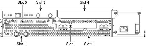
Figure 1-11 Port Adapter Slots in the Cisco 7100 Series Router—Cisco 7140 Series

Cisco 7200 Series and Cisco uBR7200 Series Routers Slot Numbering
Figure 1-12 shows a Cisco 7206 with port adapters installed. In the Cisco 7206 (including the Cisco 7206 and Cisco 7206VXR as router shelves in a Cisco AS5800 Universal Access Server), port adapter slot 1 is in the lower left position, and port adapter slot 6 is in the upper right position. (The Cisco 7202 and Cisco 7204 are not shown; however, the PA-2FEISL can be installed in any available port adapter slot.)
Figure 1-12 Port Adapter Slots in the Cisco 7206

Figure 1-13 shows the slot numbering of port adapters in a Cisco uBR7246 series router. The port adapter slots are numbered slot 1 and slot 2 for the Cisco uBR7246 and slot 1 for the Cisco uBR7223. (Slot 0 is always reserved for the Fast Ethernet port on the I/O controller—if present.)
Figure 1-13 Port Adapter Slots in the Cisco uBR7246

Cisco VIP2 Slot Numbering
Figure 1-14 shows a VIP motherboard with installed port adapters. With the motherboard oriented as shown in Figure 1-14, the left port adapter is in port adapter slot 0, and the right port adapter is in port adapter slot 1. The slot numbering is the same for the Catalyst RSM/VIP2-15 or VIP2-40. The slots are always numbered 0 and 1.
Figure 1-14 VIP Motherboard with Two Port Adapters Installed—Horizontal Orientation

Identifying Interface Addresses
This section describes how to identify interface addresses for the PA-2FEISL in supported platforms. Interface addresses specify the actual physical location of each interface on a router or switch.
Interfaces on the PA-2FEISL installed in a router maintain the same address regardless of whether other port adapters are installed or removed. However, when you move a port adapter to a different slot, the first number in the interface address changes to reflect the new port adapter slot number.
Interfaces on a PA-2FEISL installed in a VIP2 maintain the same address regardless of whether other interface processors are installed or removed. However, when you move a VIP2 to a different slot, the interface processor slot number changes to reflect the new interface processor slot.
Note ![]() Interface ports are numbered from left to right starting with 0.
Interface ports are numbered from left to right starting with 0.
Table 1-4 explains how to identify interface addresses.
|
|
|
|
|
|---|---|---|---|
Cisco 7120 series routers |
Port-adapter-slot-number/interface-port-number |
Port adapter slot—always 3 Interface port—0 through 1 |
3/0 |
Cisco 7140 series routers |
Port-adapter-slot-number/interface-port-number |
Port adapter slot—always 4 Interface port—0 through 1 |
4/0 |
Cisco 7200 series routers |
Port-adapter-slot-number/interface-port-number |
Port adapter slot—0 through 6 (depends on the number of slots in the router)1 Interface port—0 through 1 |
1/0 |
Cisco uBR7223 router |
Port-adapter-slot-number/interface-port-number |
Port adapter slot—always 11 Interface port—0 through 1 |
1/0 |
Cisco uBR7246 router |
Port-adapter-slot-number/interface-port-number |
Port adapter slot—always 1 Interface port—0 through 1 |
1/0 |
VIP2 in Cisco 7000 series or Cisco 7500 series routers |
Interface-processor-slot-number/port-adapter-slot- |
Interface processor slot—0 through 12 (depends on the number of slots in the router) Port adapter slot—always 0 or 1 Interface port—0 through 1 |
1/1/0 |
1 Port adapter slot 0 is reserved for the Fast Ethernet port on the I/O controller (if present). |
Cisco 7100 Series Addresses
This section describes how to identify the interface addresses used for the PA-2FEISL in Cisco 7100 series routers. The interface address is composed of a two-part number in the format port-adapter-slot-number/interface-port-number. See Table 1-4 for the interface address format.
Cisco 7200 Series and Cisco uBR7200 Series Addresses
This section describes how to identify the interface addresses used for the PA-2FEISL in Cisco 7200 series routers or Cisco uBR7200 series routers. The interface address is composed of a two-part number in the format port-adapter-slot-number/interface-port-number. See Table 1-4 for the interface address format.
In Cisco 7200 series routers, port adapter slots are numbered from the lower left to the upper right, beginning with port adapter slot 1 and continuing through port adapter slot 2 for the Cisco 7202, slot 4 for the Cisco 7204 and Cisco 7204VXR, and slot 6 for the Cisco 7206 and Cisco 7206VXR. (Port adapter slot 0 is reserved for the optional Fast Ethernet port on the I/O controller—if present.) Figure 1-12 shows the interfaces of a PA-2FEISL port adapter in port adapter slot 1 of the Cisco 7206 router.
The interface addresses of the interfaces on the PA-2FEISL in port adapter slot 1 are 1/0 through 1/1 (port adapter slot 1 and interfaces 0 through 1). If the PA-2FEISL was in port adapter slot 4, these same interfaces would be numbered 4/0 through 4/1 (port adapter slot 4 and interfaces 0 through 1).
Figure 1-13 shows port adapters installed in slot 1 and slot 2 of a Cisco uBR7246 router. The port adapter slots are numbered slot 1 and slot 2 for the Cisco uBR7246, and slot 1 for the Cisco uBR7223 and the Cisco uBR7246 VXR. (Slot 0 is always reserved for the Fast Ethernet port on the I/O controller—if present.) The individual interfaces always begin with 0. The number of additional interfaces depends on the number of interface ports on a port adapter.
The interface addresses of the interfaces on a PA-2FEISL in port adapter slot 2 are 2/0 and 2/1 (port adapter slot 2 and interfaces 0 and 1). If the PA-2FEISL was in port adapter slot 1, these same interfaces would be numbered 1/0 and 1/1 (port adapter slot 1 and interfaces 0 and 1).
VIP2 Interface Addresses
This section describes how to identify the interface addresses used for the PA-2FEISL on a VIP2 in Cisco 7000 series and Cisco 7500 series routers.
Note ![]() Although the processor slots in the 7-slot Cisco 7000 and Cisco 7507 and 13-slot Cisco 7513 and Cisco 7576 are vertically oriented and those in the 5-slot Cisco 7010 and Cisco 7505 are horizontally oriented, all Cisco 7000 series and Cisco 7500 series routers use the same method for slot and port numbering.
Although the processor slots in the 7-slot Cisco 7000 and Cisco 7507 and 13-slot Cisco 7513 and Cisco 7576 are vertically oriented and those in the 5-slot Cisco 7010 and Cisco 7505 are horizontally oriented, all Cisco 7000 series and Cisco 7500 series routers use the same method for slot and port numbering.
See Table 1-4 for the interface address format. The interface address is composed of a three-part number in the format interface-processor-slot number/port-adapter-slot-number/interface-port- number.
Figure 1-15 shows a sample Cisco 7505 system. The interface addresses of the PA-2FEISL are 3/1/0 through 3/1/1). If the port adapter was in port adapter slot 0 on the VIP2, these same interface addresses would be numbered 3/0/0 through 3/0/1.
If you remove the VIP2 with the PA-2FEISL (shown in Figure 1-15) from interface processor slot 3 and install it in interface processor slot 2, the interface addresses become 2/1/0 through 2/1/1.
Figure 1-15 Fast Ethernet/ISL Interface Port Number Example—Cisco 7505

Note ![]() If you remove the PA-2FEISL-equipped VIP2 (shown in Figure 1-15) from interface processor slot 3 and install it in interface processor slot 2, the interface addresses become 2/1/0 through 2/1/1.
If you remove the PA-2FEISL-equipped VIP2 (shown in Figure 1-15) from interface processor slot 3 and install it in interface processor slot 2, the interface addresses become 2/1/0 through 2/1/1.
 Feedback