Cisco Performance Routing Engine 5 Hardware Installation Guide
The Cisco Performance Routing Engine 5 (PRE5) is the next-generation processor engine for the Cisco uBR10012 Universal Broadband Routers. The PRE5 module comprises two separate engines or processors—route processor that performs all control functions of the PRE5 and the forward packet engine that performs the Parallel eXpress Forwarding (PXF) function and provides fast path forwarding and output scheduling.
The route processor handles all control traffic and any packets that are unrecognized by the fast path. The route processor also sets up data structures for the forward packet engine.
What is Cisco Performance Routing Engine 5?
With the introduction of the Cisco uBR-MC3GX60V line cards that dramatically increase the downstream capability for the Cisco uBR10012 Universal Broadband Routers to 24 Gbps (if all 8 line card slots are used) and the use of the DOCSIS 3.0 wideband SPAs (with 8 Cisco Wideband SPAs), downstream traffic can increase up to 40 Gbps.
 Note |
The throughput will vary depending on the packet size. |
Important |
Effective with September 09, 2014, the Cisco PRE5 uses a new version of the CPU. You must run the Cisco IOS Release 12.2(33)SCH2 or a later release on the Cisco PRE5 for using the new version of the CPU. The board serial number of the Cisco PRE5 with the new version of the CPU starts with CAT1837XXXX. The deviation label on the board is D507963. |
Note |
The Cisco UBR10 MC5X20 line cards are not supported on the PRE5. |
Note |
Foam gaskets are required if you are replacing an earlier generation of the PRE module with PRE5. |
Features of the Cisco PRE5 module include:
-
512 KB NVRAM
-
4 GB system memory for routing tables
-
256 MB of bootflash memory and 32 MB of read-only memory monitor (ROMMON) flash memory
-
Up to 4 GB of eUSB flash memory
The internal embedded USB (eUSB) flash, a mass storage device on the PRE5 and the external USB flash, replace the low density compact flash card of the PRE4.
These PRE5 USB interfaces are compatible with USB 2.0 specification, and work in the USB-host mode only.
Note
The PRE5 supports only Cisco-certified external USB storage devices.
The Cisco IOS can autodetect the USB disk when it is plugged in. The internal eUSB disk in the PRE5 (the compact flash for PRE4) is recognized as ‘disk0’; the two external USB disks are recognized as ‘disk1’ and ‘disk2’.
-
A 10/100/1000 Megabit Ethernet interface that is the management port of the PRE5
-
Error-correcting code (ECC) on all DRAM-based memory systems to support high availability
-
Online insertion and removal (OIR) support
-
PRE5 insertion and pull out sensor support
-
Four SFP+ for backhaul and four SFP+ for board-to-board wiring on the front panel
-
Enhanced route processor–forward packet engine interface
Redundant PREs
The PRE module supports redundant operation (two PRE modules in a Cisco uBR10012 chassis). If the primary PRE fails, the secondary PRE automatically takes over operation of the chassis. Because all Cisco uBR10012 line cards are physically connected to both the primary and secondary PRE modules, a switchover of PRE modules does not require human intervention to reset the line cards, as they automatically fail over to the redundant PRE. The PRE module is hot-swappable if there is a redundant PRE module in the chassis.
Note |
To achieve high availability or PRE redundancy, you must use the same model of the PREs in the same chassis. If you have PRE4 modules and you wish to upgrade, you must upgrade both PREs to PRE5. |
If there is only one PRE5 installed in the chassis, only four 10G SFP+ interfaces are used; the remaining four 10G SFP+ interfaces are in down state. However, if both PRE5 engines are installed in the chassis, and the board-to-board wires are connected, all eight SFP+ backhaul interfaces are enabled.
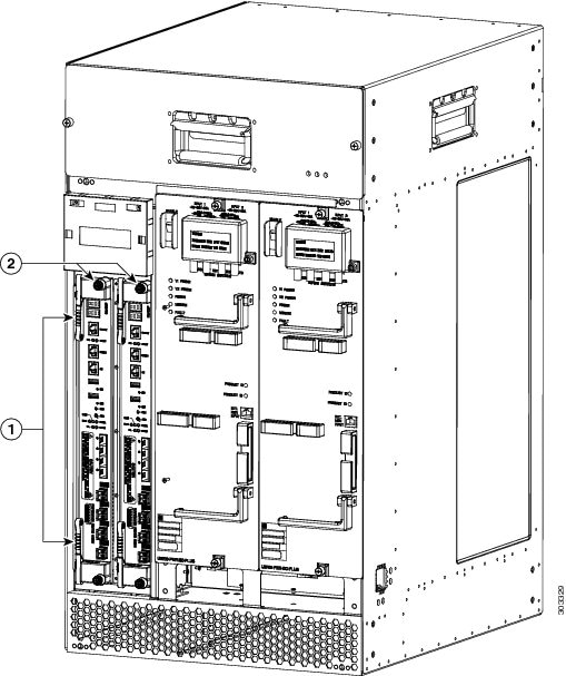
| 1 | Ejector levers | 2 | Captive screws |
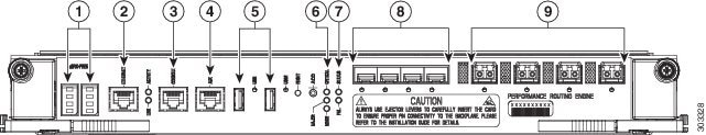
| 1 | Alphanumeric display | 6 | Alarm LEDs |
| 2 | Ethernet port | 7 | Status LEDs |
| 3 | Console port | 8 | 4 SFP+ for board-to-board wiring |
| 4 | Auxiliary port | 9 | 4 SFP+ for backhaul wiring |
| 5 | USB ports | — | |
Connector Ports
The front panel on the PRE contains these ports:
-
Console port—A DCE RS-232 interface used to connect a terminal to the PRE for local administrative access.
-
Auxiliary port (AUX)—A DTE RS-232 interface used to connect a modem to the PRE for remote administrative access.
-
Ethernet port—A 10/100/1000Base-T Management port used network management LAN.
-
USB ports—Used for external USB disks
LEDs
-
Two USB LEDs—display the USB disk status.
-
Three Alarm LEDs—display the system alarm status, whether Critical, Major, or Minor.
-
Two Status LEDs—display the system status to indicate the alarm or failure.
-
Eight SFP+ module status LEDs—display the on-board backhaul interface status.
-
ACTIVITY—if green indicates packets are being transmitted and received.
-
LINK—if green indicates that a carrier is detected and the port is able to pass traffic.
Other Buttons
-
ACO—Alarm Cut-off button. Pressing the ACO button on the (primary) PRE during an alarm condition shuts off the external alarm, but does not deactivate the alarm LEDs on the PRE front panel. Alarm LEDs on the front panel are deactivated only after the condition that caused the alarm is corrected.
-
Alphanumeric Display—displays the ROMMON, IOS system status, license information, or any other debug information.
PRE Disposal
The PRE contains a small lithium battery. Some jurisdictions restrict the ways in which you can dispose items containing lithium batteries. In particular, never dispose of lithium batteries or products containing lithium batteries in an unregulated fire. Other restrictions may apply in your area.
 Warning |
Ultimate disposal of this product should be handled according to all national laws and regulations. Statement 1040. |
Cabling the Cisco PRE5 Module
PRE5 Cable Holder
The Cisco PRE5 module comes with a cable holder for routing the PRE5 cables.
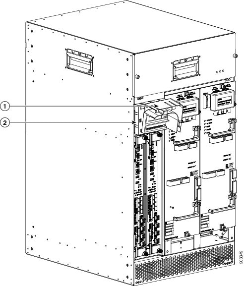
| 1 | PRE5 Cable holder | 2 | Sheetmetal part of the LCD display panel of the Cisco uBR10012 router |
Note |
The cables of PRE5 in the right slot should be routed through this cable holder, so that when the PRE5 module is installed into the left slot, the cables of PRE5 in right slot do not come in the way. |
For information on installing the cable holder, see Attaching the Cisco PRE5 Module Cable Holder.
General Safety Guidelines
When you install any component in a chassis, observe all caution and warning statements mentioned in this chapter. For warning translations, see the regulatory compliance and safety documentation that came with this product.
The following guidelines will help ensure your safety and protect the equipment. However, these guidelines may not cover all potentially hazardous situations you may encounter during system installation, so be alert.
-
Install your product in compliance with the national and local electrical codes. In the United States, this means the National Fire Protection Association (NFPA) 70, United States National Electrical Code. In Canada, Canadian Electrical Code, part I, CC22.1. In other countries, International Electrotechnical Commission (IEC) 364, part 1 through part 7.
-
Review the safety warnings listed in the regulatory compliance and safety documentation before installing, configuring, or performing maintenance on the product.
-
Disconnect power at the source before you install or remove a chassis.
-
Do not attempt to lift an object you might find too heavy to lift safely.
-
Keep the chassis area clear and as dust free as possible during and after installation.
-
Keep tools and chassis components away from walk areas.
-
Do not wear loose clothing, jewelry (including rings and chains), or other items that could get caught in the chassis.
-
Use the product in accordance with its marked electrical ratings and product usage instructions.
Warning |
Only trained and qualified personnel should be allowed to install, replace, or service this equipment. Statement 1030. |
Electrical Equipment Guidelines
- Before beginning any procedures requiring access to the chassis interior, locate the emergency power-off switch for the room in which you are working.
- Disconnect all power and external cables before moving a chassis.
- Do not work alone in potentially hazardous conditions.
- Never assume that power has been disconnected from a circuit; always check.
- Do not perform any action that creates a potential hazard to people or makes the equipment unsafe.
- Carefully examine your work area for possible hazards such as moist floors, ungrounded power extension cables, and missing safety grounds.
Preventing Electrostatic Discharge Damage
Electrostatic discharge (ESD) damage occurs when electronic cards or components are improperly handled, and can result in complete or intermittent failures. All line cards consist of a printed circuit card that is fixed in a metal carrier. Electromagnetic interference (EMI) shielding and connectors are integral components of the carrier. Although the metal carrier helps to protect the cards from ESD, use an antistatic strap each time you handle the modules. Handle the carriers by the edges only; never touch the cards or connector pins.
 Caution |
Always tighten the captive installation screws on all system components when you are installing them. These screws prevent accidental removal of the module, provide proper grounding for the system, and help to ensure that the line card connectors are properly seated in the backplane. Captive screws should be torqued to 6-8 in-lbs to ensure proper grounding and mechanical support. Never use cordless or corded drills to tighten screws; power screwdrivers and hand tools are acceptable. |
Static electricity can harm delicate components inside your system. To prevent static damage, discharge static electricity from your body before you touch any of your system components. As you continue to work on your system, periodically touch an unpainted metal surface on the computer chassis.
The following guidelines can prevent ESD damage:
- Always use an ESD-preventive wrist or ankle strap and ensure that it makes good skin contact. Before removing a card from the chassis, connect the equipment end of the strap to the ESD plug at the bottom of the chassis below the power entry modules. Ensure that the chassis or rack or both have a grounding cable installed.
- Handle line cards by the faceplate and carrier edges only; avoid touching the card components or any connector pins.
- When removing a card, place the removed module component-side-up on an antistatic surface or in a static-shielding bag. If the module will be returned to the factory, immediately place it in a static-shielding bag.
- Avoid contact between the modules and clothing. The wrist-strap protects the card from ESD voltages on the body only; ESD voltages on clothing can still cause damage.
- When transporting a sensitive component, first place it an antistatic container or packaging.
- Handle all sensitive components in a static-safe area. If possible, use antistatic floor pads and workbench pads.
Caution |
For safety, periodically check the resistance value of the antistatic strap. The measurement should be between 1 and 10 megohms. |
Before You Begin
Warning |
Only trained and qualified personnel should be allowed to install, replace, or service this equipment. Statement 1030. |
Before you perform any of the procedures in this guide, we recommend that you:
-
Read the safety guidelines and review the electrical safety and ESD-preventive guidelines provided earlier in this document.
-
Ensure that the software configuration meets the minimum requirement for installation.
-
Ensure that you have all the necessary tools and equipment.
-
Have a terminal console available for configuring the PRE module.
-
Save your configuration information on a TFTP server or the USB disks.
-
Have access to the online documentation for configuring the PRE module.
Removing and Replacing the Cisco PRE5 Module
Note |
If you are upgrading from an earlier version of the PRE to PRE5, review the upgrade procedures in the Upgrading to the Cisco PRE5 Module before continuing with this procedure. |
Equipment
You need the following tools and parts to remove and replace the PRE module. If you need additional equipment, contact a service representative for ordering information:
-
Number 2 Phillips screw driver.
-
Replacement PRE module.
-
ESD-prevention equipment or the disposable grounding wrist strap included with all upgrade kits, FRUs, and spares.
-
Antistatic mat or surface.
Caution |
When performing the following procedures, wear a grounding wrist strap to avoid electrostatic discharge (ESD) damage to the PRE module. Some platforms have an ESD connector for attaching the wrist strap. |
Unpacking the PRE Module
Before you begin
-
Read the safety guidelines and review the electrical safety and ESD-preventive guidelines.
SUMMARY STEPS
- Ensure that you are properly grounded with an ESD-preventive ground strap.
- Open the shipping box.
- Remove the PRE module from the box and place it on an antistatic surface.
DETAILED STEPS
| Step 1 |
Ensure that you are properly grounded with an ESD-preventive ground strap. |
| Step 2 |
Open the shipping box. |
| Step 3 |
Remove the PRE module from the box and place it on an antistatic surface. |
Removing a PRE Module From the Chassis
Warning |
Hazardous voltage or energy is present on the backplane when the system is operating. Use caution when servicing. Statement 1034. |
Before you begin
-
Removing a PRE module terminates all traffic. We recommend that you power down the router to ensure a successful installation.
-
Ensure that you are properly grounded with an ESD-preventive wrist strap.
SUMMARY STEPS
- Save the startup configuration and running configuration to the primary PC media card, redundant PC media card, or the TFTP server (if you are removing a PRE2 or PRE4). If you are removing a PRE5, save the startup configuration and running configuration to the TFTP server or USB disks.
- Power off the router.
- Disconnect the cables from the PRE.
- If you are removing a PRE2 or PRE4 module, remove the PC media card or the CompactFlash Disk from the PRE. If you are removing a PRE5, go to the next step in the procedure.
- Loosen the top and bottom captive screws on the PRE.
- Simultaneously pivot both ejector levers away from each other to disengage the PRE from the backplane.
- Slide the PRE out of the slot and place it on an antistatic surface or in an antistatic bag.
- If you are installing a replacement PRE, proceed to the Installing the Cisco PRE5 Module in the Chassis section. Otherwise, install a blank PRE cover over the slot and screw down the captive screws to complete this procedure.
DETAILED STEPS
| Step 1 |
Save the startup configuration and running configuration to the primary PC media card, redundant PC media card, or the TFTP server (if you are removing a PRE2 or PRE4). If you are removing a PRE5, save the startup configuration and running configuration to the TFTP server or USB disks. |
| Step 2 |
Power off the router. |
| Step 3 |
Disconnect the cables from the PRE. |
| Step 4 |
If you are removing a PRE2 or PRE4 module, remove the PC media card or the CompactFlash Disk from the PRE. If you are removing a PRE5, go to the next step in the procedure. |
| Step 5 |
Loosen the top and bottom captive screws on the PRE. 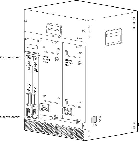 |
| Step 6 |
Simultaneously pivot both ejector levers away from each other to disengage the PRE from the backplane. 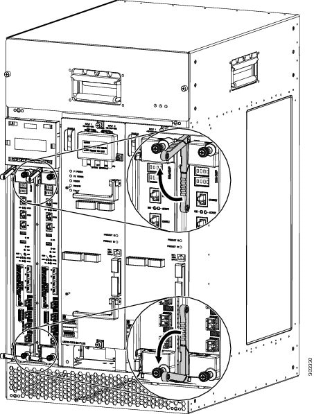 |
| Step 7 |
Slide the PRE out of the slot and place it on an antistatic surface or in an antistatic bag. 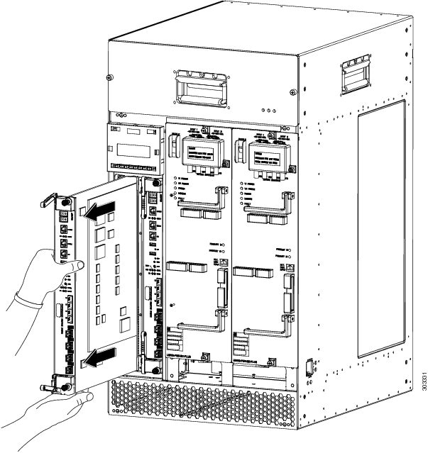 |
| Step 8 |
If you are installing a replacement PRE, proceed to the Installing the Cisco PRE5 Module in the Chassis section. Otherwise, install a blank PRE cover over the slot and screw down the captive screws to complete this procedure. |
Installing the Cisco PRE5 Module in the Chassis
Before you begin
-
Ensure that you are properly grounded with an ESD-preventive wrist strap.
-
Inspect the connectors for any bent or broken pins. Bent or broken pins can cause a system malfunction.
SUMMARY STEPS
- Ensure that the ejector levers on the PRE5 are at the fully-open position.
- Grasp the faceplate of the new PRE with one hand and place your other hand under the module (to support the weight of the module) and position the module in front of the card slot.
- Use your hand to hold the ejector levers and exert a little force in the up and down direction to keep the ejector levers at the fully-open position. Then carefully align the upper and lower edges of the PRE with the upper and lower guides in the slot.
- Slide the PRE5 module into the slot slowly until the ends of both ejector levers touch the front panel surface of the chassis.
- Simultaneously pivot both ejector levers toward each other (until they are parallel to the faceplate) to firmly seat the PRE in the backplane.
- Using a Number 2 Phillips screwdriver, secure the PRE in the chassis by tightening the top and bottom captive screws.
- When fully inserted, the PRE cycles through its power-on self-test. The FAIL LED comes on briefly (about 5 to 6 seconds) and then goes off. If the FAIL LED remains on or is flashing, go to the Troubleshooting the Cisco PRE5 Module Installation section.
- Reconnect the cables.
DETAILED STEPS
| Step 1 |
Ensure that the ejector levers on the PRE5 are at the fully-open position. 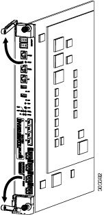 |
||
| Step 2 |
Grasp the faceplate of the new PRE with one hand and place your other hand under the module (to support the weight of the module) and position the module in front of the card slot. 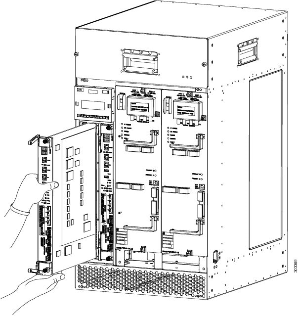 |
||
| Step 3 |
Use your hand to hold the ejector levers and exert a little force in the up and down direction to keep the ejector levers at the fully-open position. Then carefully align the upper and lower edges of the PRE with the upper and lower guides in the slot. 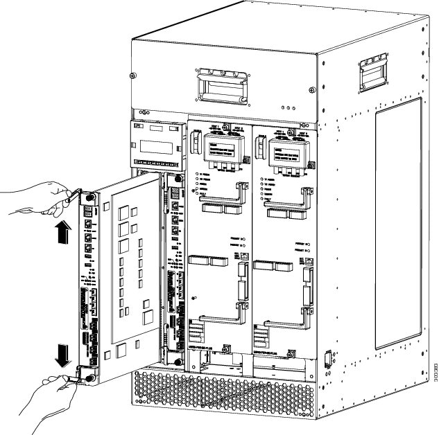 |
||
| Step 4 |
Slide the PRE5 module into the slot slowly until the ends of both ejector levers touch the front panel surface of the chassis. 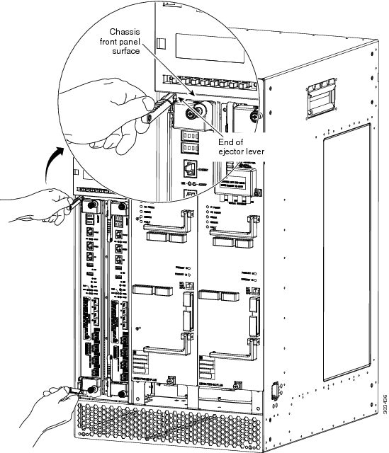 |
||
| Step 5 |
Simultaneously pivot both ejector levers toward each other (until they are parallel to the faceplate) to firmly seat the PRE in the backplane.  |
||
| Step 6 |
Using a Number 2 Phillips screwdriver, secure the PRE in the chassis by tightening the top and bottom captive screws.
|
||
| Step 7 |
When fully inserted, the PRE cycles through its power-on self-test. The FAIL LED comes on briefly (about 5 to 6 seconds) and then goes off. If the FAIL LED remains on or is flashing, go to the Troubleshooting the Cisco PRE5 Module Installation section. |
||
| Step 8 |
Reconnect the cables. For information about configuring the PRE, see the Cisco uBR10012 Universal Broadband Router Software Configuration Guide.
|
Upgrading to the Cisco PRE5 Module
Prerequisites
-
To ensure that all the software features supported by your current PRE image function correctly, they must be supported by the PRE5 image. Check with your Cisco technical support representative to verify the correct upgrade path before initiating the upgrade.
-
The upgrade should be performed by a qualified engineer. This person must be familiar with the Cisco router console interface and be able to perform basic router operations, such as configuration loading and router reload functions.
Important |
See the Installing EMI Gaskets and RF Absorber Material on the Cisco uBR10012 Universal Broadband Router document before proceeding. Ensure that the EMI gaskets and RF absorber material are installed in the Cisco uBR10012 chassis. |
Installing the Foam Gaskets for PRE5
Foam gaskets should be installed on the LCD display panel of the Cisco uBR10012 router to meet the EMI requirements.
- Loosen the four screws on the
LCD display panel and remove it from the chassis.
Note
Place the LCD display panel on an antistatic mat.
- Peel the adhesive backing off the gaskets.
- First align the foam gasket 1
(51-6582-01) 0.180 inches from the edge of the chassis. Then, align and stick
the foam gasket 1 (51-6582-01) along the bottom surface of the base part of LCD
display panel
Figure 12. Installing the Foam Gaskets for PRE5 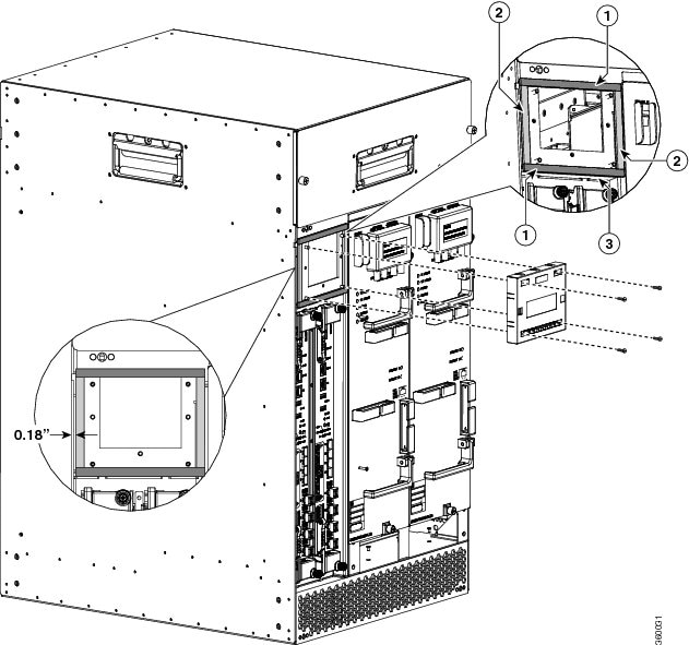
1 Foam gaskets (51-6582-01) 3 Bottom surface of the base part of the LCD display panel 2 Foam gaskets (51-6581-01) —
Note
Ensure that you use the gaskets in strict accordance to the procedure mentioned here.
- Stick the other foam gaskets on the surfaces of the base part of the LCD display panel.
- Reinstall the LCD display panel by tightening the four screws on the LCD display panel.
Upgrade Considerations
-
This is a service-impacting hardware upgrade. The router will not be available for user traffic during the upgrade, and traffic cannot resume until the upgrade is complete.
-
The new PRE image must exist on the TFTP server.
-
The same type of PRE should be used for both, primary and secondary PREs. PREs can operate with the same PRE type only.
-
The PRE5 module must have the helper image (eboot) stored in the bootflash (bootflash0:), must have no configuration, and must be set to boot into ROMMON mode. Individual PRE5 modules ship in this state.
-
When upgrading from a PRE2 or a PRE4, copy your startup configuration and running configuration to the external USB disks (disk1: or disk2:) of the PRE5 module.
Note |
If you have redundant PREs installed in the Cisco uBR10012 chassis, and you intend to save the startup configuration, the running configuration, and the new PRE5 image, be sure to save them to the external USB disks on both the primary and the redundant PRE. |
Saving the Startup and Running Configuration Information
When a PRE is removed from the chassis, any local configuration is lost. You must save your configuration information to the TFTP server or the USB disks before removing the module.
Saving the Startup and Running Configuration Information to the TFTP Server
SUMMARY STEPS
- Connect to the primary PRE console from a terminal.
- Save the startup configuration and running configuration to the TFTP server or USB disks.
DETAILED STEPS
| Step 1 |
Connect to the primary PRE console from a terminal. |
| Step 2 |
Save the startup configuration and running configuration to the TFTP server or USB disks. |
Upgrading the Primary PRE to a Cisco PRE5 Module
SUMMARY STEPS
- Connect a terminal to the primary PRE.
- If you have not already done so, save the startup configuration and running configuration to a location on a TFTP server. For more information, see the Saving the Startup and Running Configuration Information to the TFTP Server.
- Power down the router. All traffic on the router is terminated.
- Remove the PRE (or all PREs in a redundant configuration) from the chassis by following the procedure in the Removing a PRE Module From the Chassis.
- Insert the new PRE into slot A of the chassis by following the procedure in the Installing the Cisco PRE5 Module in the Chassis. If you have a second redundant PRE to install, set it aside until the primary PRE is installed and configured.
- Power up the router. The router boots up in read-only memory monitor mode (ROMMON).
- From the console in ROMMON mode, enter the appropriate boot command.
- Restore the startup configuration and running configuration of the router.
DETAILED STEPS
| Step 1 |
Connect a terminal to the primary PRE. |
||
| Step 2 |
If you have not already done so, save the startup configuration and running configuration to a location on a TFTP server. For more information, see the Saving the Startup and Running Configuration Information to the TFTP Server.
|
||
| Step 3 |
Power down the router. All traffic on the router is terminated.
|
||
| Step 4 |
Remove the PRE (or all PREs in a redundant configuration) from the chassis by following the procedure in the Removing a PRE Module From the Chassis. |
||
| Step 5 |
Insert the new PRE into slot A of the chassis by following the procedure in the Installing the Cisco PRE5 Module in the Chassis. If you have a second redundant PRE to install, set it aside until the primary PRE is installed and configured.
|
||
| Step 6 |
Power up the router. The router boots up in read-only memory monitor mode (ROMMON).
|
||
| Step 7 |
From the console in ROMMON mode, enter the appropriate boot command. For information on booting from the PRE5 image, see the Booting from a TFTP Server, Helper Image, or External Disk. |
||
| Step 8 |
Restore the startup configuration and running configuration of the router. |
Booting from a TFTP Server, Helper Image, or External Disk
Booting From a TFTP Server
If you saved the PRE5 image on a TFTP server that is reachable from the router (for example, if the router and server are on the same LAN or there is a default proxy server), boot the router from the TFTP server.
Note |
These are examples. Your IP address may be different and the image name may change. |
-
Boot the PRE5 image from a network server with an IP address, for example, 172.16.15.112.
> boot tftp://172.16.15.112/ubr10k5-k9p6u2-mz.xxxxx -
In the initial configuration dialog, enter all required information to allow access to the TFTP server.
-
Assign the correct IP address for the Fast Ethernet interface to become active and for the TFTP server to become reachable. This may require adding an IP route for the server even after the initial dialog finishes.
-
Restore the previous configuration from the TFTP server to the startup configuration and running configuration on the router.
-
Restore the startup configuration and running configuration and update any boot commands to use the new PRE5 image.
Booting From the Helper Image
Follow this procedure if you did not save the PRE5 image to a TFTP server.
-
Boot from the helper image, which is shipped with the PRE5 on the bootflash (bootflash:).
> boot bootflash:ubr10k5-eboot-mz.xxxxx -
Exit the configuration dialog and restore the previously saved startup and running configuration from disk0:.
-
Update any boot commands to use the new PRE5 image.
Booting From the External Disk
Follow this procedure if you saved the PRE5 image on an external disk.
-
Boot from the PRE5 image on the external disk.
> boot disk1:ubr10k5-k9p6u2-mz.xxxxx -
Exit the configuration dialog and restore the previously saved startup and running configuration from disk0:.
-
Update any boot commands to use the new PRE5 image.
Upgrading the Secondary PRE of a Redundant Pair of PREs to a Cisco PRE5 Module
SUMMARY STEPS
- Insert the redundant PRE5 into chassis slot B.
- Connect the terminal to the console port of the PRE5 in slot B. The console displays the ROMMON mode prompt (>).
- Upgrade to the PRE5 image by following the instructions listed in the Upgrading the Primary PRE to a Cisco PRE5 Module.
DETAILED STEPS
| Step 1 |
Insert the redundant PRE5 into chassis slot B. |
| Step 2 |
Connect the terminal to the console port of the PRE5 in slot B. The console displays the ROMMON mode prompt (>). |
| Step 3 |
Upgrade to the PRE5 image by following the instructions listed in the Upgrading the Primary PRE to a Cisco PRE5 Module. |
Upgrading the FPGA Image on the Cisco PRE5 Module
You can only upgrade the Field-Programmable Gate Array (FPGA) image on the Cisco PRE5 module manually.
Note |
Automatic upgrade of the PRE5 module is not supported. |
Manual Upgrade of the Cisco PRE5 Module
SUMMARY STEPS
- Cold-boot the active PRE5 module.
- Copy the hw-programmable upgrade package to your hard disk drive as follows:
- Upgrade the active PRE5 module using the upgrade pld {haba | fpld | fp-jpld | rp-jpld} file {url} command.
- Perform Step 1 to Step 3 to upgrade the FPGA on the standby PRE5 module.
- Power cycle the chassis.
DETAILED STEPS
| Step 1 |
Cold-boot the active PRE5 module. |
| Step 2 |
Copy the hw-programmable upgrade package to your hard disk drive as follows: To download this package from Cisco.com, log in with your Cisco.com password to http://www.cisco.com/cisco/software/navigator.html?mdfid=268437899&I=rp. |
| Step 3 |
Upgrade the active PRE5 module using the upgrade pld {haba | fpld | fp-jpld | rp-jpld} file {url} command. |
| Step 4 |
Perform Step 1 to Step 3 to upgrade the FPGA on the standby PRE5 module. |
| Step 5 |
Power cycle the chassis. After the power cycle, the active RP reboots with the latest FPGA programmable firmware and comes online. |
Installing the Cisco PRE5 Module Peripherals
This section describes the peripherals that come with the Cisco PRE5 module and how you can install them. You have two options for the peripherals:
-
Cable holder and PRE5 front-panel bezel—For efficient cable management and to protect cables from being disconnected or damaged by accidental contact.
-
Cable holder and air-filter bezel—For efficient cable management and to avoid dust into the Cisco uBR10012 router.
Installing the Air Filter Bezel on the Cisco uBR10012 Router
The air filter bezel is used to prevent the flow of dust into the Cisco uBR10012 router.
Caution |
To prevent damage to the router, do not attempt to pry off the plastic bezel. |
Before you begin
Read the General Safety Guidelines before installing any module.
SUMMARY STEPS
- Align the stud bolts with the stud holes and push them into the stud holes until the bezel is seated completely.
- Press the air-filter clips towards each other as shown in the figure below, and attach the air-filter clips into the edge of the sheet-metal part of the Cisco uBR10012 router.
DETAILED STEPS
| Step 1 |
Align the stud bolts with the stud holes and push them into the stud holes until the bezel is seated completely. |
||||||||||
| Step 2 |
Press the air-filter clips towards each other as shown in the figure below, and attach the air-filter clips into the edge of the sheet-metal part of the Cisco uBR10012 router. 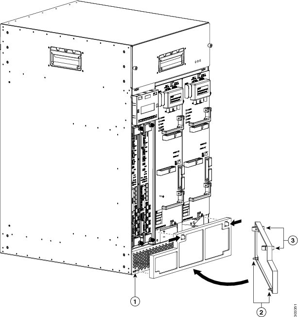
|
||||||||||
Attaching the Cisco PRE5 Module Cable Holder
Before you begin
Have the slotted head screwdriver handy.
SUMMARY STEPS
- Ensure that the twist slugs of the cable holder are at the positions as shown in the figure below.
- Tilt the cable holder a little to insert the clips into the edge of the button slot on the sheet-metal part of the LCD display panel. See Cabling the Cisco PRE5 Module.
- Use the slotted head screwdriver to press the captive screw. Then rotate the captive screw by 90 degrees in the direction shown in the above figure.
DETAILED STEPS
| Step 1 |
Ensure that the twist slugs of the cable holder are at the positions as shown in the figure below. 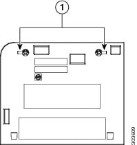
|
||||
| Step 2 |
Tilt the cable holder a little to insert the clips into the edge of the button slot on the sheet-metal part of the LCD display panel. See Cabling the Cisco PRE5 Module. 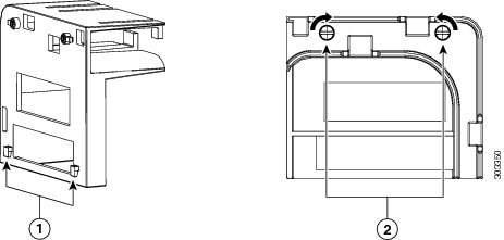
|
||||
| Step 3 |
Use the slotted head screwdriver to press the captive screw. Then rotate the captive screw by 90 degrees in the direction shown in the above figure. The figure below shows how the wires from the PRE5 module in the right hand slot are routed. 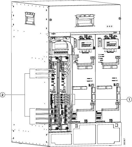
|
||||
Troubleshooting the Cisco PRE5 Module Installation
At system startup, the following sequence should appear on the primary PRE:
-
The FAIL LED should briefly come on (yellow) and go off, and the STATUS LED should start flashing (yellow).
A series of messages should appear on the PRE alphanumeric display, indicating the progress of the boot sequence.
-
On successful completion of the boot sequence, the message IOS RUN should appear on the alphanumeric display.
-
The STATUS LED should be on (green) to indicate that this is the primary PRE.
The sequence on the redundant PRE is similar, except that the STATUS LED remains OFF and the messages on the alphanumeric display are slightly different. The final message upon a successful boot sequence should be IOS STBY to indicate that the PRE is in the standby state.
Check the following if a problem appears on one of the PRE modules.
-
Is the STATUS LED on the primary PRE green at the end of the boot sequence?
-
If no, check the other LEDs on other modules in the chassis. If no other LEDs are on, check for a problem in the power subsystem, as described in the "Troubleshooting the Power Subsystem" section in the Cisco uBR10012 Universal Broadband Router Hardware Installation Guide.
-
If no, and no other LEDs on the PRE are on but LEDs on other modules are on, remove the PRE from the slot, check for any bent or broken pins on the backplane connectors, and reinsert it. Ensure that it makes solid contact with the backplane and is securely locked in by firmly closing both locking levers.
If other LEDs on the PRE modules are on, check the Cisco uBR10012 Universal Broadband Router Troubleshooting Guide for additional instructions.
-
If no, but the FAIL LED is on (yellow), remove the PRE and reinsert it. If that fails, insert a new PRE. If that fails, contact Cisco Technical Assistance for assistance.
-
-
Repeat the above steps for the redundant PRE, except that its STATUS LED should remain OFF and its alphanumeric display should read IOS STBY, if it is operating correctly.
-
Verify the status of the internal Ethernet interface (ethernet0/0/0) of the PRE module, which is used for inter-module communications. If this internal interface is down, it could indicate that the PRE module is not fully seated in its slot or that a hardware failure has occurred.
Router# show interfaces ethernet 0/0/0
Note
Do not confuse the internal Ethernet interface (ethernet0/0/0) of the PRE module with the external Fast Ethernet interface (fastethernet0/0/0) of the PRE module, which is used for network management and remote access.
Alarm Temperature Ranges for the Cisco PRE5 Module
Setting the Automatic Shutdown Command
The facility-alarm critical exceed-action shutdown command allows you to enable or disable the auto-shutdown feature on the Cisco uBR10012 router. When auto-shutdown is enabled, the router shuts down automatically when its core or intake temperature exceeds the critical temperature threshold for 2 minutes.
| Temperature Sensor | Minor | Major | Critical |
|---|---|---|---|
| RP Inlet sensor | 45ºC/113ºF | 55ºC/131F | 60ºC/140ºF |
| RP Core die sensor | 85ºC/185ºF | 95ºC/203ºF | 100ºC/212ºF |
| RP Outlet sensor | 69ºC/156ºF | 79ºC/174ºF | 82ºC/179ºF |
| TITAN sensor | 82ºC/179ºF | 92ºC/197ºF | 95ºC/203ºF |
| Temperature Sensor | Minor | Major | Critical |
|---|---|---|---|
| FP Inlet sensor | 55ºC/131ºF | 65ºC/149ºF | 70ºC/158ºF |
| FP Outlet1 sensor | 87ºC/188ºF | 97ºC/206ºF | 100ºC/212ºF |
| FP Outlet2 sensor | 87ºC/188ºF | 97ºC/206ºF | 100ºC/212ºF |
| COBALT sensor | 90ºC/194ºF | 95ºC/203ºF | 100ºC/212ºF |
-
The auto-shutdown disabled command controls the automatic shutdown action when the critical temperature is exceeded..
-
To enable or disable the auto-shutdown when the critical temperature threshold exceeded for 2 minutes:
facility-alarm [core-temperature | intake-temperature] critical exceed-action shutdown
-
To set the temperature thresholds at which the Cisco uBR100012 router generates a major or minor alarm, or to disable those alarms, use
facility-alarm {intake-temperature | core-temperature} {critical exceed-action shutdown | major [temp] | minor [temp] }
Note |
Configure the facility-alarm outlet-temperature critical exceed-action value on the PRE5 to the desired setting when upgrading to the PRE5 module. |
Troubleshooting Examples for the PRE5 Module
Troubleshooting: Console Port Does not Work
Problem You cannot enter any command on the PRE5 console.
Possible Cause Hardware or software flow control is enabled on the terminal connected to the PRE5 console port.
Solution Disable the hardware and software flow control on the terminal. For more information, see Cisco uBR10012 Universal Broadband Router Hardware Installation Guide.
Cisco PRE5 Module Part Numbers and Specifications
Part Numbers
| Description | Part Number | Minimum Cisco IOS Release |
|---|---|---|
| Performance Routing Engine 5 For Cisco uBR10012 Router, Base Hardware | UBR10-PRE5 | 12.2(33) SCH |
| Performance Routing Engine 5 For Cisco uBR10012 Router, Base Hardware Spare | UBR10-PRE5= | 12.2(33) SCH |
| 10G license, Must Configure With PRE5 Only | SWLIC-PRE5-10G | 12.2(33) SCH |
| 1 count 10G license for PRE51 2 | L-PRE5-10G | 12.2(33) SCH |
| Board to board cable for PRE5 interconnection | CAB-PRE5-BTB | 12.2(33) SCH |
| Cable Holder for PRE5 in Redundant Modeling | PRE5-CAB-HOLDER | 12.2(33) SCH |
| Enhanced Fan Filter for the Cisco uBR10012 Router | UBR10-FAN-FILT-E | 12.2(33) SCH |
| Cable Management Kit for Redundant PRE53 | PRE5-HA-CBLMG-KIT | 12.2(33) SCH |
| 10GBASE-ER SFP Module | SFP-10G-ER | 12.2(33) SCH1 |
| 10GBASE-LR SFP Module | SFP-10G-LR | 12.2(33) SCH |
| 10GBASE-LRM SFP Module | SFP-10G-LRM | 12.2(33) SCH |
| 10GBASE-SR SFP Module | SFP-10G-SR | 12.2(33) SCH |
| 10GBASE-ZR SFP module | SFP-10G-ZR4 | 12.2(33) SCH |
| For more information about the 10GBase SFP modules, see the Cisco 10GBASE SFP+ Modules Data Sheet. | ||
| 1GB USB Flash Token, Spare | MEMUSB-1024FT= | 12.2(33) SCH |
| RJ45 Roll-over Cable (Special cable for the Console/AUX port connection) | 72-5454-01 | 12.2(33) SCH |
| RJ45-DB9 Cable (this cable connects the Console/AUX port on the PRE5 to the 9 pins D-type RS232 port on a PC) | 72-5455-01 | 12.2(33) SCH |
| Cisco Dense Wavelength-Division Multiplexing (DWDM) SFP Modules, Spare | For part number information, see the Cisco 10GBASE Dense Wavelength-Division Multiplexing SFP+ Modules Data Sheet. | 12.2(33) SCH1 |
Specifications
| Description | Specification | ||
|---|---|---|---|
| Card dimension: height x width x depth | 1.965” x 16.52” x 11.0381” | ||
| Weight | 5.05 kg (11.134 lbs) | ||
| Power Consumption | 248 W (active PRE), 207 W (standby PRE) | ||
| Thermal heat Dissipation | 248 W (active PRE), 207 W (standby PRE) | ||
| Mean Time Between Failure (MTBF) |
176330 hours at 40°C inlet temperature |
||
| Temperature Range |
Storage temperature: –38 to 150°F (–40 to 70°C) Operating temperature, nominal: 41 to 104°F (5 to 40°C) Operating temperature, short term: 23 to 122°F (–5 to 50°C) |
||
| Relative Humidity (RH) |
Storage relative humidity: 5 to 95 percent RH Operating humidity, nominal: 5 to 85 percent RH Operating humidity, short term: 5 to 90 percent RH |
||
| Standards, Compliance, Protocols |
Safety
Electromagnetic Emissions Certification
Network Equipment Building Standards (NEBS)
|
||
| Software Requirements |
Cisco IOS Release 12.2(33)SCH or a later release
|
Onboard Failure Logging
The On-Board Failure Logging (OBFL) feature enables storage and collection of critical failure information in the nonvolatile memory of the PRE5.
The OBFL stored data assists in understanding and debugging field failures upon RMA (Return Material Authorization) of a PRE at repair and failure analysis sites. OBFL records operating temperatures, hardware uptime, interrupts, and any other important events that assist board diagnosis in case of hardware failures.
For more information on the feature, see the Onboard Failure Logging feature guide.
Note |
The output from the Cisco CMTS router may vary slightly compared to the output samples shown in the URL mentioned above. |
Logging details for OBFL
-
OBFL is enabled by default. You need to enable the feature if it has been disabled previously.
-
On the PRE, logging begins after the system starts up.
-
OBFL updates the PRE temperatures and voltage sensors every 5 minutes.
-
Temperature and voltage data is stored only when it is different from the last stored record.
-
The maximum logging time is 2 hours, hence, a new record is stored every 2 hours, regardless of data variation.
-
Logs are organized as current (continuous) and historical (summarized) data records.
-
OBFL logging has no impact on performance.
Storing OBFL Data
The PRE logs are recorded in the bootflash, where other system images, configuration information, and crash dumps are stored. OBFL logs are identified by the extension (*_hist or *_cont). The maximum memory used on the flash disk for OBFL storage is 2 MB.
The dir bootflash command displays a list of log files (including OBFL logs). Given below is a sample output of the additional filenames in use by OBFL:
Router# dir bootflash:
Directory of bootflash:/
4  -rw- 202752 Jan 4 2013 16:13:10 -05:00 env_cont
5  -rw- 69120  Jan 4 2013 16:13:12 -05:00 temp_hist
13 -rw- 69120  Jan 4 2013 16:13:12 -05:00 volt_hist
14 -rw- 33792  Jan 4 2013 16:13:12 -05:00 uptime_cont
15 -rw- 201216 Jan 4 2013 16:13:18 -05:00 errmsg_cont
16 -rw- 67584  Jan 4 2013 16:13:16 -05:00 env_hist
17 -rw- 135168 Jan 4 2013 16:13:18 -05:00 temp_cont
18 -rw- 135168 Jan 4 2013 20:17:28 -05:00 volt_cont
19 -rw- 6144   Jan 4 2013 16:13:14 -05:00 uptime_exthist
20 -rw- 4096   Jan 4 2013 16:13:16 -05:00 uptime_hist
Displaying OBFL Data
The show logging onboard [status] command displays the logs from the OBFL data.
For information on OBFL commands, see the Configuration Tasks section in the Onboard Failure Logging feature guide.
Additional References
Related Documents
| Related Topic | Document Title |
|---|---|
| Cisco uBR10012 Universal Broadband Router Hardware Installation Guide | http://www.cisco.com/en/US/partner/docs/cable/cmts/ubr10012/installation/guide/hig.html |
| Cisco uBR10012 Universal Broadband Router Performance Routing Engine Module | http://www.cisco.com/en/US/partner/docs/interfaces_modules/cable/performance_routing_engine/installation/guide/pre5096.html |
Technical Assistance
| Description | Link |
|---|---|
|
The Cisco Support website provides extensive online resources, including documentation and tools for troubleshooting and resolving technical issues with Cisco products and technologies. To receive security and technical information about your products, you can subscribe to various services, such as the Product Alert Tool (accessed from Field Notices), the Cisco Technical Services Newsletter, and Really Simple Syndication (RSS) Feeds. Access to most tools on the Cisco Support website requires a Cisco.com user ID and password. |
 Feedback