Configuring the Cisco uBR10012 OC-48 DPT/POS Interface Module with PRE1 and PRE2 Performance Routing Engines
Available Languages
Table Of Contents
Configuring the Cisco uBR10012 OC-48 DPT/POS Interface Module with PRE1 and PRE2
Prerequisites for Configuring the Cisco uBR10012 OC-48 DPT/POS Interface Module
Restrictions for Configuring the Cisco uBR10012 OC-48 DPT/POS Interface Module
Information About the Cisco OC-48 DPT⁄POS Interface Module
How to Configure the Cisco OC-48 DPT⁄POS Interface Module
Preconfiguring the Slots for the Cisco OC-48 DPT⁄POS Interface Module
Configuring POS Interfaces on the Cisco OC-48 DPT⁄POS Interface Module
Default Values in POS Mode for the Cisco OC-48 DPT⁄POS Interface Module
Configuring the Cisco OC-48 DPT⁄POS Interface Modules for POS
Configuring SRP Interfaces on the Cisco OC-48 DPT⁄POS Interface Module
Default Values in SRP Mode for the Cisco OC-48 DPT⁄POS Interface Module
Configuring the Cisco OC-48 DPT⁄POS Interface Modules for SRP
Configuring the Interface to Support SRP
Configuring the SRP IPS Command Options
Configuring SDCC Interfaces on the Cisco OC-48 DPT⁄POS Interface Module
Cisco OC-48 DPT⁄POS Interface Module System Messages
Configuring the Cisco uBR10012 OC-48 DPT/POS Interface Module with PRE1 and PRE2
OL-3551-03
Product Part Numbers: UBR10-SRP-OC48SMS, UBR10-SRP-OC48SML, ESR10C48/P/SRPSMS, ESR10C48/P/SRPSML
April, 2009This document describes procedures and Cisco IOS commands for configuring and monitoring the Cisco OC-48 DPT⁄POS interface module on the Cisco uBR10012 router.
The Cisco OC-48 DPT⁄POS interface module is a dual-mode module, providing interface support for Packet over SONET (POS) or Spatial Reuse Protocol (SRP).

Note
The Cisco OC-48 DPT⁄POS interface module supports SONET Section Data Communications Channel (SDCC) in either POS or SRP modes.
•
•
Feature History for Cisco OC-48 DPT⁄POS Interface Module
Finding Support Information for Platforms and Cisco IOS Software Images
Use Cisco Feature Navigator to find information about platform support and Cisco IOS software image support. Access Cisco Feature Navigator at http://www.cisco.com/go/fn. You must have an account on Cisco.com. If you do not have an account or have forgotten your username or password, click Cancel at the login dialog box and follow the instructions that appear.
Contents
•
•
•
•
•
Note
Prerequisites for Configuring the Cisco uBR10012 OC-48 DPT/POS Interface Module
The Cisco uBR10012 router should be operational before beginning the configuration procedures in this document. The configuration of the Cisco OC-48 DPT⁄POS interface module requires that the following conditions be met:
•
•
•
•
–
–
–
–
–
•
•
Restrictions for Configuring the Cisco uBR10012 OC-48 DPT/POS Interface Module
The following operational considerations apply to the Cisco OC-48 DPT⁄POS interface module:
•
•
•
•
Information About the Cisco OC-48 DPT⁄POS Interface Module
Faceplate and LED Features
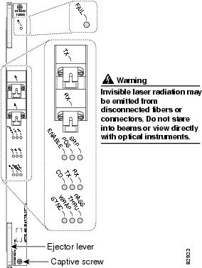
The Cisco OC-48 DPT⁄POS interface module has a pair of OC-48c, fiber-optic standard connector (SC) duplex ports that provide an SC connection for either the single-mode short-reach or single-mode long-reach version. Figure 1 shows the faceplate and LED features of the Cisco OC-48 DPT⁄POS interface module.
Figure 1 Cisco OC-48 DPT Interface Module Faceplate
How to Configure the Cisco OC-48 DPT⁄POS Interface Module
This section contains the following procedures:
•
•
•
•
Preconfiguring the Slots for the Cisco OC-48 DPT⁄POS Interface Module
This section includes the following required and optional subsections:
You must issue the hw-module slot x { pos | srp } and card commands to assign the supported mode to the interface module pairs and to preconfigure the slots to which the interface module pairs are assigned. Perform this preconfiguration prior to any additional POS or SRP mode configurations. Refer to the Cisco IOS CMTS Cable Command Reference Guide for additional command syntax information that applies to additional field-replaceable units (FRUs).

Tip
Perform the following steps to preconfigure the Cisco OC-48 DPT⁄POS interface module slots to support POS or SRP.
SUMMARY STEPS
1.
2.
3.
4.
5.
DETAILED STEPS
Step 1
enable
Example:Router> enable
Enables privileged EXEC mode.
•
Step 2
configure terminal
Example:Router# configure terminal
Enters global configuration mode and specifies that the console terminal will be the source of the configuration commands.
Step 3
hw-module slot slot-number { pos | srp }
no hw-module slot x { pos | srp }
Example:Router# hw-module slot 3 pos
Assigns the mode of operation to the interfaces. To change the mode of operation for the pairs of interface modules, first issue the no form of this command prior to setting it to the new mode.
Refer to the hw-module slot pos command topic for additional command reference information.
Note
Note
Step 4
card slot/port {1oc48dpt-pos-1}
Example:Router# card 3/0 1oc48dpt/pos-1
Preprovisions a slot in the Cisco uBR10012 router for a particular interface module. To remove the preprovisioning for a card, so that the physical slot reports being empty, use the no form of this command.
Note
Refer to the card command topic for additional command reference information.
Step 5
copy running-config startup-config
Example:Router# copy running-config startup-config[OK]Router#Writes the new configuration to nonvolatile random access memory (NVRAM).
The system displays an OK message when the configuration has been stored.
Note
Note
Examples
This section provides the following out put examples:
•
•
•
POS Interface Preprovision Example with card Command
The following example shows a list of supported card types for Cisco IOS 12.3(9a)BC, and then shows that slot 3/0/0 is being preprovisioned for a Cisco uBR-LCP2-MC28C cable interface line card. The POS interface for slot 3/0/0 can then be configured.
Router(config)# card 3/0 ?1cable-mc14c create a uBR10000 line card with MC14C1cable-mc16c create a uBR10000 line card with MC16C1cable-mc16e create a uBR10000 line card with MC16E1cable-mc16s create a uBR10000 line card with MC16S1choc12-1 create a CHOC12_1_PORT cardtype1gigethernet-1 create a GE_1_PORT cardtype1oc12atm-1 create a OC12ATM_1_PORT cardtype1oc12pos-1 create a OC12POS_1_PORT cardtype1oc48dpt-pos-1 create a uBR10000 oc48 SRP/POS card2cable-mc26bnc create a uBR10000 line card with MC26C, BNC connector2cable-mc26c create a uBR10000 line card with MC26C2cable-mc28bnc create a uBR10000 line card with MC28C, BNC connector2cable-mc28c create a uBR10000 line card with MC28C2cable-tccplus Utility Card2oc12srp-mm create a uBR10000 oc12 SRP card with MM2oc12srp-sm-ir create a uBR10000 oc12 SRP card with SM IR2oc12srp-sm-lr create a uBR10000 oc12 SRP card with SM LR2oc12srp-sm-xr create a uBR10000 oc12 SRP card with SM XR5cable-mc520s create a uBR10000 line card with MC520S5cable-mc520s-bnc create a uBR10000 line card with MC520S-BNC5cable-mc520s-d create a uBR10000 line card with MC520S-D6cht3-1 create a CT3_6_PORT cardtypeubr10k-clc-5x20s create a uBR10000 line card with MC520SRouter(config)# card 3/0 1oc48dpt-pos-1POS Interface Preprovision Examples with show interface pos Command
The following example shows the output from the show interface command for a preprovisioned POS interface in slot 1. The second line of the output shows hardware status.
Note
Router# show interface POS 1/0/0POS1/0/0 is administratively down, line protocol is downPOS2/0/0 is reset, line protocol is downHardware is not presentHardware is Skystone 4402 Sonet FramerMTU 4470 bytes, BW 622000 Kbit, DLY 100 usec,reliability 255/255, txload 1/255, rxload 1/255Encapsulation HDLC, crc 32, loopback not setKeepalive set (10 sec)Scramble disabledLast input never, output never, output hang neverLast clearing of "show interface" counters 10:12:57Input queue: 0/75/0/0 (size/max/drops/flushes); Total output drops: 0Queueing strategy: fifoOutput queue :0/40 (size/max)5 minute input rate 0 bits/sec, 0 packets/sec5 minute output rate 0 bits/sec, 0 packets/sec0 packets input, 0 bytes, 0 no bufferReceived 0 broadcasts, 0 runts, 0 giants, 0 throttles0 input errors, 0 CRC, 0 frame, 0 overrun, 0 ignored, 0 abort0 packets output, 0 bytes, 0 underruns0 output errors, 0 collisions, 0 interface resets0 output buffer failures, 0 output buffers swapped out0 carrier transitionsThe following output displays system information when the OC-48 DPT⁄POS interface module has been inserted and configured in slot 4:
Router# show interface pos 4/0/0POS4/0/0 is up, line protocol is upHardware is Skystone 4402 Sonet FramerInternet address is 20.0.0.2/8MTU 4470 bytes, BW 2488000 Kbit, DLY 100 usec,reliability 255/255, txload 23/255, rxload 23/255Encapsulation HDLC, crc 32, loopback not setKeepalive not setScramble disabledLast input never, output never, output hang neverLast clearing of "show interface" counters 10:08:58Input queue: 0/75/0/0 (size/max/drops/flushes); Total output drops: 0Queueing strategy: fifoOutput queue :0/40 (size/max)10 minute input rate 233831000 bits/sec, 235702 packets/sec10 minute output rate 233831000 bits/sec, 235702 packets/sec4281192169 packets input, 2586851424 bytes, 0 no bufferReceived 0 broadcasts, 0 runts, 0 giants, 0 throttles0 input errors, 0 CRC, 0 frame, 0 overrun, 0 ignored, 0 abort4281192797 packets output, 2587060701 bytes, 0 underruns0 output errors, 0 collisions, 0 interface resets0 output buffer failures, 0 output buffers swapped out0 carrier transitionsRouter#SRP Interface Preprovision Example with show interface srp Command
The following example shows the output from the show interface srp command for a preprovisioned SRP interface module in slot 1/0/0:
Router# show interface s1/0/0SRP1/0/0 is administratively down, line protocol is downHardware is SRP over SONET, address is 0000.0048.2222 (bia 0005.00e1.44c0)Internet address is 48.1.1.2/24MTU 4470 bytes, BW 2488000 Kbit, DLY 100 usec,reliability 255/255, txload 1/255, rxload 1/255Encapsulation SRP2,Side A: loopback not setSide B: loopback not set3 nodes on the ring MAC passthrough set <== Passthrough modeSide A: not wrapped IPS local: IDLE IPS remote: IDLESide B: not wrapped IPS local: IDLE IPS remote: IDLELast input 00:00:12, output 00:00:12, output hang neverLast clearing of "show interface" counters neverInput queue: 0/75/0/0 (size/max/drops/flushes); Total output drops: 0Queueing strategy: fifoOutput queue :0/40 (size/max)Side A: 30 seconds output rate 0 bits/sec, 0 packets/sec30 seconds input rate 0 bits/sec, 0 packets/secSide B: 30 seconds output rate 0 bits/sec, 0 packets/sec30 seconds input rate 0 bits/sec, 0 packets/sec51469 packets input, 2182080 bytes, 0 no bufferReceived 0 broadcasts, 2 runts, 0 giants, 0 throttles5 input errors, 0 CRC, 0 frame, 0 overrun, 3 ignored, 0 abort56834 packets output, 3981898 bytes, 0 underruns0 output errors, 0 collisions, 5 interface resets0 output buffer failures, 0 output buffers swapped outSide A received errors:4 input errors, 0 CRC, 3 ignored,1 framer runts, 0 framer giants, 0 framer aborts,0 mac runts, 0 mac giants, 0 mac abortsSide B received errors:1 input errors, 0 CRC, 0 ignored,1 framer runts, 0 framer giants, 0 framer aborts,0 mac runts, 0 mac giants, 0 mac abortsConfiguring POS Interfaces on the Cisco OC-48 DPT⁄POS Interface Module
This section provides procedures and configuration examples to configure the Cisco OC-48 DPT⁄POS interface module. The command-line interface (CLI) allows you to configure and display parameters for both the DPT and the SONET/SDH framer.
This section contains the following required and optional subsections:
•
•
•
•
•
Default Values in POS Mode for the Cisco OC-48 DPT⁄POS Interface Module
Table 2 lists default values for the Cisco OC-48 DPT⁄POS interface module in POS mode. The table includes the command used for modifying a default value and indicates whether a value needs to be the same (or opposite) on the remote end of the connection.
For additional command information, refer to additional POS topics in this document and to the Cisco IOS CMTS Cable Command Reference Guide.
Configuring the Cisco OC-48 DPT⁄POS Interface Modules for POS
The following procedure is for creating a basic configuration, enabling a POS interface, and specifying IP routing. You might also need to enter other configuration commands, depending on the requirements of your system configuration.
A Cisco uBR10012 router identifies a POS interface address by its line-card slot number and port number, in the format slot/subslot/port. For example, the slot/subslot/port address of an POS interface on a Cisco OC-48 DPT⁄POS interface module installed in line card slot 3, subslot 0 and port 0 is 3/0/0.
Perform the following steps to initially configure two Cisco OC-48 DPT⁄POS interface modules in slot 3 and slot 4 of a Cisco uBR10012 router.
SUMMARY STEPS
1.
2.
3.
4.
5.
6.
7.
8.
9.
10.
11.
12.
13.
14.
15.
16.
DETAILED STEPS
Step 1
enable
Example:Router> enable
Enables privileged EXEC mode.
•
Step 2
configure terminal
Example:Router# configure terminal
Enters global configuration mode and specifies that the console terminal will be the source of the configuration commands.
Step 3
hw-module slot number pos
Example:Router(config)# hw-module slot 3 pos
Router(config)# end
Brings up each Cisco OC-48 DPT⁄POS interface module.
Note
Note
Refer to the hw-module slot pos command reference topic for additional command syntax information.
Step 4
ip routing
Example:Router# ip routing
Enable IP routing by entering the ip routing command in global configuration mode.
Step 5
interface pos slot/subslot/port
Example:Router(config)# interface pos 3/0/0Router(config-if)#
At the prompt, specify the new interface to configure by entering the interface command, followed by the type (pos), and slot/subslot/port (slot number/subslot number/port number).
Step 6
ip address ip-address mask
Example:Router(config-if)# ip address 10.0.0.1 255.255.255.0Router(config-if)#Assigns an IP address and subnet mask to the POS interface.
Step 7
clock source {internal | line}
Example:Router(config)# interface pos 1/0/0Router(config-if)# clock source line
Verify that the default value for the clock source is correct. At the prompt, set the internal or line clock source by using the clock source command.
The default is clock source internal.
Step 8
no cdp enable
Example:Router(config-if)# no cdp enableTurns off the Cisco Discovery Protocol (CDP) in interface configuration mode.
Note
Step 9
pos flag { c2 value | j0 value | s1s0 }
Example:Router(config)# interface pos 5/0/0
Router(config-if)# pos flag c2 0xCF
To select the POS flag, enter the pos flag options interface configuration command with the desired command options. This command is typically used to meet a standards requirement or to ensure interoperability with another vendor's equipment.
For additional command syntax information, refer to the pos flag command reference section.
Step 10
pos framing { sonet | sdh }
Example:Router(config-if)# pos framing sonetTo select framing, enter the pos framing interface configuration command.
For additional command syntax information, refer to the pos framing command reference section.
Step 11
pos report option
Example:Router1(config-if)# pos report allTo select a POS alarm report, enter the pos report option interface configuration command.
For additional command syntax information, refer to the
pos report command reference section.Step 12
pos scramble-atm
Example:Router(config)# interface pos 5/0/0
Router(config-if)# pos scramble-atm
Set the line card to scramble the POS synchronous payload envelope (SPE) using the pos scramble-atm command. SONET payload scrambling applies a self-synchronous scrambler to the SPE of the interface to ensure sufficient bit transition density. The default is no POS SPE scrambling. Use the no form of the command to disable scrambling.
For additional command syntax information, refer to the
pos scramble-atm command reference section.Step 13
pos threshold options
Example:Router(config-if)# pos threshold b1-tca sf-ber 3To select POS alarm thresholds, enter the pos threshold interface configuration command.
Note
•
•
Step 14
Ctrl-Z
Example:Router(config-if)# Ctrl-ZWhen you have included all of the configuration commands to complete the configuration, press Ctrl-Z (press the Control key while you press Z) to exit configuration mode.
Step 15
copy running-config startup-config
Example:Router# copy running-config startup-config[OK]Router#Writes the new configuration to nonvolatile random access memory (NVRAM).
The system displays an OK message when the configuration has been stored.
Step 16
show interface pos slot/subslot/port
Example:Router# show interface pos 3/0/0POS3/0/0 is up, line protocol is up.
.
.
Use the show interface pos slot/subslot/port command to monitor stages of the Cisco IOS download to the line cards.
For additional command information, refer to the
show interface pos command reference section.
Note
Examples
This section provides the following output examples:
•
Cisco OC-48 DPT⁄POS Interface Module POS Configuration Example
Use the show interface pos slot/subslot/port command to display the status of the POS requests.
Note
Router# show interface pos 3/0/0POS3/0/0 is up, line protocol is upHardware is Skystone 4402 Sonet FramerInternet address is 50.0.0.2/8MTU 4470 bytes, BW 2488000 Kbit, DLY 100 usec,reliability 255/255, txload 1/255, rxload 1/255Encapsulation HDLC, crc 32, loopback not setKeepalive not setScramble disabledLast input 00:00:32, output never, output hang neverLast clearing of "show interface" counters 12:04:52Input queue: 0/0/0/0 (size/max/drops/flushes); Total output drops: 0Queueing strategy: fifoOutput queue :0/40 (size/max)5 minute input rate 0 bits/sec, 0 packets/sec5 minute output rate 0 bits/sec, 0 packets/sec725 packets input, 247950 bytes, 0 no bufferReceived 725 broadcasts, 0 runts, 0 giants, 0 throttles0 input errors, 0 CRC, 0 frame, 0 overrun, 0 ignored, 0 abort733 packets output, 247717 bytes, 0 underruns0 output errors, 0 collisions, 0 interface resets0 output buffer failures, 0 output buffers swapped out0 carrier transitionsConfiguring SRP Interfaces on the Cisco OC-48 DPT⁄POS Interface Module
This section provides procedures and configuration examples to configure the Cisco OC-48 DPT⁄POS interface module. The command-line interface (CLI) is provided to configure and display parameters for both the DPT and the SONET/SDH framer.
This section contains the following procedures:
•
•
•
•
Default Values in SRP Mode for the Cisco OC-48 DPT⁄POS Interface Module
Table 3 lists default values for the Cisco OC-48 DPT⁄POS interface module in SRP mode. The table includes the command used for modifying a default value and indicates whether a value needs to be the same (or opposite) on the remote end of the connection.
For additional command information, refer to additional POS topics in this document and to the Cisco IOS CMTS Cable Command Referenc Guide.
Configuring the Cisco OC-48 DPT⁄POS Interface Modules for SRP
The following procedure is for creating a basic configuration, enabling an SRP interface, and specifying IP routing. You might also need to enter other configuration commands depending on the requirements of your system configuration.
The Cisco uBR10012 router identifies an SRP interface address by its line-card slot number and port number, in the format slot/port. For example, the slot/port address of an SRP interface on a Cisco OC-48 DPT⁄POS interface module installed in line card slot 3, subslot 0 and port 0 is 3/0/0.
Note
When two Cisco OC-48 POS/DPT interface modules are to be configured for SRP mode, they must be inserted in slot pairs (1 and 2) or (3 and 4). The line cards are referenced as side A and side B. One interface exists for the two line cards and the layer. The SRP protocol determines which line card on which the interface transmits data, and this is dependent upon the ring topology. The interface resides on the lower slot of the SRP line card pair. Therefore, all configuration commands are referenced using the lower slot number.
Note
Perform the following steps to configure two Cisco OC-48 DPT⁄POS interface modules in slot 3 and slot 4 of a Cisco uBR10012 router for the first time.
SUMMARY STEPS
1.
2.
3.
4.
5.
DETAILED STEPS
Step 1
enable
Example:Router> enable
Enables privileged EXEC mode.
•
Step 2
configure terminal
Example:Router# configure terminal
Enters global configuration mode and specifies that the console terminal will be the source of the configuration commands.
Step 3
hw-module slot slot-number srp
no hw-module slot x srp
Example:Router(config)# hw-module slot 3 srp
Assigns the mode of operation to the interfaces. To change the mode of operation for the pairs of interface modules, first issue the no form of this command prior to setting it to the new mode (srp).
Note
For additional command syntax information, refer to the
hw-module slot srp command reference section.Step 4
end
Example:Router(config)# end
Router#
Returns you to privileged EXEC mode.
Step 5
copy running-config startup-config
Example:Router# copy running-config startup-config
[OK]
Router#
Writes the new configuration to nonvolatile random access memory (NVRAM). The system displays an OK message when the configuration has been stored.
Configuring the Interface to Support SRP
The following procedure is for creating a basic configuration—enabling an interface and specifying IP routing. You might also need to enter other configuration commands, depending on the requirements of your system configuration.
A Cisco uBR10012 router identifies an interface address by its line-card slot number and port number, in the format slot/port. For example, the slot/port address of an interface on a Cisco OC-48 DPT⁄POS interface module installed in line card slot 1 and chassis port 0 is 1/0. Even though the card contains only one port, you must use the slot/port notation.
Use the configure terminal command to enter the configuration mode if you want to change the default configuration values on the Cisco OC-48 DPT⁄POS interface module. Be prepared with the information you will need, such as the IP address (see Table 3).
Use the following procedure to configure the Cisco OC-48 DPT⁄POS interface module. Press the Return key after each configuration step, unless otherwise noted.
SUMMARY STEPS
1.
2.
3.
4.
5.
6.
7.
8.
9.
10.
11.
12.
13.
14.
15.
16.
17.
DETAILED STEPS
Step 1
enable
Example:Router> enable
Enables privileged EXEC mode.
•
Step 2
show version
Example:Router# show version
Confirms that the system recognizes the cards. For sample output, refer to the show version command reference section.
Step 3
show interface srp slot/subslot/port
Example:Router# show interface srp 3/0/0
Router#
Check the status of each port using the show interface srp command in global configuration mode.
For sample output, refer to the show interface srp command reference section.
Step 4
configure terminal
Example:Router# configure terminalRouter(config)#Enters global configuration mode and specifies that the console terminal will be the source of the configuration commands.
Step 5
ip routing
Example:Router(config)# ip routingRouter(config)#Enables IP routing.
Step 6
interface srp slot/subslot/port
Example:Router(config)# interface srp 3/0/0Router(config-if)#
Specifies the new interface to configure, followed by interface type (srp), and slot/subslot/port (line card slot number/subslot number/port number).
Step 7
ip address ip-address mask
Example:Router(config-if)# ip address 10.0.0.1 255.255.255.0Router(config-if)#Assigns an IP address and subnet mask to the SRP interface.
Step 8
srp clock-source line n
Example:Router(config-if)# srp clock-source line a
Router(config-if)#
Router(config-if)# srp clock-source line b
Router(config-if)#
Verifies that the default value for the clock source is correct, where n is the source line.
The default setting is clock source internal. Typically, when two Cisco uBR10012 routers are connected back to back, or are connected over dark fiber, where no external clocking is available, set the clock source on each device to internal. If a router is connected to a SONET/SDH add/drop multiplexer (ADM), configure the clock-source for the clock source line on side A and side B.
Step 9
no cdp enable
Example:Router(config-if)# no cdp enableTurns off the Cisco Discovery Protocol (CDP) in interface configuration mode.
Note
Step 10
srp framing
Example:Router1(config-if)# srp framing sdhRouter1(config-if)#Selects SRP framing for the interface.
Step 11
srp topology-timer
Example:Router1(config-if)# srp topology-timer 60Router1(config-if)#Sets the topology timer frequency in seconds for the specified interface.
Note
Step 12
srp tx-traffic-rate
Example:Router1(config-if)# srp tx-traffic-rate high 622Router1(config-if)# srp tx-traffic-rate low 1866Defines the amount of high and low priority traffic a node can transmit onto the SRP ring. For additional command syntax information, refer to the srp TX-traffic-rate command reference section.
Step 13
srp priority-map transmit
Example:Router1(config-if)# srp priority-map transmit 5Router1(config-if)#Controls which IP packets get queued in the high and low priority transmit queues, with precedence values of 5 to 7 to be queued in the high priority transmit queue, and precendence values of 0 to 4 to be queued in the low priority transmit queue.
The no form of this command removes the tx-traffic-rate from the configuration.
Step 14
srp priority-map transmit value
Example:Router(config-if)# srp priority-map transmit 5Maps SRP packets to a specific SRP priority (greater than or equal to the value setting to the high priority queue).
Note
Step 15
Additional interface configurations.
Add any other interface configurations as you require, such as enabling routing protocols or adjusting interface characteristics.
Step 16
Ctrl-Z
Example:Ctrl-Z
When you have included all of the configuration commands to complete the configuration, enter ^Z (press the Control key while you press Z) to exit configuration mode.
Step 17
copy running-config startup-config
Example:Router# copy running-config startup-config[OK]Router#Writes the new configuration to nonvolatile random access memory (NVRAM).
The system displays an OK message when the configuration has been stored.
Configuring the SRP IPS Command Options
This section explains how to use srp ips command options to insert switches or remove automatic and user-configured switches:
•
•
Note
For example, you can enter a forced-switch command to force data traffic to one side of the ring when a Cisco OC-48 DPT⁄POS interface module is removed from a router slot, or in response to an event. Table 4 provides an explanation of the SRP IPS requests in the order of priority, from highest to lowest.
If a protection switch is requested for a given span on the ring, the node that receives the protection request issues a protection request to the node on the other end of the span using both the short path over the failed span, as the failure may be unidirectional, and the long path, around the ring.
As the protection requests travel around the ring, the protection hierarchy is applied. For example, if a high-priority signal fail (SF) request enters the ring, it overrides a pre-existing lower-priority signal degrade (SD) request. If an event or a user-configured command enters a low-priority request, it is not allowed if a high-priority request is present on the ring.
Note
All protection switches are performed bidirectionally and enter wraps at both ends of a span for transmit and receive directions, even if a failure is only unidirectional.
To enter user-configured SRP IPS requests when they are needed, perform the following steps.
SUMMARY STEPS
1.
2.
3.
4.
5.
6.
7.
8.
9.
DETAILED STEPS
Examples
The following example illustrates configuration for a Cisco uBR10012 router with SRP interfaces in slot 1/subslot 0/port 0.
Router# show running-config interface srp 1/0/0ip address 10.0.0.1 255.255.255.0no shutdownno cdp enableno ip mroute-cacheConfiguring SDCC Interfaces on the Cisco OC-48 DPT⁄POS Interface Module
This section describes how to configure and activate SDCC network interfaces to permit remote management and interoperability with the Cisco OC-48 DPT⁄POS interface module.This topic lists the commands that are available when you configure a SONET Section Data Communications Channel (SDCC) interface on the router.
Note
Perform the following steps to enable, configure and verify the SDCC interface.
SUMMARY STEPS
1.
2.
3.
4.
5.
6.
7.
8.
9.
10.
DETAILED STEPS
Step 1
enable
Example:Router> enable
Enables privileged EXEC mode.
•
Step 2
configure terminal
Example:Router# configure terminal
Enters global configuration mode.
Step 3
sdcc enable
Example:Router(config)# sdcc enable
.
.
.
You must first enable the SDCC interface configuration mode before attempting to configure any SDCC commands. The sdcc enable command enables SDCC configuration on the router in global configuration mode. The default setting is disabled.

Caution
Refer to the "sdcc enable" section for complete command information and example.
Step 4
interface sdcc slot/subslot/port
then
no shutdown
Example:Router(config)# interface sdcc 8/0/0Router (config-if)# no shutdownTo administratively enable an SDCC interface, use the no shutdown command from the interface configuration prompt for the specified interface. The default state of an SDCC interface is adminstratively up.
Step 5
interface sdcc slot/subslot/port
Example:Router(config)# interface sdcc 2/0/0Router(config-if)#Prepares for SDCC interface configuration by selecting an interface, where slot is 1 to 4, subslot is 0, and port is 0.
Step 6
loopback
[no] loopbackExample:Router(config-if)# loopbackConfigures an SDCC interface for an internal loopback test in interface configuration mode. With an internal loopback, packets that are received by the line card from the Route Processor are looped back to the Route Processor without being sent to the line.
Use the no form of the command to stop the loopback test.
The default setting is none.
Step 7
crc { 16 | 32 }
Example:Router(config-if)# crc 16Configures the CRC size for HDLC encapsulation on an SDCC interface to 16 or 32 bits. For command syntax information and configuration examples, refer to the crc command reference section.
•
•
Step 8
mtu mtu bytes
Example:Router(config-if)# mtu 1000
Configures the Maximum Transmission Unit (MTU) that a particular interface can handle (in bytes). The default setting is 1500.
Note
For additional command syntax information and configuration examples, refer to the mtu command reference section.
Step 9
hold-queue number in
Example:Router(config-if)# hold-queue 60 in
Configures a hold queue on an SDCC interface for packets received from the line. For additional command syntax information and configuration examples, refer to the hold-queue command reference section.
Step 10
Ctrl-Z
Example:Router(config-if)# ^ZWhen you have included all of the configuration commands to complete the configuration, enter ^Z (press the Control key while you press Z) to exit configuration mode.
Step 11
show interface sdcc slot/subslot/port
Example:Router# show interface sdcc2/0/0
SDCC2/0/0 is up, line protocol is up
Verifies an SDCC interface configuration on a Cisco uBR10012 router.
For additional display information about the show interface sdcc command, refer to the "show interface sdcc" section.
r
Additional References
Related Documents
Cisco uBR10012 Router Installation and Configuration
•
http://www.cisco.com/en/US/docs/cable/cmts/ubr10012/installation/guide/hig.html
•
http://www.cisco.com/en/US/docs/cable/cmts/ubr10012/configuration/guide/scg.html
•
http://www.cisco.com/en/US/products/hw/cable/ps2209/tsd_products_support_series_home.html
•
http://www.cisco.com/en/US/products/hw/cable/ps2209/prod_release_notes_list.html
•
http://www.cisco.com/en/US/docs/cable/cmts/feature/guide/cmtsfg.html
Cisco OC-48 DPT⁄POS Interface Module Installation
•
•
High Availability
(N+1 Redundancy)•
http://www.cisco.com/en/US/products/hw/cable/ps2209/prod_tech_notes_list.html
•
http://www.cisco.com/en/US/docs/cable/cmts/feature/guide/uFGnpls1.html
Packet Over SONET (POS)
•
http://www.cisco.com/en/US/tech/tk482/tk607/technologies_white_paper09186a0080094699.shtml
Standards
Standards
•
•
MIBs
No new or modified MIBs are supported by this feature. To obtain lists of supported MIBs by platform and Cisco IOS release, and to download MIB modules, go to the Cisco MIB website on Cisco.com at the following URL:
http://www.cisco.com/public/sw-center/netmgmt/cmtk/mibs.shtml
RFCs
No new or modified RFCs are supported by this feature.
Technical Assistance
Command Reference
This section describes the following Cisco IOS commands and messages that pertain to the configuration and monitoring of the Cisco OC-48 DPT⁄POS interface module:
•
•
•
•
•
card
To preprovision a slot in the Cisco uBR10012 router for a particular interface card, so that you can configure the interface without it being physically present in the slot, use the card command in global configuration mode. To remove the preprovisioning for a card, so that the physical slot reports being empty, use the no form of this command.
card slot/port {1cable-mc16c | 1cable-mc16e | 1gigethernet-1 | 1oc12pos-1 | 2cable-mc28bnc | 2cable-mc28c | 2oc12srp-sm-lr}
no card slot/port
Syntax Description
Note
Defaults
An empty card slot is not preprovisioned and cannot be configured or displayed.
Command Modes
Global configuration mode
Command History
Usage Guidelines
This command preprovisions a slot in the Cisco uBR10012 router to accept a particular line card, so that you can configure the interface without the card being physically present in the chassis. This command allows system administrators to plan for future configurations, without having to wait for the physical hardware to first arrive. When the line card does arrive, the installer can bring the card online by inserting the card into the chassis and connecting the necessary cables, without having to do any further configuration using the command-line interface.
The type of card must be appropriate for the slot being specified. Slots 1/0 through 4/0 are reserved for network uplink line cards. Slot 5/0 through 8/1 are reserved for cable interface line cards. Slot 0/0 is reserved for the FastEthernet interface on the PRE1 module and cannot be specified in this command.
Tip
Examples
The following example shows a list of supported card types for Cisco IOS Release 12.2(8)BC1, and then shows that slot 8/0 is being preprovisioned for a Cisco uBR-LCP2-MC28C cable interface line card. The cable interface for slot 8/0 can then be configured.
Router# config tRouter(config)# card 5/0 ?1cable-mc16c create a uBR10000 line card with MC16C1cable-mc16e create a uBR10000 line card with MC16E1gigethernet-1 create a GE_1_PORT cardtype1oc12pos-1 create a OC12POS_1_PORT cardtype2cable-mc28bnc create a uBR10000 line card with MC28C, BNC connector2cable-mc28c create a uBR10000 line card with MC28C2oc12srp-sm-lr create a uBR10000 oc12 SRP card with SM LRRouter(config)# card 8/0 2cable-mc28cRouter(config)# int c8/0Router(config-if)#The following example shows the output from the show interface command for a preprovisioned cable interface. The second line of the output shows that the hardware is not present.
Router# show interface c8/0/0Cable8/0/0 is initializing, line protocol is downHardware is not presentHardware is UBR10000 CLC, address is 0001.6440.d160 (bia 0001.6440.d160)MTU 1500 bytes, BW 27000 Kbit, DLY 1000 usec,reliability 255/255, txload 1/255, rxload 1/255Encapsulation MCNS, loopback not setARP type: ARPA, ARP Timeout 04:00:00Last input never, output never, output hang neverLast clearing of "show interface" counters neverInput queue: 0/75/0/0 (size/max/drops/flushes); Total output drops: 0Queueing strategy: fifoOutput queue :0/40 (size/max)5 minute input rate 0 bits/sec, 0 packets/sec5 minute output rate 0 bits/sec, 0 packets/sec0 packets input, 0 bytes, 0 no bufferReceived 0 broadcasts, 0 runts, 0 giants, 0 throttles0 input errors, 0 CRC, 0 frame, 0 overrun, 0 ignored, 0 abort0 packets output, 0 bytes, 0 underruns0 output errors, 0 collisions, 0 interface resets0 output buffer failures, 0 output buffers swapped outRouter#For additional command information, refer to the Cisco IOS CMTS Cable Command Reference Guide.
crc
To configure the cyclic redundancy check (CRC) size for high-level data link control (HDLC) encapsulation on a cable interface, and to improve data integrity, use the crc command in interface configuration mode. To disable this feature, use the no form of this command.
crc { 16 | 32 }
no crc { 16 | 32 }
Syntax Description
Defaults
The CRC size is set to 32 bits by default.
Command Modes
Interface configuration mode (cable interface only)
Command History
Examples
The following two show interface command examples illustrate the configuration of CRC on POS interfaces:
Router# show interface pos2/0/0POS2/0/0 is up, line protocol is upHardware is Skystone 4402 Sonet FramerInternet address is 10.13.1.1/24MTU 4470 bytes, BW 2488000 Kbit, DLY 100 usec,reliability 255/255, txload 1/255, rxload 1/255Encapsulation HDLC, crc 32, loopback not setKeepalive not setScramble disabledLast input never, output 00:00:08, output hang neverLast clearing of "show interface" counters 00:04:14Input queue: 0/75/0/0 (size/max/drops/flushes); Total output drops: 0Queueing strategy: fifoOutput queue: 0/40 (size/max)5 minute input rate 0 bits/sec, 0 packets/sec5 minute output rate 0 bits/sec, 0 packets/sec0 packets input, 0 bytes, 0 no bufferReceived 0 broadcasts, 4 runts, 0 giants, 0 throttles741 input errors, 479 CRC, 0 frame, 3 overrun, 255 ignored, 0 abort7 packets output, 2591 bytes, 0 underruns0 output errors, 0 collisions, 1 interface resets0 output buffer failures, 0 output buffers swapped out1 carrier transitionsRouter# show interface p3/0/0POS3/0/0 is initializing, line protocol is downHardware is unresponsive or is initializingHardware is Skystone 4402 Sonet FramerInternet address is 11.1.1.2/24MTU 4470 bytes, BW 2488000 Kbit, DLY 100 usec,reliability 255/255, txload 1/255, rxload 1/255Encapsulation HDLC, crc 32, loopback not setKeepalive set (10 sec)Scramble disabledLast input never, output never, output hang neverLast clearing of "show interface" counters 00:00:33Input queue: 0/75/0/0 (size/max/drops/flushes); Total output drops: 0Queueing strategy: fifoOutput queue: 0/40 (size/max)5 minute input rate 0 bits/sec, 0 packets/sec5 minute output rate 0 bits/sec, 0 packets/sec0 packets input, 0 bytes, 0 no bufferReceived 0 broadcasts, 0 runts, 0 giants, 0 throttles0 input errors, 0 CRC, 0 frame, 0 overrun, 0 ignored, 0 abort0 packets output, 0 bytes, 0 underruns0 output errors, 0 collisions, 0 interface resets0 output buffer failures, 0 output buffers swapped out0 carrier transitionsThe following two show interface command examples illustrate the configuration of CRC on SRP interfaces:
Router# show interface srp3/0/0SRP3/0/0 is up, line protocol is upHardware is SRP over SONET, address is 0001.6381.1324 (bia 0001.6381.1324)Internet address is 10.3.1.1/24MTU 4470 bytes, BW 2488000 Kbit, DLY 100 usec,reliability 255/255, txload 1/255, rxload 1/255Encapsulation SRP2, Side A loopback not set Side B loopback not set0 nodes on the ring MAC passthrough not setSide A: not wrapped IPS local: IDLE IPS remote: IDLESide B: not wrapped IPS local: IDLE IPS remote: IDLELast input 00:00:01, output 00:00:01, output hang neverLast clearing of "show interface" counters neverInput queue: 0/75/0/0 (size/max/drops/flushes); Total output drops: 0Queueing strategy: fifoOutput queue: 0/40 (size/max)Side A: 30 seconds output rate 53 bits/sec, 0 packets/sec30 seconds input rate 0 bits/sec, 0 packets/secSide B: 30 seconds output rate 0 bits/sec, 0 packets/sec30 seconds input rate 0 bits/sec, 0 packets/sec20 packets input, 768 bytes, 0 no bufferReceived 0 broadcasts, 59 runts, 0 giants, 0 throttles81 input errors, 20 CRC, 0 frame, 0 overrun, 0 ignored, 2 abort77 packets output, 8087 bytes, 0 underruns0 output errors, 0 collisions, 2 interface resets0 output buffer failures, 0 output buffers swapped outSide A received errors:38 input errors, 10 CRC, 0 ignored,23 framer runts, 0 framer giants, 0 framer aborts,4 mac runts, 0 mac giants, 1 mac abortsSide B received errors:43 input errors, 10 CRC, 0 ignored,30 framer runts, 0 framer giants, 0 framer aborts,2 mac runts, 0 mac giants, 1 mac abortsRouter# show interface srp3/0/0SRP3/0/0 is up, line protocol is upHardware is SRP over SONET, address is 0002.0002.0002 (bia 0005.00e6.57a0)Internet address is 11.1.1.2/24MTU 4470 bytes, BW 2488000 Kbit, DLY 100 usec,reliability 255/255, txload 1/255, rxload 1/255Encapsulation SRP2, Side A loopback not set Side B loopback not set2 nodes on the ring MAC passthrough not setSide A: wrapped IPS local: IDLE IPS remote: IDLESide B: not wrapped IPS local: SF IPS remote: IDLELast input 00:00:01, output 00:00:00, output hang neverLast clearing of "show interface" counters neverInput queue: 0/75/0/0 (size/max/drops/flushes); Total output drops: 0Queueing strategy: fifoOutput queue: 0/40 (size/max)Side A: 5 minutes output rate 0 bits/sec, 0 packets/sec5 minutes input rate 0 bits/sec, 0 packets/secSide B: 5 minutes output rate 0 bits/sec, 0 packets/sec5 minutes input rate 0 bits/sec, 0 packets/sec2703700 packets input, 489982906 bytes, 0 no bufferReceived 0 broadcasts, 13 runts, 5 giants, 0 throttles107 input errors, 87 CRC, 0 frame, 0 overrun, 0 ignored, 2 abort3345501 packets output, 509236961 bytes, 0 underruns0 output errors, 0 collisions, 2 interface resets0 output buffer failures, 0 output buffers swapped outSide A received errors:4 input errors, 2 CRC, 0 ignored,0 framer runts, 2 framer giants, 0 framer aborts,0 mac runts, 0 mac giants, 0 mac abortsSide B received errors:103 input errors, 85 CRC, 0 ignored,13 framer runts, 3 framer giants, 1 framer aborts,0 mac runts, 0 mac giants, 1 mac abortsThe following two show interface command examples illustrate the configuration of CRC on SDCC interfaces:
Router# show interface sdcc3/0/0SDCC3/0/0 is up, line protocol is upHardware is M8260/SKY4402Internet address is 10.13.30.1/24MTU 1500 bytes, BW 192 Kbit, DLY 20000 usec,reliability 255/255, txload 1/255, rxload 1/255Encapsulation HDLC, crc 32, loopback not setKeepalive set (10 sec)Last input 00:00:01, output 00:00:01, output hang neverLast clearing of "show interface" counters neverInput queue: 0/75/0/0 (size/max/drops/flushes); Total output drops: 0Queueing strategy: fifoOutput queue: 0/40 (size/max)5 minute input rate 0 bits/sec, 0 packets/sec5 minute output rate 0 bits/sec, 0 packets/sec30 packets input, 2515 bytes, 0 no bufferReceived 0 broadcasts, 0 runts, 0 giants, 0 throttles0 input errors, 0 CRC, 0 frame, 0 overrun, 0 ignored, 0 abort33 packets output, 3764 bytes, 0 underruns0 output errors, 0 collisions, 2 interface resets0 output buffer failures, 0 output buffers swapped out3 carrier transitionsRouter# show interface sdcc 3/0/0SDCC3/0/0 is up, line protocol is upHardware is M8260/SKY4402Internet address is 10.57.1.1/24MTU 1500 bytes, BW 192 Kbit, DLY 20000 usec,reliability 255/255, txload 1/255, rxload 1/255Encapsulation HDLC, crc 32, loopback not setKeepalive set (10 sec)Last input 00:00:05, output 00:00:03, output hang neverLast clearing of "show interface" counters neverInput queue: 0/75/0/0 (size/max/drops/flushes); Total output drops: 0Queueing strategy: fifoOutput queue :0/40 (size/max)5 minute input rate 0 bits/sec, 0 packets/sec5 minute output rate 0 bits/sec, 0 packets/sec137 packets input, 10762 bytes, 0 no bufferReceived 0 broadcasts, 0 runts, 0 giants, 0 throttles0 input errors, 0 CRC, 0 frame, 0 overrun, 0 ignored, 0 abort139 packets output, 11282 bytes, 0 underruns <--------------0 output errors, 0 collisions, 1 interface resets0 output buffer failures, 0 output buffers swapped out1 carrier transitionshold-queue
To configure a hold queue on an SDCC interface for packets received from the line, use the hold-queue command in SDCC interface configuration mode.
hold-queue number in
Syntax Description
number
The maximum number of packets that the line card will hold in the hold queue, from zero to 80. The default hold queue size is 40 packets.
Defaults
The default hold queue size is set to 40 packets by default.
Command Modes
Interface configuration mode (cable interface only)
Command History
Examples
The following example sets the hold queue at 60 packets for the selected SDCC interface.
Router> enable
Router# config t
Router(config)# interface sdcc3/0/0
Router(config-if)# hold-queue 60 in
hw-module slot pos
To configure a line card slot for Packet over SONET (POS) operation, use the hw-module slot pos command in global configuration mode. To remove the configuration for a line card slot, use the no form of this command.
hw-module slot slot-number pos
no hw-module slot slot-number pos
Syntax Description
slot slot-number
Resets the line cards that are physically present in the specified slot number. Valid range is 1 to 8.
pos
Keyword is required to set the slot for POS.
Defaults
Line card slots are not defined, by default, and must be set to either POS or SRP mode.
Command Modes
Global configuration mode
Command History
Usage Guidelines
You must first use the hw-module slot pos command to preconfigure a line card slot for POS operation of the Cisco uBR10012 OC-48 DPT card before you can configure the card with any further commands. You must also use the card 1oc48dpt-pos-1 command to configure the card slot for the proper card type.
Note
no hw-module slot srp command before you can configure the slots for POS operation using the hw-module slot pos command.
Examples
The following example shows the Cisco uBR10012 OC-48 DPT line card in slot 3 being configured for POS operation:
Router(config)# hw-module slot 3 posRouter(config)# card 3/0 1oc48dpt-pos-1The following example shows the Cisco uBR10012 OC-48 DPT line cards in slots 3 and 4 being reconfigured from SRP operation to POS operation:
Router(config)# no hw-module slot 3 srpRouter(config)# no hw-module slot 4 srpRouter(config)# hw-module slot 3 posRouter(config)# card 3/0 1oc48dpt-pos-1Router(config)# hw-module slot 4 posRouter(config)# card 4/0 1oc48dpt-pos-1hw-module slot srp
To configure a line card slot for Spatial Reuse Protocol (SRP) operation, use the hw-module slot srp command in global configuration mode. To remove the configuration for a line card slot, use the no form of this command.
hw-module slot slot-number srp
no hw-module slot slot-number srp
Syntax Description
Defaults
Line card slots are not defined, by default, and must be set to either POS or SRP mode.
Command Modes
Global configuration mode
Command History
Usage Guidelines
You must first use the hw-module slot srp command to preconfigure a line card slot for SRP operation of a pair of Cisco uBR10012 OC-48 DPT cards before you can configure the cards with any further commands. You must also use the card 1oc48dpt-pos-1 command to configure each card slot for the proper card type.
Tip
Note
Examples
The following example shows the Cisco uBR10012 OC-48 DPT line cards in slots 1 and 2 being configured for POS operation:
Router(config)# hw-module slot 1 srpRouter(config)# card 1/0/0 1oc48dpt-pos-1Router(config)# card 2/0/0 1oc48dpt-pos-1The following example shows the Cisco uBR10012 OC-48 DPT line cards in slots 3 and 4 being reconfigured from POS operation to SRP operation:
Router(config)# no hw-module slot 3 posRouter(config)# no hw-module slot 4 posRouter(config)# hw-module slot 3 srpRouter(config)# card 3/0/0 1oc48dpt-pos-1Router(config)# card 4/0/0 1oc48dpt-pos-1loopback
To enable loopback testing on an SDCC interface, in which data is transmitted from the PRE1 or PRE2 module to the OC-48 line card and back, use the loopback command in interface configuration mode. To stop a loopback test, use the no form of this command.
loopback [line | internal]
[no] loopback [line | internal]
Syntax Description
Defaults
Loopback testing is disabled by default.
Command Modes
Interface configuration mode
Command History
Examples
In the following example, a loopbacktest is set for the OC-48 DPT⁄POS line card in slot 5:
Router(config)# interface pos 5/0/0Router(config-if)# loopback lineFor more information about troubleshooting with loopback testing, refer to the Cisco uBR10012 Universal Broadband Router Performance Routing Engine Module on Cisco.com:
mtu
To define the Maximum Transmission Unit (MTU) that a particular interface can handle (in bytes), use the mtu command in interface configuration mode.
mtu mtu bytes
Syntax Description
mtu bytes
The MTU size in bytes from zero to 1500.
Note
Defaults
The default setting is 1500 bytes.
Command Modes
Global configuration mode
Command History
Examples
The following show interface command example illustrates an MTU byte size of 1500:
Router# show interface sdcc3/0/0SDCC3/0/0 is up, line protocol is upHardware is M8260/SKY4402Internet address is 10.13.30.1/24MTU 1500 bytes, BW 192 Kbit, DLY 20000 usec,reliability 255/255, txload 1/255, rxload 1/255Encapsulation HDLC, crc 32, loopback not setKeepalive set (10 sec)Last input 00:00:01, output 00:00:01, output hang neverLast clearing of "show interface" counters neverInput queue: 0/75/0/0 (size/max/drops/flushes); Total output drops: 0Queueing strategy: fifoOutput queue: 0/40 (size/max)5 minute input rate 0 bits/sec, 0 packets/sec5 minute output rate 0 bits/sec, 0 packets/sec30 packets input, 2515 bytes, 0 no bufferReceived 0 broadcasts, 0 runts, 0 giants, 0 throttles0 input errors, 0 CRC, 0 frame, 0 overrun, 0 ignored, 0 abort33 packets output, 3764 bytes, 0 underruns0 output errors, 0 collisions, 2 interface resets0 output buffer failures, 0 output buffers swapped out3 carrier transitionspos flag
To assign values for specific elements of the SONET frame header and corresponding overhead, use the pos flag command in interface configuration mode. This command is typically used to meet a standards requirement or to ensure interoperability with another vendor's equipment. To restore the default values, use the no form of this command.
pos flag [c2 value] [j0 value] [s1s0 value]
[no] pos flag [c2 value] [j0 value] [s1s0 value]
Syntax Description
Defaults
The default values are as follows:
•
•
•
Command Modes
Interface configuration mode
Command History
Examples
In the following example, the c2 bit is set to 0xCF.
Router(config)# interface pos 4/0/02Router(config-if)# pos flag c2 0xCFpos framing
To set framing to SONET Optical Carrier (OC) or SDH STM, use the pos framing command in interface configuration mode. To restore the default framing mode, use the no form of the command.
pos framing [sdh | sonet]
[no] pos framing
Syntax Description
One difference between SONET and SDH framing is the value of the s0 and s1 bits (s is for size), which are bits 5 and 6 in SONET's H1 byte. SDH uses these bits to form the Administrative Unit (AU) field. The ITU-T G.709 standard (or G.707, which combines G.707, G.708, and G.709) describe the AU pointer. There are two major AU types, listed below:
•
•
The s1s0 bits or flag is unused in SONET. A transmitting POS interface configured with SONET framing sends ss = 00; a receiving SONET device ignores these bits, because they are used to indicate payload mapping type information—which is communicated using other fields. A POS interface configured with SDH framing typically sends ss = 10.
The following table illustrates well-known values for these bits.
00
SONET
11
Reserved
01
Used in older add/drop multiplexers (ADMs).
10
AU3/4. Most implementations in Europe use 3.
Defaults
The framing is set to SONET by default.
Command Modes
Interface configuration mode
Command History
Examples
In the following example, the framing type is set to SONET:
Router(config)# interface pos 5/0/1Router(config-if)# no pos framingpos report
To permit console logging of selected SONET alarms, use the pos report command in interface configuration mode.
pos report {b1-tca | b2-tca | b3-tca | lais | lrdi | pais | plop | prdi | plm-p | sd-ber | sf-ber | slof |
slos | uneq-p}Syntax Description
The alarms are as follows:
Defaults
The following errors are reported by default:
•
•
•
•
•
•
Command Modes
Interface configuration mode
Command History
Usage Guidelines
Reporting an alarm means that the alarm can be logged to the console. Just because an alarm is permitted to be logged does not guarantee that it is logged. SONET alarm hierarchy rules dictate that only the most severe alarm of an alarm group is reported. Whether an alarm is reported or not, you can view the current state of a defect by checking the "Active Defects" line from the show controller pos command output. A defect is a problem indication that is a candidate for an alarm.
For B1, the bit interleaved parity error report is calculated by comparing the BIP-8 code with the BIP-8 code extracted from the B1 byte of the following frame. Differences indicate that section level bit errors have occurred.
For B2, the bit interleaved parity error report is calculated by comparing the BIP-8/24 code with the BIP-8 code extracted from the B2 byte of the following frame. Differences indicate that line level bit errors have occurred.
For B3, the bit interleaved parity error report is calculated by comparing the BIP-8 code with the BIP-8 code extracted from the B3 byte of the following frame. Differences indicate that path level bit errors have occurred.
PAIS is sent by line terminating equipment (LTE) to alert the downstream path terminating equipment (PTE) that it has detected a defect on its incoming line signal.
PLOP is reported as a result of an invalid pointer (H1, H2) or an excess number of new data flag (NDF) enabled indications.
SLOF is detected when a severely error framing (SEF) defect on the incoming SONET signal persists for 3 milliseconds.
SLOS is detected when an all-zeros pattern on the incoming SONET signal lasts 19 plus or minus 3 microseconds or longer. This defect might also be reported if the received signal level drops below the specified threshold.
To determine the alarms that are reported on the interface, use the show controllers pos command.
Examples
The following example enables reporting of SD-BER and LAIS alarms on the interface:
Router(config)# interface pos 3/0/0Router(config-if)# pos report sd-berRouter(config-if)# pos report laisRouter(config-if)# endRouter#Related Commands
interface
Defines the IP addresses of the server, configures an interface type, and enters interface configuration mode.
Displays information about the POS controllers.
pos scramble-atm
To enable SONET payload scrambling, use the pos scramble-atm command in interface configuration mode. To disable SONET payload scrambling, use the no form of this command.
pos scramble-atm
no pos scramble-atm
Syntax Description
This command has no additional keywords or arguments.
Defaults
POS scrambling is disabled by default.
Command Modes
Global configuration mode
Command History
Examples
To enable SONET payload scrambling, use the following command sequence:
Router(config)# interface pos 3/0/0Router(config-if)# pos scramble-atmRouter(config-if)# no shutdownRouter(config-if)# endTo verify that SONET payload scrambling is enabled on an interface, enter the show running-config command. If scrambling is enabled, the following line is displayed in the interface configuration:
pos scramble-atmpos threshold
To set the bit error rate (BER) threshold values of the specified alarms for a POS interface, use the pos threshold command in interface configuration mode. To return to the default setting, use the no form of this command.
pos threshold {b1-tca | b2-tca | b3-tca | sd-ber | sf-ber} rate
no pos threshold {b1-tca | b2-tca | b3-tca | sd-ber | sf-ber} rate
Syntax Description
Options include:
Defaults
Default values follow:
•
•
Command Modes
Interface configuration mode
Command History
Usage Guidelines
For B1, the bit interleaved parity error report is calculated by comparing the BIP-8 code with the BIP-8 code extracted from the B1 byte of the following frame. Differences indicate that section level bit errors have occurred.
For B2, the bit interleaved parity error report is calculated by comparing the BIP-8/24 code with the BIP-8 code extracted from the B2 byte of the following frame. Differences indicate that line level bit errors have occurred.
For B3, the bit interleaved parity error report is calculated by comparing the BIP-8 code with the BIP-8 code extracted from the B3 byte of the following frame. Differences indicate that path level bit errors have occurred.
SF-BER and SD-BER are sourced from B2 BIP-8 error counts (as is B2-TCA). However, SF-BER and SD-BER feed into the APS machine and can lead to a protection switch (if APS is configured).
B1-TCA, B2-TCA, and B3-TCA do nothing more than print a log message to the console (if reports for them are enabled).
To determine the BER thresholds configured on the interface, use the show controllers pos command.
Examples
The following example configures thresholds on the interface:
Router(config)# interface pos 3/0/0Router(config-if)# pos threshold sd-ber 8Router(config-if)# pos threshold sf-ber 4Router(config-if)# pos threshold b1_tca 4Router(config-if)# endRouter#The following example returns the POS sf-ber threshold back to the default (of 3).
Router(config-if)# pos threshold b1-tca sf-ber 3sdcc enable
To enable SDCC before configuring additional SDCC interface settings, use the sdcc enable command in global configuration mode. To disable SDCC mode on the interface and to remove the SDCC interface from the interface list in the configuration, use the no form of this command.
sdcc enable
no sdcc enable
Note
Syntax Description
This command requires no additional keywords or arguments.
Defaults
TheSDCC mode is disabled by default.
Command Modes
Global configuration mode.
Command History
Examples
The following example enables SDCC on the Cisco uBR10012 router, and then enters SDCC interface configuration mode:
Router(config)# sdcc enable
*Sep 17 15:01:31.047: %LINK-3-UPDOWN: Interface SDCC3/0/0, changed state to up
*Sep 17 15:01:31.047: %SNMP-5-LINK_UP: LinkUp:Interface SDCC3/0/0 changed state to up
*Sep 17 15:01:31.047: %LINK-3-UPDOWN: Interface SDCC4/0/0, changed state to up
*Sep 17 15:01:31.047: %SNMP-5-LINK_UP: LinkUp:Interface SDCC4/0/0 changed state to up
*Sep 17 15:01:32.047: %LINEPROTO-5-UPDOWN: Line protocol on Interface SDCC3/0/0, changed state to up
*Sep 17 15:01:32.047: %LINEPROTO-5-UPDOWN: Line protocol on Interface SDCC4/0/0, changed state to up
Router(config)# interface sdcc
Note
Related Commands
For additional commands and procedures for configuring SDCC interface settings, refer to the "Configuring SDCC Interfaces on the Cisco OC-48 DPT⁄POS Interface Module" section.
show controllers cable
To display information about the interface controllers for a cable interface on the Cisco universal broadband router, use the show controllers cable command in privileged EXEC mode.
show controllers cable {slot/port | slot/subslot/port} [downstream | upstream [port]]
Syntax Description
Defaults
This command has no default behavior or values.
Command Modes
Privileged EXEC mode
Command History
Examples
The following is sample output from the show controllers cable upstream command for a Cisco CMTS router with a cable interface card located in slot 4, port 0:
Router# show controllers cable 4/0 upstream 2Cable4/0 Upstream 2 is administratively downFrequency 5.008 MHz, Channel Width 0.200 MHz, QPSK Symbol Rate 0.160 MspsSpectrum Group 4SNR 27.2340Nominal Input Power Level 5 dBmV, Tx Timing Offset 0Ranging Backoff Start 16, Ranging Backoff End 16, Tx Backoff Start 16Tx Backoff End 16, Modulation Profile Group 1part_id=0x3137, rev_id=0x01, rev2_id=0xFFnb_agc_thr=0x0000, nb_agc_nom=0x0000Range Load Reg Size=0x58Request Load Reg Size=0x0EMinislot Size in number of Timebase Ticks is = 8Minislot Size in Symbols =8Bandwidth Requests = 0x0Piggyback Requests = 0x0Invalid BW Requests= 0x0Minislots Requested= 0x0Minislots Granted = 0x0Minislot Size in Bytes = 2UCD Count = 0DES Ctrl Reg#0 = C00C0C43, Reg#1 = 0Table 5 describes the fields shown in the show controllers cable upstream display.
The following is sample output for the downstream connection for slot 3 on port 0 on Cisco CMTS router from the show controllers cable downstream command:
Router# show controllers cable 3/0/0 downstreamCable 3/0/0 Downstream is upFrequency not set, Channel Width 6 MHz, 64-QAM, Symbol Rate 5.056941 MspsFEC ITU-T J.83 Annex A, R/S Interleave I=12, J=17Table 6 describes the fields displayed by the show controllers cable downstream command.
show controller pos
To display details of the POS framer state, use the show controller pos command in privileged EXEC mode.
show controller pos { slot/subslot/port | details | pm }
Syntax Description
Defaults
This command has no default behavior or values.
Command Modes
Privileged EXEC mode
Command History
Examples
Router# show controller pos 3/0/0Redundancy Enabled on interfaceRedundancy Summary (* denotes active channel):Primary card is active* POS3/0/0 Primary GoodPOS4/0/0 Secondary GoodPOS3/0/0SECTIONLOF = 0 LOS = 0 BIP(B1) = 0LINEAIS = 0 RDI = 0 FEBE = 1127 BIP(B2) = 0PATHAIS = 0 RDI = 0 FEBE = 23 BIP(B3) = 0LOP = 0Active Defects: NoneActive Alarms: NoneAlarm reporting enabled for: SF SLOS SLOF B1-TCA B2-TCA PLOP B3-TCAFraming: SONETAPSCOAPS = 0 PSBF = 0State: PSBF_state = Falseais_shut = FALSERx(K1/K2): 0x00/0x00 S1S0 = 0x02, C2 = 0xCFReceive Clock is in RangePATH TRACE BUFFER : STABLERemote hostname : R7582-ubr10k-eastRemote interface: POS3/0/0Remote IP addr : 66.0.0.2Remote Rx(K1/K2): 0x00/0x00 Tx(K1/K2): 0x00/0x00BER thresholds: SF = 10e-3 SD = 10e-6TCA thresholds: B1 = 10e-6 B2 = 10e-6 B3 = 10e-6Optics Type : Single Mode Short ReachPOS4/0/0SECTIONLOF = 0 LOS = 0 BIP(B1) = 0LINEAIS = 0 RDI = 0 FEBE = 0 BIP(B2) = 0PATHAIS = 0 RDI = 0 FEBE = 0 BIP(B3) = 0LOP = 0Active Defects: NoneActive Alarms: NoneAlarm reporting enabled for: SF SLOS SLOF B1-TCA B2-TCA PLOP B3-TCAFraming: SONETAPSCOAPS = 0 PSBF = 0State: PSBF_state = Falseais_shut = FALSERx(K1/K2): 0x00/0x00 S1S0 = 0x00, C2 = 0xCFReceive Clock is in RangePATH TRACE BUFFER : STABLERemote hostname : R7582-ubr10k-eastRemote interface: POS4/0/0Remote IP addr : 0.0.0.0Remote Rx(K1/K2): 0x00/0x00 Tx(K1/K2): 0x00/0x00BER thresholds: SF = 10e-3 SD = 10e-6TCA thresholds: B1 = 10e-6 B2 = 10e-6 B3 = 10e-6Optics Type : Single Mode Short ReachRouter#show controllers sdcc
To display Synchronous Optical Network (SONET) Data Communications Channel (SDCC) parameters for all interfaces on the router, use the show controllers sdcc command in privileged EXEC mode. To display the SDCC parameters for a specific interface, use the slot/subslot/port option.
show controllers sdcc {slot/subslot/port}
Syntax Description
slot/subslot/port
(Optional) Router slot, subslot and port number of a specific SDCC interface; otherwise, the command displays information about all SDCC interfaces in the router.
Defaults
This command has no default behavior or values.
Command Modes
Privileged EXEC mode
Command History
Examples
The following example shows the display for interface 3/0/0:
Router# show controllers sdcc3/0/0Interface SDCC3/0/0 (idb 0x64767AD4)Hardware is M8260/SKY4402Flowbit period is 16 and offset is 15Slot is not in APS mode. Slot is not APS active.SCC Registers:General [GSMR]=0x00000000:0x00000030, Protocol-specific [PSMR]=0x0800Events [SCCE]=0x0000, Mask [SCCM]=0x0000, Status [SCCS]=0x03Transmit on Demand [TODR]=0x0000, Data Sync [DSR]=0x7E7EInterrupt Registers:Config [SICR]=0x00000000, Pending [SIPNR]=0x00030000:0x00008000Mask [SIMR]=0x80007800:0x00E00010Command register [CR]=0x29600000Port A [PADIR]=0xFF43FC3F, [PAPAR]=0x00C00000, [PASOR]=0x00000000[PAODR]=0x00000000, [PADAT]=0x00C40100Port B [PBDIR]=0x0FFCFFCF, [PBPAR]=0x008B0008, [PBSOR]=0x00880008[PBODR]=0x00000000, [PBDAT]=0x04B9CC80Port C [PCDIR]=0x7F7CF3D3, [PCPAR]=0x00030C3C, [PCSOR]=0x00000010[PCODR]=0x00000000, [PCDAT]=0x80820C0CSCC GENERAL PARAMETER RAM (at 0xAFF08100)Rx BD Base [RBASE]=0x1E8, Fn Code [RFCR]=0x18Tx BD Base [TBASE]=0x200, Fn Code [TFCR]=0x18Max Rx Buff Len [MRBLR]=1512Rx State [RSTATE]=0x180095B0, BD Ptr [RBPTR]=0x1E8Tx State [TSTATE]=0x180016AC, BD Ptr [TBPTR]=0x200SCC HDLC PARAMETER RAM (at 0xAFF08138)CRC Preset [C_PRES]=0xFFFFFFFF, Mask [C_MASK]=0xDEBB20E3Errors: CRC [CRCEC]=0, Aborts [ABTSC]=0, Discards [DISFC]=0Nonmatch Addr Cntr [NMARC]=0Retry Count [RETRC]=0Max Frame Length [MFLR]=1508Rx Int Threshold [RFTHR]=1, Frame Cnt [RFCNT]=1User-defined Address 0000/0000/0000/0000User-defined Address Mask 0x0000Tx 492 frames (35075 bytes)Rx 492 frames (37043 bytes)Rx ring with 3 buffers at 0xAFF001E8:00 buf=0xC08384 flags=9000 length=001 buf=0xC07D7C flags=9000 length=002 buf=0xC07774 flags=B000 length=0Tx ring with 3 buffers at 0xAFF00200:00 buf=0xC0B65C flags=0000 length=34301 buf=0xC0B65C flags=0000 length=2402 buf=0xC0B65C flags=2000 length=24show controllers srp
To display information about the traffic on the side A and side B rings, use the
show controllers srp slot/subslot/port command in privileged EXEC mode.show controllers srp [slot/subslot/port] [details]
Syntax Description
Defaults
This command has no default behavior or values.
Command Modes
Privileged EXEC mode
Command History
Usage Guidelines
This command applies to SRP interfaces only.
Examples
The following example shows the line card in slot 3, subslot 0 and port 0.
Router# show controllers srp 3/0/0Router1# show controllers srp 3/0/0SRP3/0/0SRP3/0/0 - Side A (Outer RX, Inner TX)SECTIONLOF = 0 LOS = 0 BIP(B1) = 0LINEAIS = 0 RDI = 0 FEBE = 0 BIP(B2) = 0PATHAIS = 0 RDI = 0 FEBE = 0 BIP(B3) = 0LOP = 0 NEWPTR = 0 PSE = 0 NSE = 0Active Defects:NoneActive Alarms: NoneAlarm reporting enabled for:SLOS SLOF PLOPFraming :SONETRX SONET/SDH bytes:(K1/K2) = 0/0 S1S0 = 0 C2 = 0x16TX SONET/SDH bytes:(K1/K2) = 0/0 S1S0 = 0 C2 = 0x16 J0 = 0xCCClock source :InternalFramer loopback :NonePath trace buffer :StableRemote hostname :Router2Remote interface:SRP3/0/0Remote IP addr :10.1.2.2Remote side id :BBER thresholds: SF = 10e-3 SD = 10e-6TCA thresholds: B1 = 10e-6 B2 = 10e-6 B3 = 10e-6SRP1/0/0 - Side B (Inner RX, Outer TX)SECTIONLOF = 0 LOS = 0 BIP(B1) = 0LINEAIS = 0 RDI = 0 FEBE = 0 BIP(B2) = 0PATHAIS = 0 RDI = 0 FEBE = 0 BIP(B3) = 0LOP = 0 NEWPTR = 0 PSE = 0 NSE = 0Active Defects:NoneActive Alarms: NoneAlarm reporting enabled for:SLOS SLOF PLOPFraming :SONETRX SONET/SDH bytes:(K1/K2) = 0/0 S1S0 = 0 C2 = 0x16TX SONET/SDH bytes:(K1/K2) = 0/0 S1S0 = 0 C2 = 0x16 J0 = 0xCCClock source :InternalFramer loopback :NonePath trace buffer :StableRemote hostname :Router4Remote interface:SRP3/0/0Remote IP addr :10.1.2.4Remote side id :ABER thresholds: SF = 10e-3 SD = 10e-6TCA thresholds: B1 = 10e-6 B2 = 10e-6 B3 = 10e-6Router2#show diag
To display the revision-level information for a Cisco Cable Modem Termination System (CMTS) cable interface, use the show diag command in privileged EXEC mode.
show diag [slot]
Syntax Description
Defaults
This command has no default behavior or values.
Command Modes
Privileged EXEC mode
Command History
Examples
Following is an example of the show diag slot command for a Cisco OC-48 DPT⁄POS interface module installed in slot 3/0.
Router# show diag 3/0Slot/Subslot 3/0:1oc48dpt-pos-1 card, 1 portCard is full slot sizeCard is analyzedCard detected 10:07:51 agoCard uptime 0 days, 12 hours, 35 minutes, 39 secondsCard idle time 0 days, 10 hours, 36 minutes, 47 secondsVoltage status: 3.3V Nominal 2.5V NominalEEPROM contents, slot 3/0:Hardware Revision : 1.0Top Assy. Part Number : 800-12346-03Board Revision : 12Deviation Number : 0-0Fab Version : 03PCB Serial Number : CAB063313USRMA Test History : 00RMA Number : 0-0-0-0RMA History : 00CLEI Code :Unknown Field (type 02FF): FF FF FF FF FF FF FF FFFF FF FF FF FF FF FF FFFF FF FF FF FF FF FF FFFF FF FF FF FF FF FF FFFF FF FF FF FF FF FF FFFF FF FF FF FF FF FF FFFF FF FF FF FF FF FF FFFF FF FF FF FF FF FFLCMON version, slot 3/0LCDOS (C10000 PowerQUICC-II Line Card MONitor Image Version 2 : Release branch:c10k_lc_bgp_reorg 20011120:145454)Built by richv at Tue Nov 20 17:00:15 2001.Reset reason 0x00000003/0x2 (PRE hard reset).Operational Image version, slot 3/0LCDOS (C10000 1 Port OC-48 Quicksilver Line Card Image : DEVELOPMENT BUILD prampate-bb-cr1 /vob/lcdos/obj-c10k-oc48srppos 101) major version 1037024976.Built by prampate at Mon Nov 11 09:29:41 2002.show interface pos
To display information about the interface in POS mode, use the show interface pos command in privileged EXEC mode.
show interface pos slot/subslot/port options
Note
Syntax Description
slot/subslot/port
(Optional) Specifies the router slot and port number of a specific SRP interface; otherwise, the command displays information about all SRP interfaces in the router.
Options include:
Defaults
This command has no default behavior or values.
Command Modes
Privileged EXEC mode
Command History
Examples
Router# show interface pos 3/0/0POS3/0/0 is up, line protocol is upHardware is Skystone 4402 Sonet FramerInternet address is 50.0.0.2/8MTU 4470 bytes, BW 2488000 Kbit, DLY 100 usec,reliability 255/255, txload 1/255, rxload 1/255Encapsulation HDLC, crc 32, loopback not setKeepalive not setScramble enabledLast input 00:39:36, output never, output hang neverLast clearing of "show interface" counters 13:12:56Input queue: 0/0/0/0 (size/max/drops/flushes); Total output drops: 0Queueing strategy: fifoOutput queue :0/40 (size/max)5 minute input rate 0 bits/sec, 0 packets/sec5 minute output rate 0 bits/sec, 0 packets/sec754 packets input, 257868 bytes, 0 no bufferReceived 754 broadcasts, 0 runts, 39 giants, 0 throttles0 input errors, 39 CRC, 0 frame, 0 overrun, 0 ignored, 0 abort803 packets output, 271017 bytes, 0 underruns0 output errors, 0 collisions, 1 interface resets0 output buffer failures, 0 output buffers swapped out1 carrier transitionsRouter#show interface sdcc
To verify a Synchronous Optical Network (SONET) Data Communications Channel (SDCC) interface configuration on a Cisco uBR10012 router, use the show interface sdcc command in privileged EXEC mode.
show interface sdcc slot/subslot/port options
Syntax Description
slot/subslot/port
(Optional) Router slot, subslot and port number of a specific SDCC interface; otherwise, the command displays information about all SDCC interfaces in the router.
Options include:
Defaults
This command has no default behavior or values.
Command Modes
Privileged EXEC mode
Command History
Examples
Router# show interface sdcc2/0/0SDCC2/0/0 is up, line protocol is downHardware is M8260/SKY4402MTU 1500 bytes, BW 192 Kbit, DLY 20000 usec,reliability 255/255, txload 1/255, rxload 1/255Encapsulation HDLC, crc 32, loopback not setKeepalive set (10 sec)Last input never, output 00:00:06, output hang neverLast clearing of "show interface" counters neverInput queue: 0/75/0/0 (size/max/drops/flushes); Total output drops: 0Queueing strategy: fifoOutput queue :0/40 (size/max)5 minute input rate 0 bits/sec, 0 packets/sec5 minute output rate 0 bits/sec, 0 packets/sec0 packets input, 0 bytes, 0 no bufferReceived 0 broadcasts, 0 runts, 0 giants, 0 throttles0 input errors, 0 CRC, 0 frame, 0 overrun, 0 ignored, 0 abort265 packets output, 10196 bytes, 0 underruns0 output errors, 0 collisions, 3 interface resets0 output buffer failures, 0 output buffers swapped out3 carrier transitionsshow interface srp
To show information about a Spatial Reuse Protocol (SRP) interface, use the show interfaces srp command in privileged EXEC mode.
show interfaces srp slot/subslot/port options
Note
Syntax Description
slot/subslot/port
(Optional) Router slot and port number of a specific SRP interface; otherwise, the command displays information about all SRP interfaces in the router.
Options include:
Defaults
This command has no default behavior or values.
Command Modes
Privileged EXEC mode
Command History
Examples
Following is sample output from the show interface srp command for slot 1, subslot 0 and port 0 of a three-node SRP ring:
Router# sh interface s1/0/0SRP1/0/0 is up, line protocol is upHardware is SRP over SONET, address is 0000.0048.2222 (bia 0005.00e1.44c0)Internet address is 48.1.1.2/24MTU 4470 bytes, BW 2488000 Kbit, DLY 100 usec,reliability 255/255, txload 1/255, rxload 1/255Encapsulation SRP2,Side A: loopback not setSide B: loopback not set3 nodes on the ring MAC passthrough not setSide A: not wrapped IPS local: IDLE IPS remote: IDLESide B: not wrapped IPS local: IDLE IPS remote: IDLELast input 00:00:00, output 00:00:00, output hang neverLast clearing of "show interface" counters neverInput queue: 0/75/0/0 (size/max/drops/flushes); Total output drops: 0Queueing strategy: fifoOutput queue :0/40 (size/max)Side A: 30 seconds output rate 208540 bits/sec, 396 packets/sec30 seconds input rate 0 bits/sec, 0 packets/secSide B: 30 seconds output rate 0 bits/sec, 0 packets/sec30 seconds input rate 0 bits/sec, 0 packets/sec21958 packets input, 3096506 bytes, 0 no bufferReceived 0 broadcasts, 581 runts, 2 giants, 0 throttles2328 input errors, 1689 CRC, 0 frame, 0 overrun, 0 ignored, 56 abort2172087 packets output, 133956638 bytes, 0 underruns0 output errors, 0 collisions, 7 interface resets0 output buffer failures, 0 output buffers swapped outSide A received errors:220 input errors, 71 CRC, 0 ignored,115 framer runts, 0 framer giants, 2 framer aborts,25 mac runts, 0 mac giants, 7 mac abortsSide B received errors:2108 input errors, 1618 CRC, 0 ignored,403 framer runts, 2 framer giants, 15 framer aborts,38 mac runts, 0 mac giants, 32 mac aborts### 400 packets through interface g4/0/0 network 218.1.1.1show protocols
To display either the global (system-wide) or the interface-specific status of any configured Level 3 protocol, use the show protocols command in privileged EXEC mode.
show protocols options
Syntax Description
slot/subslot/port
(Optional) Router slot and port number of a specific interface; otherwise, the command displays protocol information about all interfaces in the router.
Options include
Defaults
This command has no default behavior or values.
Command Modes
Privileged EXEC mode
Command History
Examples
The following example illustrates typical information from the show protocols command:
Router# show protocolsGlobal values:Internet Protocol routing is enabledEthernet0/0/0 is up, line protocol is upInternet address is 127.0.0.254/8FastEthernet0/0/0 is up, line protocol is upInternet address is 1.8.35.12/8POS1/0/0 is administratively down, line protocol is downPOS3/0/0 is up, line protocol is upInternet address is 50.0.0.2/8POS4/0/0 is up, line protocol is upInternet address is 20.0.0.2/8Cable6/1/0 is up, line protocol is upCable6/1/1 is up, line protocol is upLoopback0 is up, line protocol is upInternet address is 75.0.0.1/8Router#show running-config
To display the currently running configuration in RAM, use the show running-config command in privileged EXEC mode.
show running-config
Syntax Description
This command has no arguments or keywords.
Defaults
This command has no default behavior or values.
Command Modes
Privileged EXEC mode
Command History
Examples
Router# show running-configBuilding configuration...Current configuration : 2545 bytes!version 12.2no service padservice timestamps debug datetime msecservice timestamps log datetime msecno service password-encryptionservice internal!hostname "R7582-ubr10k-UUT"!boot system flash bootflash:ubr10k-k8p6-mz.oc48.11Nov02no logging consoleenable password poPPee!redundancymain-cpuauto-sync standardfacility-alarm intake-temperature major 49facility-alarm intake-temperature minor 40facility-alarm intake-temperature critical 67facility-alarm core-temperature major 53facility-alarm core-temperature minor 45facility-alarm core-temperature critical 85hw-module slot 3 poshw-module slot 4 poscard 1/0 1oc12pos-1card 1/1 2cable-tccpluscard 3/0 1oc48dpt-pos-1card 4/0 1oc48dpt-pos-1card 6/1 2cable-mc28cno cable qos permission createno cable qos permission updatecable qos permission modemsip subnet-zero!packetcable element_id 474!interface Loopback0ip address 75.0.0.1 255.0.0.0!interface FastEthernet0/0/0ip address 1.8.35.12 255.0.0.0ip accounting precedence inputip accounting precedence output!interface POS1/0/0no ip addressshutdowncrc 32pos report laispos report lrdipos report paispos report prdipos report sd-ber!interface POS3/0/0ip address 50.0.0.2 255.0.0.0no keepalivecrc 32pos scramble-atmpos threshold sf-ber 3hold-queue 0 in!interface POS4/0/0ip address 20.0.0.2 255.0.0.0load-interval 600no keepalivecrc 32pos threshold sf-ber 3!interface Cable6/1/0no ip addresscable downstream annex Bcable downstream modulation 64qamcable downstream interleave-depth 32cable downstream channel-id 0cable upstream 0 shutdowncable upstream 1 shutdowncable upstream 2 shutdowncable upstream 3 shutdown!interface Cable6/1/1no ip addresscable downstream annex Bcable downstream modulation 64qamcable downstream interleave-depth 32cable downstream channel-id 1cable upstream 0 shutdowncable upstream 1 shutdowncable upstream 2 shutdowncable upstream 3 shutdown!router ripnetwork 10.0.0.0network 75.0.0.0!ip default-gateway 1.8.0.1ip classlessip route 1.8.0.0 255.255.0.0 FastEthernet0/0/0ip route 30.0.0.0 255.0.0.0 11.1.1.3ip route 223.255.254.0 255.255.255.0 1.8.0.1ip route 223.255.254.254 255.255.255.255 1.8.0.1no ip http server!cdp runsnmp-server community public ROsnmp-server community private RWsnmp-server enable traps ttytftp-server bootflash:srp-config 1!!line con 0exec-timeout 0 0line aux 0line vty 0 4exec-timeout 0 0password labno loginlength 0!endRouter#show srp
To display Intelligence Protection Switching (IPS) information about each interface, use the show srp slot/subslot/port command in privileged EXEC mode. The output tells you whether an automatic protection switch is enabled or idle.
show srp slot/subslot/port options
Syntax Description
Options include
Defaults
This command has no default behavior or values.
Command Modes
Privileged EXEC mode
Command History
Examples
The following example produces output that displays the IPS, source-counter, and topology status of the SRP interface by using the show srp slot/port command:
Router# show srpIPS Information for Interface SRP2/0MAC AddressesSide A (Outer ring RX) neighbor 0012.3456.0004Side B (Inner ring RX) neighbor 0012.3456.0002Node MAC address 0012.3456.0001IPS StateSide A not wrappedSide B not wrappedSide A (Inner ring TX) IPS pkt. sent every 1 sec. (next pkt. after 0 sec.)Side B (Outer ring TX) IPS pkt. sent every 1 sec. (next pkt. after 0 sec.)IPS WTR period is 60 sec. (timer is inactive)Node IPS State IDLEIPS Self Detected Requests IPS Remote RequestsSide A IDLE Side A IDLESide B IDLE Side B IDLEIPS messages receivedSide A (Outer ring RX) {0012.3456.0002,IDLE,S}, TTL 128Side B (Inner ring RX) {0012.3456.0004,IDLE,S}, TTL 128IPS messages transmittedSide A (Inner ring TX) {0012.3456.0001,IDLE,S}, TTL 128Side B (Outer ring TX) {0012.3456.0001,IDLE,S}, TTL 128Source Address Information for Interface SRP2/00012.3456.0001, index 1, pkt. count 4098470012.3456.0002, index 2, pkt. count 24793300012.3456.0003, index 3, pkt. count 7243840012.3456.0004, index 4, pkt. count 1472439Topology Map for Interface SRP2/0Topology pkt. sent every 10 sec. (next pkt. after 5 sec.)Last received topology pkt. 00:00:04Nodes on the ring:4Hops (outer ring) MAC IP Address Wrapped Name0 0012.3456.0001 10.1.2.1 No Router11 0012.3456.0002 10.1.2.2 No Router22 0012.3456.0003 10.1.2.3 No Router33 0012.3456.0004 10.1.2.4 No Router4Router#Table 7 describes selected fields from the show srp command output.
Table 7 show srp Command Output Fields
Related Commands
show srp ips
To display the status of the Intelligence Protection Switching (IPS) protocol, use the show srp ips command in privileged EXEC mode.
show srp ips
Syntax Description
This command has no additional arguments or keywords.
Defaults
This command has no default behavior or values.
Command Modes
Privileged EXEC mode
Command History
Usage Guidelines
This command displays information such as the direct neighbors' address, the wrap state, the failures state and the latest transmitted and received IPS packets of the SRP node. It also indicates that the interface is administratively up and not in PASS-THRU mode.
Examples
Router# sh srp ipsIPS Information for Interface SRP3/0/0MAC AddressesSide A (Outer ring RX) neighbor 0000.0048.2222Side B (Inner ring RX) neighbor 0000.0048.1111Node MAC address 0000.0048.3333IPS StateSide A not wrappedSide B not wrappedSide A (Inner ring TX) IPS pkt. sent every 1 sec. (next pkt. after 1 sec.)Side B (Outer ring TX) IPS pkt. sent every 1 sec. (next pkt. after 1 sec.)inter card bus enabledIPS WTR period is 60 sec. (timer is inactive)Node IPS State: idleIPS Self Detected Requests IPS Remote RequestsSide A IDLE Side A IDLESide B IDLE Side B IDLESide A Failures: noneSide B Failures: noneIPS messages receivedSide A (Outer ring RX) {0000.0048.2222,IDLE,SHORT}, TTL 255Side B (Inner ring RX) {0000.0048.1111,IDLE,SHORT}, TTL 255IPS messages transmittedSide A (Inner ring TX) {0000.0048.3333,IDLE,SHORT}, TTL 255Side B (Outer ring TX) {0000.0048.3333,IDLE,SHORT}, TTL 255Related Commands
show srp rate-limit
To display the current Spatial Reuse Protocol (SRP) rate-limit configuration for high and low priority traffic, use the show srp rate-limit srp slot/subslot/port command in privileged EXEC mode.
show srp rate-limit srp slot/subslot/port
Syntax Description
slot/subslot/port
(Optional) Router slot, subslot and port number of a specific SRP interface; otherwise, the command displays information about all SRP interfaces in the router.
Defaults
This command has no default behavior or values.
Command Modes
Privileged EXEC mode
Command History
Examples
The following example shows output from the show srp rate-limit srp slot/subslot/port command.
Router# show srp rate-limit srp 3/0/0Router#Rate Limit Information for Interface SRP3/0/0Rate limit of high priority outgoing traffic: 622 MbpsRate limit of low priority outgoing traffic: 1866 MbpsMinimum SRP priority value of high priority outgoing/transit traffic: 5Router#Related Commands
show srp topology
To identify the nodes on the Spatial Reuse Protocol (SRP) ring, use the show srp topology command in privileged EXEC mode.
show srp topology {srp slot/subslot/port}
Syntax Description
srp slot/subslot/port
(Optional) Router slot, subslot and port number of a specific SRP interface; otherwise, the command displays information about all SRP interfaces in the router.
Defaults
This command has no default behavior or values.
Command Modes
Privileged EXEC mode
Command History
Examples
The following sequence of commands displays the nodes on the SRP ring.
Router# show srp topology srp 1/0/0Topology Map for Interface SRP1/0/0Topology pkt. sent every 5 sec. (next pkt. after 3 sec.)Last received topology pkt. 00:00:01Last topology change was 00:01:16 ago.Nodes on the ring: 3Hops (outer ring) MAC IP Address Wrapped SRR Name0 0000.0048.2222 48.1.1.2 No - SRP-10K1 0000.0048.3333 Unknown No - R7557-HC2 0000.0048.1111 48.1.1.1 No - GSRRouter# ping 48.1.1.3Type escape sequence to abort.Sending 5, 100-byte ICMP Echos to 48.1.1.3, timeout is 2 seconds:.!!!!Success rate is 80 percent (4/5), round-trip min/avg/max = 1/1/1 msRouter# show srp topology srp 1/0/0Topology Map for Interface SRP1/0/0Topology pkt. sent every 5 sec. (next pkt. after 3 sec.)Last received topology pkt. 00:00:01Last topology change was 00:01:31 ago.Nodes on the ring: 3Hops (outer ring) MAC IP Address Wrapped SRR Name0 0000.0048.2222 48.1.1.2 No - SRP-10K1 0000.0048.3333 48.1.1.3 No - R7557-HC2 0000.0048.1111 48.1.1.1 No - GSRRouter# show srp topology srp 3/0/0Topology Map for Interface SRP3/0/0Topology pkt. sent every 5 sec. (next pkt. after 1 sec.)Last received topology pkt. 00:00:03Last topology change was 00:16:38 ago.Nodes on the ring: 3Hops (outer ring) MAC IP Address Wrapped SRR Name0 0000.0048.3333 48.1.1.3 No - R7557-HC1 0000.0048.1111 48.1.1.1 No - GSR2 0000.0048.2222 48.1.1.2 No - SRP-10KRelated Commands
show version
To display the configuration of the system hardware (the number of each line card type installed), the Cisco IOS software version, the names and sources of configuration files, and the boot images, use the show version command in privileged EXEC mode.
show version
Syntax Description
This command has no arguments or keywords.
Defaults
This command has no default behavior or values.
Command Modes
Privileged EXEC mode
Command History
Examples
The following show version command return provides an example of support for POS mode.
Router# show versionCisco Internetwork Operating System SoftwareIOS (tm) 10000 Software (UBR10K-K8P6-M), Experimental Version 12.2(20021115:194156) [REL-ftp_p2_clipper_srp.ios-weekly 103]Copyright (c) 1986-2002 by cisco Systems, Inc.Compiled Fri 15-Nov-02 18:05 by richvImage text-base: 0x60008940, data-base: 0x61A80000ROM: System Bootstrap, Version 12.0(9r)SL2, RELEASE SOFTWARE (fc1)R7582-ubr10k-UUT uptime is 10 hours, 14 minutesSystem returned to ROM by power-onSystem image file is "bootflash:ubr10k-k8p6-mz.oc48.15Nov02"cisco uBR10012 (PRE1-RP) processor with 393215K/131072K bytes of memory.Processor board ID TBA05080267R7000 CPU at 262Mhz, Implementation 39, Rev 2.1, 256KB L2, 2048KB L3 CacheBackplane version 1.0, 8 slotLast reset from power-onToaster processor tmc0 is running.Toaster processor tmc1 is running.1 OC12 POS controller (1 POS)1 TCCplus card(s)1 FastEthernet/IEEE 802.3 interface(s)1 Gigabit Ethernet/IEEE 802.3 interface(s)3 Packet over SONET network interface(s)2 Cable Modem network interface(s)509K bytes of non-volatile configuration memory.46976K bytes of ATA PCMCIA card at slot 0 (Sector size 512 bytes).32768K bytes of Flash internal SIMM (Sector size 256KB).Configuration register is 0x0Router#The following show version command return provides an example of support for SRP mode.
Router# sh versionCisco Internetwork Operating System SoftwareIOS (tm) 10000 Software (UBR10K-K8P6-M), Experimental Version 12.2(20021028:080725) [REL-ftp_p2_clipper_srp.ios-weekly 103]Copyright (c) 1986-2002 by cisco Systems, Inc.Compiled Mon 28-Oct-02 08:27 by richvImage text-base: 0x60008940, data-base: 0x61A80000ROM: System Bootstrap, Version 12.0(9r)SL2, RELEASE SOFTWARE (fc1)R7557-HC uptime is 1 hour, 3 minutesSystem returned to ROM by power-onSystem image file is "disk0:ubr10k-k8p6-mz.oc48.28Oct02"cisco uBR10012 (PRE1-RP) processor with 393215K/131072K bytes of memory.Processor board ID TBA06060422R7000 CPU at 262Mhz, Implementation 39, Rev 2.1, 256KB L2, 2048KB L3 CacheBackplane version 1.1, 8 slotLast reset from power-onToaster processor tmc0 is running.Toaster processor tmc1 is running.2 OC12 POS controllers (2 POS)2 TCCplus card(s)1 FastEthernet/IEEE 802.3 interface(s)2 Packet over SONET network interface(s)1 SRP network interface(s)5 Cable Modem network interface(s)509K bytes of non-volatile configuration memory.46976K bytes of ATA PCMCIA card at slot 0 (Sector size 512 bytes).32768K bytes of Flash internal SIMM (Sector size 256KB).Secondary is upSecondary has 524288K bytes of memory.Configuration register is 0x0srp clock-source
To configure the clock source, use the srp clock-source command in interface configuration mode. To restore the default srp clock-source, use the no form of this command .
srp clock-source [line | internal] [a | b]
no srp clock-source [line | internal] [a | b]
Syntax Description
Defaults
The default setting is both interfaces set to internal. This is recommended for optimal clocking.
Command Modes
Interface configuration mode
Command History
Usage Guidelines
This command applies to Spatial Reuse Protocol (SRP) interfaces only.
When you configure a connection between two Cisco 10700 Series Internet Routers, you can configure the SRP interfaces for clock source as follows:
•
•
•
Examples
The following is an example of how to use the srp clock-source command to select line as a clock source on side A:
Router# configure terminalRouter(config)# interface srp 1/0/0Router(config-if)# srp clock-source line aRouter(config-if)#srp flag
To specify SONET/Synchronous Digital Hierarchy (SDH) overhead values for the frame header, use the srp flag command in interface configuration mode. Use the no form of this command to restore the default SRP flag.
srp flag [c2 | j0] value [a | b]
no srp flag [c2 | j0] value [a | b]
Syntax Description
Defaults
The default c2 value is 0x16, and the default j0 value is 0xCC.
Command Modes
Interface configuration mode
Command History
Usage Guidelines
This command applies to SRP interfaces only. Note that the j0 0x1 flag is specified indirectly by the choice of SONET or SDH framing in the srp framing command.
Examples
The following example shows how to use the srp flag command to specify the SONET/SDH overhead values on an SRP interface:
Router# configure terminalRouter(config)# interface srp 1/0/0Router(config-if)# srp flag j0 0x1Router(config-if)#srp framing
To specify Spatial Reuse Protocol (SRP) framing for the packet header and trailer to ensure synchronization and error control, use the srp framing command in interface configuration mode. To restore the default value for SRP framing, use the no form of this command .
srp framing [sdh | sonet] [a | b]
no srp framing [a | b]
Syntax Description
Defaults
SRP framing is disabled by default.
Command History
Usage Guidelines
This command applies to SRP interfaces only.
Examples
The following example shows you how to set framing to SDH by using the srp framing command:
Router# configure terminalRouter(config)# interface srp 1/0/0Router(config-if)# srp framing sdhsrp ips request forced-switch
To initiate a forced-switch wrap on a ring, use the srp ips request forced-switch command in interface configuration mode. Use the no form of this command to remove the wrap.
srp ips request forced-switch [a | b]
no srp ips request forced-switch [a | b]
Syntax Description
a
Side of a node that has outer ring receive fiber identified as side A.
b
Side of a node that has inner ring receive fiber identified as side B.
Defaults
By default, wrapping is disabled.
Command Modes
Interface configuration mode
Command History
Usage Guidelines
This command applies to SRP interfaces only.
Examples
The following example shows how to insert a forced-switch wrap on side A of the interface by entering the srp ips request forced-switch a command:
Router# configure terminalRouter(config)# interface srp1/0/0Router(config-if)# srp ips request forced-switch aRouter(config-if)#srp ips request manual-switch
To insert a manual-switch wrap on the ring fiber, use the srp ips request manual-switch command in interface configuration mode. To remove the wrap, use the no form of the command .
srp ips request manual-switch [a | b]
no srp ips request manual-switch [a | b]
Syntax Description
a
Side of a node that has outer ring receive fiber identified as side A.
b
Side of a node that has inner ring receive fiber identified as side B.
Defaults
No default behavior or values.
Command Modes
Interface configuration mode
Command History
Usage Guidelines
This command applies to SRP interfaces only.
Note
Examples
The following example shows how to enter a manual-switch wrap on side B of the interface by using the srp ips request manual-switch b command:
Router# configure terminalRouter(config)# interface srp1/0/0Router(config-if)# srp ips request manual-switch bRouter(config-if)#srp ips timer
To control the frequency of the transmission of ips requests, use the srp ips timer command in interface configuration mode. To restore the default value, use the no form of this command.
srp ips timer <value> [a | b]
no srp ips timer [a | b]
Examples
value
1 to 60 seconds.
a
Side of a node that has outer ring receive fiber identified as side A.
b
Side of a node that has inner ring receive fiber identified as side B.
Defaults
The default setting of the IPS timer is 1 second.
Command Modes
Interface configuration mode
Command History
Usage Guidelines
This command applies to SRP interfaces only. If a node (side A or side B) is not specified in the command, the IPS timer value is applied to both sides.
Examples
The following example shows how to use the srp ips timer command to set the frequency of IPS request transmission to 5 seconds on side A:
Router# configure terminalRouter(config)# interface srp 1/0/0Router(config-if)# srp ips timer 5 aRouter(config-if)#srp ips wts-timer
To change the Spatial Reuse Protocol (SRP) Intelligent Protection Switching (IPS) wait-to-restore timer from its default value, use the srp ips wtr-timer command in interface configuration mode. To restore the default value of 60 seconds, use the no form of this command .
srp ips wtr-timer value
no srp ips wtr-timer
Syntax Description
Defaults
The timer is set to 60 seconds by default.
Command Modes
Interface configuration mode
Command History
Usage Guidelines
When the cause of a wrap is removed, the wrap remains in place for a length of time determined by the SRP wait-to-restore timer. This mechanism prevents oscillations on the SRP ring. Cisco recommends that the srp ips wrt-timer command value be the same for all nodes on a ring. Therefore, if one node's srp ips wrt-timer command value is changed, the value for all other nodes on a ring should change to the same value.
Examples
The following example shows how to use the srp ips wtr-timer command to change the SRP IPS wait-to-restore timer to 10 seconds on SRP interface 1/0/0:
Router# configure terminalRouter(config)# interface srp 1/0/0Router(config-if)# srp ips wtr-timer 10Router(config-if)# endsrp loopback
To configure the framer into loopback mode, use the srp loopback command in interface configuration mode. To restore the default value, use the no form of this command.
srp loopback [internal | line] [a | b]
no srp loopback [internal | line] [a | b]
Syntax Description
Defaults
No loopbacks are in place by default.
Command Modes
Interface configuration mode
Command History
Usage Guidelines
Using the srp loopback command breaks connectivity. This command is used mostly during the initial setup of the SONET link (such as a node-to-node fiber connection), or when general connectivity is not clearly and obviously achieved. You can also use the srp loopback command when fiber or equipment connections are rearranged, or if new connectivity problems arise. If a node (side A or side B) is not specified in the command, the loopback value is applied to both sides.
Examples
The following example shows how to enter the srp loopback command on side A:
Router# configure terminalRouter(config)# interface srp 1/0/0Router(config-if)# srp loopback line aRouter(config-if)#srp priority-map
To set priority mapping for transmitting and receiving packets, use the srp priority-map command in global configuration mode. To disable priority mapping, use the no form of this command.
srp priority-map {transmit} value
no srp priority-map
Syntax Description
transmit
Transmits priority mapping for high priority traffic.
value
Minimum SRP transmit priority. Valid range is 1-7.
Defaults
No default behavior or values.
Command Modes
Interface configuration mode
Command History
Usage Guidelines
The SRP interface provides commands to enforce quality of service (QoS) functionality on the transmit side of Cisco uBR10012 router. SRP uses the IP type-of-service (ToS) field values to determine packet priority.
The SRP interface classifies traffic on the transmit side into high- and low-priority traffic. You have the option to configure high- or low-priority traffic and can rate limit the high-priority traffic.
The srp priority-map transmit command enables users to specify SRP packets with SRP priority. Anything above the specified value is considered high-priority traffic.
Examples
The following example shows how to configure the Cisco uBR10012 router to transmit packets with priority greater than 5 as high priority packets:
Router(config-if)# srp priority-map transmit 5srp shutdown
To shut down an interface by entering a forced-switch, use the srp shutdown command in interface configuration mode. To remove the forced-switch wrap near the interface, use the no form of this command .
srp shutdown [a | b]
no srp shutdown [a | b]
Syntax Description
a
Side of a node that has outer ring receive fiber identified as side A.
b
Side of a node that has inner ring receive fiber identified as side B.
Defaults
The default is SRP protocol enabled.
Command Modes
Interface configuration mode
Command History
Usage Guidelines
This srp shutdown command is an abbreviated form of the srp ips request forced-switch command in interface configuration mode that enters a forced-switch request and inserts a wrap on a ring. To remove the wrap on the ring, Use the no form of this command. The long form, srp ips request forced-switch, appears in the show command output.
Note
srp shutdown inserts a forced-switch wrap on a ring, while shutdown invokes the pass-through mode, logically removing the interface from the ring.
Examples
The following example shows how to enter a Spatial Reuse Protocol (SRP) shutdown request on side A of an SRP interface:
Router# configure terminalRouter(config)# interface srp 1/0/0Router(config-if)# srp shutdown aRouter(config-if)#srp topology-timer
To specify the frequency of the Spatial Reuse Protocol (SRP) topology timer, use the srp topology-timer command in interface configuration mode. Use the no form of this command to restore the default value of 10 seconds.
srp topology-timer value
no srp topology-timer
Syntax Description
Defaults
The timer is set to 10 seconds by default.
Command Modes
Interface configuration mode
Command History
Usage Guidelines
The srp topology-timer command in interface configuration mode and a specified value determine how frequently topology discovery messages are sent around the ring to identify the current nodes on the SRP ring. Cisco recommends that the srp topology-timer value be the same for all nodes on a ring. Therefore, if one node's topology-timer value is changed, the value for all other nodes on a ring should be changed to the same value.
Examples
The following example shows how to set the frequency for how often SRP topology packets are sent around the ring to identify the nodes:
Router# configure terminalRouter(config)# interface srp 1/0/0Router(config-if)# srp topology-timer 100Router(config-if)#srp TX-traffic-rate
To configure the amount of high- and low-priority traffic being transmitted from the router onto the Spatial Reuse Protocol (SRP) ring, use the srp TX-traffic-rate command in interface configuration mode. To remove the TX-traffic-rate from the configuration, use the no form of this command.
srp TX-traffic-rate [high | low] Mbps
no srp TX-traffic-rate [high | low] Mbps
Syntax Description
Mbps
Average rate in Mbps. OC-48 DPT line card values must be in increments of 1 Mbps in the range of 1 to 2488. The range for OC-192 DPT line cards is from 1 to 9952.
Defaults
By default, TX-traffic-rate is disabled on low priority and set to 20 Mbps for high priority.
Command Modes
Interface configuration mode
Command History
Usage Guidelines
Use this command to control the amount of high- and low-priority traffic a node can transmit onto the SRP ring. This command does not control the amount of transit traffic on the ring, which is controlled by the SRP fairness algorithm.
Note
Examples
The following example limits the rate of high-priority traffic transmitted on the ring to an average rate of 622 Mbps (25 percent line bandwidth) and low-priority traffic transmitted on the ring to an average rate of 1866 Mbps (75 percent line bandwidth):
Router# configure terminalRouter(config)# interface srp 1/0/0Router(config-if)# srp rate-limit hi 622Router(config-if)# srp rate-limit low 1866Router(config-if)# endRouter#Cisco OC-48 DPT⁄POS Interface Module System Messages
This section describes the system messages that concern the operation of the Cisco OC48DPT/POS interface module. These system messages are organized according to FACILITY, and then listed alphabetically according to their MNEMONIC values.
•
•
C10KSDCC
This section describes system messages that are generated by the main processor to indicate an error with the SDCC driver that is used with line cards such as the Cisco OC48DPT/POS interface module.
Error Message%C10KSDCC-3-INTERNAL : SDCC internal: [chars]
Explanation Internal SDCC error.
Recommended Action Copy the system message exactly as it appears on the console or in the system log. Issue the show tech-support command to gather data that may help identify the nature of the error. If you cannot determine the nature of the error from the system message text or from the show tech-support command output, contact your Cisco technical support representative and provide the representative with the gathered information.
Error Message%C10KSDCC-4-MSGVERSION : Incompatible message version with slot[dec]
Explanation An incompatibility exists between the the message version being sent by the line card and the message version being used by the processor card. This type of incompatibility could happen if the processor card and line card use different software versions due to an processor card OIR event.
Recommended Action The only problem is that SDCC statistics are not reported to the main processor. Reload the processor to correct the problem.
Error Message%C10KSDCC-3-OP : Interface ([chars]): [chars]
Explanation The SDCC driver on the processor card received an unexpected event.
Recommended Action Copy the system message exactly as it appears on the console or in the system log. Issue the show tech-support command to gather data that may help identify the nature of the error. If you cannot determine the nature of the error from the system message text or from the show tech-support command output, contact your Cisco technical support representative and provide the representative with the gathered information.
Error Message%C10KSDCC-3-UNKNOWN : Unknown message ([dec]) received ([chars]) from interface [chars]
Explanation An unknown message received from the line card.
Recommended Action Copy the system message exactly as it appears on the console or in the system log. Issue the show tech-support command to gather data that may help identify the nature of the error. If you cannot determine the nature of the error from the system message text or from the show tech-support command output, contact your Cisco technical support representative and provide the representative with the gathered information.
C10K_APS
This section describes the system messages that are generated by the Automatic Protection Switching (APS) subsystem.
Error Message%C10K_APS-3-INTERNAL1 : APS internal error, [chars] [dec] [dec]
Explanation APS Internal Error.
Recommended Action Copy the system message exactly as it appears on the console or in the system log. Issue the show tech-support command to gather data that may help identify the nature of the error. If you cannot determine the nature of the error from the system message text or from the show tech-support command output, contact your Cisco technical support representative and provide the representative with the gathered information.
Error Message%C10K_APS-3-INTERNAL2 : APS internal error, [chars] [hex] [hex] [dec]
Explanation APS Internal Error.
Recommended Action Copy the system message exactly as it appears on the console or in the system log. Issue the show tech-support command to gather data that may help identify the nature of the error. If you cannot determine the nature of the error from the system message text or from the show tech-support command output, contact your Cisco technical support representative and provide the representative with the gathered information.
Error Message%C10K_APS-3-INTERNALCFG : APS config internal error, [dec] [dec]
Explanation APS Internal Error.
Recommended Action Copy the system message exactly as it appears on the console or in the system log. Issue the show tech-support command to gather data that may help identify the nature of the error. If you cannot determine the nature of the error from the system message text or from the show tech-support command output, contact your Cisco technical support representative and provide the representative with the gathered information.
Error Message%C10K_APS-4-SWITCH : Interface [chars] switched from [chars] to [chars] channel.
Explanation The APS logic has determined that a switchover from one port to another was required because the channel currently carying data is no longer able to carry that data, per the critera given in the GR-253-CORE specification.
Recommended Action Use the show aps and show controller commands to display the current interface status. Copy the system message exactly as it appears on the console or in the system log. Issue the show tech-support command to gather data that may help identify the nature of the error. If you cannot determine the nature of the error from the system message text or from the show tech-support command output, contact your Cisco technical support representative and provide the representative with the gathered information.
GRP_C10K_SRP
This section describes the system messages generated by the SRP subsystem that is used on line cards such as the Cisco OC48DPT/POS interface module.
Error Message%GRP_C10K_SRP-3-INTERNALEVT : SRP LC Event internal error, [chars] [dec] [dec]
Explanation Internal SRP LC event error.
Recommended Action Copy the system message exactly as it appears on the console or in the system log. Issue the show tech-support command to gather data that may help identify the nature of the error. If you cannot determine the nature of the error from the system message text or from the show tech-support command output, contact your Cisco technical support representative and provide the representative with the gathered information.
Error Message%GRP_C10K_SRP-4-BADSRPSLOT : SRP slot [dec] allocation rejected: Illegal slot specified
Explanation SRP card pair must be configured via the lower odd numbered slot.
Recommended Action Place the cards in adjacent slots with the lower slot being an odd numbered slot. Specify the lower numbered slot when issuing the hw-module slot srp command
Error Message%GRP_C10K_SRP-4-SRPMODEMISMATCH : SRP slot [dec] allocation rejected: POS mode already configured on slot [dec]
Explanation The modes of the cards forming an SRP pair must both be unitialized before issuing this command.
Recommended Action Issue the no hw-module slot slot pos and no hw-module slot slot+1 pos commands then reconfigure the cards for SRP mode
Error Message%GRP_C10K_SRP-4-CARDMISMATCH : SRP slot [dec] allocation rejected: Card type mismatch
Explanation The card type of the card in this slot is not the one expected by the hw-module slot slot srp command.
Recommended Action Insert the correct card into the proper slot and reissue the command.
Error Message%GRP_C10K_SRP-4-CARDOVERLAP : SRP slot [de]allocation rejected: Slot [dec] overlaps.
Explanation The [no] hw-module slot slot srp and hw-module slot slot-1 srp commands are overlapping.
Recommended Action Reissue either command with the correct parameters.
Error Message%GRP_C10K_SRP-3-TIMEOUT : Interface ([chars]): [chars]
Explanation The SSRP RP driver queries the LC for SONET information, the LC didn't reply.
Recommended Action Copy the system message exactly as it appears on the console or in the system log. Issue the show tech-support command to gather data that may help identify the nature of the error. If you cannot determine the nature of the error from the system message text or from the show tech-support command output, contact your Cisco technical support representative and provide the representative with the gathered information.
Error Message%GRP_C10K_SRP-4-MSGVERSION : Incompatible message version with slot [dec]
Explanation There is incompatibility between the the message version being send by the line card and the message version used by the GRP. This type of incompatibility could happen is GRP and line card using different IOS versions due to a GRP oir event
Recommended Action The only problem is that ssrp statistics are not reported to the GRP, a microcode reload will solve the problem.
Error Message%GRP_C10K_SRP-3-OP : Interface ([chars]): [chars]
Explanation The SSRP RP driver receives an unexpect event.
Recommended Action Copy the system message exactly as it appears on the console or in the system log. Issue the show tech-support command to gather data that may help identify the nature of the error. If you cannot determine the nature of the error from the system message text or from the show tech-support command output, contact your Cisco technical support representative and provide the representative with the gathered information.
GRP_OC48SRPPOS
This section describes the system messages that are generated by the Cisco OC48DPT/POS interface module.
Error Message%GRP_OC48SRPPOS-4-POSMODECONFIGURED : POS slot [dec] allocation rejected: mode already configured
Explanation The card is part of an SRP pair and must be unitialized before issuing this command.
Recommended Action Issue the no hw-module slot srp command for the lower slot of the configured SRP card pair, and then reconfigure the desired cards for POS mode.
Error Message%GRP_OC48SRPPOS-4-MODECONFIGURED : Slot [dec] Mode Change rejected: not ready for mode change
Explanation The card must be fully unitialized before issuing this command.
Recommended Action Issue the no hw-module slot pos/srp command and wait for card to reboot before reissuing the command.
Error Message%GRP_OC48SRPPOS-3-INTERNAL : OC48 POS internal error, [chars] [dec] [dec]
Explanation Internal OC48 POS error.
Recommended Action Copy the system message exactly as it appears on the console or in the system log. Issue the show tech-support command to gather data that may help identify the nature of the error. If you cannot determine the nature of the error from the system message text or from the show tech-support command output, contact your Cisco technical support representative and provide the representative with the gathered information.
Error Message%GRP_OC48SRPPOS-4-REDCONFIGURED : POS slot [dec] mode change rejected: redundancy mode configured
Explanation The card is part of a redundant pair. The redundancy association must be removed before changing the card's mode of opertion from POS.
Recommended Action Use the no assoc slot command to remove the association between the two card slots before using the no hw-module slot pos command.
Error Message%GRP_OC48SRPPOS-3-INTERNALCMD : OC48 SRP/POS LC command internal error, [chars] [dec] [dec]
Explanation Internal POS LC command error.
Recommended Action Copy the system message exactly as it appears on the console or in the system log. Issue the show tech-support command to gather data that may help identify the nature of the error. If you cannot determine the nature of the error from the system message text or from the show tech-support command output, contact your Cisco technical support representative and provide the representative with the gathered information.
Error Message%GRP_OC48SRPPOS-4-CMD_NOT_SUPPORTED : hw-module slot [dec] [chars] command not supported on card type [chars]
Explanation This command is only supported on the dual-mode OC48 SRP/POS card.
Recommended Action No action needed if the indicated card slot is empty or contains a card other than the Cisco OC48DPT/POS interface module.
POS
This section describes system messages for the Packet Over Sonet (POS) subsystem, which is used by line cards such as the Cisco OC48DPT/POS interface module.
Error Message%POS-3-INTERNAL : POS internal error, [chars] [dec] [dec]
Explanation Internal POS error
Recommended Action Copy the system message exactly as it appears on the console or in the system log. Issue the show tech-support command to gather data that may help identify the nature of the error. If you cannot determine the nature of the error from the system message text or from the show tech-support command output, contact your Cisco technical support representative and provide the representative with the gathered information.
Error Message%POS-3-INTERNALCMD : POS LC command internal error, [chars] [dec] [dec]
Explanation Internal POS line card command error
Recommended Action Copy the system message exactly as it appears on the console or in the system log. Issue the show tech-support command to gather data that may help identify the nature of the error. If you cannot determine the nature of the error from the system message text or from the show tech-support command output, contact your Cisco technical support representative and provide the representative with the gathered information.
Error Message%POS-3-INTERNALEVT : POS LC Event internal error, [chars] [dec] [dec]
Explanation Internal POS line card event error
Recommended Action Copy the system message exactly as it appears on the console or in the system log. Issue the show tech-support command to gather data that may help identify the nature of the error. If you cannot determine the nature of the error from the system message text or from the show tech-support command output, contact your Cisco technical support representative and provide the representative with the gathered information.
Error Message%POS-3-MIBINITFAIL : POS MIB initialization failed, [chars] [dec]
Explanation MIB initialization for POS Failed
Recommended Action Copy the system message exactly as it appears on the console or in the system log. Issue the show tech-support command to gather data that may help identify the nature of the error. If you cannot determine the nature of the error from the system message text or from the show tech-support command output, contact your Cisco technical support representative and provide the representative with the gathered information.
Error Message%POS-3-REDFATALLCEVT : Fatal error event on i/f ([chars]) reason: [chars]
Explanation Internal redundant line card fatal event
Recommended Action Copy the system message exactly as it appears on the console or in the system log. Issue the show tech-support command to gather data that may help identify the nature of the error. If you cannot determine the nature of the error from the system message text or from the show tech-support command output, contact your Cisco technical support representative and provide the representative with the gathered information.
Error Message%POS-4-REDINLCEVT : Redundant inactive i/f ([chars]) event: [chars], reason: [chars]
Explanation Internal redundant line card event
Recommended Action Copy the system message exactly as it appears on the console or in the system log. Issue the show tech-support command to gather data that may help identify the nature of the error. If you cannot determine the nature of the error from the system message text or from the show tech-support command output, contact your Cisco technical support representative and provide the representative with the gathered information.
PXF
Error MessagePXF_DMA-2-IPM_OVERRUN_ERROR : IPM overrun error detected on slot [integer]. Reloading microcode
Explanation An overrun occured while using redundant Cisco OC48-DPT/POS cards in SRP/DPT mode. This can happen when the primary (working) card is installed in an even-numbered slot, and an Automatic Protection Switching (APS) switchover occurs during periods of heavy traffic. The CMTS has responded by dropping all packets and reloading the microcode on the line cards, so it can resume normal traffic operations.
Recommended Action Reconfigure the system so that the primary (working) card is using the odd-numbered slot. Verify that the CMTS is running released software. If the problem persists, replace the Cisco OC48-DPT/POS card. If necessary, copy the system message exactly as it appears on the console or in the system log. Issue the show tech-support command to gather data that may help identify the nature of the error. If you cannot determine the nature of the error from the system message text or from the show tech-support command output, contact your Cisco technical support representative and provide the representative with the gathered information.
RIM
This section describes system messages generated by the Redundant Interface Manager subsystem that manages the operation of line cards, such as the Cisco OC48DPT/POS interface module, that are operating in the SRP/DPT mode.
Error Message%RIM-6-CHANGETORED : Changed to Redundant configuration: Active slot: [dec] [dec]
Explanation Changed to redundant configuration
Recommended Action No action is needed.
Error Message%RIM-3-CUTOVERINT1 : cutover int on nil card [dec] [dec]
Explanation Internal Redundant Interface Manager error
Recommended Action Copy the system message exactly as it appears on the console or in the system log. Issue the show tech-support command to gather data that may help identify the nature of the error. If you cannot determine the nature of the error from the system message text or from the show tech-support command output, contact your Cisco technical support representative and provide the representative with the gathered information.
Error Message%RIM-3-CUTOVERINT2 : Received disabled LC management interrupt 0x[hex]
Explanation Internal Redundant Interface Manager error
Recommended Action Copy the system message exactly as it appears on the console or in the system log. Issue the show tech-support command to gather data that may help identify the nature of the error. If you cannot determine the nature of the error from the system message text or from the show tech-support command output, contact your Cisco technical support representative and provide the representative with the gathered information.
Error Message%RIM-3-GETRPSPAIR : active in illegal state [dec] [dec] 0x[hex] 0x[hex]
Explanation Internal Redundant Interface Manager error
Recommended Action Copy the system message exactly as it appears on the console or in the system log. Issue the show tech-support command to gather data that may help identify the nature of the error. If you cannot determine the nature of the error from the system message text or from the show tech-support command output, contact your Cisco technical support representative and provide the representative with the gathered information.
Error Message%RIM-3-IDB2RPS : idb2rps failed [dec] [dec] 0x[hex]
Explanation Internal Redundant Interface Manager error
Recommended Action Copy the system message exactly as it appears on the console or in the system log. Issue the show tech-support command to gather data that may help identify the nature of the error. If you cannot determine the nature of the error from the system message text or from the show tech-support command output, contact your Cisco technical support representative and provide the representative with the gathered information.
Error Message%RIM-3-INTERNALRIM : RIM internal error, [chars] [dec] [dec]
Explanation Internal Redundant Interface Manager error
Recommended Action Copy the system message exactly as it appears on the console or in the system log. Issue the show tech-support command to gather data that may help identify the nature of the error. If you cannot determine the nature of the error from the system message text or from the show tech-support command output, contact your Cisco technical support representative and provide the representative with the gathered information.
Error Message%RIM-3-PLUGIN2RCS :plugin2rcs failed [dec] 0x[hex]
Explanation Internal Redundant Interface Manager error
Recommended Action Copy the system message exactly as it appears on the console or in the system log. Issue the show tech-support command to gather data that may help identify the nature of the error. If you cannot determine the nature of the error from the system message text or from the show tech-support command output, contact your Cisco technical support representative and provide the representative with the gathered information.
Error Message%RIM-3-RCSUPDATESTDBY : RCS update on standby failed
Explanation Internal Redundant Interface Manager error
Recommended Action Copy the system message exactly as it appears on the console or in the system log. Issue the show tech-support command to gather data that may help identify the nature of the error. If you cannot determine the nature of the error from the system message text or from the show tech-support command output, contact your Cisco technical support representative and provide the representative with the gathered information.
Error Message%RIM-6-REDREMOVED : Slots [dec] and [dec] redundant configuration removed
Explanation Removed redundant configuration
Recommended Action No action is needed.
Cisco and the Cisco logo are trademarks or registered trademarks of Cisco and/or its affiliates in the U.S. and other countries. To view a list of Cisco trademarks, go to this URL: www.cisco.com/go/trademarks. Third-party trademarks mentioned are the property of their respective owners. The use of the word partner does not imply a partnership relationship between Cisco and any other company. (1110R)
Copyright © 2009 Cisco Systems, Inc. All rights reserved.
 Feedback
Contact Cisco
- Open a Support Case

- (Requires a Cisco Service Contract)