Precision Time Protocol (PTP) for Cisco Nexus Dashboard Insights
Available Languages
Bias-Free Language
The documentation set for this product strives to use bias-free language. For the purposes of this documentation set, bias-free is defined as language that does not imply discrimination based on age, disability, gender, racial identity, ethnic identity, sexual orientation, socioeconomic status, and intersectionality. Exceptions may be present in the documentation due to language that is hardcoded in the user interfaces of the product software, language used based on RFP documentation, or language that is used by a referenced third-party product. Learn more about how Cisco is using Inclusive Language.
- US/Canada 800-553-2447
- Worldwide Support Phone Numbers
- All Tools
 Feedback
 Feedback
The IEEE 1588 standard defines the Precision Time Protocol (PTP), which is an industry-standard protocol used to synchronize clocks of multiple devices in a network with sub-microsecond accuracy. PTP is crucial in applications where time accuracy is critical and is designed to provide accurate time synchronization for devices in both local area networks (LANs) and wide area networks (WANs), including the Internet. This guide will cover the fundamentals of PTP, its design considerations in the context of deploying Nexus Dashboard Insights.
PTP in the context of Nexus Dashboard Insights
Before selecting PTP as our time synchronization protocol, let's analyze why it is a suitable choice compared to other synchronization methods.
PTP provides several benefits over other time synchronization protocols, including:
● Precision: PTP provides sub-microsecond accuracy, making it ideal for applications that require precise time synchronization.
● Robustness: PTP is designed to be robust, even in the presence of network failures or other disruptions and provides a reliable and accurate method of timestamping packets
● Interoperability: PTP is an industry standard, making it interoperable with a wide range of devices and systems.
● Ease of Deployment: PTP is easy to deploy and set up. It is also flexible and can be used in a variety of network topologies and configurations.
Nexus Dashboard Insights relies on network devices to provide crucial information and ensure flow accuracy. For precise flow measurements, hardware timestamping on network interfaces is essential, as software timestamping and less precise protocols like NTP are inadequate. The hardware timestamping capabilities of Nexus 9000 cloud ASICs (please check hardware specifications for exact support) enable accurate data correlation for the platform.
Role of PTP in Flow Path Stitching
Flow path stitching in Nexus Dashboard Insights involves consolidating data flows from various switches and potentially multiple fabrics to create a cohesive seamless stream. This process correlates individual flow records within the network, allowing for the reconstruction of the entire end-to-end path of a data flow. This enables administrators to analyze the performance and behavior of the end-to-end flow, detect any anomalies or latency issues, and quickly identify the root cause of any problem. Flow path stitching is particularly useful in complex network environments with multiple devices and segments where traditional troubleshooting methods can be time-consuming and inefficient.
To correlate all the flow records from different nodes in the network, it is critical that all data is accurately timestamped. When devices involved in flow stitching have unsynchronized clocks, stitching together flows can be challenging, leading to incomplete or erroneous streams. This is where PTP comes in. PTP is used to synchronize the clocks of all devices involved in the flow stitching process to the precision of micro/nano seconds there by accurately timestamping the individual flow records from different devices in the network, so the linking of the same flow is possible.
Although stitching flow records of different packets within the aggregation window may be acceptable due to the tendency of packets within a flow to follow a similar path, and even NTP's millisecond accuracy may suffice, it is mandatory to use microsecond differences in time synchronization to ensure precise stitching of the end-to-end flow. The higher the clock synchronization among flow path nodes, the greater the likelihood of achieving an accurate and precise flow path stitching.
The timestamp in the flow exported from the switch is used to stitch records on the Nexus Dashboard Insights side and subsequently aggregate records for a given 5-tuple. The aggregate happens within a 60 second bucket with a buffer of ±2 seconds.
Role of PTP in measuring packet latency
Latency is the time it takes for a data packet to travel from its source to its destination. In networks, latency can have a significant impact on performance, especially in applications where real-time data is being transmitted.
To maintain high performance applications, it is important to accurately measure the time it takes for data packets to travel from their source to their destination. PTP helps to achieve this by synchronizing the clocks of all devices involved in the data transmission process, which makes it possible to accurately measure the time it takes for data to travel from one device to another.
Calculating the latency for the same packet of the flow requires higher precision, which cannot be achieved if different packet records are stitched. This is why PTP is preferred, as it provides micro/nanosecond accuracy for time synchronization. For instance, if a packet within a flow is sent at time t0 and t0+30ms, and the clocks of the subsequent nodes are off by 30ms, stitching the flow may still be acceptable, but it will result in inaccurate latency reporting.
PTP is used on the fabric side to timestamp packets on each node in the flow in order to derive latency measure. This is then seen by Nexus Dashboard Insights through Flow Telemetry.
By analyzing the timestamp values from individual data flow records, Nexus Dashboard Insights can establish a baseline latency for a specific 5-tuple flow. This baseline serves as a reference point for expected latency. If there are significant deviations from this baseline, the system will trigger alerts, indicating potential issues or abnormalities in the flow. This allows network administrators to proactively address any performance-related problems and ensure smooth data flow throughout the network.
PTP Architecture and Operation
Having established the need for PTP clock synchronization, it's important to understand the architecture and operation of PTP.
Components of the PTP Architecture
There are three different types of Precision Time Protocol (PTP) clocks, as defined in the IEEE 1588 standard:
Grandmaster Clock (GM): A Grandmaster Clock is the primary reference source of synchronization in a PTP network. This is the highest-ranking clock in the network determined by Best Master Clock Algorithm based on the node clock attributes. It generates a precise time signal that is distributed to other clocks in the network using PTP messages. In PTP, the grandmaster clock is designated as the source of synchronization for the network. It is responsible for initiating PTP messages and providing the timing information to other clocks in the network. All other clocks in the network synchronize to the grandmaster clock, which provides a single point of reference for time synchronization. A PTP network can have multiple GM Clocks, but only one can be active at a time. This is achieved by electing the best GM clock using ‘Best Master Clock Algorithm’ explained the next section.
Boundary Clock (BC): A network device that is used to distribute highly accurate time to other devices within different network segments. It acts as a bridge between the Grandmaster clock and other PTP-enabled devices.
In a PTP network, the Grandmaster clock is responsible for synchronizing time across the network. However, as the network grows larger and more complex, it becomes difficult to maintain accurate time synchronization across all devices. This is where PTP boundary clocks come into play.
PTP boundary clocks receive timing information from the Grandmaster clock and distribute it to other devices in the network. They act as a time synchronization buffer, ensuring that accurate time is maintained even if there are delays or errors in the network.
Boundary clocks are especially useful in large networks with multiple subnets or segments, as they can reduce the amount of network traffic and improve time synchronization accuracy. They also provide redundancy and failover capabilities, as multiple boundary clocks can be deployed for added resilience.
Ordinary Clock (OC): Devices with a single PTP port that can synchronize their internal clock by receiving timing information from a GM or BCs, or act as a master to provide time are referred to as Ordinary Clocks.
Transparent Clock (TC): Transparent Clock (TC) is a transient node that does not participate in the BMC algorithm but seamlessly relays Precision Time Protocol (PTP) messages between the master clock and slave clocks, enabling direct synchronization. Additionally, the TC adds the residence time to the PTP messages it passes along, allowing slaves to factor in the forwarding delay that occurred in the TC device.
PTP Working Architecture
PTP operates by using a master-slave architecture, in which a single device in the network acts as the master clock and all the next hierarchy of devices in the network synchronize their clocks to the master clock. The master clock generates time stamps for each PTP message, which are then used by the slave clocks to synchronize their time.
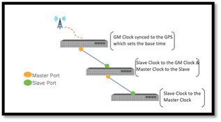
Figure 1: Master - Slave Architecture illustration
PTP messages are sent over the network using UDP, a protocol that provides low overhead. PTP uses a combination of unicast and multicast messages to synchronize the clocks in the network, as well as to detect and recover from network failures. PTP Master ports transmit Announce messages to the multicast address 224.0.1.129, which contains vital information to establish the synchronization hierarchy. The details within the PTP announce message play a crucial role in the BMCA (Best Master Clock Algorithm) for forming the synchronization hierarchy.
PTP also includes several advanced features, including support for multiple domains and a hierarchical architecture. These features provide additional flexibility and scalability for PTP, making it well suited for use in large and complex networks.
Best Master Clock Algorithm (BMCA):
BMCA is a simple algorithm that selects the best candidate clock in a PTP network. The selection process happens based on clock properties. The candidate with the best properties wins. The following properties are considering in the election process (in order of priority):
1. Priority1: A user assigned value (0-255) to designate absolute priority order amongst the clocks. Smaller value means higher priority.
2. Clock Quality:
a. Clock Class: It’s a non-configurable node priority value (6-255) assigned based on the frequency difference from the source. Smaller value means better class.
b. Class Accuracy: The accuracy (17-31 ns) of the clock compared to the UTC time. Smaller value means better accuracy.
c. Class Variance: Allan variance value that attributes to the stability of the clock. Smaller value means better precision.
3. Priority2: Another user assigned value to prioritize among clocks with identical clock qualities.
4. Clock Identity:
a. Clock Identity: User configurable 8-octet value to tie-break between identical priority and clock quality clocks.
b. Port Identity: Serves as a last comparison check for attributes from the same boundary clock’s different ports.
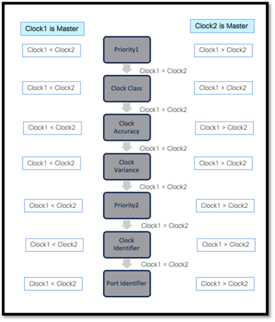
Figure 2: BMCA Master Clock selection process
The BMCA ensures that the most accurate clock with the lowest priority value is selected as the GM, which provides the most accurate time synchronization for the network.
The clock properties are advertised in the network through Announce messages. Only the current GM clock in a network sends Announce messages at a regular interval. If another clock in the PTP network considers itself a better master clock, it will transmit Announce messages to invoke a change of master clock. As the current master recognizes the better clock, it stops transmitting messages, and the better clock takes over as GM.
Basic mechanism behind PTP synchronization
PTP synchronization can be achieved through either one-step or two-step mode. These modes determine the number of message exchanges required to achieve synchronization between the master and the slave clocks.
1. One-Step Mode: In one-step mode, the synchronization process involves a single ‘Sync message’ exchange between the master clock and the slave clock. The master sends a PTP ‘Sync message’ to the slave which contains the timestamp of when the message is being sent out.
2. Two-Step Mode: In two-step mode, the synchronization process requires two message exchanges between the master and the slave clocks. First, the master sends a PTP ‘Sync message’ without a timestamp of when the message is being sent out to the slave. A ‘Follow up’ message which records the timestamp of when the ‘Sync message’ was sent to the slave needs to be sent separately.
While either of the modes do propagate the accurate timestamp of the sync message sent by the master, to correct the delay in the master clock due to the time taken in reading its clock and sending the message, devices cannot use different modes in the same network.
Nexus switches support two-step mode but is advisable to check the data sheet of the switch.
Once the master-slave hierarchy is established, the slave clock needs to synchronize its time with the master clock. For instance, suppose the master clock shows 00:00:01.02 seconds and the slave clock show 00:00:02.09 seconds, with a natural progression timeline for both clocks, the following 4-step process is followed to sync those two clocks.
Step 1. Sync message: The master clock sends a sync message to the slave clock. The sync message contains the timestamp of the master clock when the message was sent. When the slave clocks receive the sync message, they record the time they received the message.
The synchronization process begins with the master clock reading its time (1.02) and transmitting it to the slave clock with a sync message. The slave clock records the time set from GM in the sync message and the time when the sync message got received.
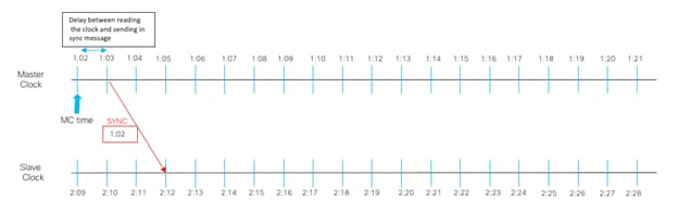
Figure 3: PTP Sync Message from master to slave
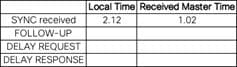
Figure 4: Slave clock time recordings
Step 2. Follow up: After recognizing the delay between reading its clock and sending the sync packet, the master sends a follow-up message to the slave with an updated timestamp indicating the exact time at which the initial sync packet was sent.
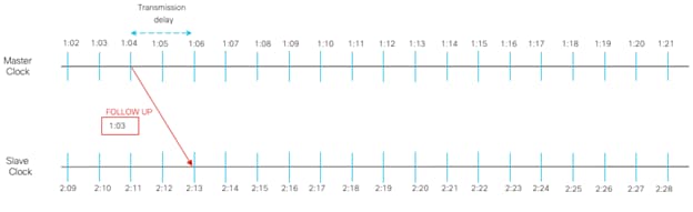
Figure 5: PTP Follow-Up Message
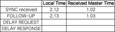
Figure 6: Slave clock time recordings after Follow-Up
Now the slave takes the difference between the local time and master time (1.02 – 2.12 = -1.10) and add to its current local time (2.13 – 1.10 = 1.03) and mark the slave time as 1.03.
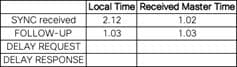
Figure 7: Slave time adjusts the time
The slave, however, recognizes that there is still a delay caused by the transmission time of the follow-up message from the master to the slave, which means that the master clock is different by the amount of time it takes for the message to be transmitted.
Step 3. Delay Request: Upon receiving an updated timestamp from the master via a follow-up message, the slave adjusts its time accordingly but notes a delay introduced by the transmission time of the message. To obtain a boomerang message with the master clock time, the slave sends a delay request to the master and notes the exact time that message was sent.
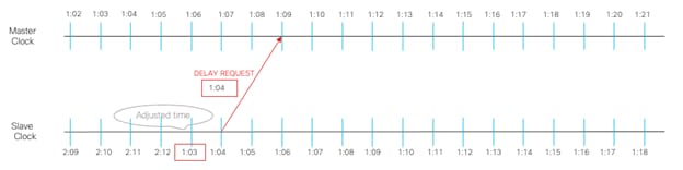
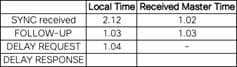
Figure 8: Slave records Delay Request sent time
Step 4. Delay Response: The master time stamps the arrival of the delay-request message and responds with a Delay Response message.
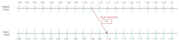
Figure 9: Delay Response message
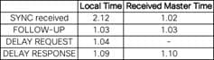
Figure 10: Recorded time of delay request responded by Master
The slave can calculate the round-trip transmission delay by subtracting the Delay Response stamped time by the master from the Delay Request time sent by the slave, and then dividing the result by 2 to account for the round-trip. For instance, ((1.09-1.04)/2 = .025s). The slave then corrects its time by adding the difference to its current time (1.10 + 0.025 = 1.125s)
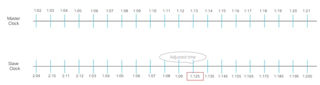
Figure 11: Final corrected time of the slave after 1st iteration of sync process
The synchronization process repeats on Nexus 9000 switches with a new sync message sent by default every 2 log seconds1 , continuously adjusting the clock to the nearest micro or nano-second correction
1In Cisco PTP (Precision Time Protocol), a log second refers to a unit of time measurement that is used to represent the frequency offset between two clocks. It is defined as the logarithm (base 2) of the ratio of the frequencies of the two clocks, multiplied by the duration of one second.
In other words, if two clocks have a frequency offset of f1/f2, where f1 is the frequency of one clock and f2 is the frequency of the other, then the log second value for this offset is given by:
log2(f1/f2) x 1 second
PTP Considerations and Design Options
Clock sources for PTP synchronization
PTP is a time synchronization mechanism that can be accomplished by utilizing a variety of clock sources. The quality of the clock source plays a vital role in achieving accurate synchronization using PTP. Several clock sources are available for PTP synchronization, for example:
GPS: Global Positioning System (GPS) is a satellite-based navigation system that provides accurate time information. GPS is one of the most common sources of clock used for PTP synchronization.
NTP (Network Time Protocol) server: NTP is a protocol used for synchronizing a device clock with a server over the network, can be used as a reference source of the time and provide for timekeeping in PTP networks.
IEEE 1588 Grandmaster Clock generators: An IEEE 1588 compliant device can generate the PTP signals and acts as the reference clock for the network.
In general, PTP can use any source of clock that provides accurate and reliable time information. The selection of the clock source depends on the specific requirements of the application and the environment in which it is used.
PTP GM Options
GPS synced PTP devices:
● Cisco Nexus 9000 FX3 switches have an onboarded GNSS receiver and a high-precision oscillator in the switch which is specifically designed to provide accurate and stable clock signals for time synchronization.
● Cisco Nexus GM Time Sync NIC is bundled with a GNSS receiver and equipped with configuration and management software that operates on any Linux host allowing it to run as a dedicated GM appliance.
● Non-Cisco NICs like the Intel XXV710-DA2T NIC with onboarded GPS receivers.
NTP synced PTP devices:
● Linux servers with NTP synced clocks.
● Any Cisco Nexus Cloud Scale ASIC-based2 switch that is configured to sync its clock with NTP can be used a GM. It is also recommended to use the Nexus-FX3 switches as a GM where available due to an enhanced oscillator.
There is a possible time drift between CPU clock and the Hardware clock in versions of NxOS before 10.2.4 and may require a re-sync of both the clocks (CSCvx49022).
Special Clock generators:
● Hardware master clock reference generators like Tektronix SPG8000A can be used as a GM.
Setting up PTP
Setting up PTP in your network is relatively straightforward and can be done in a few steps:
1. Determine the Master Clock: The first step in setting up PTP is to determine which device will act as the master clock. This should be a device that is reliable and has a high-precision clock. The master clock should also have a stable network connection to the other devices in the network. Then configure the GM clock, and other PTP-related setting to ensure its selection as the PTP GM.
2. Configure the Network: The next step is to configure the network to support PTP. This may involve configuring network switches, routers, and other devices to support PTP. For details please follow below guides based on the fabric:
NXOS Configuration guide:
NDFC Configuration guide:
ACI Configuration guide:
3. Monitor the time synchronization after the PTP network is set up, you can monitor the accuracy of time synchronization using PTP monitoring tool on NDFC or on the switches directly.
PTP GM options in a single-site environment
In Figure 12, Different options of PTP GMs and their recommended positioning in the network are shown.
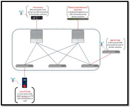
Figure 12: Different options of GM and their placements
Note: The above options is not illustration of a need for different types of GM. Its merely to depict different GM options and illustrate its placement and ability to chose one of the preferred options.
As shown in Figure 12, user could choose one type of GM or combine multiple GM types for redundancy. As discussed in previous sections, Cisco Nexus 9000 switch can be nominated as a GM although is not recommended as it does not have a dedicated hardware to act as an ideal GM (with the exception of a model of FX3 switch) which may result in a potential drift between its CPU clock and hardware clock. If this is the case, it is advisable to dedicate it to this function and exclude it from the fabric.
As a general recommendation, to prevent network nodes from losing synchronization if a single master clock fails to receive time synchronization from its source or goes offline, a redundant master clock is recommended. This ensures that all network node clocks remain synchronized even if the primary clock fails. The Best Master Clock Algorithm (BMCA) automatically selects the ideal GM and ensures a smooth backup takeover in case of primary clock failure. Therefore, manual intervention is not necessary.
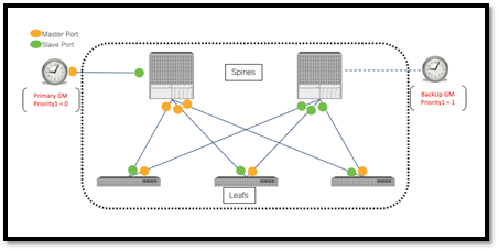
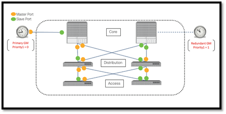
Figure 13: PTP Primary and Redundant GM in Leaf/Spine and Classic LAN architecture
Note: Both the example architectures assume PTP Boundary Clock(BC) roles for all nodes
PTP GM options in a multi-pod environment
To optimize the PTP's hierarchical tree structure of master and slave ports in a multi-pod setup, it is advisable to connect the GMs to the SS/IPNs. This helps to form the center of the tree, reducing the number of hops and distance to the last slave node of each branch. Figure14, shows recommended GM position in a multi-pod environment.
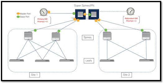
Figure 14: Multi-Pod common redundant GM pair connected to SS/IPN
The BMCA algorithm chooses the master and slave ports in both sites similar to Figure13, but this is not illustrated in figure14
Furthermore, if any of the SS/IPNs happen to be Nexus 9000 FX3 switches and stitching across the fabric is not required, they can serve as PTP GMs by configuring the correct priority on the desired FX3 switch. It is crucial to set the priority correctly to ensure that the chosen FX3 switch becomes the GM.
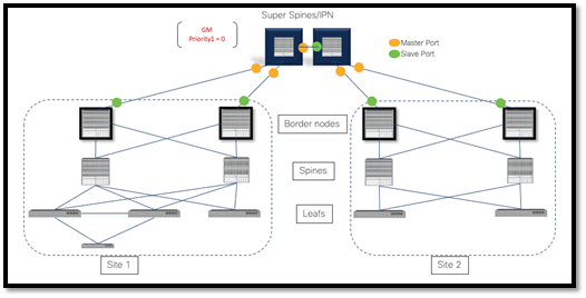
Figure 15: Multi-Pod SS/IPN acting as PTP GM
The BMCA algorithm chooses the master and slave ports in both sites similar to Figure13, but this is not illustrated in figure15
PTP GM options in a multi-site environment
In a multi-site setup with congruent Router Servers/IPNs/Core Routers, it is recommended to connect the GM to these devices for better connectivity.
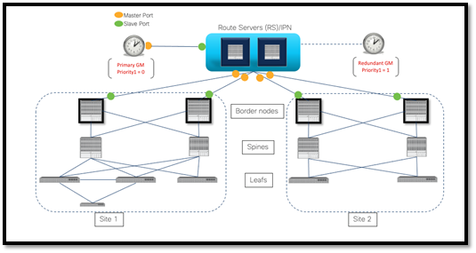
Figure 16: Multi-site common redundant GM pair connected to the core.
The BMCA algorithm chooses the master and slave ports in both sites similar to Figure13, but this is not illustrated in figure16
If N9000 FX3 switches are used as Route Servers/IPNs, they can act as PTP GMs without the need of dedicated external GMs. However, if a mix of FX3 and non-FX3 switches make up the RS/IPN devices, it is advisable to assign a lower PTP priority1 to the FX3 switch selected as the PTP GM. This ensures that the BMCA does not select a non-FX3 switch as the PTP GM.
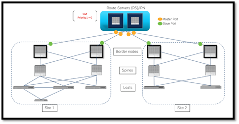
Figure 17: Multi-Site RS/IPN acting as PTP GM
The BMCA algorithm chooses the master and slave ports in both sites similar to Figure13, but this is not illustrated in figure17
If the RS/IPN topology is more complicated and it is not possible to ensure that the latency between the RS/IPN devices and the sites is the same everywhere, it is recommended to use a GM per site preferably connected to the same reference time source to circumvent the delay of time sync from the GM in one site to the other.
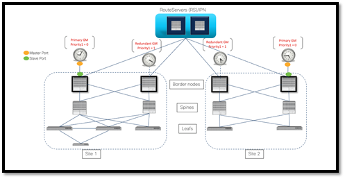
Figure 18: Multi-site redundant GM pair in each site.
The BMCA algorithm chooses the master and slave ports in both sites similar to Figure13, but this is not illustrated in figure16
Note: The same theory applies even if a NIC(h/w)/Linux(s/w) based GMs are used and connected to the Leaf/Access/Distribution layers.
In multisite environments where there is no PTP GM redundancy per site, its preferable to use a PTP feeder switch to avoid loss of connection to the primary GM.
PTP is not only essential for achieving time precision and obtaining an end-to-end network view when streaming telemetry data from network nodes, but it is also crucial for modern applications used in various industries such as media, financial trading, and telecom. The implementation of PTP enhances accuracy in time synchronization for both network and application nodes. It also establishes a standardized approach to time synchronization, ensuring consistency and reliability throughout the system.