Configuring Port VLAN Mapping

This chapter contains these sections:

About Translating Incoming VLANs

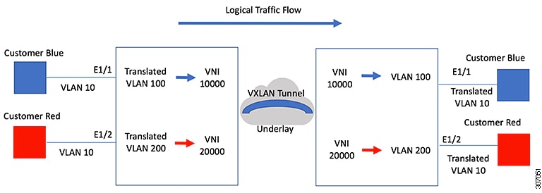
Sometimes a VLAN translation is required or desired. One such use case is when a service provider has multiple customers connecting to the same physical switch using the same VLAN encapsulation, but they are not and should not be on the same Layer 2 segment. In such cases translating the incoming VLAN to a unique VLAN that is then mapped to a VNI is the right way to extending the segment. In the figure below two customers, Blue and Red are both connecting to the leaf using VLAN 10 as their encapsulation.

Customers Blue and Red should not be on the same VNI. In this example VLAN 10 for Customer Blue (on interface E1/1) is mapped/translated to VLAN 100, and VLAN 10 for customer Red (on interface E1/2) is mapped to VLAN 200. In turn, VLAN 100 is mapped to VNI 10000 and VLAN 200 is mapped to VNI 20000.

On the other leaf, this mapping is applied in reverse. Incoming VXLAN encapsulated traffic on VNI 10000 is mapped to VLAN 100 which in turn is mapped to VLAN 10 on Interface E1/1. VXLAN encapsulated traffic on VNI 20000 is mapped to VLAN 200 which in turn is mapped to VLAN 10 on Interface E1/2.

Figure 1. Logical Traffic Flow
Logical Traffic Flow

You can configure VLAN translation between the ingress (incoming) VLAN and a local (translated) VLAN on a port. For the traffic arriving on the interface where VLAN translation is enabled, the incoming VLAN is mapped to a translated VLAN that is VXLAN enabled.

On the underlay, this is mapped to a VNI, the inner dot1q is deleted, and switched over to the VXLAN network. On the egress switch, the VNI is mapped to a translated VLAN. On the outgoing interface, where VLAN translation is configured, the traffic is converted to the original VLAN and egressed out. Refer to the VLAN counters on the translated VLAN for the traffic counters and not on the ingress VLAN. Port VLAN (PV) mapping is an access side feature and is supported with both multicast and ingress replication for flood and learn and MP-BGP EVPN mode for VXLAN.

Guidelines and Limitations for Port VLAN Mapping

The following are the guidelines and Limitations for Port VLAN Mapping:

  • Support is added for vPC Fabric Peering.

  • Beginning with Cisco NX-OS Release 10.3(3)F, VLAN translation is supported on both VXLAN and non-VXLAN VLANs.

  • The ingress (incoming) VLAN does not need to be configured on the switch as a VLAN. The translated VLAN needs to be configured and a vn-segment mapping given to it. An NVE interface with VNI mapping is essential for the same.

  • All Layer 2 source address learning and Layer 2 MAC destination lookup occurs on the translated VLAN. Refer to the VLAN counters on the translated VLAN and not on the ingress (incoming) VLAN.

  • Cisco Nexus 9300 and 9500 switches support switching and routing on overlapped VLAN interfaces. Only VLAN-mapping switching is applicable for Cisco Nexus 9300-EX/FX/FX2/FX3 platform switches and Cisco Nexus 9500 with -EX/FX line cards.

  • Port VLAN routing is supported on the following platforms:

    • Beginning with Cisco NX-OS Release 7.x, this feature is supported on Cisco Nexus 9300-EX/FX/FX2 platform switches.

    • Beginning with Cisco NX-OS Release 9.2(x), this feature is supported on Cisco Nexus 9300-GX platform switches.

    • Beginning with Cisco NX-OS Release 9.3(x), this feature is supported on Cisco Nexus 9300-FX3 platform switches.

    • Beginning with Cisco NX-OS Release 10.2(3)F, this feature is supported on the Cisco Nexus 9300-GX2 platform switches.

  • Beginning with Cisco NX-OS Release 9.3(3), PV Translation is supported for Cisco Nexus 9300-GX platform switches.

  • Beginning with Cisco NX-OS Release 10.2(3)F, PV Translation is supported on the Cisco Nexus 9300-GX2 platform switches.

  • On Cisco Nexus 9300 Series switches with NFE ASIC, PV routing is not supported on 40 G ALE ports.

  • PV routing supports configuring an SVI on the translated VLAN for flood and learn and BGP EVPN mode for VXLAN.

  • VLAN translation (mapping) is supported on Cisco Nexus 9000 Series switches with a Network Forwarding Engine (NFE).

  • When changing a property on a translated VLAN, the port that has a mapping configuration with that VLAN as the translated VLAN, must be flapped to ensure correct behavior. This is applicable only to the following platforms:

    • N9K-C9504 modules

    • N9K-C9508 modules

    • N9K-C9516 modules

    • Nexus 9400 line cards

    • Nexus 9500 line cards

    • Nexus 9600 line cards

    • Nexus 9700-X Cloud Scale line cards

    • Nexus 9600-R and R2 line cards

    Int eth 1/1
    switchport vlan mapping 101 10
    .
    .
    .
     
    /***Deleting vn-segment from vlan 10.***/
    /***Adding vn-segment back.***/
    /***Flap Eth 1/1 to ensure correct behavior.***/
  • The following example shows incoming VLAN 10 being mapped to local VLAN 100. Local VLAN 100 will be the one mapped to a VXLAN VNI.

    interface ethernet1/1
    switchport vlan mapping 10 100
  • The following is an example of overlapping VLAN for PV translation. In the first statement, VLAN-102 is a translated VLAN with VNI mapping. In the second statement, VLAN-102 the VLAN where it is translated to VLAN-103 with VNI mapping.

    interface ethernet1/1
    switchport vlan mapping 101 102
    switchport vlan mapping 102 103/
  • When adding a member to an existing port channel using the force command, the "mapping enable" configuration must be consistent. For example:

    Int po 101
    switchport vlan mapping enable
    switchport vlan mapping 101 10
    switchport trunk allowed vlan 10
     
    int eth 1/8
    /***No configuration***/

    Note


    The switchport vlan mapping enable command is supported only when the port mode is trunk.


  • Port VLAN mapping is not supported on Cisco Nexus 9200 platform switches.

  • VLAN mapping helps with VLAN localization to a port, scoping the VLANs per port. A typical use case is in the service provider environment where the service provider leaf switch has different customers with overlapping VLANs that come in on different ports. For example, customer A has VLAN 10 coming in on Eth 1/1 and customer B has VLAN 10 coming in on Eth 2/2.

    In this scenario, you can map the customer VLAN to a provider VLAN and map that to a Layer 2 VNI. There is an operational benefit in terminating different customer VLANs and mapping them to the fabric-managed VLANs, L2 VNIs.

  • An NVE interface with VNI mapping must be configured for Port VLAN translation to work.

  • You should not enable super bridging VLAN in the provider VLAN list of the system dot1q-tunnel transit vlan <id> command. If enabled it will end up in unrecoverable functional and forwarding impacts.

  • Port VLAN mapping is not supported on FEX ports.

  • Beginning with Cisco NX-OS Release 10.3(3)F, IPv6 underlay is supported on Port VLAN Mapping for VXLAN EVPN on Cisco Nexus 9300-EX/FX/FX2/FX3/GX/GX2 switches and Cisco Nexus 9500 switches with 9700-EX/FX/GX line cards.

Configuring Port VLAN Mapping on a Trunk Port

Before you begin

  • Ensure that the physical or port channel on which you want to implement VLAN translation is configured as a Layer 2 trunk port.

  • Ensure that the translated VLANs are created on the switch and are also added to the Layer 2 trunk ports trunk-allowed VLAN vlan-list.


    Note


    As a best practice, do not add the ingress VLAN ID to the switchport allowed vlan-list under the interface.


  • Ensure that all translated VLANs are VXLAN enabled.

SUMMARY STEPS

  1. configure terminal
  2. interface type/port
  3. [no] switchport vlan mapping enable
  4. [no] switchport vlan mapping vlan-id translated-vlan-id
  5. [no] switchport vlan mapping all
  6. copy running-config startup-config
  7. show interface [if-identifier] vlan mapping

DETAILED STEPS

  Command or Action Purpose

Step 1

configure terminal

Example:

switch# configure terminal

Enters global configuration mode.

Step 2

interface type/port

Example:

switch(config)# interface Ethernet1/1

Specifies the interface that you are configuring.

Step 3

[no] switchport vlan mapping enable

Example:

switch(config-if)# [no] switchport vlan mapping enable

Enables VLAN translation on the switch port. VLAN translation is disabled by default.

Note


Use the no form of this command to disable VLAN translation.

Step 4

[no] switchport vlan mapping vlan-id translated-vlan-id

Example:

switch(config-if)# switchport vlan mapping 10 100

Translates a VLAN to another VLAN.

  • The range for both the vlan-id and translated-vlan-id arguments are from 1 to 4094.

  • You can configure VLAN translation between the ingress (incoming) VLAN and a local (translated) VLAN on a port. For the traffic arriving on the interface where VLAN translation is enabled, the incoming VLAN is mapped to a translated VLAN that is VXLAN enabled.

On the underlay, this is mapped to a VNI, the inner dot1q is deleted, and switched over to the VXLAN network. On the egress switch, the VNI is mapped to a local translated VLAN. On the outgoing interface, where VLAN translation is configured, the traffic is converted to the original VLAN and egresses out.

Note


Use the no form of this command to clear the mappings between a pair of VLANs.

Step 5

[no] switchport vlan mapping all

Example:

switch(config-if)# switchport vlan mapping all

Removes all VLAN mappings configured on the interface.

Step 6

copy running-config startup-config

Example:

switch(config-if)# copy running-config startup-config

Copies the running configuration to the startup configuration.

Note


The VLAN translation configuration does not become effective until the switch port becomes an operational trunk port.

Step 7

show interface [if-identifier] vlan mapping

Example:

switch# show interface ethernet1/1 vlan mapping

Displays VLAN mapping information for a range of interfaces or for a specific interface.

Example

This example shows how to configure VLAN translation between (the ingress) VLAN 10 and (the local) VLAN 100. The show vlan counters command output shows the statistic counters as translated VLAN instead of customer VLAN.

switch#  configure terminal 
switch(config)#  interface ethernet1/1   
switch(config-if)#  switchport vlan mapping enable 
switch(config-if)#  switchport vlan mapping 10 100  
switch(config-if)#  switchport trunk allowed vlan 100 
switch(config-if)#  show interface ethernet1/1 vlan mapping 
Interface eth1/1:
Original VLAN           Translated VLAN
------------------      ---------------
10                           100  
 
switch(config-if)#  show vlan counters 
Vlan Id                             :100
Unicast Octets In                   :292442462  
Unicast Packets In                  :1950525  
Multicast Octets In                 :14619624  
Multicast Packets In                :91088  
Broadcast Octets In                 :14619624  
Broadcast Packets In                :91088  
Unicast Octets Out                  :304012656  
Unicast Packets Out                 :2061976  
L3 Unicast Octets In                :0  
L3 Unicast Packets In               :0 

Configuring Inner VLAN and Outer VLAN Mapping on a Trunk Port

Configuring Inner VLAN and Outer VLAN Mapping on a Trunk Port is applicable only for Cisco Nexus 9300 platforms and not supported on Cisco Nexus 9200, 9300-EX, 9300-FX, 9300-FX2, 9300-FX3, 9300-GX, 9300-GX2, 9364C, 9332C platforms.

You can configure VLAN translation from an inner VLAN and an outer VLAN to a local (translated) VLAN on a port. For the double tag VLAN traffic arriving on the interfaces where VLAN translation is enabled, the inner VLAN and outer VLAN are mapped to a translated VLAN that is VXLAN enabled.

Notes for configuring inner VLAN and outer VLAN mapping:

  • Inner and outer VLAN cannot be on the trunk allowed list on a port where inner VLAN and outer VLAN is configured.

    For example:

    
    switchport vlan mapping 11 inner 12 111
    switchport trunk allowed vlan 11-12,111 /***Not valid because 11 is outer VLAN and 12 is inner VLAN.***/ 
    
    
  • On the same port, no two mapping (translation) configurations can have the same outer (or original) or translated VLAN. Multiple inner VLAN and outer VLAN mapping configurations can have the same inner VLAN.

    For example:

     
    switchport vlan mapping 101 inner 102 1001
    switchport vlan mapping 101 inner 103 1002  /***Not valid because 101 is already used as an original VLAN.***/
    switchport vlan mapping 111 inner 104 1001  /***Not valid because 1001 is already used as a translated VLAN.***/
    switchport vlan mapping 106 inner 102 1003  /***Valid because inner vlan can be the same.***/ 
    
  • When a packet comes double-tagged on a port which is enabled with the inner option, only bridging is supported.

  • VXLAN PV routing is not supported for double-tagged frames.

SUMMARY STEPS

  1. configure terminal
  2. interface type port
  3. [no] switchport mode trunk
  4. switchport vlan mapping enable
  5. switchport vlan mapping outer-vlan-id inner inner-vlan-id translated-vlan-id
  6. (Optional) copy running-config startup-config
  7. (Optional) show interface [if-identifier] vlan mapping

DETAILED STEPS

  Command or Action Purpose

Step 1

configure terminal

Enters global configuration mode.

Step 2

interface type port

Enters interface configuration mode.

Step 3

[no] switchport mode trunk

Enters trunk configuration mode.

Step 4

switchport vlan mapping enable

Enables VLAN translation on the switch port. VLAN translation is disabled by default.

Note


Use theno form of this command to disable VLAN translation.

Step 5

switchport vlan mapping outer-vlan-id inner inner-vlan-id translated-vlan-id

Translates inner VLAN and outer VLAN to another VLAN.

Step 6

(Optional) copy running-config startup-config

(Optional)

Copies the running configuration to the startup configuration.

Note


The VLAN translation configuration does not become effective until the switch port becomes an operational trunk port

Step 7

(Optional) show interface [if-identifier] vlan mapping

(Optional)

Displays VLAN mapping information for a range of interfaces or for a specific interface.

Example

This example shows how to configure translation of double tag VLAN traffic (inner VLAN 12; outer VLAN 11) to VLAN 111.


switch# configure terminal
switch(config)# interface ethernet1/1
switch(config-if)# switchport mode trunk
switch(config-if)# switchport vlan mapping enable 
switch(config-if)# switchport vlan mapping 11 inner 12 111  
switch(config-if)# switchport trunk allowed vlan 101-170
switch(config-if)# no shutdown

switch(config-if)# show mac address-table dynamic vlan 111

Legend: 
        * - primary entry, G - Gateway MAC, (R) - Routed MAC, O - Overlay MAC
        age - seconds since last seen,+ - primary entry using vPC Peer-Link,
        (T) - True, (F) - False
   VLAN     MAC Address      Type      age     Secure NTFY Ports
---------+-----------------+--------+---------+------+----+------------------
*  111     0000.0092.0001   dynamic  0         F      F    nve1(100.100.100.254)
*  111     0000.0940.0001   dynamic  0         F      F    Eth1/1

About Port Multi-VLAN Mapping

With Port Multi-VLAN Mapping feature multiple VLANs are mapped on a trunk interface to a single global VLAN/VNI. Layer 2 (L2) sub-interface has to be created for the mapping and a qTag has to be provided for each L2 sub-interface.

Different Port-VLANs can serve different services on the same physical interface.

For the Port Multi-VLAN mappings per trunk port, ACLs are installed per each of the mapping using L2 sub-interface. Some ACLs are installed automatically by default and some are installed with static MAC address configuration. L2 sub-interface has a qtag, flood-domain or provider-VLAN. The provider-VLAN is configured on the switch and is used for traffic forwarding. There can be only one provider-VLAN on the switch.

This static MAC configuration is done using the switchport mac-address static-only command configured on L2 sub-interface parent port. This command disables the MAC learning on the parent port and enables MAC-ACL per each static MAC configured on the L2 sub-interfaces.

Guidelines and Limitations for Port Multi-VLAN Mapping

The following are the guidelines and limitations for Port Multi-VLAN Mapping:

  • Beginning with Cisco NX-OS Release 10.2(3)F, the Port Multi-VLAN feature is supported on N9K-C9316D-GX, N9K-C93600CD-GX, N9K-C9364C-GX, and Cisco Nexus 9300-GX2 switches.

  • Beginning with Cisco NX-OS Release 10.1(2), Port Multi-VLAN Mapping is supported on Cisco Nexus 9300-EX, FX, and FX2 platform switches.

  • Beginning with Cisco NX-OS Release 10.2(3)F, Port Multi-VLAN Mapping is supported on the Cisco Nexus 9300-FX3 platform switches.

  • Port Multi-VLAN Mapping is an access side feature and is supported with both multicast and ingress replication for VXLAN flood and learn mode. This feature is not supported for VXLAN MP-BGP EVPN mode in Cisco NX-OS Release 10.1(2).

  • For a device that is running on Cisco Nexus Release 10.1(2) or Cisco Nexus Release 10.2(1)F ND-ISSU is not supported if L2 sub-interfaces are configured.

  • This feature is not supported with vPC fabric peering configuration.

  • In order to protect against broadcast or multicast flood, all flooding traffic is dropped except ARP and NS/ND.

  • Layer 2 is supported.

  • STP is not supported.

  • Static default route or specific route to remote VTEP is recommended to be configured on ToRs.

  • Interaction with other access features like QinQ/QinVNI, Port VLAN mapping, PVLAN and Xconnect are not supported.

The following are the guidelines and limitations related to the parent interface:

  • TCAM entries are only installed on the slice where the parent port exists. To check TCAM utilization, use the show system internal access-list resource utilization command.

  • To check the port slice, use the show interface hardware-mappings command.

  • For hosts using static ARP, add on ToR static MAC entry for remote host on interface nve 1. Example:

     mac address-table static 0034.0100.0001 vni 10013001 interface nve 1 peer-ip 192.168.75.2
  • Port-security/dot1x is not supported on the parent interface.

  • vPC mode is not supported for parent interface or L2 sub interface.

The following are the guidelines and limitations related to the sub interface:

  • Maximum of 510 sub-interfaces are supported per switch.

  • ACL and storm-control per sub-interface cannot be configured under the switch port mapping.

  • TCAM region must be re-configured in order to support Max 510 L2 sub interfaces. For each L2 sub interface nine TCAM ing-pacl-sb entries are allocated.

  • Static MAC is configured on L2 sub interface using the switchport mac-address static-only command on the parent interface.

  • L2 sub interfaces are not supported without VXLAN deployment. The provider VLAN must be a VXLAN VLAN.

  • Dynamic MAC learning is disabled on L2 sub interface.

  • Storm control is not supported for L2 sub interface.

  • The hardware profile svi-and-si flex-stats-enable command supports only ingress L2 sub interface counters. This profile statistics command does not support egress L2 sub interface counters and VxLAN statistics.

  • IGMP snooping is not supported on the provider VLAN where L2 sub interface is configured.

Configuring Port Multi-VLAN Mapping

A sample configuration of Port Multi-VLAN Mapping is provided below:

feature ospf
feature pim
feature bfd
feature interface-vlan
feature vn-segment-vlan-based
feature private-vlan
feature lacp
feature nv overlay

hardware access-list tcam region ing-pacl-sb 2560
hardware profile svi-and-si flex-stats-enable

ip pim rp-address 2.0.0.254 group-list 224.0.0.0/4

vlan 3001
  vn-segment 10013001

interface Ethernet1/22
  switchport
  switchport mode trunk
  switchport trunk allowed vlan 3001
  mtu 9216
  storm-control broadcast level 0.01
  storm-control action trap
  switchport isolated
  switchport mac-address static-only
  no shutdown

interface Ethernet1/22.1
  encapsulation dot1q 301 provider-vlan 3001
  no shutdown

interface Ethernet1/22.2
  encapsulation dot1q 302 provider-vlan 3001
  no shutdown

interface Ethernet1/22.3
  encapsulation dot1q 303 provider-vlan 3001
  no shutdown

interface Ethernet1/22.4
  encapsulation dot1q 304 provider-vlan 3001
  no shutdown

interface Ethernet1/22.5
  encapsulation dot1q 305 provider-vlan 3001
  no shutdown

interface port-channel1
  switchport
  switchport mode trunk
  switchport trunk allowed vlan 3001
  mtu 9216
  storm-control broadcast level 0.01
  storm-control multicast level 0.01
  storm-control unicast level 0.01
  storm-control action trap
  switchport isolated
  switchport mac-address static-only

interface port-channel1.1
  encapsulation dot1q 301 provider-vlan 3001
  no shutdown

interface port-channel1.2
  encapsulation dot1q 302 provider-vlan 3001
  no shutdown

interface port-channel1.3
  encapsulation dot1q 303 provider-vlan 3001
  no shutdown

interface port-channel1.4
  encapsulation dot1q 304 provider-vlan 3001
  no shutdown

interface port-channel1.5
  encapsulation dot1q 305 provider-vlan 3001
  no shutdown

interface Ethernet1/24
  switchport
  switchport mode trunk
  switchport trunk allowed vlan 3001
  mtu 9216
  storm-control broadcast level 0.01
  storm-control multicast level 0.01
  storm-control unicast level 0.01
  storm-control action trap
  switchport isolated
  switchport mac-address static-only
  channel-group 1 mode active
  no shutdown

interface Ethernet1/25
  switchport
  switchport mode trunk
  switchport trunk allowed vlan 3001
  mtu 9216
  storm-control broadcast level 0.01
  storm-control multicast level 0.01
  storm-control unicast level 0.01
  storm-control action trap
  switchport isolated
  switchport mac-address static-only
  channel-group 1 mode active
  no shutdown

mac address-table static 0035.0100.0001 vlan 3001 interface Ethernet1/22.1
mac address-table static 0035.0100.0002 vlan 3001 interface Ethernet1/22.2
mac address-table static 0035.0100.0003 vlan 3001 interface Ethernet1/22.3
mac address-table static 0035.0100.0004 vlan 3001 interface Ethernet1/22.4
mac address-table static 0035.0100.0005 vlan 3001 interface Ethernet1/22.5

mac address-table static 003b.0100.0001 vlan 3001 interface port-channel1.1
mac address-table static 003b.0100.0002 vlan 3001 interface port-channel1.2
mac address-table static 003b.0100.0003 vlan 3001 interface port-channel1.3
mac address-table static 003b.0100.0004 vlan 3001 interface port-channel1.4
mac address-table static 003b.0100.0005 vlan 3001 interface port-channel1.5


router ospf p1
  bfd
  router-id 192.168.210.1

interface loopback0
  ip address 192.168.210.1/32
  ip router ospf p1 area 0.0.0.0
  ip pim sparse-mode

interface loopback1
  description NVE_IP
  ip address 192.168.210.2/32
  ip router ospf p1 area 0.0.0.0
  ip pim sparse-mode

interface Ethernet1/49
  mtu 9216
  no ip redirects
  ip address 10.0.1.16/31
  ip router ospf p1 area 0.0.0.0
  ip pim sparse-mode
  no shutdown

interface Ethernet1/54
  mtu 9216
  no ip redirects
  ip address 10.0.1.18/31
  ip router ospf p1 area 0.0.0.0
  ip pim sparse-mode
  no shutdown

interface nve1
  no shutdown
  source-interface loopback1
 member vni 10013001
    mcast-group 227.1.1.1

The following examples provide show command outputs related to Port Multi-VLAN Mapping:

switch# show hardware access-list resource utilization | grep Super

Ingress PACL Super Bridge               2445    115     95.50
 Ingress PACL Super Bridge IPv4         0               0.00
 Ingress PACL Super Bridge IPv6         0               0.00
 Ingress PACL Super Bridge MAC          0               0.00
 Ingress PACL Super Bridge ALL          1956            76.40
 Ingress PACL Super Bridge OTHER        489             19.10

switch # show hardware access-list resource entries | in Super

Ingress PACL Super Bridge                : 2445 valid entries   115 free entries

switch# show interface ethernet 1/22.1-5 brief
--------------------------------------------------------------------------------
Ethernet        VLAN    Type Mode   Status  Reason                 Speed     Port
Interface                                                                    Ch #
--------------------------------------------------------------------------------
Eth1/22.1       301     eth  trunk  up      none                      10G(D) --
Eth1/22.2       302     eth  trunk  up      none                      10G(D) --
Eth1/22.3       303     eth  trunk  up      none                      10G(D) --
Eth1/22.4       304     eth  trunk  up      none                      10G(D) --
Eth1/22.5       305     eth  trunk  up      none                      10G(D) --


switch# show interface port-channel 1.1-5 brief
------------------------------------------------------------------------------------------
Port-channel VLAN    Type Mode   Status  Reason     Speed   Protocol
Interface
------------------------------------------------------------------------------------------
Po1.1        301     eth  trunk  up      none        a-10G(D)    --
Po1.2        302     eth  trunk  up      none        a-10G(D)    --
Po1.3        303     eth  trunk  up      none        a-10G(D)    --
Po1.4        304     eth  trunk  up      none        a-10G(D)    --
Po1.5        305     eth  trunk  up      none        a-10G(D)    --

switch# show interface ethernet 1/22.1 counters

----------------------------------------------------------------------------------
Port                                     InOctets                      InUcastPkts
----------------------------------------------------------------------------------
Eth1/22.1                           1145503766466                        125246421

----------------------------------------------------------------------------------
Port                                  InMcastPkts                      InBcastPkts
----------------------------------------------------------------------------------
Eth1/22.1                                       0                                0

----------------------------------------------------------------------------------
Port                                    OutOctets                     OutUcastPkts
----------------------------------------------------------------------------------
Eth1/22.1                                       0                                0

----------------------------------------------------------------------------------
Port                                 OutMcastPkts                     OutBcastPkts
----------------------------------------------------------------------------------
Eth1/22.1                                       0                                0

switch# show consistency-checker l2 sub-interface port-channel 1.1

Getting details for port-channel1.1 (0x16001000)
=========================================
Running CC for port-channel1.1
=========================================
CC for Permit Static: PASSED
CC for Deny ACL: PASSED
CC for Permit ARP ACL: PASSED
CC for Permit Multi-Dest ACL: PASSED
CC for info_src_idx: PASSED
CC for info_bd_xlate_idx: PASSED
CC for info_vlan_mbr_chk_bypasss: PASSED
CC for info_set_dont_learn: PASSED
CC for VlanXlate Table: PASSED
CC for BD State Table: PASSED
CC for QSMT BD State Table: PASSED
CC for Local Multipath Table: PASSED
CC for Rw VifTable: PASSED
CC for Rwx VlanXlate Table: PASSED


switch# show system internal access-list interface eth 1/22.1

slot 1
=======

Policies in ingress direction:
Policy type Policy Id Policy name
------------------------------------------------------------
PACL Super Bridge 341 l2fm-acl-mac-Eth1/22.1
PACL Super Bridge 342 l2fm-acl-ipv6-Eth1/22.1

No Netflow profiles in ingress direction

INSTANCE 0x0
---------------

Tcam 20 resource usage:
----------------------
LBL AB = 0x11
Bank 0
------
IPv6 Class
Policies: PACL Super Bridge(l2fm-acl-ipv6-Eth1/22.1)
Netflow profile: 0
Netflow deny profile: 0
2 tcam entries
MAC Class
Policies: PACL Super Bridge(l2fm-acl-mac-Eth1/22.1)
Netflow profile: 0
Netflow deny profile: 0
3 tcam entries

0 l4 protocol cam entries
0 mac etype/proto cam entries
0 lous
0 tcp flags table entries
0 adjacency entries

No egress policies
No Netflow profiles in egress direction


switch# show system internal access-list interface eth 1/22.1 input statistics

slot 1
=======
INSTANCE 0x0
---------------

Tcam 20 resource usage:
----------------------
LBL AB = 0xb
Bank 0
------
IPv6 Class
Policies: PACL Super Bridge(l2fm-acl-ipv6-Eth1/22.1)
Netflow profile: 0
Netflow deny profile: 0
Entries:
[Index] Entry [Stats]
---------------------
[0x0038:0x0038:0x0038] permit lbl(0x0) 0000.0000.0000 ffff.ffff.ffff 0000.0000.0000 ffff.ffff.ffff vlan 502 [9]
[0x003a:0x003a:0x003a] permit lbl(0x0) 0000.0000.0000 ffff.ffff.ffff 0000.0000.0000 ffff.ffff.ffff vlan 502 [0]
MAC Class
Policies: PACL Super Bridge(l2fm-acl-mac-Eth1/22.1)
Netflow profile: 0
Netflow deny profile: 0
Entries:
[Index] Entry [Stats]
---------------------
[0x003c:0x003c:0x003c] permit lbl(0x0) arp [7]
[0x003d:0x08de:0x08de] permit lbl(0x0) 0035.0100.0001 ffff.ffff.ffff 0000.0000.0000 ffff.ffff.ffff vlan 502 [6279856]
[0x08dd:0x08e0:0x08e0] deny lbl(0x0) 0000.0000.0000 ffff.ffff.ffff 0000.0000.0000 ffff.ffff.ffff vlan 502 [279]