Cisco Cloud Network Controller Policy Model

About the CCNC Policy Model

The CCNC policy model enables the specification of application requirements policies. The Cisco Cloud Network Controller automatically renders policies in the cloud infrastructure. When you or a process initiates an administrative change to an object in the cloud infrastructure, the Cisco Cloud Network Controller first applies that change to the policy model. This policy model change then triggers a change to the actual managed item. This approach is called a model-driven framework.

Policy Model Key Characteristics

Key characteristics of the policy model include the following:

  • As a model-driven architecture, the software maintains a complete representation of the administrative and operational state of the system (the model). The model applies uniformly to cloud infrastructure, cloud infrastructure, services, system behaviors, and virtual devices attached to the network.

  • The logical and concrete domains are separated; the logical configurations are rendered into concrete configurations by applying the policies in relation to the available resources. No configuration is carried out against concrete entities. Concrete entities are configured implicitly as a side effect of the changes to the Cisco Cloud policy model.

  • The system prohibits communications with newly connected endpoints until the policy model is updated to include the new endpoint.

  • Network administrators do not configure logical system resources directly. Instead, they define logical (hardware-independent) configurations and the Cisco Cloud Network Controller policies that control different aspects of the system behavior.

Managed object manipulation in the model relieves engineers from the task of administering isolated, individual component configurations. These characteristics enable automation and flexible workload provisioning that can locate any workload anywhere in the infrastructure. Network-attached services can be easily deployed, and the Cisco Cloud Network Controller provides an automation framework to manage the lifecycle of those network-attached services.

Logical Constructs

The policy model manages the entire cloud infrastructure, including the infrastructure, authentication, security, services, applications, cloud infrastructure, and diagnostics. Logical constructs in the policy model define how the cloud infrastructure meets the needs of any of the functions of the cloud infrastructure. The following figure provides an overview of the CCNC policy model logical constructs.
Figure 1. CCNC Policy Model Logical Constructs Overview

Certain administrators (tenant or cloud infrastructure-wide) create predefined policies that contain application or shared resource requirements. These policies automate the provisioning of applications, network-attached services, security policies, and tenant subnets, which puts administrators in the position of approaching the resource pool in terms of applications rather than infrastructure building blocks. The application needs to drive the networking behavior, not the other way around.

The CCNC Policy Management Information Model

The cloud infrastructure comprises the logical components as recorded in the Management Information Model (MIM), which can be represented in a hierarchical management information tree (MIT). The Cisco Cloud Network Controller runs processes that store and manage the information model. Similar to the OSI Common Management Information Protocol (CMIP) and other X.500 variants, the Cisco Cloud Network Controller enables the control of managed resources by presenting their manageable characteristics as object properties that can be inherited according to the location of the object within the hierarchical structure of the MIT.

Each node in the tree represents a managed object (MO) or group of objects. MOs are abstractions of cloud infrastructure resources. An MO can represent a concrete object, such as a cloud router, adapter, or a logical object, such as an application profile, cloud endpoint group, or fault. The following figure provides an overview of the MIT.

Figure 2. CCNC Policy Management Information Model Overview

The hierarchical structure starts with the policy universe at the top (Root) and contains parent and child nodes. Each node in the tree is an MO and each object in the cloud infrastructure has a unique distinguished name (DN) that describes the object and locates its place in the tree.

The following managed objects contain the policies that govern the operation of the system:

  • A tenant is a container for policies that enable an administrator to exercise role-based access control. The system provides the following four kinds of tenants:

    • The administrator defines user tenants according to the needs of users. They contain policies that govern the operation of resources such as applications, databases, web servers, network-attached storage, virtual machines, and so on.

    • Although the system provides the common tenant, it can be configured by the cloud infrastructure administrator. It contains policies that govern the operation of resources accessible to all tenants, such as firewalls, load balancers, Layer 4 to Layer 7 services, intrusion detection appliances, and so on.


      Note


      The Cisco Cloud Network Controller only supports load balancers as a Layer 4 to Layer 7 service.


    • The infrastructure tenant is provided by the system but can be configured by the cloud infrastructure administrator. It contains policies that govern the operation of infrastructure resources. It also enables a cloud infrastructure provider to selectively deploy resources to one or more user tenants. Infrastructure tenant policies are configurable by the cloud infrastructure administrator.

  • The cloud infra policies enable you to manage on-premises and inter-region connectivity when setting up the Cisco Cloud Network Controller. For more information, see the Cisco Cloud Network Controller Installation Guide.

  • Cloud inventory is a service that enables you to view different aspects of the system using the GUI. For example, you can view the regions that are deployed from the aspect of an application or the applications that are deployed from the aspect of a region. You can use this information for cloud resource planning and troubleshooting.

  • Layer 4 to Layer 7 service integration lifecycle automation framework enables the system to dynamically respond when a service comes online or goes offline. For more information, see Deploying Layer 4 to Layer 7 Services

  • Access, authentication, and accounting (AAA) policies govern user privileges, roles, and security domains of the Cisco Cloud Network Controller cloud infrastructure. For more information, see Cisco Cloud Network Controller Security

The hierarchical policy model fits well with the REST API interface. When invoked, the API reads from or writes to objects in the MIT. URLs map directly into distinguished names that identify objects in the MIT. Any data in the MIT can be described as a self-contained structured tree text document encoded in XML or JSON.

Tenants

A tenant (fvTenant) is a logical container for application policies that enable an administrator to exercise domain-based access control. A tenant represents a unit of isolation from a policy perspective, but it does not represent a private network. Tenants can represent a customer in a service provider setting, an organization or domain in an enterprise setting, or just a convenient grouping of policies. The following figure provides an overview of the tenant portion of the management information tree (MIT).
Figure 3. Tenants

Tenants can be isolated from one another or can share resources. The primary elements that the tenant contains are filters, contracts, Virtual Routing and Forwarding (VRF) instances, cloud context profiles, AWS provider configurations, and cloud application profiles that contain cloud endpoint groups (cloud EPGs). Entities in the tenant inherit its policies. VRFs are also known as contexts; each VRF can be associated with multiple cloud context profiles. A cloud context profile in conjunction with a VRF and a region represents the AWS VPC in that region.

Tenants are logical containers for application policies. The cloud infrastructure can contain multiple tenants. You must configure a tenant before you can deploy any Layer 4 to Layer 7 services. The CCNC cloud infrastructure supports only IPv4 configurations for tenant networking.

Support for Multiple Cloud Accounts Under a Single Tenant

Beginning with the 26.0(2) release, multiple cloud accounts can be associated to a given tenant and deploy different cloud resources in multiple AWS cloud accounts. Different VPCs can also be deployed in different accounts under the same VRF for a given tenant.

For example, if you have only cloud deployments where cloud resources have to be deployed in different cloud accounts, you can now create a tenant that has multiple accounts and then have VPCs point to the respective cloud accounts.


Note


Multi-Account tenant is only suppported on cloud deployments. This is not supported on configurations deployed in Nexus Dashboard Orchestrator.


Support for Inter-Tenant Shared Services in Hybrid Cloud Environments

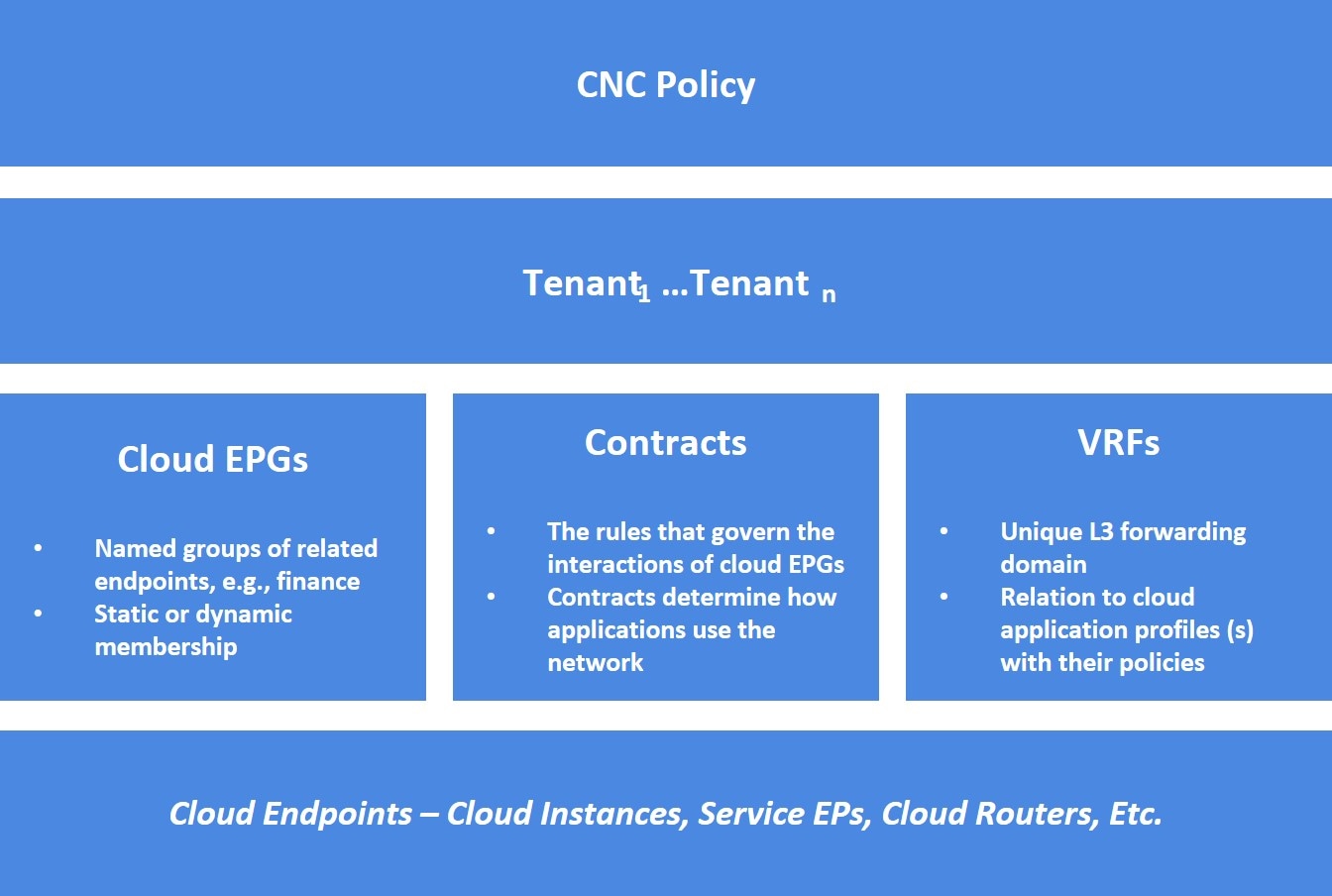
In Cisco APIC, a pre-defined tenant (the tenant common) is available to provide common services to all tenants, such as shared L3Out, private networks, DNS, DHCP, and Active directory. Prior to release 26.0(3), endpoints on an on-premises ACI tenant and endpoints in a user tenant using networking resources from the on-premises tenant common cannot communicate with endpoints on the cloud user tenant. Beginning with release 26.0(3), support is now available for inter-tenant shared services between the on-premises tenant common and cloud user tenants.

Cisco Cloud Network Controller, used in conjunction with Nexus Dashboard Orchestrator, supports inter-tenant shared services in a hybrid cloud environment, allowing you to deploy resources in on-premises tenants and cloud tenants, where contracts are deployed in tenant common. The tenant common still exists on the Cloud Network Controller; however, it is not associated with any cloud account. It is just used for storing filters and contracts that later can be used for a shared service policy. Beginning with release 26.0(3), support is available for having resources in the on-premises Cisco APIC tenant common for both Application EPGs and external EPGs, as well as having inter-tenant shared services in a hybrid cloud environment.

For example, assume that you already have an on-premises Cisco APIC tenant common deployed with a VRF. You can have bridge domain or EPG in the tenant common as you normally would, or you can now create a new user tenant to leverage the VRF and bridge domain in the tenant common.

Prior to release 26.0(3), the following variants of standard tenant are supported:

  • Regular EPG in a user tenant to a cloud tenant

  • External EPG in a user tenant to a cloud tenant

With this update in release 26.0(3), the following variants of the on-premises ACI tenant common are also supported:

  • Regular EPG in the tenant common to a cloud tenant

  • External EPG in the tenant common to a cloud tenant

  • Regular EPG in a user tenant with a bridge domain and VRF in the tenant common to a cloud tenant

  • External EPG in a user tenant with a VRF in the tenant common to a cloud tenant

Use Cases

This section describes several use case examples related to the support for inter-tenant shared services in hybrid cloud environments in release 26.0(3).

On-Premises Cisco APIC Tenant Common Use Case

In this use case, an on-premises Cisco APIC tenant common is deployed with either or both of these configurations:

  • Application EPGs in the bridge domain or subnet

  • External EPG subnet in the L3Out

There is also a contract configured with a user tenant in a cloud site.

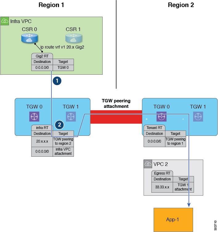
The user tenant in the cloud site can be stretched to all the sites, including the on-premises and other cloud sites, and traffic will still flow between the on-premises tenant common and the user tenant across all sites.

Site1: On-Premises Site

Site2: Cloud Site

VRF in tenant common in Site1: VRF1

VRF in tenant in Site2: VRF2

EPG in Site1: EPG1

EPG in Site2: EPG2

Tenant in Site2 stretched to Site1

Tenant common in Site1 available in Site2

External EPG available in VRF1 in tenant common

External EPG can be created on Site1

Site User Tenants Use Case

In this use case, a tenant (Tenant1) is deployed only in Site1, which is either an on-premises site or a cloud site, and another tenant (Tenant2) is deployed only in Site2, which is a cloud site, and a contract is shared across tenants.

Site1: On-Premises or Cloud Site

Site2: Cloud Site

VRF in tenant (Tenant1) in Site1: VRF1

VRF in tenant (Tenant2) in Site2: VRF2

EPG in Site1: EPG1

EPG in Site2: EPG2

Tenant2 in Site2 stretched to Site1

Tenant1 in Site1 stretched to Site2

External EPG available in VRF1 in Tenant1

External EPG can be created on Site1

Example Configuration Process

The following general steps provide an example for configuring inter-tenant shared services in hybrid cloud environments. See the Nexus Dashboard Orchestrator documentation for more details.

  1. Define the tenants, if necessary.

    In this example scenario, two tenants need to be defined:

    • Cloud only tenant that is associated with a cloud account

    • On-premises common tenant, which is already defined through APIC and exists in both the on-premises ACI and the cloud by default

  2. Define the tenant templates in Nexus Dashboard Orchestrator (NDO) that are associated with the two tenants.

    In this example scenario, you will define two tenant templates in NDO:

    • cloud-tenant-template: Tenant template that is associated with the cloud only tenant

    • common-tenant-template: Tenant template that is associated with the on-premises common tenant

  3. Create a schema (for example, common-schema) with the necessary templates.

    You can have multiple templates within a schema. For example, you could create two templates within this schema:

    • common-policy: In this example scenario, we will make the following configurations in this template:

      • We will associate this template with the common tenant in the cloud site. This template is to deploy the contracts and filter to the common tenant on the cloud (though the common tenant is not associated with any cloud account) and the common tenant on the on-premises ACI site.

      • We will also create two contracts in this template:

        • One for the external EPG from the on-premises site to the cloud site

        • One for a regular EPG from the on-premises site to the cloud site

      • We will also configure the necessary policy contract and filters within this template.

    • common-app: In this example scenario, we will associate this template only with the tenant common in the on-premises site, and we will make the necessary configurations with this on-premises site, such as configurations related to an application profile, VRF, bridge domain, L3Out, external EPG, and so on.

  4. Create a second schema (for example, cloud-schema) with a single template (cloud-only), where we will associate this template only with the cloud only tenant, and we will make the necessary configurations with this cloud site, such as configuruations related to an application profile, VNet/vPC, and so on.

  5. Configure contracts using the contracts that you defined when you created the schemas.

  6. Deploy the configurations in NDO.

Cloud Context Profile

The cloud context profile contains information on the following Cisco Cloud Network Controller components:

  • Availability zones and regions

  • CIDRs

  • CCRs

  • Endpoints

  • EPGs

  • Virtual Networks

  • VRFs

The following sections provide additional information on some of the components that are part of the cloud context profile.

CCR

The CCR is a virtual router that delivers comprehensive WAN gateway and network services into virtual and cloud environments. The CCR enables enterprises to extend their WANs into provider-hosted clouds. Two CCRs are required for Cisco Cloud Network Controller solution.

The Cisco Catalyst 8000V is used with the Cisco Cloud Network Controller. For more information on this type of CCR, see the Cisco Catalyst 8000V Edge software documentation.

About the Cisco Catalyst 8000V

Following are the updates for the Cisco Catalyst 8000V.


Note


Cisco Catalyst 8000V needs to be upgraded to version 17.12.02 using existing upgrade procedure when Cisco Cloud Network Controller gets upgraded. View Triggering an Upgrade of the C8kVs to upgrade Cisco Catalyst 8000V.


Beginning with 26.0(3) release, all Cisco Catalyst 8000V VM instances use metadata version V2.

For more details about how to configure a new VM instance with metadata V2 or migrating an existing VM instance to metadata version V2, see Configuring Metdata Options.

When you upgrade from previous versions of Cisco Cloud Network Controller to 26.0(3), Cisco Catalyst 8000V needs to be upgraded to version 17.12.02, which would have metadata version V2 enabled by default.

Licensing Models

The Cisco Catalyst 8000V on Cisco Cloud Network Controller supports two licensing models:

  1. Bring Your Own License (BYOL)

  2. Pay As You Go (PAYG)

BYOL Licensing Model

The BYOL licensing model on Cisco Catalyst 8000V which requires you to purchase your Catalyst 8000V Cisco DNA license from Cisco and deploy it in the cloud.

Cisco Cloud Network Controller makes use of the “Cisco DNA Advantage” subscription. For features supported by the “Cisco DNA Advantage” subscription, see the Cisco DNA Software SD-WAN and Routing Matrices.

PAYG Licensing Model

Beginning with the 25.0(4) release, the Cisco Cloud Network Controller supports Pay-As-You-Go (PAYG) licensing model on the Cisco Catalyst 8000V which allows users to deploy a Catalyst 8000V instance in the cloud based on the VM size and purchase the usage on an hourly basis.

As you completely depend on the VM size to get the throughput, the PAYG licensing model can be enabled only by first un-deploying the current Cisco Catalyst 8000V and then re-deploying it using the First Time Set Up with the new VM size. For more information, see "Configuring Cisco Cloud Network Controller Using the Setup Wizard" in the Cisco Cloud Network Controller for AWS Installation Guide


Note


The procedure for switching between licenses can also be used if you would like to switch between the two licensing types available.


Note


There are two PAYG options for consuming licenses in the AWS marketplace: Catalyst 8000V Cisco DNA Essentials and Catalyst 8000V Cisco DNA Advantage. Cisco Cloud Network Controller will make use of Catalyst 8000V Cisco DNA Advantage. For features supported by the “Cisco DNA Advantage” subscription, see Cisco DNA Software SD-WAN and Routing Matrices


Throughput Options Based on Licensing Models

The Cisco Catalyst 8000V on Cisco Cloud Network Controller supports two licensing models:

  1. Bring Your Own License (BYOL)

  2. Pay As You Go (PAYG)

1. Bring Your Own License (BYOL)

For this model, the Cisco Catalyst 8000V supports tier-based (T0/T1/T2/T3) throughput options. The following table lists what AWS EC2 instance is used for different router throughput settings for the Cisco Catalyst 8000V:

CCR Throughput

AWS EC2 Instance

T0 (up to 15M throughput)

c5.xlarge

T1 (up to 100M throughput)

c5.xlarge

T2 (up to 1G throughput)

c5.xlarge

T3 (up to 10G throughput)

c5.9xlarge

Tier2 (T2) is the default throughput supported by Cisco Cloud Network Controller.

2. Pay-As-You-Go Licensing Model

For this model, Cisco Cloud Network Controller supports a range of AWS EC2 instances for cloud networking needs powered by Cisco’s Catalyst 8000V virtual router.

The table below shows the cloud instance type supported by Cisco Cloud Network Controller on AWS.-

AWS EC2 Instance

CCR Throughput

vCPUs

Memory

c5.xlarge

up to 5 Gigabit throughput

4

8 GiB

c5.2xlarge

up to 10 Gigabit throughput

8

16 GiB

c5.4xlarge

up to 10 Gigabit throughput

16

32 GiB

c5.9xlarge

up to 10 Gigabit throughput

36

72 GiB

c5n.xlarge

up to 25 Gigabit throughput

4

10.5 GiB

c5n.2xlarge

up to 25Gigabit throughput

8

21 GiB

c5n.4xlarge

up to 25 Gigabit throughput

16

42 GiB

c5n.9xlarge

up to 50 Gigabit throughput

36

96 GiB

Private IP Address Support for Cisco Cloud Network Controller and CCR in AWS

By default, CCR interfaces are assigned private IP addresses only and assignment of public IP addresses to CCR interfaces is optional. Private IP addresses are always assigned to all the interfaces of a CCR. The private IP address of GigabitEthernet1 of a CCR is used as BGP and OSPF router IDs.

To enable CCR private IP addresses for inter-site connectivity, where you are disabling public IP addresses for the CCR interfaces, see the Managing Regions (Configuring a Cloud Template) Using the Cisco Cloud Network Controller GUI procedure.

By default, a private IP address is assigned to the management interface of the Cisco Cloud Network Controller and assigning a public IP address is optional. To disable public IP to the Cisco Cloud Network Controller so that a private IP address is used for connectivity, see the Deploying the Cisco Cloud Network Controller in AWS procedure in the Cisco Cloud Network Controller for AWS Installation Guide.

Restrictions for CCR with Private IP Address

When public IP is disabled, the underlay inter-site connectivity cannot be Public internet because Public Internet requires a public IP address. The underlay inter-site connectivity can only be one of the following:

  • Private connection for connecting to an on-premise ACI site, which is through AWS Direct Connect or Azure Express Route

  • Cloud backbone for connecting to a Cisco Cloud Network Controller site of the same cloud provider, which is through AWS VPC Peering or Azure Vnet Peering

Communicating to External Sites From Regions Without a CCR

Support is available for communication with an external site from regions without a CCR. This is accomplished by making use of the AWS Transit Gateway feature. When you enable the AWS Transit Gateway feature on Cisco Cloud Network Controller, you also enable peering between all managed regions on AWS. In this way, the AWS Transit Gateway peering feature allows the Cisco Cloud Network Controller to address the issue of communicating with external sites from regions without a CCR. It addresses this issue by having traffic rerouted to a region with a CCR.

Using the AWS Transit Gateway feature, when traffic from a region without a CCR tries to egress out of a site, this traffic will be routed to the infra VPC for the closest region with a CCR. After the traffic is rerouted to that region's infra VPC, that CCR is used to egress out the packet. For ingress traffic, packets coming from an external site can reach any region's CCR and then be routed to the destination region using the AWS Transit Gateway peering in the ingress data path.

In these situations, traffic is rerouted automatically when the system recognizes that external traffic is egressing or ingressing through a region without a CCR. However, you must have the following components configured in order for the system to automatically perform this rerouting task:

  • AWS Transit Gateway must be configured. If AWS Transit Gateway is not already configured, see Increasing Bandwidth Between VPCs by Using AWS Transit Gateway for those instructions.

  • CCRs must be deployed in at least one region. Even though this enhancement allows you to communicate with an external site from a region that does not contain a CCR, in order to do this, you must have another separate region that does contain a CCR so that traffic can be rerouted from the region without a CCR to the region with a CCR.

The following figure shows an example scenario where traffic is rerouted automatically when the system recognizes that external traffic is egressing from a region without a CCR.

The following occurs when the Cisco Cloud Network Controller recognizes that Region 2 does not have a CCR, but traffic is egressing out to an external site (shown with the green arrow and circles):

  1. Traffic flow begins egressing out from the CIDR in App-1 in Region 2 to a remote site. Note that the endpoint is configured with the appropriate outbound rule to allow the remote site CIDR.

  2. The VPC 2 egress route table has the remote site CIDR, which then has the AWS Transit Gateway as the next hop. The AWS Transit Gateway information is programmed automatically based on the configured contracts.

  3. A 0.0.0.0/0 route is inserted in the AWS Transit Gateway route table, which essentially tells the system to take the AWS Transit Gateway peering attachment if traffic is egressing out to an external site but there is no CCR in this region. In this situation, the AWS Transit Gateway peering attachment goes to another region that does have a CCR (Region 1 in the example scenario). The region with a CCR that will be used is chosen based on geographical proximity to the region that does not have a CCR.

  4. The packet is first forwarded to the infra VPC in the region with the CCR (Region 1), and is then forwarded to the gigabit ethernet network interface on the CCR that is associated with the appropriate VRF group.

  5. The gigabit 2 inbound security group on the CCR in Region 1 is configured to allow traffic from the remote region VPC.

It's useful to note that in the egress example shown above:

  • For steps 1 and 2, there is no change from pre-release 5.2(1) behavior.

  • Step 3 is behavior that is new and unique to this feature in release 5.2(1), where the redirect occurs to the TGW peering attachment from the region without a CCR to the region with a CCR. In addition, step 3 occurs on the AWS cloud.

  • Steps 4 and 5 would normally occur in Region 2 before release 5.2(1), but only if Region 2 had a CCR. However, because Region 2 does not have a CCR, with this feature in release 5.2(1), these steps are taking place in Region 1 where a CCR is present.

The following figure shows an example scenario where traffic is rerouted automatically when the system recognizes that external traffic is ingressing to a region without a CCR.

The following occurs when the Cisco Cloud Network Controller recognizes that Region 2 does not have a CCR, but traffic is ingressing in from an external site to a CIDR in App-1 in Region 2 (shown with the blue arrow and circles):

  1. Normally, the CCR in Region 1 would only advertise the CIDRs that are local to that region. However, with this enhancement that is part of release 5.2(1), all CCRs in all regions now advertise CIDRs from all remote regions. Therefore, in this example, the CCR in Region 1 will also advertise the CIDRs that are in Region 2 (assuming AWS Transit Gateway peering is configured between both regions and the contracts are configured correctly). In this situation, the traffic ingresses in from an external site to the CCR in Region 1, where the CCR in Region 1 advertises the static route for the remote region VPC CIDRs.

  2. The infra route table (the AWS Transit Gateway route table in Region 1) has the next hop to the AWS Transit Gateway peering attachment to Region 2.

It's useful to note that in the ingress example shown above:

  • Both steps (steps 1 and 2) in the ingress example shown above are new and unique to this feature in release 5.2(1).

  • Step 1 in the ingress example shows configurations programmed on the CCR.

  • Step 2 in the ingress example occurs on the AWS cloud.

Support for ECMP Forwarding from Remote Sites for CCRs

Support is available for ECMP with CCRs, where traffic from CCRs will be forwarded to all ECMP paths received from a destination site. This support is automatically enabled and requires no manual configuration to enable.

Preference For Routes to CCRs in Regions with Local CIDRs

Every CIDR that is configured is local to a specific region. With multiple regions in a cloud, CCRs from all regions advertise the CIDRs for redundancy. However, rather than have CCRs from all regions advertise the CIDRs with the same preference, support is available for having CCRs advertise with a higher preference from the region where the CIDR is local. This causes the on-premises site or the remote cloud site to direct traffic directly to the region where the CIDR is local. If the CCRs in the local region fail, the paths from the other regions can be used for data forwarding.

Availability Zones

Two types of availability zones are supported for Cisco Cloud Network Controller:

  • Virtual availability zones: Cisco Cloud Network Controller supports only two virtual availability zones per region in AWS, where Cisco Cloud Network Controller creates two virtual availability zones for each region using the format <region-name>a and <region-name>b. For example, under the us-west-1 region, Cisco Cloud Network Controller creates the two virtual availability zones us-west-1a and us-west-1b.

    To view the virtual availability zones for your Cisco Cloud Network Controller, navigate to Cloud Resources > Availability Zones, then click the Virtual Availability Zones tab.

  • Cloud availability zones: This type of availability zone allows for multiple availability zones in each AWS region with Cisco Cloud Network Controller.

    To view the cloud availability zones for your Cisco Cloud Network Controller, navigate to Cloud Resources > Availability Zones, then click the Cloud Availability Zones tab.

Migrating from Virtual Availability Zones to Cloud Availability Zones

If you have deployments where you have virtual availability zones configured, we recommend that you migrate from the virtual availability zones to the cloud availability zones.

  • You can migrate individual subnets or all of the subnets in a CIDR block range as part of the availability zone migration.

  • Migrating from older virtual availability zones to the newer cloud availability zones will not cause have any functional impact, such as a traffic drop, in the cloud resources in AWS.


Note


The following steps describe how to migrate from virtual availability zones to cloud availability zones through the cloud context profile, but you can also migrate availability zones by clicking the Intent icon ( ) and selecting Availability Zone Configuration Migration.


To migrate from virtual availability zones to cloud availability zones:

  1. Navigate to the cloud context profile that was configured previously with the older virtual availability zones.

    In the left nav pane, navigate to Application Management > Cloud Context Profiles, then locate the cloud context profile that was configured previously with the older virtual availability zones.

  2. Double-click on that cloud context profile.

    The details panel for that cloud context profile appears with the Overview tab selected automatically.

    View the entries in the Availability Zone column in the Overview tab to determine if you have virtual availability zones in this cloud context profile that you can migrate to cloud availability zones.

  3. Click Actions > Migrate Subnet Configuration.

    The Availability Zone Configuration Migration window appears.

  4. Select the subnets associated with the virtual availability zones that you want to migrate to cloud availability zones.

    • All of the subnets listed in this window that are associated with virtual availability zones will be selected by default. Manually deselect any subnets associated with virtual availability zones that you do not want to migrate to cloud availability zones.

    • For each virtual availability zone that will be migrated over to cloud availability zones, make a note of the entry in the Cloud Availability Zones column to determine the new availability zone value for that subnet, if necessary.

  5. Click Migrate Subnet Configuration.

    The selected virtual availability zones are migrated to cloud availability zones.

Guidelines and Limitations

Following are the guidelines and limitations for support of multiple availability zones:

  • Support for cloud availability zones, where you can have more than two availability zones, is available for user tenants only. Infra tenants will continue to use virtual availability zones which have a limit of two availability zones.

VRFs

A Virtual Routing and Forwarding (VRF) object (fvCtx) or context is a tenant network (called a private network in the Cisco Cloud Network Controller GUI. A tenant can have multiple VRFs. A VRF is a unique Layer 3 forwarding and application policy domain. The following figure shows the location of VRFs in the management information tree (MIT) and their relation to other objects in the tenant.

Figure 4. VRFs

A VRF defines a Layer 3 address domain. One or more cloud context profiles are associated with a VRF. You can only associate one cloud context profile with a VRF in a given region. All the endpoints within the Layer 3 domain must have unique IP addresses because it is possible to forward packets directly between these devices if the policy allows it. A tenant can contain multiple VRFs. After an administrator creates a logical device, the administrator can create a VRF for the logical device, which provides a selection criteria policy for a device cluster. A logical device can be selected based on a contract name, a graph name, or the function node name inside the graph.

Support for VRF to span across multiple VPCs within a Region

Prior to 26.0(2), multiple VPCs belonging to the same VRF would need to be deployed in different regions. Beginning with 26.0(2), Cisco Cloud Network Controller will have the ability to configure multiple VPCs in a VRF inside one region. This helps enable automatic route propogation across all the VPCs grouped under one VRF.

The advantages are as follows :

  • This is necessary in situations where a customer may want multiple VPCs configured in the same VRF.

  • This is also beneficial in cases if the customer wants multiple VPCs in the same region. Prior to this feature, the customer would have to deploy the VPCs in different VRFs and setup contracts and leak routes to allow communication of the VPCs with each other. This feature helps simplify the configuration.


Note


VPCs with overlapping subnets cannot be associated with a single VRF in a region. This applies to brownfield VPCs as well.

Downgrade is supported. However, if there are multiple cloud context profiles under the same VRF, they need to be removed. You can keep only one cloud context profile under the same VRF in that region.


Cloud Application Profiles

A cloud application profile (cloudAp) defines the policies, services and relationships between cloud EPGs. The following figure shows the location of cloud application profiles in the management information tree (MIT) and their relation to other objects in the tenant.
Figure 5. Cloud Application Profiles

Cloud application profiles contain one or more cloud EPGs. Modern applications contain multiple components. For example, an e-commerce application could require a web server, a database server, data located in a storage service, and access to outside resources that enable financial transactions. The cloud application profile contains as many (or as few) cloud EPGs as necessary that are logically related to providing the capabilities of an application.

Cloud EPGs can be organized according to one of the following:

  • The application they provide, such as a DNS server or SAP application (see Tenant Policy Example in Cisco APIC REST API Configuration Guide).

  • The function they provide (such as infrastructure)

  • Where they are in the structure of the data center (such as DMZ)

  • Whatever organizing principle that a cloud infrastructure or tenant administrator chooses to use

Cloud Endpoint Groups

The cloud endpoint group (cloud EPG) is the most important object in the policy model. The following figure shows where application cloud EPGs are located in the management information tree (MIT) and their relation to other objects in the tenant.
Figure 6. Cloud Endpoint Groups

A cloud EPG is a managed object that is a named logical entity that contains a collection of endpoints. Endpoints are devices that are connected to the network directly or indirectly. They have an address (identity), a location, attributes (such as version or patch level), and are virtual. Knowing the address of an endpoint also enables access to all its other identity details. Cloud EPGs are fully decoupled from the physical and logical topology. Endpoint examples include servers, virtual machines, storage services, or clients on the Internet. Endpoint membership in a cloud EPG can be dynamic or static.

The CCNC cloud infrastructure can contain the following types of cloud EPGs:

  • Cloud endpoint group (cloudEPg)

  • Cloud external endpoint group (cloudExtEPg)

Cloud EPGs contain endpoints that have common policy requirements such as security or Layer 4 to Layer 7 services. Rather than configure and manage endpoints individually, they are placed in a cloud EPG and are managed as a group.

Policies apply to cloud EPGs, never to individual endpoints.

Regardless of how a cloud EPG is configured, cloud EPG policies are applied to the endpoints they contain.

WAN router connectivity to the cloud infrastructure is an example of a configuration that uses a static cloud EPG. To configure WAN router connectivity to the cloud infrastructure, an administrator configures a cloudExtEPg cloud EPG that includes any endpoints within an associated WAN subnet. The cloud infrastructure learns of the cloud EPG endpoints through a discovery process as the endpoints progress through their connectivity life cycle. Upon learning of the endpoint, the cloud infrastructure applies the cloudExtEPg cloud EPG policies accordingly. For example, when a WAN connected client initiates a TCP session with a server within an application (cloudEPg) cloud EPG, the cloudExtEPg cloud EPG applies its policies to that client endpoint before the communication with the (cloudExtEPg) cloud EPG web server begins. When the client server TCP session ends, and communication between the client and server terminates, the WAN endpoint no longer exists in the cloud infrastructure.

The Cisco Cloud Network Controller uses endpoint selectors to assign endpoints to Cloud EPGs. The endpoint selector is essentially a set of rules that are run against the cloud instances that are assigned to the AWS VPC managed by CCNC. Any endpoint selector rules that match endpoint instances assign that endpoint to the Cloud EPG. The endpoint selector is similar to the attribute-based microsegmentation available in Cisco ACI.

Contracts

In addition to cloud EPGs, contracts (vzBrCP) are key objects in the policy model. Cloud EPGs can only communicate with other cloud EPGs according to contract rules. The following figure shows the location of contracts in the management information tree (MIT) and their relation to other objects in the tenant.

Figure 7. Contracts

An administrator uses a contract to select one or more types of traffic that can pass between cloud EPGs, including the protocols and ports allowed. If there is no contract, inter-EPG communication is disabled by default. There is no contract required for intra-EPG communication; intra-EPG communication is always implicitly allowed.

Contracts govern the following types of cloud EPG communications:

  • Between cloud EPGs (cloudEPg), both intra-tenant and inter-tenant


    Note


    In the case of a shared service mode, a contract is required for inter-tenant communication. A contract is used to specify static routes across VRFs, although the tenant VRF does not enforce a policy.
  • Between cloud EPGs and cloud external EPGs (cloudExtEPg)

Contracts govern the communication between cloud EPGs that are labeled providers, consumers, or both. The relationship between a cloud EPG and a contract can be either a provider or consumer. When a cloud EPG provides a contract, communication with that cloud EPG can be initiated from other cloud EPGs as long as the communication complies with the provided contract. When a cloud EPG consumes a contract, the cloud endpoints in the consuming cloud EPG may initiate communication with any cloud endpoint in a cloud EPG that is providing that contract.


Note


A cloud EPG can both provide and consume the same contract. A cloud EPG can also provide and consume multiple contracts simultaneously.

Filters and Subjects Govern Cloud EPG Communications

Subject and filter managed-objects enable mixing and matching among cloud EPGs and contracts so as to satisfy various applications or service delivery requirements. The following figure shows the location of application subjects and filters in the management information tree (MIT) and their relation to other objects in the tenant.
Figure 8. Subjects and Filters

Contracts can contain multiple communication rules and multiple cloud EPGs can both consume and provide multiple contracts. A policy designer can compactly represent complex communication policies and re-use these policies across multiple instances of an application.


Note


Subjects are hidden in Cisco Cloud Network Controller and not configurable. For rules installed in AWS, source port provided in the filter entry s not taken into account.


Subjects and filters define cloud EPG communications according to the following options:

  • Filters are Layer 2 to Layer 4 fields, TCP/IP header fields such as Layer 3 protocol type, Layer 4 ports, and so forth. According to its related contract, a cloud EPG provider dictates the protocols and ports in both the in and out directions. Contract subjects contain associations to the filters (and their directions) that are applied between cloud EPGs that produce and consume the contract.


    Note


    When a contract filter match type is All, best practice is to use the VRF unenforced mode. Under certain circumstances, failure to follow these guidelines results in the contract not allowing traffic among cloud EPGs in the VRF.
  • Subjects are contained in contracts. One or more subjects within a contract use filters to specify the type of traffic that can be communicated and how it occurs. For example, for HTTPS messages, the subject specifies the direction and the filters that specify the IP address type (for example, IPv4), the HTTP protocol, and the ports allowed. Subjects determine if filters are unidirectional or bidirectional. A unidirectional filter is used in one direction. Unidirectional filters define in or out communications but not the same for both. Bidirectional filters are the same for both; they define both in and out communications.


    Note


    For rules that are installed in AWS, the source port provided in the filter entry is not taken into account.


  • CCNC contracts rendered in AWS constructs are always stateful, allowing return traffic.

About the Cloud Template

The cloud template provides a template that configures and manages the Cisco Cloud Network Controller infra network. The template requires only the most essential elements for the configuration. From these elements, the cloud template generates a detailed configuration necessary for setting up the Cisco Cloud Network Controller infra network. However, it is not a one-time configuration generation—it is possible to add, modify, or remove elements of the template input. The cloud template updates the resulting configuration accordingly.

One of the central things in the AWS network configuration is the Virtual Private Cloud (VPC). AWS supports many regions worldwide and one VPC is specific to one region.

The cloud template accepts one or more region names and generates the entire configuration for the infra VPCs in those regions. They are the infra VPCs. The Cisco Cloud Network Controller-managed object (MO) corresponding to the AWS VPC is cloudCtxProfile. For every region specified in the cloud template, it generates the cloudCtxProfile configuration. A cloudCtxProfile is the topmost MO for all the configuration corresponding to a region. Underneath, it has many of other MOs organized as a tree to capture a specific configuration. A cloudCtxProfile MO generated by the cloud template carries ctxProfileOwner == SYSTEM. For the non-infra network, it is possible to configure cloudCtxProfile directly; in this case, cloudCtxProfile carries ctxProfileOwner == USER.

A primary property of an AWS VPC is the CIDR. Every region needs a unique CIDR. In Cisco Cloud Network Controller, you can provide the CIDRs for the infra VPCs. The CIDRs for the first two regions come from the Cloud Formation Template (CFT) that deploys the Cisco Cloud Network Controller AMI on the AWS. The cloudApicSubnetPool MO provides CIDRs for the additional regions directly to the Cisco Cloud Network Controller. In the Cisco Cloud Network Controller configuration, the cloudCidr MO, which is a child of cloudCtxProfile, models the CIDR.

The cloud template generates and manages a huge number of MOs in the cloudCtxProfile subtree including, but not limited to, the following:

  • Subnets

  • Association of subnets to AWS availability zones

  • Cloud routers

  • IP address allocation for the cloud router interfaces

  • IP address allocation and configuration for tunnels

  • IP address allocation and configuration for loopbacks

Without the cloud template, you would be responsible for configuring and managing these.

The Cisco Cloud Template MO table contains a brief summary of the inputs (MOs) to the cloud template.

Table 1. Cloud Template MOs

MO

Purpose

cloudtemplateInfraNetwork

The root of the cloud template configuration. Attributes include:

numRoutersPerRegion—The number of cloud routers for each cloudRegionName specified under cloudtemplateIntNetwork.

cloudtemplateProfile

Configuration profile for all the cloud routers. Attributes include:

  • routerUsername

  • routerPassword

  • routerThroughput

  • routerLicenseToken

  • routeDataInterfacePublicIP

  • routerMgmtInterfacePublicIP

cloudtemplateIntNetwork

Contains a list of regions, which specify where you deploy the cloud routers. Each region is captured through a cloudRegionName child MO

cloudtemplateExtNetwork

Contains infra network configuration input that is external of the cloud.

Contains a list of regions where cloud routers are configured for external networking.

Each region is captured through a cloudRegionName child MO

cloudtemplateVpnNetwork

Contains information for setting up a VPN with an ACI on-premises site or another Cisco Cloud Network Controller site.

cloudtemplateIpSecTunnel

Captures the IP address of the IPSec peer in the ACI on-premises site.

cloudtemplateOspf

Captures the OSPF area to be used for the VPN connections.

cloudtemplateBgpEvpn

Captures the peer IP address, ASN, and so forth, for setting up the BGP session with the on-premises site.

In Cisco Cloud Network Controller, the layering of MOs is slightly different from a regular Cisco APIC due to the cloud template. In a regular Cisco APIC, you post logical MOs that go through two layers of translation:

  1. Logical MO to resolved MO

  2. Resolved MO to concrete MO

In Cisco Cloud Network Controller, there is an additional layer of translation for the infra network. This additional layer is where the cloud template translates logical MOs in the cloudtemplate namespace to logical MOs in the cloud namespace. For configurations outside of the infra network, you post logical MOs in the cloud namespace. In this case, the MOs go through the usual two-layer translation as in the regular Cisco APIC.

Figure 9. Cloud and Cloud Template MO Conversion

Note


For information about configuring the cloud template, see Configuring Cisco Cloud Network Controller Components

Managed Object Relations and Policy Resolution

Relationship-managed objects express the relation between managed object instances that do not share containment (parent-child) relations. MO relations are established between the source MO and a target MO in one of the following two ways:

  • An explicit relation, such as with cloudRsZoneAttach and cloudRsCloudEPgCtx, defines a relationship that is based on the target MO distinguished name (DN).

  • A named relation defines a relationship that is based on the target MO name.

The dotted lines in the following figure show several common MO relations.
Figure 10. MO Relations

For example, the dotted line between the cloud EPG and the VRF defines the relation between those two MOs. In this figure, the cloud EPG (cloudEPg) contains a relationship MO (cloudRsCloudEPgCtx) that is named with the name of the target VRF MO (fvCtx). For example, if production is the VRF name (fvCtx.name=production), then the relation name is production (cloudRsCloudEPgCtx.tnFvCtxName=production).

In the case of policy resolution based on named relations, if a target MO with a matching name is not found in the current tenant, the CCNC cloud infrastructure tries to resolve in the common tenant. For example, if the user tenant cloud EPG contained a relationship MO targeted to a VRF that did not exist in the tenant, the system tries to resolve the relationship in the common tenant. If a named relation cannot be resolved in either the current tenant or the common tenant, the CCNC cloud infrastructure attempts to resolve to a default policy. If a default policy exists in the current tenant, it is used. If it does not exist, the CCNC cloud infrastructure looks for a default policy in the common tenant. Cloud context profile, VRF, and contract (security policy) named relations do not resolve to a default.

Default Policies


Warning


Default policies can be modified or deleted. Deleting a default policy can result in a policy resolution process to complete abnormally.


The CCNC cloud infrastructure includes default policies for many of its core functions. Examples of default policies include the following:

  • Cloud AWS provider (for the infra tenant)

  • Monitoring and statistics


Note


To avoid confusion when implementing configurations that use default policies, document changes made to default policies. Be sure that there are no current or future configurations that rely on a default policy before deleting a default policy. For example, deleting a default firmware update policy could result in a problematic future firmware update.


A default policy serves multiple purposes:

  • Allows a cloud infrastructure administrator to override the default values in the model.

  • If an administrator does not provide an explicit policy, the Cisco Cloud Network Controller applies the default policy. An administrator can create a default policy and the Cisco Cloud Network Controller uses that unless the administrator provides any explicit policy.

The following scenarios describe common policy resolution behavior:

  • A configuration explicitly refers to the default policy: if a default policy exists in the current tenant, it is used. Otherwise, the default policy in tenant common is used.

  • A configuration refers to a named policy (not default) that does not exist in the current tenant or in tenant common: if the current tenant has a default policy, it is used. Otherwise, the default policy in tenant common is used.


    Note


    The scenario above does not apply to a VRF in a tenant.


  • A configuration does not refer to any policy name: if a default policy exists in the current tenant, it is used. Otherwise, the default policy in tenant common is used.

The policy model specifies that an object is using another policy by having a relation-managed object (MO) under that object and that relation MO refers to the target policy by name. If this relation does not explicitly refer to a policy by name, then the system tries to resolve a policy that is called default. Cloud context profiles and VRFs are exceptions to this rule.

Shared Services

Cloud EPGs in one tenant can communicate with cloud EPGs in another tenant through a contract interface that is contained in a shared tenant. Within the same tenant, a cloud EPG in one VRF can communicate with another cloud EPG in another VRF through a contract defined in the tenant. The contract interface is an MO that can be used as a contract consumption interface by the cloud EPGs that are contained in different tenants. By associating to an interface, a cloud EPG consumes the subjects that are represented by the interface to a contract contained in the shared tenant. Tenants can participate in a single contract, which is defined at some third place. More strict security requirements can be satisfied by defining the tenants, contract, subjects, and filter directions so that tenants remain isolated from one another.

Follow these guidelines when configuring shared services contracts:

  • A shared service is supported only with non-overlapping and non-duplicate CIDR subnets. When configuring CIDR subnets for shared services, follow these guidelines:

    • CIDR subnets leaked from one VRF to another must be disjointed and must not overlap.

    • CIDR subnets advertised from multiple consumer networks into a VRF or vice versa must be disjointed and must not overlap.