New and Changed Information
The following table provides an overview of the significant changes up to this current release. The table does not provide an exhaustive list of all changes or of the new features up to this release.
|
Cisco Cisco Cloud Network Controller Release Version |
Feature |
Description |
|---|---|---|
|
25.1(1) |
Support for importing existing Google Cloud brownfield VPCs into Cisco Cloud Network Controller. |
This release provides support for importing existing Google Cloud brownfield VPCs into Cisco Cloud Network Controller. |
|
25.0(5) |
Beginning with release 25.0(5), the Cisco Cloud APIC is renamed to Cisco Cloud Network Controller. |
Benefits of Importing Existing Google Cloud Brownfield VPCs into Cisco Cloud Network Controller
Prior to release 25.1(1), cloud deployments through Cisco Cloud Network Controller are considered greenfield deployments, where the configurations for the necessary components (resource groups, VPCs, CIDRs, subnets, and so on) are done through the Cisco Cloud Network Controller. You would then deploy the services under these resource groups that are created through the Cisco Cloud Network Controller to bring up your applications.
Many users who have adopted Google Cloud for their data center extensions have hundreds of VPCs and instances that are already deployed in the cloud. This results in having two different environments, one for the new greenfield configurations through Cisco Cloud Network Controller and existing brownfield configurations on Google Cloud. This is not ideal if you don't want separate control points for your existing cloud resources once you adopt the Cisco Cloud Network Controller solution.
Prior to release 25.1(1), existing brownfield environments, where the resource groups and VPCs were created without using Cisco Cloud Network Controller, were not able to coexist in a Cisco Cloud Network Controller-managed site. Beginning with release 25.1(1), support is now available for importing existing brownfield Google Cloud VPCs into Cisco Cloud Network Controller. This enhancement uses VPC peering to provide communication between greenfield VPCs configured through Cisco Cloud Network Controller and brownfield Google Cloud VPCs that were configured outside of Cisco Cloud Network Controller. For more information on VPC peering, see "Inter-Site Connectivity Using BGP-EVPN" in the Cisco Cloud Network Controller for Google Cloud User Guide , Release 25.1(1) or later.
In addition, if you have existing cloud resources under a brownfield Google Cloud VPC that you do not want to import into Cisco Cloud Network Controller (such as CIDRs or subnets), these existing cloud resources will continue to exist in the cloud without any modifications or deletions from Cisco Cloud Network Controller. With a read-only access policy, aside from running a read inventory, Cisco Cloud Network Controller will have no privileges on these existing cloud resources.
Terminology Used In This Document
This section introduces some of the key terminology and concepts that are used in this document:
- Greenfield VPC
- A VPC on Google Cloud that is created by Cisco Cloud Network Controller based on the cloud context profile.
- Brownfield VPC
- A VPC that is created directly in Google Cloud and imported into the Cisco Cloud Network Controller.
- Access policy
- Policies that are created on Cisco Cloud Network Controller that denote the respective privilege. The access policies are:
-
-
Read Only: Cisco Cloud Network Controller does not configure or provision anything in existing brownfield projects with this access policy, and you configure security and routing in existing brownfield projects.
-
Routing Only: Cisco Cloud Network Controller controls routing in existing brownfield projects with this access policy, and you will configure security in existing brownfield projects.

Note
The Routing & Security access policy, which is available in Cisco Cloud Network Controller with AWS or Azure, is not supported in Cisco Cloud Network Controller with Google Cloud.
-
- Greenfield cloud context profile
- A cloud context profile that has no relation to any access policy or has no relation to the Default access policy.
Workflow for Importing Existing Brownfield Cloud VPCs Into Cisco Cloud Network Controller
Following is an example of the import process of a brownfield Google Cloud VPC into Cisco Cloud Network Controller.
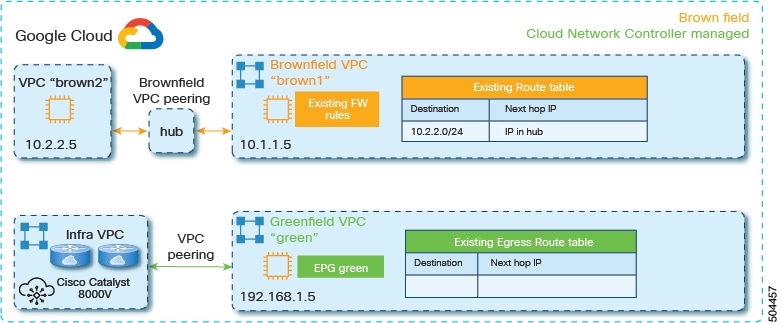
The following graphic shows an example scenario, where there are existing brownfield Google Cloud VPCs (the brown1 VPC, the brown2 VPC, and a hub VPC) that exist outside of the Cisco Cloud Network Controller (were not configured or maintained by Cisco
Cloud Network Controller), along with greenfield Google Cloud VPCs that were configured through Cisco Cloud Network Controller
(the green VPC and the infra VPC for the Cisco Catalyst 8000Vs).
Following is the general workflow for importing existing brownfield cloud VPCs into Cisco Cloud Network Controller:
-
Create a new tenant to be used with the brownfield cloud context profile, if necessary.
If the brownfield VPC is in a different account, then you must create a new tenant.
This new account created under the tenant will also have a relation to a read-only policy, which will not trigger the creation of event collection or stat collection resources on these accounts. Only the inventory pull will be done for these accounts.
For instructions on creating a new tenant, see the following sections in the Cisco Cloud Network Controller for Google Cloud User Guide, Release 25.0(x) or later:
-
"Understanding Google Cloud Deployments with Cisco Cloud Network Controller"
-
"Creating a Tenant"
-
-
Import the existing brownfield VPC, CIDR, and subnet configurations in to Cisco Cloud Network Controller.
You do this by creating a cloud context profile corresponding to the brownfield VPC, which creates an association between the brownfield VPC and a VRF. The cloud context profile in Cisco Cloud Network Controller is an object that is used to link between the brownfield VPC and a VRF. To import the brownfield VPC, you must first create a VRF object, which is a placeholder for the cloud context profile association that will be used later when importing the brownfield VPC.
In this step in the example scenario, you would import the brownfield
brown1VPC and choose a subnet to import.-
If you use the Read Only access policy when you import the brownfield VPC, the VPC peering configuration in the brownfield VPC is not updated by the Cisco Cloud Network Controller. You will configure the VPC peering manually in the next step.
-
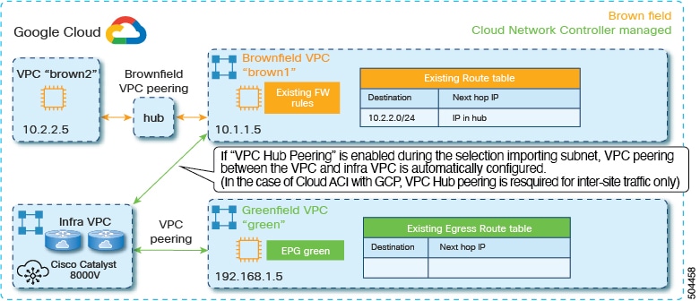
When you select the subnet to import, if you enable the VPC Hub Peering option, then VPC peering between the VPC and the infra VPC is configured automatically. Note that VPC hub peering is required only for inter-site traffic.
See Creating a Brownfield Cloud Context Profile for those procedures.
-
-
Configure VPC peering for the brownfield VPCs.
If you assigned a Read Only access policy for the brownfield VPC, the Cisco Cloud Network Controller does not program the VPC peering from the brownfield VPC to the infra VPCs. You must program the VPC peering from the brownfield VPC to the infra VPCs.
See Adding Peering from Brownfield VPC to Infra VPCs in Google Cloud for those procedures.
-
Determine if you are enabling the contract-based routing option or not for this brownfield VPC import.
-
If you are not enabling the contract-based routing option for this brownfield VPC import, then you would next configure inter-VRF route leaking between the brownfield VPC (the
brown1VPC in the example scenario) and the greenfield VPC (thegreenVPC in the example scenario). See Configuring Inter-VRF Route Leaking for those procedures.When you add the contract between the
greenEPG and thebrown1EPG, VPC peering is enabled automatically between thegreenVPC and thebrown1VPC. In addition, the routes in the route table in one VPC is learned automatically in the other VPC when VPC peering is enabled between the two VPCs.After you configured inter-VRF route leaking between the brownfield and the greenfield VPCs, you would then create an EPG to be associated with the brownfield cloud context profile, as described in the next step.
-
If you are enabling the contract-based routing option for this brownfield VPC import, then you would not have to configure inter-VRF route leaking. You would create an EPG to be associated with the brownfield cloud context profile next instead, as described in the next step.
Note
Because Cisco Cloud Network Controller with Google Cloud does not support the Routing & Security access policy, the firewall rules in the brownfield VPC are not updated by the Cisco Cloud Network Controller.
-
-
Create an EPG associated with the brownfield cloud context profile.
In this step in the example scenario, you would create an EPG (
brown1EPG in this example scenario) and you will add a contract between thegreenEPG (consumer) and thebrown1EPG (provider).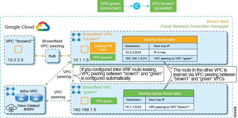
See Creating an EPG Associated With the Brownfield Cloud Context Profile for those procedures.
Guidelines and Restrictions
Following are the guidelines and restrictions when importing existing brownfield Google Cloud configurations into Cisco Cloud Network Controller.
-
The Routing & Security access policy is not supported when importing existing brownfield Google Cloud configurations into Cisco Cloud Network Controller.
-
Access policy configurations for Google Cloud are supported only at the VPC level (unlike other cloud providers, where access policy configurations are also supported at the global level).
-
For Google Cloud, you must have greenfield-specific VRFs and brownfield-specific VRFs. You cannot have a single VRF that is used with both greenfield and brownfield cloud context profiles.
-
Only subnet-based endpoint selectors are supported for the brownfield EPGs in release 25.1(1).
-
All cloud context profiles under a single VPC will have the same access policy. In other words, if you have two cloud context policies under a VPC that are both set with a Read Only access policy, and then you change the access policy to Routing Only for one of the cloud context profiles, the access policy for the other cloud context profile under that VPC will automatically change to Routing Only, too.
Creating a Brownfield Cloud Context Profile
The following topics provide information for creating a brownfield cloud context profile.
About Brownfield Cloud Context Profiles
A brownfield cloud context profile refers to a configuration that is posted on the Cisco Cloud Network Controller that is associated with the brownfield VPC.
-
You can define brownfield cloud context profiles under any tenant, regardless of whether it is associated with a greenfield (Cisco Cloud Network Controller-managed) account or if it is associated with a brownfield account.
-
If you have a greenfield account where you already have Cisco Cloud Network Controller-configured VPCs, and you also have brownfield VPCs in the same account, you can define the brownfield cloud context profile under the tenant associated with the greenfield account. In other words, if you already have a tenant created that is being used with a greenfield cloud context profile, that same tenant can be used for the brownfield cloud context profile (the unmanged VPC import) creation as well.
Following are the necessary parameters that you will have to configure for a brownfield cloud context profile:
-
VRF: The VRF on the Cisco Cloud Network Controller where you want to associate the brownfield VPC
-
Region: The region where the brownfield VPC is present on the cloud
-
VPC ID: The cloud provider ID of this brownfield VPC on the cloud
-
CIDRs: The CIDRs that need to be referred to on the Cisco Cloud Network Controller
The Cisco Cloud Network Controller will use these parameters to map the brownfield cloud context profile to the given VPC on the cloud.
Creating a Brownfield Cloud Context Profile Using the GUI
Before you begin
Review the information provided in About Brownfield Cloud Context Profiles before going through these procedures.
Procedure
| Step 1 |
Create a new tenant to be used with the brownfield cloud context profile, if necessary. For instructions on creating a new tenant, see the following sections in the Cisco Cloud Network Controller for Google Cloud User Guide, Release 25.1(x) or later:
|
||
| Step 2 |
Create a VRF that will be associated with the cloud context profile for the brownfield VPC. |
||
| Step 3 |
In the Cisco Cloud Network Controller GUI, click the Intent icon ( A slide-in pane appears from the right of the window, asking What would you like to do?. |
||
| Step 4 |
Click the Import Brownfield VPC option. A setup wizard for creating a brownfield cloud context profile appears. |
||
| Step 5 |
In the Import Brownfield VPC window, in the Settings area, click Select VPC under the VPC field. The Select VPC window appears, with a list of all available brownfield VPCs (VPCs that are not managed by Cisco Cloud Network Controller) that are available in Google Cloud under the accounts where you created the tenant. The list of VPCs that is populated in this window is based on the inventory pull on the accounts. |
||
| Step 6 |
Locate the brownfield VPC that you want to import and associate with the brownfield cloud context profile. |
||
| Step 7 |
Click the appropriate brownfield VPC in the list. The right pane in the window is populated with additional information about this brownfield VPC, such as the CIDRs and the primary and secondary subnets that you will import with this VPC. |
||
| Step 8 |
Click Select. You are returned to the main Import Brownfield VPC window. |
||
| Step 9 |
In the Tenant field, select the tenant under this account that will be associated with this brownfield cloud context profile, if the tenant was not selected automatically. This brownfield cloud context profile will be created under this tenant. |
||
| Step 10 |
In the VRF field, create or select the VRF that will be associated with this brownfield cloud context profile. |
||
| Step 11 |
In the Cloud Context Profile Name field, enter a name for this brownfield cloud context profile. |
||
| Step 12 |
Click Advanced Settings to expand the advanced settings area. |
||
| Step 13 |
If you want to change the access policy, click the scroll-down menu in the Cisco Cloud Network Controller Access Privilege field and choose one of the access policies to apply at the VPC (cloud context profile) level.
|
||
| Step 14 |
In the Resources to Import area, select any additional CIDRs and subnets available inside the brownfield VPC that you want to have imported into this brownfield cloud context profile, if necessary. The primary CIDR block range in the brownfield VPC is imported automatically and is tagged as the primary CIDR. |
||
| Step 15 |
Under VPC Peering Settings, in the VPC Hub Peering field, click the box next to Enable to enable VPC hub peering for this brownfield cloud context profile. Enabling this VPC peering field allows the Cisco Cloud Network Controller to create the peering from the infra VPCs to the brownfield VPC on the cloud. VPC hub peering is required only for intersite traffic.
|
||
| Step 16 |
Click Save in the Import Brownfield VPC window to save this cloud context profile. A What's Next page is displayed. |
||
| Step 17 |
Click Go to Cloud Context Profile Details at the bottom right of the window. The cloud context profile page for the newly imported brownfield VPC is displayed. |
||
| Step 18 |
Verify the configurations for the cloud context profile page for the newly imported brownfield VPC or make changes to the brownfield cloud context profile, if necessary. You can view information on the brownfield cloud context profile, such as the access policy that you assigned to this brownfield VPC and the CIDRs and subnets that you imported. You can also make certain changes to the brownfield cloud context profile by clicking . For example, to import additional subnets, edit the brownfield cloud context profile, then navigate to area below the list of subnets that you've already imported and locate the Import CIDRs from VPC area. Click the box next to Enabled in this area to display additional subnets that weren't imported previously, then select any subnets that you want to import and click Save. |
||
| Step 19 |
Verify that you completed all of the remaining configurations successfully. |
What to do next
If you assigned a Read Only access policy for the brownfield VPC, configure the other leg of the VPC peering (from the brownfield VPC to the infra VPC) in Google Cloud using the procedures provided in Adding Peering from Brownfield VPC to Infra VPCs in Google Cloud.
Creating a Brownfield Cloud Context Profile Using the REST API
Before you begin
Review the information provided in About Brownfield Cloud Context Profiles before going through these procedures.
Procedure
|
To create a brownfield cloud context profile, post the following. The text in bold shows the lines that are specific to creating a brownfield cloud context profile, where:
|
Configuring Access Policies at the VPC Level
Access policies applied at the VPC level (the cloudCtxProfile level) apply to all resources within that VPC. All objects under the VPC (such as subnets) automatically inherit the access
policy applied at the VPC level.
Note |
All cloud context profiles under a single VPC will have the same access policy. In other words, if you have two cloud context policies under a VPC that are both set with a Read Only access policy, and then you change the access policy to Routing Only for one of the cloud context profiles, the access policy for the other cloud context profile under that VPC will automatically change to Routing Only, too. |
Procedure
| Step 1 |
In the Cisco Cloud Network Controller GUI, click . The Cloud Context Profiles screen appears.
|
||
| Step 2 |
In the Cloud Context Profiles screen, double-click on the cloud context profile that you want to change the access policies for. The Overview screen appears for this cloud context profile.
|
||
| Step 3 |
Locate the Cloud Access Privilege area to see the current access policy setting. |
||
| Step 4 |
If you want to change the current access policy setting at the cloud context profile level, click . The Edit screen for the cloud context profile appears.
|
||
| Step 5 |
Scroll to the bottom of the screen and, if necessary, click Advanced Settings again to expand that menu option. |
||
| Step 6 |
In the Cloud Access Privilege area, click the scroll-down menu and choose the access policy for this account/tenant.
|
||
| Step 7 |
Click Save. |
Adding Peering from Brownfield VPC to Infra VPCs in Google Cloud
In this task, you are programming the VPC peering from the brownfield VPC to the infra VPCs in Google Cloud.
As described in Workflow for Importing Existing Brownfield Cloud VPCs Into Cisco Cloud Network Controller, if you assigned a Read Only access policy for the brownfield VPC, the Cisco Cloud Network Controller does not program the VPC peering from the brownfield VPC to the infra VPCs. Program the VPC peering from the brownfield VPC to the infra VPCs.
For more information on VPC peering in Google Cloud, see:
Before you begin
Complete the procedures provided in Creating a Brownfield Cloud Context Profile before beginning these procedures.
Procedure
| Step 1 |
In Google Cloud, navigate to the . |
| Step 2 |
Click Create Peering Connection, then click Continue. |
| Step 3 |
In the Name field, enter a name for your peering connection. |
| Step 4 |
Under Your VPC network, select the network that you want to peer. |
| Step 5 |
Select the network to peer with.
|
| Step 6 |
To import or export custom routes, choose one or both of the following options:
|
| Step 7 |
Enable the two options in the Exchange subnet routes with public IP area. In the Exchange subnet routes with public IP area, enable these two options:
|
| Step 8 |
Click Create. |
What to do next
Determine if you are enabling the contract-based routing option or not for this brownfield VPC import.
-
If you are not enabling the contract-based routing option for this brownfield VPC import, then you have to configure inter-VRF route leaking between the brownfield and the greenfield VPCs next. Go to Configuring Inter-VRF Route Leaking.
-
If you are enabling the contract-based routing option for this brownfield VPC import, then you do not have to configure inter-VRF route leaking. Create an EPG to be associated with the brownfield cloud context profile using the procedures provided in Creating an EPG Associated With the Brownfield Cloud Context Profile.
Configuring Inter-VRF Route Leaking
If you are not enabling the contract-based routing option for this brownfield VPC import, then you will have to configure inter-VRF route leaking between the brownfield and the greenfield VPCs.
Configuring Inter-VRF Route Leaking Using the Cisco Cloud Network Controller GUI
Using inter-VRF route leaking, you can configure an independent routing policy to specify which routes to leak between a pair of VRFs when you are setting up routing between these types of sites:
-
Two cloud sites
-
A cloud site and a non-ACI on-premises site
Procedure
| Step 1 |
In the left navigation bar, navigate to . The configured VRFs are displayed.
|
||||||||
| Step 2 |
Click the Leak Routes tab. Any already-configured leak routes are displayed.
|
||||||||
| Step 3 |
Click Actions, then choose Create Leak Route. The Create Leak Route window appears.
|
||||||||
| Step 4 |
Enter the appropriate values in each field as listed in the following Create Leak Routes Dialog Box Fields table then continue.
|
||||||||
| Step 5 |
When finished, click Save. The Success window appears.
|
||||||||
| Step 6 |
Determine if you want to configure additional inter-VRF route leaking.
|
||||||||
| Step 7 |
When you have finished configuring leak routes, click Done. The Leak Routes tab in the main VRFs page is displayed again, with the newly configured leak route displayed. |
||||||||
| Step 8 |
To get more information on a source or destination VRF, or to make changes to a configured leak route, double-click the VRF in the Leak Routes tab in the main VRFs page. The Overview page for that VRF is displayed.
|
||||||||
| Step 9 |
Click the Application Management tab at the top of the VRF page, then click the Leak Routes tab in the left nav bar. The leak routes associated with this particular VRF are displayed.
|
||||||||
| Step 10 |
Configure additional leak routes associated with this VRF, if necessary.
|
What to do next
Create an EPG to be associated with the brownfield cloud context profile using the procedures provided in Creating an EPG Associated With the Brownfield Cloud Context Profile.
Configuring Inter-VRF Route Leaking Using the REST API
This example demonstrates how to configure leak routes for the Cisco Cloud Network Controller using the REST API. This example shows how to configure inter-VRF route leaking, between an external VRF and a cloud VRF.
Procedure
|
To configure inter-VRF route leaking: Example: |
Creating an EPG Associated With the Brownfield Cloud Context Profile
The following topics provide information on creating an EPG associated with the brownfield cloud context profile.
How EPGs are Associated With Brownfield Cloud Context Profiles Through VRFs
In order to better understand now EPGs are associated with brownfield cloud context profiles through VRFs, it's helpful to compare it to how EPGs are mapped normally:
-
Regular EPG mapping: While an EPG in Cisco Cloud Network Controller corresponds to security groups in AWS and Azure, there is no equivalent corresponding component in Google Cloud for an EPG. The closest equivalent in Google Cloud is a combination of firewall rules and network tags. The firewall resource in Google Cloud is global to the project (tenant). Firewall rules are associated with a single VPC and their scope applies to the entire VPC globally. For more information, see "About Cisco Cloud APIC and Google Cloud" in the Cisco Cloud Network Controller for Google Cloud User Guide, Release 25.0(5) or later.
-
EPGs associated with brownfield cloud context profiles: When abrownfield cloud context profile is defined and associated with a VRF, and when you define an EPG that is associated with this same VRF, then this EPG can be referred to as an EPG associated with a brownfield cloud context profile. The reason for creating an EPG associated with a brownfield cloud context profile is to orchestrate all the networking and security constructs on the greenfield VPC to allow the communication to the brownfield VPC, because everything in the Cisco Cloud Network Controller, such as security and routing, depends on EPG contracts.
Cisco Cloud Network Controller does not program the route entries or firewall rules on the brownfield VPC side. Instead, Cisco Cloud Network Controller programs only the greenfield VPC side to send packets to or receive packets from the brownfield VPC subnets, based on the contracts.
This is why you create EPGs associated with the brownfield cloud context profiles, so that the other greenfield VPCs can send and receive traffic to and from these brownfield VPCs.
Note that EPGs associated with the brownfield cloud context profiles should only have subnet-based or exact IP-based endpoint selectors and not tag-based endpoint selectors. Cisco Cloud Network Controller won't recognize endpoints belonging to a brownfield VPC. Because of this, Cisco Cloud Network Controller won't recognize tag-based endpoints belonging to a brownfield VPC. If Cisco Cloud Network Controller can't detect the endpoints, then it can't find the IP addresses and therefore can't program the firewall rules on the greenfield VPC side to send/receive the packets to and from the brownfield VPC side.
The reason to create an EPG that is associated with the brownfield cloud context profile and then define a subnet-based or specific IP-based endpoint selector in that EPG is:
-
When you create a contract from this EPG (associated with the brownfield cloud context profile) to another EPG (associated to the greenfield cloud context profile), this drives the programming of the route entries to the brownfield VPC CIDRs in the route table on the greenfield VPC side.
-
This also drives the programming of all the firewall rules on the greenfield VPC side to allow the packets to be sent to or received from these subnets defined on the EPG's endpoint selector.
-
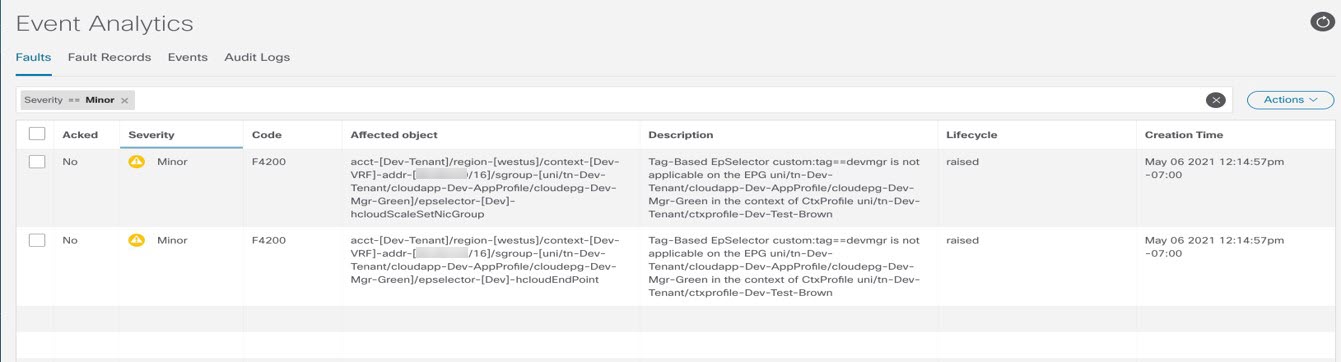
If an EPG is configured with tag-based endpoint selectors and is associated with the brownfield cloud context profile, then a fault will be raised saying that this EPG cannot be used.
Creating an EPG Associated With the Brownfield Cloud Context Profile Using the GUI
In this topic, you will be creating an EPG that is associated with the brownfield cloud context profile. For a better understanding of why you need to do this, see How EPGs are Associated With Brownfield Cloud Context Profiles Through VRFs.
Before you begin
Verify that you have completed all of the previous necessary configurations before going through these procedures, including:
Procedure
| Step 1 |
Determine if you are enabling the contract-based routing option or not for this brownfield VPC import.
|
||||||||||||||||||
| Step 2 |
Click the Intent icon ( The Intent menu appears. |
||||||||||||||||||
| Step 3 |
Click the drop-down arrow below the Intent search box and choose Application Management. A list of Application Management options appear in the Intent menu. |
||||||||||||||||||
| Step 4 |
From the Application Management list in the Intent menu, click Create EPG. The Create EPG dialog box appears. |
||||||||||||||||||
| Step 5 |
Enter the necessary general configurations for the EPG.
|
||||||||||||||||||
| Step 6 |
In the Endpoint Selectors field, define the subnet-based or specific IP-based endpoint selector corresponding to the Google Cloud brownfield site. For more information, see How EPGs are Associated With Brownfield Cloud Context Profiles Through VRFs. |
||||||||||||||||||
| Step 7 |
Click Save to save this EPG. |
||||||||||||||||||
| Step 8 |
Verify that the associated Google Cloud instance is shown in the Cisco Cloud Network Controller GUI. Click , then locate the associated Google Cloud instance.
|
||||||||||||||||||
What to do next
Configure a contract between the EPGs using the procedures provided in Creating a Contract Between the EPGs Using the GUI.
Creating a Contract Between the EPGs Using the GUI
In this topic, you will be creating a contract to be used from the EPG associated with the brownfield cloud context profile to the EPG associated with the greenfield cloud context profile. This is done to drive the programming of the route entries to the brownfield VPC CIDRs in the route table in the greenfield VPC side. This also drives the programming of all the security group rules on the greenfield VPC side to allow the packets to be sent to or received from these subnets defined on the EPG's endpoint selector.
Before you begin
Create an EPG associated with the brownfield cloud context profile using the instructions provided in Creating an EPG Associated With the Brownfield Cloud Context Profile Using the GUI.
Procedure
| Step 1 |
Click the Intent icon. The Intent menu appears. |
||||||||||||||||
| Step 2 |
Click the drop-down arrow below the Intent search box and choose Application Management. A list of Application Management options appear in the Intent menu. |
||||||||||||||||
| Step 3 |
From the Application Management list in the Intent menu, click Create Contract. The Create Contract dialog box appears. |
||||||||||||||||
| Step 4 |
Enter the appropriate values in each field as listed in the following Create Contract Dialog Box Fields table then continue.
|
||||||||||||||||
| Step 5 |
Click Save when finished. |
||||||||||||||||
| Step 6 |
In the main Create Contract window, click Configure EPG Communication. The EPG Communication Configuration window appears. |
||||||||||||||||
| Step 7 |
In the Contract area, click Select Contract. The Select Contract window appears. |
||||||||||||||||
| Step 8 |
Choose the contract that you just created from the list of contracts and click Select. You are returned to the EPG Communication Configuration window. |
||||||||||||||||
| Step 9 |
In the Provider EPGs area on the right side, click Add Provider EPGs. The Select Provider EPGs window appears. |
||||||||||||||||
| Step 10 |
Choose the EPG associated with the greenfield cloud context profile and click Select. You are returned to the EPG Communication Configuration window. |
||||||||||||||||
| Step 11 |
In the Consumer EPGs area on the right side, click Add Consumer EPGs. The Select Consumer EPGs window appears. |
||||||||||||||||
| Step 12 |
Choose the EPG associated with the brownfield cloud context profile and click Select. You are returned to the EPG Communication Configuration window. |
||||||||||||||||
| Step 13 |
Click Save. |
||||||||||||||||
What to do next
Complete the remaining configuration tasks in Google Cloud using the procedures provided in Completing the Remaining Configurations for the Brownfield VPC in Google Cloud.
Creating an EPG Associated With the Brownfield Cloud Context Profile Using the REST API
Procedure
|
Create a cloud EPG for the brownfield VPC. You will be creating a cloud EPG to allow an on-premises site or another cloud site to be able to send or receive the traffic to this brownfield VPC.
|
Completing the Remaining Configurations for the Brownfield VPC in Google Cloud
In these procedures, you will program the firewall rules to allow the security rules to send or receive packets from the external site endpoints or subnets in Google Cloud.
Before you begin
Verify that you have completed all of the previous necessary configurations before going through these procedures, including:
Procedure
| Step 1 |
In Google Cloud, navigate to . |
| Step 2 |
In the Firewall page, click CREATE FIREWALL POLICY or CREATE FIREWALL RULE to create new ingress and egress firewall rules to allow the security rules to send or receive packets from the external site endpoints or subnets. You must perform a manual configuration for the brownfield VPC, and the method that you use will vary depending on the firewall rules that you are configuring. |
| Step 3 |
Click SAVE when you have completed the configuration for the ingress or egress firewall rules.
|
Trademarks
THE SPECIFICATIONS AND INFORMATION REGARDING THE PRODUCTS REFERENCED IN THIS DOCUMENTATION ARE SUBJECT TO CHANGE WITHOUT NOTICE. EXCEPT AS MAY OTHERWISE BE AGREED BY CISCO IN WRITING, ALL STATEMENTS, INFORMATION, AND RECOMMENDATIONS IN THIS DOCUMENTATION ARE PRESENTED WITHOUT WARRANTY OF ANY KIND, EXPRESS OR IMPLIED.
The Cisco End User License Agreement and any supplemental license terms govern your use of any Cisco software, including this product documentation, and are located at: http://www.cisco.com/go/softwareterms.Cisco product warranty information is available at http://www.cisco.com/go/warranty. US Federal Communications Commission Notices are found here http://www.cisco.com/c/en/us/products/us-fcc-notice.html.
IN NO EVENT SHALL CISCO OR ITS SUPPLIERS BE LIABLE FOR ANY INDIRECT, SPECIAL, CONSEQUENTIAL, OR INCIDENTAL DAMAGES, INCLUDING, WITHOUT LIMITATION, LOST PROFITS OR LOSS OR DAMAGE TO DATA ARISING OUT OF THE USE OR INABILITY TO USE THIS MANUAL, EVEN IF CISCO OR ITS SUPPLIERS HAVE BEEN ADVISED OF THE POSSIBILITY OF SUCH DAMAGES.
Any products and features described herein as in development or available at a future date remain in varying stages of development and will be offered on a when-and if-available basis. Any such product or feature roadmaps are subject to change at the sole discretion of Cisco and Cisco will have no liability for delay in the delivery or failure to deliver any products or feature roadmap items that may be set forth in this document.
Any Internet Protocol (IP) addresses and phone numbers used in this document are not intended to be actual addresses and phone numbers. Any examples, command display output, network topology diagrams, and other figures included in the document are shown for illustrative purposes only. Any use of actual IP addresses or phone numbers in illustrative content is unintentional and coincidental.
The documentation set for this product strives to use bias-free language. For the purposes of this documentation set, bias-free is defined as language that does not imply discrimination based on age, disability, gender, racial identity, ethnic identity, sexual orientation, socioeconomic status, and intersectionality. Exceptions may be present in the documentation due to language that is hardcoded in the user interfaces of the product software, language used based on RFP documentation, or language that is used by a referenced third-party product.
Cisco and the Cisco logo are trademarks or registered trademarks of Cisco and/or its affiliates in the U.S. and other countries. To view a list of Cisco trademarks, go to this URL: www.cisco.com go trademarks. Third-party trademarks mentioned are the property of their respective owners. The use of the word partner does not imply a partnership relationship between Cisco and any other company. (1721R)
 Feedback