Using Your New CML System

Now that your Cisco Modeling Labs system is installed and licensed, you can start using it to simulate network topologies. In the next sections, you will create a lab by drawing the network topology. Then you will start the simulation. Once the lab simulation is running, you can connect to virtual nodes in the lab. When you're done with the lab, you can stop the simulation, preserving the lab for later use.

Note that sample labs are included with CML and may also be used to become familiar with the platform. Sample labs can be found under Tools > Sample Labs located on the menu bar. When using the included sample labs, note the topology size (node count), and select an appropriate topology based on your system's available resources. If you try to start a large topology simulation on a CML server that's using the minimum system requirements, it may return errors or make the nodes unusable. CML-Personal licensing constrains simulations to a maximum of 20 nodes.

Creating Your First Lab

Creating a Lab

Before you begin

Log into the CML web UI using an application user account. For example, you may use the initial user account created during the installation process. After logging in, you will see the Lab Manager page of the UI.

Procedure


Step 1

On the Lab Manager's menu bar, click Add Lab.

A new lab is created, and the tile for the lab will appear in the Lab Manager with a default name, such as Lab at Tue 14:30 PM.

Step 2

Optional: Hover over the lab tile and click the lab name to start editing.

Step 3

Optional: Enter a new lab name and press Enter to rename the lab.

You may edit the lab name at any time from the Lab Manager tile or in the Workbench's menu bar.

Adding Nodes to a Lab

Before you begin

Open the lab that you want to edit in the Workbench by clicking on its tile on the Lab Manager page.

Procedure


Step 1

Click the Add Nodes drawer in the Workbench to open it.

In a new lab or a lab with no nodes, the Add Nodes drawer will already be open by default.
Step 2

Drag-and-drop a node type from the Add Nodes drawer onto the lab to add a node of that type to the lab's network topology.

Step 3

Repeat the previous step for each node that you want to add to the lab.


Connecting Nodes in a Lab

Procedure


Step 1

In the Workbench, hover over the desired source node for the new connection to activate the action ring for the node.

Step 2

Press and hold the mouse button on the blue link button.

Note: if the mouse cursor changes to a cancel icon when you hover it over the link button on the action ring, the Workbench is indicating that that the source node has no more available interfaces. You will not be able to create any additional connections to or from this node until an existing interface is freed.

Step 3

While holding the mouse button, drag away from the source node to start creating a connection.

Step 4

Hover the mouse over the desired destination node for the connection and then release the mouse button.

The currently-selected node will be highlighted in blue.
The Workbench pops up an interface selection dialog.
Note: the currently selected node should be highlighted in blue. If the currently selected node is highlighted in red, and the mouse cursor changes to a cancel icon, the Workbench is indicating that the destination node has no more available interfaces. You will not be able to create any additional connections to or from this node until an existing interface is freed.
Step 5

Select the desired interface on the Source and Destination nodes in the dialog. Alternatively, you can just click the Use Next Available (interface) button, and the connection will be created with the first unused interface on each node.

Step 6

Repeat the previous steps for each connection that you want to create in the network topology.


Starting a Simulation

Before you begin

Open the lab that you want to start in the Workbench by clicking on its tile on the Lab Manager page.

Procedure


Step 1

First, ensure that no nodes are selected by clicking on an empty area of the Workbench.

Step 2

Optional: Select the Design tab at the bottom of the Workbench page.

Step 3

Optional: Click the Build Initial Bootstrap Configurations button in the Design panel.

You can also build configurations on an individual node by selecting the desired node and then clicking the Build Initial Bootstrap Configurations button.

CML generates a basic startup configuration for all nodes in the topology.
Step 4

Select the Simulate tab at bottom of the Workbench window.

Step 5

Click the Start button.

CML will start the simulation for the lab. Note that the Workbench will provide visual feedback, indicating each node's status. A node is finished booting and ready for use when the Workbench displays a green dot next to it.

Connecting to a Node's Console

Once a simulation is started, you may connect to the console or, for applicable nodes, the VNC server for a node.

Procedure


Step 1

Hover over the desired node to activate the node's action ring.

Step 2

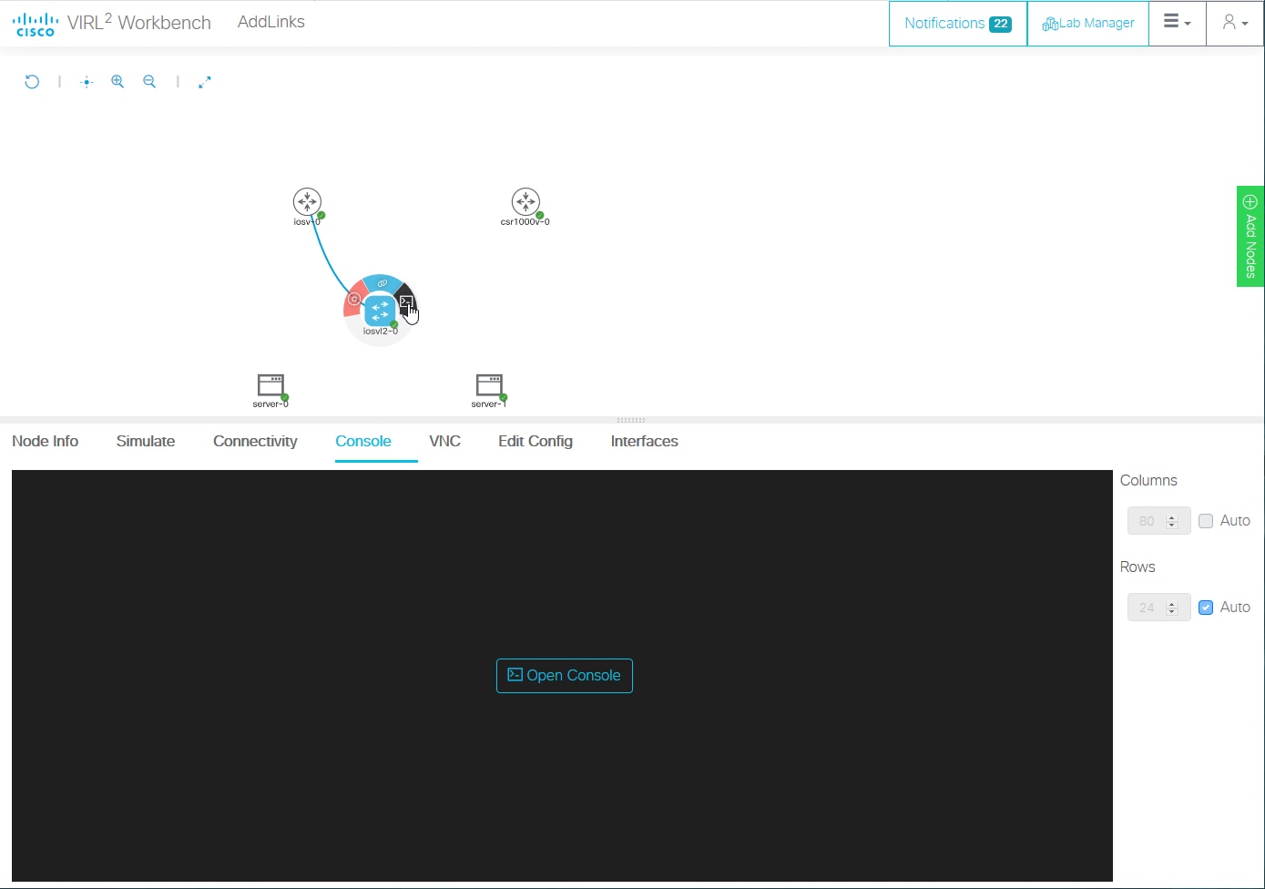
Click the Console button on the action ring to open the node's Console pane at the bottom of the Workbench.

Figure 1. Open Console Node Action

Screenshot: open console action on a node's action ring.
Step 3

Click the Open Console button in the Console pane at the bottom of the Workbench to activate the console connection.


Stopping a Simulation

Lab simulations are not stopped automatically. A lab simulation will continue to run and consume resources even if you close the Workbench page for a lab or log out of the UI.

Procedure


Step 1

First, ensure that no nodes are selected by clicking on an empty area of the Workbench.

Step 2

Select the Simulate tab at the bottom of the Workbench window.

Step 3

Click the Stop button.


CML will stop the simulation for this lab. The lab's nodes will be stopped, and the Lab Manager will no longer show this lab as running.