Cisco Modeling Labs User Guide, Release 1.0.1
Bias-Free Language
The documentation set for this product strives to use bias-free language. For the purposes of this documentation set, bias-free is defined as language that does not imply discrimination based on age, disability, gender, racial identity, ethnic identity, sexual orientation, socioeconomic status, and intersectionality. Exceptions may be present in the documentation due to language that is hardcoded in the user interfaces of the product software, language used based on RFP documentation, or language that is used by a referenced third-party product. Learn more about how Cisco is using Inclusive Language.
- Updated:
- November 14, 2014
Chapter: Design a Topology
Design a Topology
Design a Topology Overview
The design phase is the initial step in creating a network topology. During the design phase, you will perform the tasks described in the following sections.
Topology Nodes and Connections
The topology you design consists of nodes and connection functions. Refer to the section Navigating Within the Cisco Modeling Labs Client for additional information about how to select and edit nodes and connection functions.
Topology Nodes
Cisco Modeling Labs provides the Cisco IOSv node subtype. Additional node types are available and can be installed by the system administrator via the User Workspace Management interface. See the User Workspace Management chapter in the Cisco Modeling Labs Corporate Edition System Administrator Installation Guide, Release 1.0.1.
| Node Name | Node Type |
|---|---|
| Cisco IOSv | Router node. Runs a Cisco IOS operating system. |
| Server | Server node. Runs a Linux operating system. |
| Cisco IOS XRv | Router node. Runs a Cisco IOS XR operating system. (Available separately.) |
| Cisco CSR1000v | Router node. Runs a Cisco CSR 1000 operating system. (Available separately.) |
A node subtype is a virtual machine that runs on top of OpenStack, which itself is running in a Linux virtual machine that is running on top of VMware software. Because the node is virtual, specific hardware is not emulated. For example, there are no power supplies, no fans, no ASICs, and no physical interfaces. For all router nodes, the interface type is a Gigabit Ethernet network interface. A server node has an Ethernet network interface.
You can choose an image and image flavor for each node type. Refer to the User Workspace Management chapter in the Cisco Modeling Labs Corporate Edition System Administrator Installation Guide, Release 1.0.1 for information on how to access the VM Image and the VM Flavor choices. In most cases, you need not select an image and flavor. By default, the node subtype is associated with an image and flavor that runs with the topology.
| VM Image Name | Used For |
|---|---|
| server | Server node |
| CSR1000v | Cisco CSR1000v node |
| IOSv | Cisco IOS node |
| IOS XRv | Cisco IOS XR node |
| VM Flavor Name | Used For |
|---|---|
| m1_tiny | Linux server |
| m1_small | Linux server |
| m1_medium | Linux server |
| m1_large | Linux server |
| m1_xlarge | Linux server |
| server | Linux server |
| CSR1000v | Cisco CSR 1000v node |
| IOS XRv | Cisco IOS XR node |
| IOSv | Cisco IOS node |
Each Linux flavor provides a different amount of memory and CPU allocated to the server.
Connection Functions
Cisco Modeling Labs provides the connection functions shown in the following table.
| Connection Type | Description |
|---|---|
| Connection | Creates a connection between two interfaces. Interfaces are created in the node to support a connection. Any unused interfaces present are automatically assigned. All the interfaces in router nodes are represented as Gigabit Ethernet interfaces. Multiple parallel connections are supported. |
| Multipoint Connection | Creates a multipoint connection point. Multiple nodes can connect to a multipoint connection. |
| Layer 3 External (SNAT) | Creates a Layer 3 external connection point using static network address translation (SNAT). This external connection point allows connections outside of Cisco Modeling Labs to connect to the topology. |
| Layer 2 External (Flat) | Creates a Layer 2 external connection point using FLAT. This external connection point allows connections outside of Cisco Modeling Labs to connect to the topology. |
| Type | Description |
|---|---|
| Site | Creates a site that can contain one or more nodes, and additional groups of nodes. A site is a group of nodes and you can create multiple site layers. |
Create a Topology Project
Cisco Modeling Labs client provides a project folder and a sample topology that you can work with in addition to creating your own project and topology.
A topology project is a folder in which multiple topology files are stored. If you create many different topologies, you can set up different projects for the topologies you create.
The three methods available for creating a topology project are discussed in the following sections.
Before you begin the task of creating a topology project, you must complete the installation steps for your system and set up the web services profile for the Cisco Modeling Labs client. Refer to the Cisco Modeling Labs Corporate Edition System Administrator Installation Guide, Release 1.0.1. See Navigating Within the Cisco Modeling Labs Client for information on how to navigate the perspectives and views, and information about the menu bars, toolbars, and editors. The navigation information is also available in the online help.
In addition, understand how:
Method 1: Create a Topology Project from the Menu Bar
Method 2: Create a Topology Project from the Projects View
Method 3: Create a Topology Project from the Toolbar
What to Do Next
Create a new topology file.
Create a Topology
A topology project folder must exist.
There are several methods for creating a topology. These are discussed in the following sections.
Method 1: Create a Topology from the Menu Bar
Method 2: Create a Topology from the Projects View
Method 3: Create a Topology from the Toolbar
What to Do Next
Place the nodes.
Place the Nodes on the Canvas
| Step 1 | Click a node type, which is under the Nodes heading in the Palette view. | ||||
| Step 2 | Click the canvas
at each point where you want a node. You can also drag the nodes on the canvas
to position them. You can then arrange the nodes using several methods:
|
What to Do Next
Create connections and interfaces.
Create Connections and Interfaces
Nodes must be in place on the canvas of the Topology Editor.
| Step 1 | Click Connection in the Tools view. | ||||
| Step 2 | Click the first node. | ||||
| Step 3 | Click the next
node to create the connection.
| ||||
| Step 4 | Repeat Step 2 and
Step 3 until all the connections are in place.
|
What to Do Next
Create multipoint connections (optional).
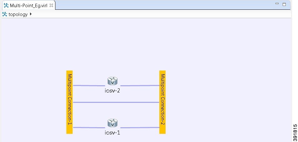
Create Multipoint Connections
Multipoint connections are used in BUS topologies where all the nodes are connected to a single transmission medium. This acts as the backbone of the connection and links all the nodes in the network. For example, for four nodes to be directly connected to one another, 12 separate interface connections are needed, three in each router, to fully connect each router to the other. By using a multipoint connection, each router has one connection to the multipoint node.
A topology file with the extension .virl must exist. Router nodes or server nodes are placed on the canvas. Optionally, connections may exist between nodes.
| Step 1 | In the General view, click Multipoint Connection. | ||||
| Step 2 | Click the area on the canvas where you want the multipoint connection node to appear. | ||||
| Step 3 | In the Tool view, click Connect. | ||||
| Step 4 | On the canvas,
click the multipoint connection node then click an end node. A connection
appears.
Continue clicking
multipoint-node combinations until all connections are made.
|
What to Do Next
Create a Site
A site is a container that can hold one or more nodes. It is used to group multiple nodes within the same site, which provides a degree of hierarchy and simplifies the topology view.
A node interface within a site can connect to another node interface in the same site or to a node interface located in a different site. A connection cannot start on a node and terminate on a site. Sites can be nested, forming a hierarchical structure.
One or more nodes should be on the canvas.
| Step 1 | In the General view, click Site. |
| Step 2 | Click an area on the canvas to place the site. |
| Step 3 | Shift-click the nodes that you want in the site, or click and drag a selection window around the nodes. |
| Step 4 | To view the site,
select the site name from the drop-down list under the Topology tab.
A topology site tab opens and displays the site view. The drop-down list under the Topology tab displays the site hierarchy as a navigation trail. To open a site view, double-click on the site. The following figure shows the navigation trail selections for Site 1 and Site 2.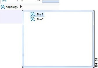 |
| Step 5 | To ungroup the site, click the site icon and choose . |
| Step 6 | To connect node
interfaces between Site 1 and Site 2:
|
| Step 7 | To delete a node from a site:
|
| Step 8 | To delete a site from a topology:
|
What to Do Next
Continue designing the topology.
View the Topology on a Map
The topology view is a schematic diagram. It shows the nodes and connections arranged in a logical fashion, or represents a design that is easy to view. When you create a map view, you can move the nodes such that they represent a physical location, for example, the locations of all router nodes in a city. Moving nodes on a map view does not change their location in the topology view.
Within a topology file, each node is represented by two sets of coordinates. The location coordinates define the node placement in the topology view. The map coordinates define node placement on the map view, by latitude and longitude.
The map view uses the MapQuest database for map display.
| Step 1 | With the topology view active, select . Alternatively, you can click the Show Map Background tool in the toolbar. |
| Step 2 | Before you move a
node, select the desired map location.
|
| Step 3 | Click and drag the
nodes into position on the map.
When you click and drag a node, the map coordinates are added to the .virl file and the node becomes a part of the map view. When you open the map view again, the map location with the nodes is displayed. |
| Step 4 | Continue to click and drag the nodes into position on the map view. |
| Step 5 | Click the Show Map Background tool in the toolbar to revert to the topology view. Note that the nodes in the topology view are in their original layout. |
 Feedback