This is a post-installation document intended to cover the steps required to get up and running with Cisco Crosswork Network Controller and start using the user interface (UI) to execute the supported use cases.
This document is intended for experienced network administrators and assumes familiarity with:
-
Networking technologies and protocols (BGP-LS, IGP (OSPF and IS-IS), PCEP, model-driven telemetry, and so on)
-
Segment Routing Path Computation Element (SR-PCE) functionality
-
Cisco Network Services Orchestrator (Cisco NSO) functionality
-
Segment routing (SR-TE) and SR policy provisioning
-
Layer 2 and layer 3 VPN topology and provisioning concepts
For an overview of the steps that need to be taken to get started with Cisco Crosswork Network Controller and links to the relevant sections, see Getting Started Overview.
This document contains the following sections:
Introduction to the Cisco Crosswork Network Controller and its Components
Cisco Crosswork Network Controller is an integrated solution combining Network Services Orchestrator (NSO), Segment Routing Path Computation Element (SR-PCE), and Crosswork applications with a common UI and API. The solution enables you to proactively manage your end-to-end networks and provides intent-based and closed-loop automation solutions to ensure faster innovation, good user experience, and operational excellence.
-
Visualize network and service inventory.
-
Provision segment routing (SR) traffic engineering policies for services with explicit SLAs by specifying optimization objectives (latency/IGP/TE metric minimization) and constraints (affinities, disjoint paths, bandwidth).
-
Provision L2VPN and L3VPN services with associated SLAs.
-
Collect realtime performance information and optimize the network to maintain the SLAs. Tactically optimize the network during times of congestion.
-
Benefit from realtime bandwidth on demand and bandwidth optimization services.
-
Use the APIs to extend the solution based on your specific needs.
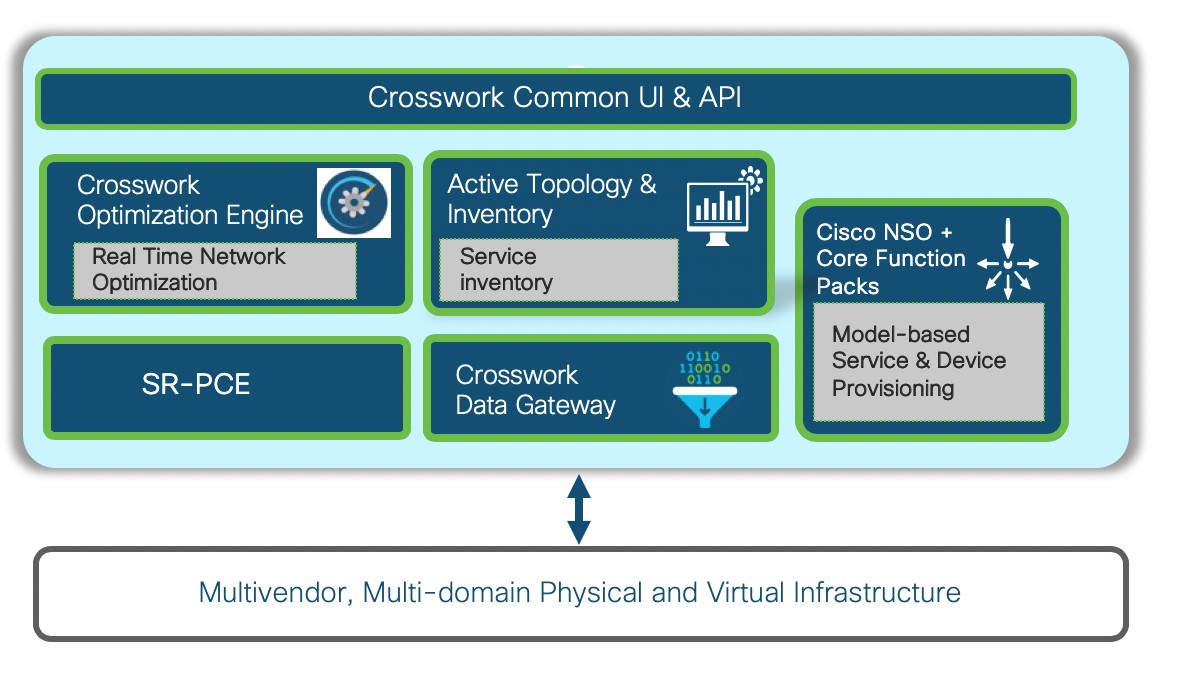
Cisco Network Services Orchestrator (NSO)
Cisco Network Services Orchestrator (NSO) is a proven multivendor, cross-domain automation platform that links business intent to an organization’s underlying physical and virtual infrastructure. Cisco NSO has been shaped by nearly a decade of helping tier-1 service provider customers to automate everything from simple device turn-up, to cross-domain automation, to sophisticated full lifecycle service management on a multivendor network.
-
Segment Routing Traffic Engineering (SR-TE) Core Function Pack enables provisioning of segment routing policies with SLA, for example, bandwidth and latency.
- Services Sample Function Pack enables Layer 2 and Layer 3 VPN service provisioning on routers, leveraging SR policies set up using the SR-TE Core Function Pack. The sample function pack can be extended and customized for customer-specific requirements.
-
Telemetry Function Pack enables telemetry configuration on the routers.
Segment Routing Path Computation Element (SR-PCE)
Cisco Crosswork Network Controller uses the combination of telemetry and Cisco Segment Routing Path Computation Element (SR-PCE) to analyze and compute optimal SR policy paths. Cisco SR-PCE runs on the Cisco IOS XR operating system. SR-PCE provides stateful PCE functionality that helps control and move SR policies to optimize the network. PCE describes a set of procedures by which a Path Computation Client (PCC) can report and delegate control of head-end tunnels sourced from the PCC to a PCE peer. The PCC and PCE establish a Path Computation Element Communication Protocol (PCEP) connection that SR-PCE uses to push updates to the network.
Cisco Crosswork Data Gateway
Networks maintain a large amount of data that spans thousands of devices. Cisco Crosswork Network Controller uses a data collection service along with Cisco Crosswork Data Gateway (Crosswork CDG) to collect and manage this data. Crosswork Data Gateway collects physical (e.g., ENTITY-MIB, IF-MIB) and logical (e.g., LAG, VRF) objects from network devices and publishes collected data for the northbound analytics applications. Data from network devices is collected using multiple protocols including CLI, SNMP, and Model Driven Telemetry.
Cisco Crosswork Optimization Engine
Cisco Crosswork Optimization Engine provides real-time network optimization allowing operators to effectively maximize network capacity utilization, as well as increase service velocity. Leveraging real-time protocols such as BGP-LS and Path Computation Element Communication Protocol (PCEP), SR-PCE and Crosswork Optimization Engine enable closed-loop tracking of the network state, reacting quickly to changes in network conditions to support a self-healing network.
Cisco Crosswork Active Topology
Cisco Crosswork Active Topology enables visualization of topology and services on logical and geographical maps.
Crosswork Common UI and API
Crosswork Common UI provides an integrated user interface for device onboarding/management, service provisioning using NSO, SR policy visualization using Cisco Crosswork Optimization Engine, and service inventory and topology visualization using Cisco Crosswork Active Topology. The Crosswork API provides a RESTCONF interface to facilitate integration with higher level controllers/orchestrators.
Getting Started Overview
|
Task |
Refer to... |
|---|---|
|
Log into the GUI. |
|
|
Create credential profiles |
|
|
Add Cisco SR-PCE and Cisco NSO providers. |
|
|
Manage Cisco Crosswork Data Gateway servers. |
|
|
Add users and user roles. |
|
|
Create device tags. |
|
|
Add devices to the inventory so that they can be managed. Devices can be added in bulk by importing a CSV file or by auto-onboarding them. Devices can also be added individually through the UI. |
|
|
Set display preferences for your maps. |
|
|
Enable and configure bandwidth on demand and/or bandwidth optimization functionality. |
Log In and Log Out
To log into the web UI, enter the following in your web browser's address bar:
https://<hypervisor_server_IP_adddress>:30603/
In the displayed login window, enter the username and password configured during installation and click Log In.
Upon first-time access, some browsers display a warning that the site is untrusted. When this happens, follow the prompts to add a security exception and download the self-signed certificate from the Cisco Crosswork Network Controller server. After you do this, the browser accepts the server as a trusted site in all future login attempts.
To log out, click ![]() in the top right of the main window and choose Log out.
in the top right of the main window and choose Log out.
Create Credential Profiles
 Note |
SSH and SNMP credentials are mandatory for onboarding devices and synchronizing with the NSO provider. |
Follow the steps below to create a new credential profile. You can then use the profile to apply credentials consistently when you add new devices or providers. You can add as many protocols and corresponding credentials to the profile as you want.
If you have many credential profiles to add, you may find it more efficient to put the information in a CSV file and import the file. See Import Credential Profiles.
When creating device credential profiles that contain SNMP credentials, Cisco recommends that the profile contain credentials for the version of SNMP actually enabled on the device, and that version only. For example: If SNMPv3 is not enabled in the device configuration, do not include SNMPv3 credentials in the device credential profile.
If you plan to use the import and export features and CSV files to create credential profiles in bulk, please note that:
-
All the characters in each password or community string entry in every credential profile exported to a CSV file are replaced with asterisks.
-
You cannot import credential profiles if the passwords and community strings in the CSV file are blank (see Import Credential Profiles).
To maintain network security, Cisco recommends that you use asterisks in place of real passwords and community strings in any CSV file you plan to import. After the import, you can edit the credential profile to replace the asterisks with actual passwords and community strings.
Procedure
| Step 1 |
From the main menu, choose . |
||||||||||||||||||
| Step 2 |
Click |
||||||||||||||||||
| Step 3 |
In the Profile Name field, enter a descriptive profile name. The name can contain a maximum of 128 alphanumeric characters, plus underscores ("_") or hyphens ("-"). No other special characters are allowed. If you will have many credential profiles, make the name as informative as possible because that information will be displayed on the Credential Profiles panel. |
||||||||||||||||||
| Step 4 |
Select a protocol from the Connectivity Type dropdown. |
||||||||||||||||||
| Step 5 |
Complete the credentials fields described in the following table. The required and optional fields displayed will vary with the connectivity type you chose. The values you enter must match the values configured on the device.
|
||||||||||||||||||
| Step 6 |
(Optional) Click + Add Another and repeat the above steps, as needed, for all other protocols and corresponding credentials you want to add to this credential profile. |
||||||||||||||||||
| Step 7 |
Click Save. |
Import Credential Profiles
Note |
SSH and SNMP credentials are mandatory for onboarding devices and synchronizing with the NSO provider. |
Importing credential profiles from a CSV file adds any profiles not already in the database. You cannot import a credential profile that already exists.
If you are re-importing a credential profile CSV file that you previously exported and modified, remember that all the passwords and community strings in the exported credential profile CSV file are replaced with asterisks. You cannot re-import an exported credential profile CSV file with blank passwords. To maintain security, Cisco recommends that you use asterisks in place of real passwords and community strings in the CSV file. After the import, you can edit the credential profile to replace the asterisks with actual passwords and community strings.
Procedure
| Step 1 |
From the main menu, choose . |
| Step 2 |
Click |
| Step 3 |
If you have not already created a credential profile CSV file to import: |
| Step 4 |
Click Browse to navigate to the CSV file you just created and then click Open to select it. |
| Step 5 |
With the CSV file selected, click Import. |
Configure Providers
Cisco Crosswork Network Controller uses Cisco SR-PCE and Cisco NSO providers for various functions, including inventory collection, route segmentation, configuration maintenance, route calculation, and service provisioning. Providers must be added to Cisco Crosswork Network Controller so that their connectivity details are saved and made available to the various components for interaction purposes.
Follow the instructions in these sections to add the required providers:
Add Cisco NSO Providers
The Cisco Network Services Orchestrator (Cisco NSO) provider supplies the following functionality within Cisco Crosswork Network Controller:
-
Provisioning of segment routing (SR) policies. The Cisco NSO core function pack provides SR policy provisioning capability in Cisco Crosswork Network Controller.
-
Provisioning of Layer 2 and Layer 3 services running over SR-TE (ODN or preferred path). Cisco NSO provides sample function packs for provisioning of these services, allowing the services to be instantiated "as-is" or extended to meet specific needs using the APIs.
-
Device management and configuration maintenance services.
Note |
The NSO sample function packs provide example implementations as a starting point for VPN service provisioning functionality in Cisco Crosswork Network Controller. The intention is for customers to work with a Cisco Customer Experience representative to adapt these sample function packs to their specific networks and requirements. Although these implementations can be used "as is" to provision flat Layer 2 and Layer 3 VPN services using the GUI or API, they are not guaranteed to be complete and fully tested, and they are not products supported by Cisco. |
This release of Cisco Crosswork Network Controller supports only one instance of Cisco NSO as a provider.
Follow the steps below to add (through the UI) a Cisco NSO provider for Cisco Crosswork Network Controller. Note that you can import several providers at the same time by preparing a CSV file with the details of all the providers and importing it into Cisco Crosswork Network Controller.
Before you begin
-
Create a credential profile for the Cisco NSO provider (see Create Credential Profiles).
Know the name you want to assign to the Cisco NSO provider.
-
Know the Cisco NSO NED device models and driver versions used in your topology.
Note
You can find the Cisco NSO and NED versions using theversionandpackage-versioncommands, as shown in the below examples:nso@nso-virtual-machine:~$ ncs --version 5.2.03admin@ncs> show packages package package-version NAME PACKAGE VERSION ----------------------------------------------- cisco-iosxr-cli-7.13 7.13.9
-
Know the Cisco NSO server IP address.
Procedure
| Step 1 |
From the main menu, choose . |
| Step 2 |
Click |
| Step 3 |
Enter the following values for the Cisco NSO provider fields: |
| Step 4 |
Under Provider Properties, enter a Provider Key of forward and a Property Value of true. |
| Step 5 |
When you have completed entries in all of the required fields, click Save to add Cisco NSO as a provider. |
Add Cisco SR-PCE Providers
Cisco Segment Routing Path Computation Elements (Cisco SR-PCE) providers supply device discovery, management, configuration-maintenance and route-calculation services to Cisco Crosswork Network Controller. At least one SR-PCE provider is required in order to learn and discover SR policies, Layer 3 links, and devices.
Follow the steps below to add (through the UI) up to two instances of Cisco SR-PCE as providers for Cisco Crosswork Network Controller.
Before you begin
-
Create a credential profile for the Cisco SR-PCE provider (see Create Credential Profiles). This should be a basic HTTP text-authentication credential (currently, MD5 authentication is not supported). If the Cisco SR-PCE server you are adding does not require authentication, you must still supply a credential profile for the provider, but it can be any profile that does not use the HTTP protocol.
-
Know the name you want to assign to the Cisco SR-PCE provider. This is usually the DNS hostname of the Cisco SR-PCE server.
-
Know the Cisco SR-PCE server IP address.
-
Determine whether you want to auto-onboard the devices that Cisco SR-PCE discovers and, if so, whether you want the new devices to have their management status set to unmanaged when added. For more information, see Auto-Onboard Devices.
-
For high availability, ensure that you set up two separate Cisco SR-PCE providers with unique names and IP addresses, but with matching configurations .
Procedure
| Step 1 |
From the main menu, choose . |
| Step 2 |
Click |
| Step 3 |
Enter the following values for the Cisco SR-PCE provider fields: |
| Step 4 |
When you have completed entries in all of the required fields, click Save to add the SR-PCE provider. |
| Step 5 |
Confirm that the SR-PCE provider shows a green Reachability status without any errors. |
Note |
It is not recommended to modify auto-onboard options once set. If you need to modify them, do the following:
|
Manage Cisco Crosswork Data Gateway Servers
Networks maintain a large amount of data that spans thousands of devices. Cisco Crosswork Network Controller uses a data collection service along with Cisco Crosswork Data Gateway to collect and manage this data. Cisco Crosswork Data Gateway collects physical (e.g., ENTITY-MIB, IF-MIB) and logical (e.g., LAG, VRF) objects from network devices and publishes collected data for the northbound analytics applications.
Note |
More complicated approaches for resource optimization and dynamic assignment of tasks are possible and if desired, we recommend working with the Cisco Customer Experience team to design the behavior. |
After installing the instances of Cisco Crosswork Data Gateway, you must generate an enrollment package and then enroll each instance with Cisco Crosswork Network Controller. See the following sections:
Access Cisco Crosswork Data Gateway Through vCenter
Follow these steps to log in via vCenter:
Procedure
| Step 1 |
Locate the VM in vCenter and then right click and select Open Console. The Cisco Crosswork Data Gateway flash screen comes up. |
| Step 2 |
Enter username ( |
Generate An Enrollment Package
Every Cisco Crosswork Data Gateway instance must be identified by means of an immutable identifier. This requires generation of a Cisco Crosswork Data Gateway enrollment package. The enrollment package can be generated during installation by supplying OVF parameters or by using the Export Enrollment Package option from the interactive menu in the console.
The enrollment package is a JSON document created from the information obtained through the OVF template populated by the user during installation. It includes the all necessary information about Cisco Crosswork Data Gateway required for registering, such as Certificate, UUID of the Cisco Crosswork Data Gateway instance, and metadata like Cisco Crosswork Data Gateway instance name, creation time, version info, and so on.
If you opted not to export the enrollment package during install, then you must export it before you can enroll the Cisco Crosswork Data Gateway instance with Cisco Crosswork Network Controller. The steps to do so are described in Export Enrollment Package.
Note |
The enrollment package is unique to each Cisco Crosswork Data Gateway instance. |
A sample enrollment package JSON file is shown below:
{
  "name": "dg116.cisco.com",
  "description": "CDG Base VM for Automation",
  "profile": {
    "cpu": 8,
    "memory": 31,
    "nics": 3
  },
  "interfaces": [
    {
      "name": "eth0",
      "mac": "00:50:56:9e:09:7a",
      "ipv4Address": "<ip_address>/24"
    },
    {
      "name": "eth1",
      "mac": "00:50:56:9e:67:c3",
      "ipv4Address": "<ip_address>/16"
    },
    {
      "name": "eth2",
      "mac": "00:50:56:9e:83:83",
      "ipv4Address": "<ip_address>/16"
    }
  ],
  "certChain": [
    "MIIFezCCA2OgAwIBAgIJAIP1aTyDBd/MMA0GCSqGSIb3DQEBDQUAMFQxCzAJBgNVBAYTAlVTMQswCQYDVQQIDAJDQTERMA8GA1UEBwwIU2FuIEpvc2UxCzAJBgNVBAoMAkRHMRgwFgYDVQQDDA9kZzExNi5jaXNjby5jb20wHhcNMTkxMDI4MTQwMDE0WhcNMzkxMDIzMTQwMDE0WjBUMQswCQYDVQQGEwJVUzELMAkGA1UECAwCQ0ExETAPBgNVBAcMCFNhbiBKb3NlMQswCQYDVQQKDAJERzEYMBYGA1UEAwwPZGcxMTYuY2lzY28uY29tMIICIjANBgkqhkiG9w0BAQEFAAOCAg8AMIICCgKCAgEAuizEa5R/BERI5G7mc0XD23NKFg6y8YzL1IFn7r1xUwP13mmOZq1WjNowhCecVSV9X+a2Ozcs69S2zJe6lsV8hV9g7+maTiE1KPrsyO6oAGvyA5RE/BfbR2LgR5mnsYK/GqInfqnR0/W6C038Godp2gRo6V+C3cgdtcGBaTegQuHpDqzQFLOxmV25+XFAyWlorb6PLDXU1nihs1kOYZbAZrqsBod+CVBVaj9ne809T6SfaiFiOiZ7pPDMotcDnivfQl+/n2/JvqS0SRcFbua5yirwKqCdRoK1JRnMZS1TR6aA9eex24Dc/xzKK+PBI+vNstX1u3JyoisNayc3GgFBgHXP/TqmEF2+EhuxnonY0FG37eYz0AWjbzc57VApeZuHd4pC2jwwe7ln8NxnVqnGqHUSa3Lsz6/NLsCKs89qyvg+0GqMiB8bjWdjP+/I7LOCpaUFK+NaiIoDrHGy2JtbbpHtWqPWH80TM1hYbd8osznr4+CvAeHp3xB69alBrM/QNYHP7wmI8z7Ok4sAFIcprLS9Vhw9dT+EYL2jTfADA/g2vhUKc4Ip9NTdaQfMUyDhMp85Rliu4XvCOS6EjYfB92VouYnKRtA/vAgImTYkCVxifZ2CKPfyaI1SA6VaHDx2APVLFC9TjEWTkAvYU6tIAsIj0JMAPaWFZiBdsym4aN8CAwEAAaNQME4wHQYDVR0OBBYEFBTwQocZxTkwKsMrdrotzAk/ztZgMB8GA1UdIwQYMBaAFBTwQocZxTkwKsMrdrotzAk/ztZgMAwGA1UdEwQFMAMBAf8wDQYJKoZIhvcNAQENBQADggIBACRJEeEO6zpbpV16O/pEDBmxz6KmM1XTLyNtnJrhtJ7EVcWDPWut6NgxsuETVDT+0BSr+/br2IVK1Gz8mi2PcGSuJKG3pATeg8XrdCYcnyWN2f7U3WXBQrX9a4GYNE0NPTjLmcm0+1zahQi2mNE6UHcf7R+CTP/CJYspcwWGqT127m2kWYyWBZX544dI+tX/InWnkMNP0AAXAOTJrGyNV+DRqoLD8/gjl1Zu+J6tkajenJv/RuS8FBqdXBUlCmPeaHgATsROYI+ZtFeBZC3051xNnSDFY+M4/6h+h2c6KTrQERLVZx15yRCZHZ/B3q/SLPiaMOkVuwn1SwMXvR+V67x2cxbmM1lgeKmAcyKeP4RMJmcpvZYQEaCJxKSoLh9Fp03wxLJbJS18w2J8l+hi7eYQ3PMKKhCGEepZslRCKRvW/ecIvV37EPI1g9Ecr1ea9q5tmrjqpdXbD0OMms057HY0/UQggLd939BuwWE1ryy6QDEc7I1edfvmovE9Sw+vdGGvikWONfsI4vCbBd6QCRl+f5pbOwYanln5YUnI3fRhVQ5OsrhstVkCzAMtQxr88Q4junWrduzFyHn36cE7qDBk7A1umeh04Pv1jZMrduBT2J9mD2A4VyGo2YE0VWvrd/m8R7QsLPBYfRZzYKJNSBeLlxl3V4j37aGGblL7uZFD"
  ],
  "version": "1.1.0 (branch dg110dev - build number 152)",
  "duuid": "d58fe482-fdca-468b-a7ad-dfbfa916e58b"
}
Export Enrollment Package
To enroll the Cisco Crosswork Data Gateway with Cisco Crosswork Network Controller, you must have a copy of the enrollment package on your local computer.
Follow these steps:
Procedure
| Step 1 |
Log into the Cisco Crosswork Data Gateway Base VM. |
||
| Step 2 |
From the Main Menu, select 1 Export Enrollment Package and click OK. 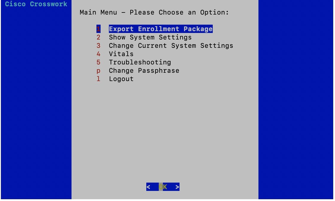 |
||
| Step 3 |
Enter the SCP URI for exporting the enrollment package and click OK.
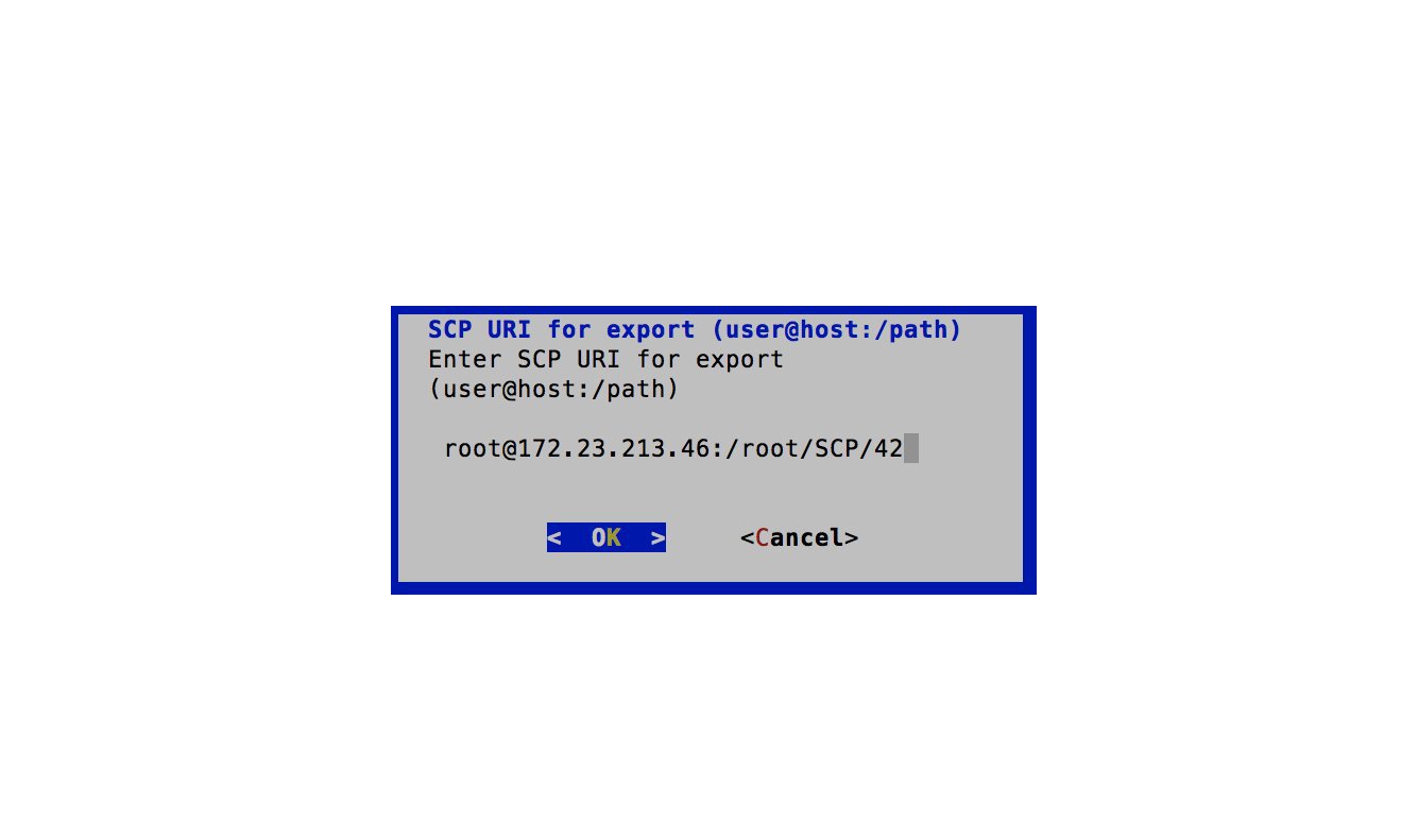 |
||
| Step 4 |
Enter the SCP passphrase (the SCP user password) and click OK. 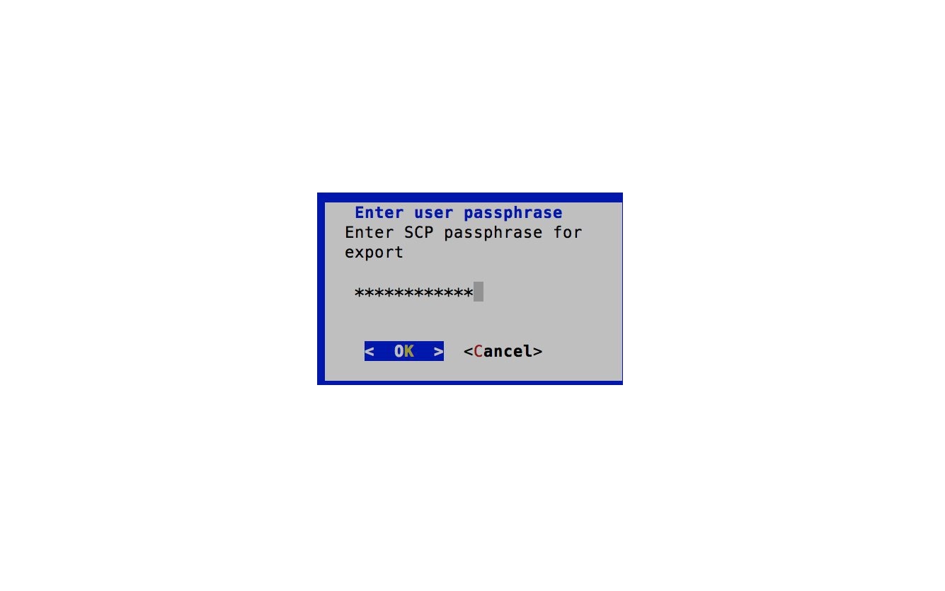 The enrollment package is exported. |
||
| Step 5 |
If you could not copy the enrollment package directly to your local computer, manually copy the enrollment package from the SCP server to your local computer. |
||
| Step 6 |
Proceed with importing the Controller Signing Certificate file. |
Enroll Cisco Crosswork Data Gateway
Procedure
| Step 1 |
Log into Cisco Crosswork Network Controller. |
| Step 2 |
From the Main Menu, select Admin > Data Gateway Management. The Data Gateway Management page opens. |
| Step 3 |
Click the Add button. The Enroll New Data Gateway dialog opens. |
| Step 4 |
Click Browse and navigate to the folder to which you copied the enrollment package and select it. |
| Step 5 |
Select the Data gateway admin state in which you want to bring up the Cisco Crosswork Data Gateway:
The Enroll New Data Gateway dialog displays a summary of the selected enrollment package:
It also displays additional details:
|
| Step 6 |
Click Enroll. Once you click Enroll, a dialog pops up asking if you want to attach devices now or later. It is recommended to choose Later as devices must only be attached once the operational state of the Cisco Crosswork Data Gateway instance is Up. See Attach a Device to a Cisco Crosswork Data Gateway Instance. 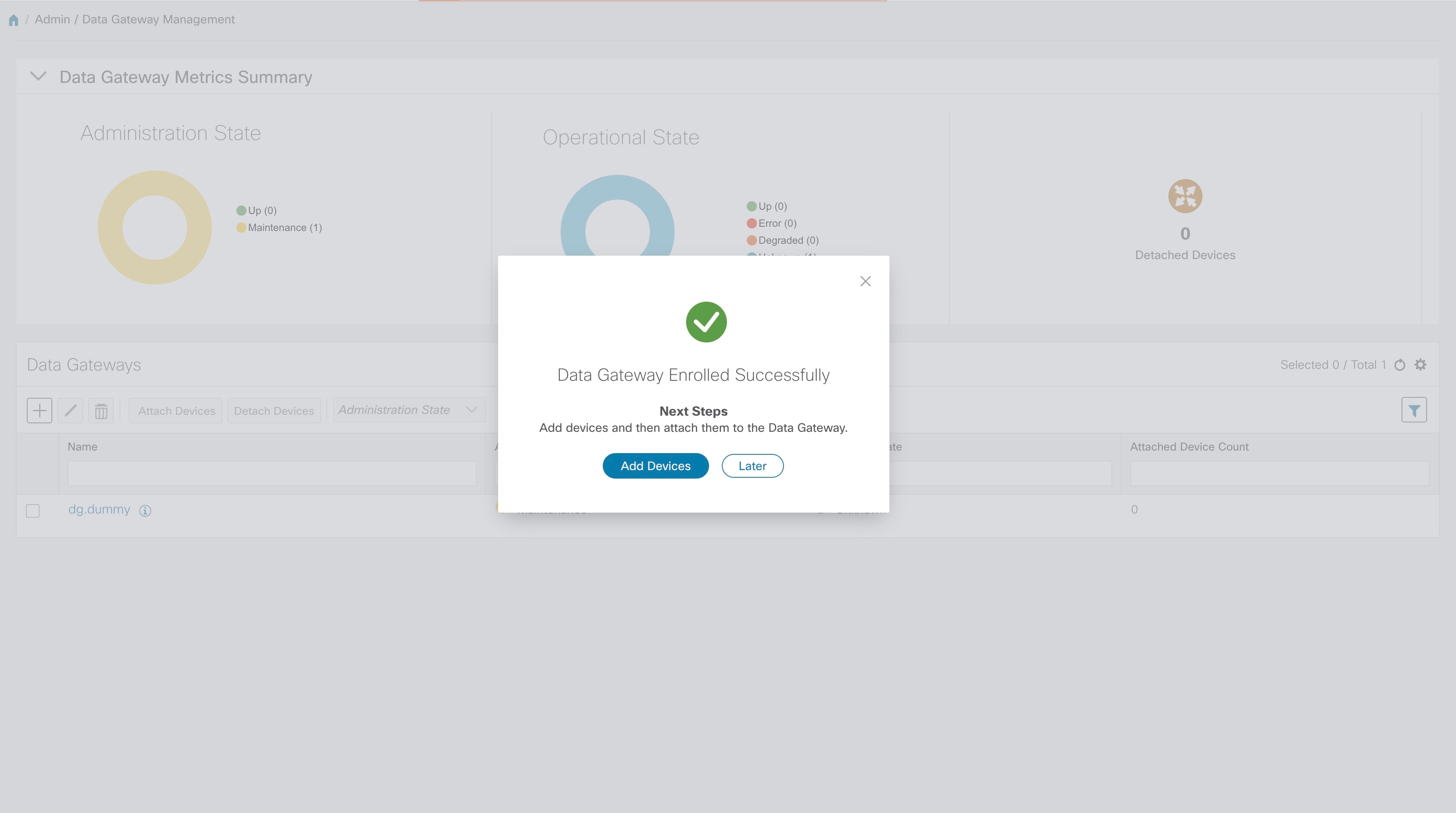 |
What to do next
The Operational Status of a Cisco Crosswork Data Gateway instance is shown as "Degraded" until it establishes a connection with Cisco Crosswork Network Controller and downloads collector binary files. While it depends on the bandwidth between the Cisco Crosswork Data Gateway instance and Cisco Crosswork Network Controller, this operation typically takes less than 5 minutes. Click the ![]() icon in the Data Gateways pane to refresh the pane to reflect the latest operational status of the Cisco Crosswork Data Gateway instance and wait for it to become Up. If the Cisco Crosswork Data Gateway instance fails to enroll, contact Cisco CX for assistance.
icon in the Data Gateways pane to refresh the pane to reflect the latest operational status of the Cisco Crosswork Data Gateway instance and wait for it to become Up. If the Cisco Crosswork Data Gateway instance fails to enroll, contact Cisco CX for assistance.
Cisco Crosswork Data Gateway Authentication and Bootstrap
During the enrollment process, the enrollment package is uploaded to the controller application, i.e., Cisco Crosswork Network Controller, which then instantiates a new Cisco Crosswork Data Gateway instance in its database and waits for a "first-sign-of-life" from the Cisco Crosswork Data Gateway.
Session Establishment
Once the connectivity is established, the Cisco Crosswork Data Gateway instance confirms the identity of the controller and offers its own proof of identity via signed certificates during this initial connection.
Download of Configuration Files
Once the session is established, Cisco Crosswork Data Gateway downloads the following configuration files:
|
boot-config |
A json response created by Crosswork that contains a list of services (docker containers) and functional images should be downloaded on that particular Cisco Crosswork Data Gateway instance. |
|
docker-compose |
A YAML file that contains instructions and order to start up the right set of services and functional images. |
Download of Functional Images
A functional image represents a collection profile for a protocol, i.e., CLI, SNMP, or MDT. Cisco Crosswork Data Gateway downloads the following functional images:
|
CLI Collection |
To connect to a device using SSH/Telnet, collect show commands output, and send it to the designated output destination. |
|
SNMP Collection |
To connect to a device using SNMP protocol, collect SNMP responses, receive SNMP traps, and send them to a designated output destination. |
|
MDT Collection |
To connect to a device and collect model-driven telemetry or event-driven telemetry events, and send them to a designated output destination. |
After the downloads, Cisco Crosswork Data Gateway boots the containers.
Cisco Crosswork Data Gateway is now ready to collect data.
Troubleshoot the Cisco Crosswork Data Gateway Installation and Enrollment
The following table lists common problems that might be experienced while installing or enrolling Cisco Crosswork Data Gateway, and provides approaches to identifying the source of the problem and solving it.
|
Issue |
Action |
|---|---|
|
1. Cannot enroll Cisco Crosswork Data Gateway with Crosswork |
|
|
Cisco Crosswork Data Gateway cannot be enrolled with Cisco Crosswork Network Controller due to an NTP issue, i.e., there is a clock-drift between the two. The clock-drift might be with either Cisco Crosswork Data Gateway or Cisco Crosswork Network Controller. Also, on the NTP servers for Cisco Crosswork Network Controller and Cisco Crosswork Data Gateway, the initial time is set to the ESXi server. For this reason, the ESXi server must also have NTP configured. Sync the clock time on the host and retry. |
1. Log into the Cisco Crosswork Data Gateway VM. 2. From the main menu, go to 5 Troubleshooting > Run show-tech. Enter the destination to save the tarball containing logs and vitals and click OK. In the show-tech logs (in file 3. From the main menu, go to 3 Change Current System Settings > 1 Configure NTP. Configure NTP to sync with the clock time on the Cisco Crosswork Network Controller server and try re-enrolling Cisco Crosswork Data Gateway. It is also possible that the Cisco Crosswork Network Controller's NTP server might be down or its address might be incorrect. |
|
2. Cisco Crosswork Data Gateway remains in degraded state for more than 10 minutes with reason stated as "Could not collect vitals" |
|
|
Cisco Crosswork Data Gateway remains in degraded state for more than 10 minutes with reason stated as "Could not collect vitals" due to certificate errors. |
1. Log into the Cisco Crosswork Data Gateway VM. 2. From the main menu, select 5 Troubleshooting > Run show-tech. Enter the destination to save the tarball containing logs and vitals and click OK. In the show-tech logs (in file 1. From the main menu, select 3 Change Current System Settings > 7 Import Certification. 2. From the Import Certificates menu, select 1 Controller Signing Certificate File and click OK. 3. Enter the SCP URI for the certificate file and click OK. |
|
3. Cisco Crosswork Data Gateway remains in degraded state for more than 10 minutes with reason stated as "gRPC connection cannot be established" |
|
|
Cisco Crosswork Data Gateway remains in degraded state for more than 10 minutes with reason stated as "gRPC connection cannot be established" due to certificate errors. |
1. Re-upload the certificate file as explained in the troubleshooting scenario 2. above. 2. Reboot the Cisco Crosswork Data Gateway VM following the steps below: a. From the main menu, select 5 Troubleshooting and click OK. b. From the Troubleshooting menu, select 7 Reboot VM and click OK. c. Once the reboot is complete, check if the Cisco Crosswork Data Gateway's operational status is Up. |
Manage Users
During installation, an administrator user is created. This user has access privileges for all Cisco Crosswork Network Controller functionality.
As a best practice, administrators should create separate accounts for all users. Prepare a list of the people who will use Cisco Crosswork Network Controller. Decide on their user names and preliminary passwords, and create user profiles for them. See Add Users. During the creation of a user account, you assign a user role to determine the functionality to which the user will have access. If you will be using user roles other than "admin", create the user roles before you add your users. See Create User Roles.
From the main menu, select to display the Users window. Using this window, you can add a new user, edit the settings for an existing user, delete a user from the network, and create user roles.
Note |
Only a local admin user can add, update, and delete other local user accounts. A TACACS+ user, regardless of role assigned, will not be able to manage local users. |
Add Users
Follow the steps below to create a new user ID.
The user ID's user name must be unique. You cannot create a new user ID with the same user name as an existing user ID.
The special administrative user names admin (for administering Cisco Crosswork Network Controller) and cw-admin (for administering the virtual machine hosting the product) are created during installation and are reserved for those purposes.
Procedure
| Step 1 |
From the main menu, choose . The Users window opens. If it is not already displayed, click the Users tab. |
||
| Step 2 |
Click |
||
| Step 3 |
Enter the following information for the user you are adding:
|
||
| Step 4 |
Click Save. |
Create User Roles
Local users with administrator privileges can create new users as needed (see Add Users).
Users created in this way can perform only the functions or tasks that are associated with the user role they are assigned.
The local admin role enables access to all functionality. It is created during installation and cannot be changed or deleted. However, its privileges can be assigned to new local users. Only local users can create or update user roles; TACACS users cannot.
Follow the steps below to create a new user role.
Procedure
| Step 1 |
From the main menu, choose . The Users window opens. If it is not already displayed, click the Roles tab. The Roles window has a Roles table on the left side and a corresponding admin table on the right side which shows the grouping of user permissions for the selected role. |
| Step 2 |
On the Roles table, click |
| Step 3 |
Enter a unique name for the new role. |
| Step 4 |
Define the user role's privilege settings:
|
| Step 5 |
Click Save to create the new role. |
Create Tags
Tags are simple text strings that you can attach to objects to help group them. Cisco Crosswork Network Controller comes with a short list of ready-made tags used to group network devices. You can create your own tags and use them to identify, find, and group devices for a variety of purposes. For example, in addition to type and geo-location, you may want to identify and group devices by their location in your network topology (spine vs. leaf), or the function they serve in your network (Provider vs. Provider Edge).
You can create as many tags and tag categories as you want. If you will have many tags, it might be quicker to list them in a CSV file and import the file, instead of creating each tag individually. See Import Tags.
Note |
Tag and tag category names are case-insensitive and can contain up to 128 alphanumeric characters, and can use full stops ("."), underscores ("_"), and hyphens ("-"). They cannot contain other special characters, symbols, or spaces. |
Procedure
| Step 1 |
From the main menu, choose . The Tag Management window opens. |
| Step 2 |
Click |
| Step 3 |
In the Category area:
All the new tags you create after this step will be assigned to the category you selected or created. |
| Step 4 |
In the Tags area: Start entering the names of the new tags that you want to create. Press Return after you type each tag. To keep from entering duplicate tags, click the Show Tags link. The Create New Tags window will list only the tags that already exist in your currently selected category. |
| Step 5 |
When you are finished entering new tags, click Save. |
Import Tags
Complete the steps below to create a CSV file that lists the tags you want to apply to your devices, and then import it into Cisco Crosswork Network Controller. This is the easiest way to create a lot of new tags and tag categories quickly.
When you import the CSV file, any tags not already in the database will be added. Tags with the same name as an imported tag will be overwritten. For this reason, it is a good idea to export a backup copy of all your current tags before import.
Procedure
| Step 1 |
From the main menu, choose . |
| Step 2 |
Click |
| Step 3 |
If you have not already created a CSV file to import: |
| Step 4 |
Click Browse to navigate to the CSV file you just created and then click Open to select it. |
| Step 5 |
With the CSV file selected, click Import. The tags and tag categories that you imported should now be displayed in the Tag Management window. |
Add Devices to the Inventory
In order for your network devices to be managed, monitored and visualized, they must be added to the Cisco Crosswork Network Controller inventory. Methods for adding devices to the inventory include:
-
Importing a CSV file that is populated with information for multiple devices. See Import Devices.
-
Adding devices manually via the UI. See Add Devices Through the UI.
-
Auto-onboarding devices. See Auto-Onboard Devices.
-
Ensure that your devices are configured properly for communication and telemetry. See guidelines and example configurations in Prerequisites for Onboarding Devices.
-
Create a device credential profile. See Create Credential Profiles.
-
Add NSO and SR-PCE providers. See Configure Providers.
-
(Optional) Create tags for device identification and grouping. See Create Tags.
After you have added your devices to the inventory, you must register them with a Cisco Data Gateway instance for management. See Attach a Device to a Cisco Crosswork Data Gateway Instance.
After they have been registered with Cisco Data Gateway, the devices are automatically pushed to Cisco NSO. See Auto-Sync of Managed Devices With Cisco NSO.
If you want to enable MDT functionality on devices, you can do so after they have been added to the inventory. See Enable MDT Functionality on Devices.
Prerequisites for Onboarding Devices
Before adding devices, you must ensure that the devices themselves are configured to collect and transmit telemetry data properly and communicate successfully with Cisco Crosswork Network Controller. The following sections provide sample configurations for a variety of communications options. Use them as a guide to configuring the devices you plan to manage using Cisco Crosswork Network Controller.
Pre-Onboarding SNMP v2 Device Configuration
Note |
Only users configured with privilege level 15 can use the NETCONF APIs. Privilege level 15 can be used to configure the "enable" password option in XE devices. In such cases, NETCONF should not be included as one of the protocols to verify reachability and operational state for the onboarded devices. |
Note |
Only SNMPv2 and SNMPv3 (NoAuth/NoPriv) traps are supported. |
The following commands provide a sample pre-onboarding device configuration that sets the correct SNMPv2 and NETCONF configuration, and SSH and Telnet rate limits. The NETCONF setting is only needed if the device is MDT-capable (XR 6.5.3/6.6.3 or higher).
logging console debugging
logging monitor debugging
telnet vrf default ipv4 server max-servers 100
telnet vrf default ipv6 server max-servers 100
crypto key generate rsa
line default
 exec-timeout 0 0
 width 107
 length 37
 absolute-timeout 0
!
snmp-server community public RO
snmp-server community robot-demo2 RO
snmp-server ifindex persist
ntp
 server <NTPServerIPAddress>
!
service cli history size 5000
service cli interactive disable
ssh server v2
ssh server vrf default
ssh server netconf vrf default
ssh server logging
ssh server rate-limit 100
ssh server session-limit 100
grpc
 port 57400
!
netconf agent tty
!
netconf-yang agent
 ssh
!
Pre-Onboarding SNMPv3 Device Configuration
If you want to enable SNMPv3 data collection, repeat the SNMPv2 configuration commands in the previous section, and add the following commands:
snmp-server group grpauthpriv v3 priv notify v1default
snmp-server user <user-ID> grpauthpriv v3 auth md5 <password> priv aes 128 <password>
Import Devices
Complete the steps below to create a CSV file that specifies multiple devices and then import it into Cisco Crosswork Network Controller.
Procedure
| Step 1 |
From the main menu, choose . |
| Step 2 |
Click |
| Step 3 |
If you have not already created a device CSV file to import: |
| Step 4 |
Click Browse to navigate to the CSV file you just created and then click Open to select it. |
| Step 5 |
With the CSV file selected, click Import. |
| Step 6 |
Resolve any errors and confirm device reachability. It is normal for devices to show as unreachable or not operational when they
are first imported. However, if after 30 minutes they are still displayed as
unreachable or not operational, there is an issue that needs to be
investigated. To investigate, select
and click on any |
Add Devices Through the UI
Follow the steps below to add devices one by one, using the UI. Under normal circumstances, you will want to use this method when adding one or a few devices only.
Procedure
| Step 1 |
From the main menu, choose . |
| Step 2 |
Click |
| Step 3 |
Enter values for the new device, as listed in the table below. |
| Step 4 |
Click Save. (The Save button is disabled until all mandatory fields are complete.) |
| Step 5 |
(Optional) Repeat to add more devices. |
| Field | Description | ||
|---|---|---|---|
|
* Configured State |
The management state of the device. Options are
|
||
|
* Reachability Check |
Determines whether Cisco Crosswork Network Controller performs reachability checks on the device. Options are:
Cisco recommends that you always set this to ENABLE. This field is optional if Configured State is marked as UNMANAGED. |
||
|
* Credential Profile |
The name of the credential profile to be used to access the device for data collection and configuration changes. For example: nso23 or srpce123. This field is optional if Configured State is marked as UNMANAGED. |
||
|
Host Name |
The host name of the device. |
||
|
Inventory ID |
Inventory ID value for the device. Inventory ID is mandatory. Choose the device Host Name or an easily identifiable name for Inventory ID as this will be used to sync the device to Cisco NSO with the Inventory ID used as the device name in Cisco NSO. |
||
|
Software Type |
Software type of the device. |
||
|
Software Version |
Software version of the device. |
||
|
UUID |
Universally unique identifier (UUID) for the device. |
||
|
Serial Number |
Serial number for the device. |
||
|
MAC Address |
MAC address of the device. |
||
|
* Capability |
The capabilities that allow collection of device data and that are configured on the device. You must select at least SNMP as this is a required capability. The device will not be onboarded if SNMP is not configured. Other options are TL1, YANG_CLI, and YANG-EPNM. The capabilities you select will depend on the device software type and version.
|
||
|
Tags |
The available tags to assign to the device for identification and grouping purposes. Use device tags to group devices for monitoring, and to provide additional information that might be of interest to other users, such as the device’s physical location or its administrator’s email ID. |
||
|
Connectivity Details |
|||
|
Protocol |
The connectivity protocols used by the device. Choices are: SSH, SNMP, NETCONF, TELNET, HTTP, and HTTPS. You can enter as many sets of connectivity details as you want, including multiple sets for the same protocol. You must enter details for at least SSH and SNMP. If you do not configure SNMP, the device will not be added. If you want to manage the device (or you are managing XR devices), you must enter details for NETCONF. TELNET connectivity is optional. |
||
|
* IP Address / Subnet Mask |
Enter the device's IP address (IPv4 or IPv6) and subnet mask. |
||
|
* Port |
The port used for this connectivity protocol. Each protocol is mapped to a port, so be sure to enter the port number that corresponds to the Protocol you chose. The standard port assignments for each protocol are:
|
||
|
Timeout |
The elapsed time (in seconds) before communication attempts using this protocol will time out. The default value is 30 seconds. For XE devices using NETCONF, the recommended minimum timeout value is 90 seconds. For all other devices and protocols, the recommended minimum timeout value is 60 seconds. |
||
|
Routing Info |
|||
|
ISIS System ID |
The device's IS-IS system ID. This ID identifies the router in an IS-IS topology, and is required for SR-PCE integration. |
||
|
OSPF Router ID |
The device's OSPF router ID. This ID identifies the router in an OSPF topology, and is required for SR-PCE integration. |
||
|
*TE Router ID |
The MPLS traffic engineering router ID for the respective IGP. |
||
|
Streaming Telemetry Config |
|||
|
Telemetry Interface Source VRF |
Name of the VRF within which Model Driven Telemetry (MDT) traffic is routed. |
||
|
Location All location fields are optional, with the exception of Longitude and Latitude, which are required for the geographical view of your network topology. |
|||
|
Longitude, Latitude |
Longitude and latitude values are required so that the geographical map can present the correct geographical location of the device and its links to other devices. Enter the longitude and latitude in Decimal Degrees (DD) format. |
||
|
Altitude |
The altitude, in feet or meters, at which the device is located. For example, 123. |
||
|
Providers and Access |
|||
|
Local Config: Device Key and Provider |
The Device Key will automatically populate and the Credential Profile appears. |
||
|
Compute Config: Provider |
(Optional) Provider name used for topology computation. Choose a provider from the list. For CSV entry, use ROBOT_PROVIDER_COMPUTE and enter the Provider name. |
||
Auto-Onboard Devices
Auto-onboarding simplifies and expedites the device onboarding process. It automatically discovers and imports preformatted device data from a Cisco SR-PCE provider and enables you to quickly view the IGP topology (including devices, links and IP addresses) in the topology map.
To configure auto-onboarding, you must add an SR-PCE provider with the following auto-onboard option:
-
Unmanaged: All discovered devices will be registered in the inventory database, with their configured state set to unmanaged. SNMP polling will be disabled for these devices, and no management IP information will be included. IGP topology will be shown on the topology map (logical view), but the information available is restricted to the information SR-PCE provides. Therefore, interface names are not shown, and in the case of OSPF, device Hostnames are also not shown. IP addresses are shown and can be used to identify devices and interfaces.
Note
To get these devices into the managed state later, you will need to download them as a CSV file, and modify the CSV file to add the SNMP and management IP address information. You can then update the auto-onboarded devices with this information by importing the modified CSV file. You can also assign credential profiles by adding them to the device CSV file before import (the credential profiles must already exist).
Attach a Device to a Cisco Crosswork Data Gateway Instance
Note |
A device can only be attached to one Cisco Crosswork Data Gateway instance. |
Follow the steps below to attach a device to a Cisco Crosswork Data Gateway instance.
Before you begin
-
For optimal performance, it is recommended that device attaching to Cisco Crosswork Data Gateway instance should be done in batches of no more than 300 devices.
You can add more than 300 devices. However, doing so may cause a performance impact.
-
Ensure that both the adminstration state and operational state of the Cisco Crosswork Data Gateway instance to which you want to attach devices is "Up". Only then proceed with attaching devices.
Procedure
| Step 1 |
From the main menu, choose Admin > Data Gateway Management. The Data Gateway Management view opens. |
| Step 2 |
From the Data Gateways window, select the Cisco Crosswork Data Gateway instance to which you want to attach devices. |
| Step 3 |
Click Attach Devices. The Attach Devices window opens. It lists all the devices available for attaching.  |
| Step 4 |
To attach all the devices, click Attach All Devices. Otherwise, select the devices you want to attach and click Attach Selected Devices. |
What to do next
To verify if the devices were attached to the VM, check the Attached Device Count under the Data Gateways pane. The count would have increased.
Click on the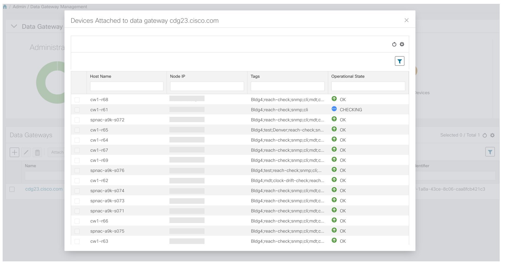
Note |
After attaching the devices to a Cisco Crosswork Data Gateway instance, the devices will be automatically synced with Cisco NSO. After you verify that the devices are in Cisco NSO, you must run the following commands from Cisco NSO:
|
Auto-Sync of Managed Devices With Cisco NSO
New devices that are added to Cisco Crosswork Network Controller are reflected automatically in Cisco NSO. Additionally, whenever device, credential, or provider data is changed, a sync operation will take place and the changes will reflect in Cisco NSO.
Note |
The device sync is one-directional - from Cisco Crosswork Network Controller to Cisco NSO. Devices cannot be imported or synced from Cisco NSO to Cisco Crosswork Network Controller. |
For auto-sync to work, you need to do the following in NSO (ncs.conf file):
-
• In the SSL section, enable HTTPS and specify port 8888.
-
• For an IPv6 NSO deployment, include the following in the SSL section:
<extra-listen>
    <ip>::</ip>
    <port>8888</port>
</extra-listen>
-
Netconf connectivity is configured for NSO as a provider and that the NSO provider is "Reachable". Go to .
-
Devices have a specified Software Type. Go to .
-
Devices are associated with credential profiles that contain an SSH entry. Go to .
Note |
After the devices have been synced with Cisco NSO, you must run the following commands from Cisco NSO:
|
Enable MDT Functionality on Devices
Cisco Crosswork Network Controller supports data collection from network devices using Model-driven Telemetry (MDT) to consume telemetry streams directly from devices.
MDT must be enabled after the devices have been onboarded and attached to a Cisco Crosswork Data Gateway instance. Follow these steps to enable MDT on managed devices:
Before you begin
-
Make sure that a Cisco NSO provider has been configured and is reachable. See Add Cisco NSO Providers.
Procedure
| Step 1 |
Add devices to the inventory:
|
| Step 2 |
When the devices have been added to the inventory, attach them to a Cisco Crosswork Data Gateway instance. See Attach a Device to a Cisco Crosswork Data Gateway Instance. At this stage, the devices will be automatically synced with Cisco NSO. See Auto-Sync of Managed Devices With Cisco NSO. |
| Step 3 |
Check that the devices have been pushed to Cisco NSO. |
| Step 4 |
In Cisco NSO, run the sync-from and fetch-host-keys commands for all the devices. |
| Step 5 |
Export all the devices that will have MDT capability to a .csv file:
|
| Step 6 |
In the .csv file, update the capabilities to include YANG_MDT and save the file. |
| Step 7 |
Import the updated .csv file into Cisco Crosswork Network Controller. See Import Devices. On successful import of the .csv file, the MDT configuration will be pushed to all the devices. |
Set Up Your Maps
The network topology can be displayed on a logical map or a geographical map, where the devices and links are shown in their geographic context. The logical map shows devices and their links, positioned according to an automatic layout algorithm, ignoring their geographical location. The geographical map shows single devices, device clusters, links, and tunnels, superimposed on a map of the world. Each device location on the map reflects the device's GPS coordinates (longitude and latitude).
To set up your maps and adjust them for your needs, see the following sections:
Choose a Provider for the Geographical Map Display
-
The default map provider (Mapbox)
-
A map provider of your choice
-
Locally installed map resources
The system is set up by default to get the geo map tiles from a specific Mapbox URL through a direct Internet connection. If required, you can use a different (custom) map tiles provider by providing a specific URL. Both of these options require an Internet connection. If you do not have an Internet connection, you can install the map resources locally and specify that you want the system to use the local map resources, which means that you are effectively working offline. See Use Internal Maps for Geo Map Display for more information.
To choose a geo map provider:
Procedure
| Step 1 |
From the main menu, choose and click the Map tab.
|
| Step 2 |
Click Save. |
Use Internal Maps for Geo Map Display
Note |
If you choose to work offline with internal maps and you do not install map files, your geo map will display as a generic world map without details of cities, streets, and so on. |
To use internal maps for your geo map:
Before you begin
Download the required map files from Cisco.com and place them on an accessible server.
Procedure
| Step 1 |
From the main menu, choose and click the Map tab. |
| Step 2 |
Select the Work offline with internal maps radio button and click Manage. |
| Step 3 |
In the Manage Internal Maps dialog, Click |
| Step 4 |
In the Install New Map dialog, provide details of the server to which you downloaded the map file so that the system can access the file. Note that this server must support SCP protocol for file transfer. |
| Step 5 |
Click Install Map. The system uploads the map from the specified server. When the process is complete, the new map appears under Installed Maps in the Manage Internal Maps dialog.
|
| Step 6 |
Install additional maps, as required. |
| Step 7 |
Click Update All Maps to save all changes to installed maps. This update process might take some time. |
Set Display Preferences for Devices and Links
You can determine how devices and links will be shown on the topology map, based on your needs and preferences.
To set map display preferences, click ![]() in the top right section of the topology map.
in the top right section of the topology map.
-
For devices, you can choose whether to show the device state and how the devices should be labeled. By default, the device state is shown on the map and the host name is used to label devices.
-
For links, you can choose whether to show aggregated links and how links should be colored so that you can easily see their state and utilization status. By default, aggregated links will be differentiated from single links on the map and links will be colored based on link utilization thresholds. Administrators can change the utilization thresholds and their corresponding colors. See Define Color Thresholds for Link Bandwidth Utilization.
Define Color Thresholds for Link Bandwidth Utilization
Cisco Crosswork Network Controller comes with a default set of bandwidth utilization thresholds (percentage ranges) and corresponding color indicators. You can customize these to meet your needs, taking into account the following notes and limitations:
-
You can enter values in the "To" ranges. Each row begins automatically from the end of the previous row's range.
-
The thresholds must be sequential, meaning that each row's range must follow on from the previous row's range. For example, if the range in the first row is 0-25%, the second row's range must end with a value greater than 25.
-
You cannot use the same color for multiple thresholds. For example, you cannot choose Green for both the first and second rows.
Administrator privileges are required to change these settings.
Procedure
| Step 1 |
From the main menu, choose . |
| Step 2 |
Click the Bandwidth Utilization tab. |
| Step 3 |
In the Polling Interval field, enter a whole number from 5 to 60 (minutes) to specify how often links will be polled for bandwidth utilization. By default, link bandwidth is polled every 5 minutes. |
| Step 4 |
In the Link Coloring Thresholds area, define the criteria for coloring the links. Each row defines a color and the bandwidth percentage range that the color will represent. The default thresholds are:
|
| Step 5 |
Click Save. |
Set Up Bandwidth on Demand and Bandwidth Optimization
During installation of Cisco Crosswork Network Controller, the following function packs are installed:
-
Bandwidth on Demand (BoD): This function pack provides a bandwidth-aware Path Computation Element (PCE) to derive SR policy paths with requested bandwidth when available. Computed paths are deployed to the network through SR-PCE. BWoD continuously monitors link utilization to ensure no congestion occurs along the path. If conditions change in the network which causes link utilization to exceed the congestion threshold set by the user, BWoD automatically reoptimizes the policy path. See Bandwidth on Demand and Configure Bandwidth on Demand.
-
Bandwidth Optimization (BWOpt): This function pack provides automated SR policy based tactical traffic engineering capability to detect and mitigate congestion in your network. It achieves this through a real-time view of the network topology overlaid with a demand matrix built through telemetry-based Segment Routing Traffic Matrix (SRTM). BWOpt uses the threshold interface utilization requested by the user and compares it to the actual utilization in the network. When interface congestion is detected by BWOpt, it attempts to shift traffic away from hot spots through the use of tactical traffic engineered SR policies which are deployed to the network via SR-PCE. As network conditions (topology and/or traffic) change over time, BWOpt will continue to monitor interface utilization and manage any tactical SR policies deployed, including changing their paths and/or removing them from the network when deemed no longer necessary. See Bandwidth Optimization and Configure Bandwidth Optimization.
Bandwidth on Demand
The Bandwidth on Demand (BWoD) function pack provides a bandwidth-aware Path Computation Element (PCE) to derive SR policy paths with requested bandwidth when available. Computed paths are deployed to the network through SR-PCE. BWoD continuously monitors link utilization to ensure no congestion occurs along the path. If conditions change in the network which causes link utilization to exceed the congestion threshold set by the user, BWoD automatically reoptimizes the policy path.
BWoD utilizes a near real-time model of the network along with a demand matrix derived from telemetry-based Segment Routing Traffic Matrix (SRTM) reporting to ensure BWoD policies meet their bandwidth constraints. Users may fine tune the behavior of BWoD, affecting the path it computes, through the selection of application options including network utilization threshold (definition of congestion) and path optimization objectives. The BWoD function pack works as a bandwidth-aware PCE for SR policies created through the Cisco Crosswork Network Controller UI, and for SR policies created through CLI configuration on a headend with delegation to SR-PCE. In the latter case, SR-PCE will subdelegate the SR policy with bandwidth constraint to BWoD for path computation and relay the computed path returned by BWoD to the headend for instantiation.
Operation Modes
There are two modes of operation for BWoD based on the "Priority" option setting for the application. In non-Priority mode, BWoD takes into account all traffic in the network when computing a path for a SR policy with bandwidth constraint. In this case, BW SR policies compete with all other traffic for resources and may be provided a path that is longer to avoid congestion on links along the shortest path.
Note |
In non-Priority mode, BWoD should not be enabled at the same time as the Bandwidth Optimization function pack to ensure they do not conflict. |
The Priority mode allows BWoD to ignore all other traffic in the network that is not flowing through a BWoD SR policy and give its policies priority treatment when computing paths. This means that BWoD policies are only contending for resources with other BWoD policies and will likely take the shortest path unless there are links that include a significant amount of other BWoD traffic.
Note |
To mitigate any congestion that may occur by ignoring other traffic, the Bandwidth Optimization function pack should be used in conjunction with BWoD in the Priority mode to shift other traffic away from any hotspots caused by the BWoD traffic. |
The other traffic may then be sent over alternate (possibly longer) paths to mitigate congestion in this case, while BWoD maintains its policies along the shortest paths.
Configure Bandwidth on Demand
Do the following to enable and configure Bandwidth on Demand.
Procedure
| Step 1 |
From the main menu, choose . 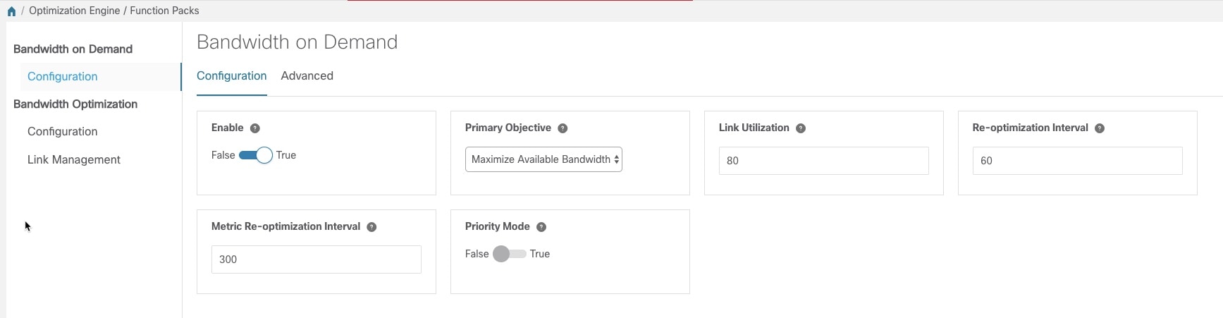 |
| Step 2 |
From the Enable tile, toggle the slider to True. Notice that each time a tile is updated it turns blue. |
| Step 3 |
Select one of the following Primary Objectives:
|
| Step 4 |
In the Link Utilization tile, enter the congestion constraint (in percentage). When the Bandwidth on Demand application searches a path for the policies being delegated, it will avoid any paths that may exceed the congestion utilization threshold. |
| Step 5 |
In the Reoptimization Interval tile, enter the duration (in seconds) after which the paths will be reoptimized if conditions in the network change. This is a count down timer where the BWoD policy will wait to reoptimize until this duration has expired. |
| Step 6 |
In the Metric Reoptimization Interval tile, enter the duration (in seconds) after which the paths can be reoptimized for metric optimization. If the bandwidth constraint is still being met, but a shorter IGP or TE path is available, BWoD will not run reoptimization until the timer has expired. This value is meant to dampen frequent path changes and reoptimizations in the network. |
| Step 7 |
From the Priority Mode tile, toggle the slider to True if you have also enabled Bandwidth Optimization. |
| Step 8 |
Click the Advanced tab for more advanced configuration (see the following table for field descriptions). |
| Step 9 |
Click Commit Changes to save the configuration. |
| Field | Description |
|---|---|
| Private New SR Policies |
If True, all policies that are created using Bandwidth on Demand are private. |
|
SR Policy Traffic |
Determines the type of bandwidth optimization that is performed with each policy.
|
|
Deployment Timeout |
The time (in seconds) to wait for a PCE dispatcher response. |
|
Update Throttle |
When enabled, this option throttles updates from Cisco Crosswork Network Controller and instructs BWoD to only accept 1 update per x seconds. Set it to 0 to disable the throttle. |
|
Debug Optimizer |
|
|
Debug Opt Max Plan Files |
The maximum number of debug plan files you would like to save. |
|
Debug Opt |
If True, debug log files will be saved. |
Bandwidth Optimization
The Bandwidth Optimization (BWOpt) function pack provides automated SR policy based tactical traffic engineering capability to detect and mitigate congestion in your network. It achieves this through a real-time view of the network topology overlaid with a demand matrix built through telemetry-based Segment Routing Traffic Matrix (SRTM). BWOpt uses the threshold interface utilization requested by the user and compares it to the actual utilization in the network. When interface congestion is detected by BWOpt, it attempts to shift traffic away from hot spots through the use of tactical traffic engineered SR policies which are deployed to the network via SR-PCE. As network conditions (topology and/or traffic) change over time, BWOpt will continue to monitor interface utilization and manage any tactical SR policies deployed, including changing their paths and/or removing them from the network when deemed no longer necessary.
Configure Bandwidth Optimization
After Bandwidth Optimization is enabled, Cisco Crosswork Network Controller monitors all interfaces in the network for congestion based on the configured utilization threshold. When the utilization threshold is exceeded, it automatically deploys tactical polices and moves traffic away from the congested links. When congestion is alleviated, Bandwidth Optimization automatically removes the tactical SR policy.
Do the following to enable and configure Bandwidth Optimization.
Procedure
| Step 1 |
From the main menu, choose . 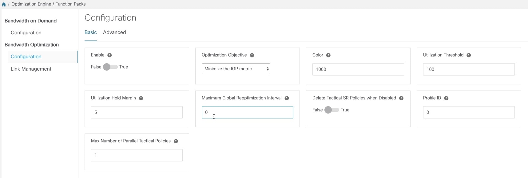 |
||
| Step 2 |
From the Enable tile, toggle the slider to True. Notice that each time a tile is updated it turns blue. |
||
| Step 3 |
Select one of the following Optimization Objectives:
|
||
| Step 4 |
In the Color tile, enter a color value to be assigned to Bandwidth Optimization SR policies. |
||
| Step 5 |
In the Utilization Threshold tile, enter a percentage that represents the interface utilization threshold for congestion. Traffic utilization on any interface exceeding this threshold will trigger Bandwidth Optimization to attempt to mitigate. To set thresholds for individual links, see Set Bandwidth Threshold for Links. |
||
| Step 6 |
In the Utilization Hold Margin tile, enter a percentage that represents the utilization below the threshold required of all interfaces to consider removing existing tactical SR policies. For example, if the Utilization Threshold is 90% and the Utilization Hold Margin is 5%, then tactical SR policies deployed by Bandwidth Optimization will only be removed from the network if all interface utilization is under 85% (90 - 5) without the tactical policy in the network. This serves as a dampening mechanism to prevent small oscillations in interface utilization from resulting in repeated deployment and deletion of tactical SR policies. The Utilization Hold Margin must be between 0 and the Utilization Threshold. |
||
| Step 7 |
In the Maximum Global Reoptimization Interval tile, enter the maximum time interval (in minutes) to reoptimize the existing tactical SR policies globally. During a global reoptimization, existing tactical policies may be rerouted or removed to produce a globally more optimal solution. Set to 0 to disable. |
||
| Step 8 |
From the Delete Tactical SR Policies when Disabled tile, toggle the slider to True if you want all deployed tactical SR policies deleted when Bandwidth Optimization is disabled. |
||
| Step 9 |
In the Profile ID tile, enter the profile ID that will be assigned to tactical SR policies that are created. Enter 0 if you do not wish to assign a profile ID. |
||
| Step 10 |
In the Max Number of Parallel Tactical Policies tile, enter the number of parallel tactical polices that Bandwidth Optimization can create between the same source and destination to obtain the utilization threshold. This is helpful when faced with large demands that cannot be moved in its entirety. Having the ability to create parallel tactical policies increases the chance for Bandwidth Optimization to mitigate congestion. |
||
| Step 11 |
Click the Advanced tab for more advanced configuration (see the following table for field descriptions). |
||
| Step 12 |
Click Commit Changes to save the configuration. Cisco Crosswork Network Controller begins to monitor network congestion based on the threshold that was configured.
|
| Field | Description |
|---|---|
| Fix Tactical SR Policy Duration |
The minimum time (in seconds) between the creation of a new tactical SR policy and when it can be removed or modified. This serves as a dampening factor to control the rate of change to deployed tactical SR policies. |
|
Removal Suspension Interval |
The time (in seconds) between any tactical SR policy change and when any tactical SR policy can be removed or modified. This allows SRTM to converge after a tactical SR policy creation, allowing traffic on the policy to be reported accurately. |
|
Deployment Timeout |
The maximum time (in seconds) to wait until deployment of tactical SR policies is confirmed. The value assigned should be larger for larger networks to account for the increased processing time needed by SR-PCE to deploy an SR policy. Tactical SR policies not confirmed before this timeout are declared failed and Bandwidth Optimization will disable itself for troubleshooting. |
|
Congestion Check Suspension Interval |
The minimum duration in seconds after any tactical SR policy addition or deletion to suspend congestion detection or mitigation to allow model convergence. |
|
Debug Optimizer |
|
|
Debug Opt Max Plan Files |
The maximum number of optimizer debug files written to disk. |
|
Debug Opt |
If True, optimizer debug files will be saved to disk in the /tmp directory of the Bandwidth Optimization container. |
Set Bandwidth Threshold for Links
Networks have many different links (10G, 40G, 100G) that require different thresholds to be set. The Bandwidth Optimization Link Management feature allows a threshold value to be set per interface instead of just one value for the entire network.
Procedure
| Step 1 |
From the main menu, choose . |
| Step 2 |
Click |
| Step 3 |
Click the Download sample configuration file link. |
| Step 4 |
Open and edit the file with the node, interface, and threshold information that you want to set. |
| Step 5 |
Save the file with your changes and go back to the Import Configuration File dialog box. |
| Step 6 |
Click Browse and navigate to the CSV file you just edited. |
| Step 7 |
Click Import. Bandwidth Optimization checks the CSV node entries for validity. If valid, all the entries appear in the Link Management table. |
| Step 8 |
You can do the following from this table:
|
Additional Useful Information
Although not strictly related to getting up and running, the following topics provide additional information that might be useful when working with Cisco Crosswork Network Controller.
Change the IP Address of the Cisco NSO Provider
To change the IP address of the Cisco NSO provider:
Before you begin
This task must be done during a maintenance window.
Procedure
| Step 1 |
Set all devices to ADMIN_DOWN state and remove YANG_MDT capability from devices, where relevant. This can be done in bulk by exporting the devices to a .csv file, making the change for all the devices in the .csv file, and then importing the file back into Cisco Crosswork Network Controller.
|
| Step 2 |
Import the updated .csv file. See Import Devices. |
| Step 3 |
Edit the provider:
Within a few minutes, all the devices should be synced to the updated Cisco NSO provider. |
| Step 4 |
Check that the devices have been pushed to Cisco NSO. |
| Step 5 |
In Cisco NSO, run the sync-from and fetch-host-keys commands for all the devices. |
| Step 6 |
Replace YANG_MDT capability on the relevant devices and set all the devices to ADMIN_UP state by exporting the devices to a .csv file, updating the file, and then importing it back into Cisco Crosswork Network Controller, as described above. |
| Step 7 |
Check that the MDT configuration has been added to the devices. |
Update Device Information
Device information can be updated for individual devices or for multiple devices at the same time (using the export and import functions).
Before you begin
You must change the device state to ADMIN_DOWN before updating any of the following device parameters:
-
Connectivity information
-
Capability
-
Telemetry information
Procedure
| Step 1 |
Before updating devices, it is always good practice to export a backup of the devices.
|
| Step 2 |
Make sure that the state of the devices you want to update is ADMIN_DOWN. |
| Step 3 |
From the main menu, choose . |
| Step 4 |
Select the device(s) you want to update, then click |
| Step 5 |
Edit the device parameters, as required. For a description of the fields you can update, see Add Devices Through the UI. |
| Step 6 |
Click Save. |
| Step 7 |
Confirm device reachability. |
Delete Devices
Complete the following procedure to delete devices.
Before you begin
-
If the auto-onboard managed or unmanaged options are set for the SR-PCE provider, you should set auto-onboard for the SR-PCE(s) to off.
-
Confirm that the device is not connected to the network or that it is powered off before deleting the device.
-
If a device has services associated with it, you must remove the service associations in Cisco NSO before deleting the device in Cisco Crosswork Network Controller. If the service removal is not fully successful, zombie links might remain in Cisco NSO. In this case, the device would be deleted successfully in Cisco Crosswork Network Controller but you need to remove the zombie links and delete the device from Cisco NSO.
Note |
|
Procedure
| Step 1 |
Export a backup CSV file containing the devices you plan to delete. |
| Step 2 |
From the main menu, choose . |
| Step 3 |
(Optional) In the Devices window, filter the list of devices by entering text in the Search field or filtering specific columns. |
| Step 4 |
Check the check boxes for the devices you want to delete. |
| Step 5 |
Click If you want to delete devices in bulk, Cisco recommends that you change the device state in this manner in batches of 50 devices, then complete deletion of these devices before deleting another batch. |
| Step 6 |
Click |
| Step 7 |
In the confirmation dialog box, click Delete. |
 Feedback