Cisco Service Control Product Installation Guide
Available Languages
Table Of Contents
Cisco Service Control Product Installation Guide
Cisco Service Control Topology
Cisco SCE8000 Platform Topologies
Dual Cisco SCE8000 Topology (Cascade)
Multi-Gigabit Service Control Platform (MGSCP) Topology
Installing the SCE8000 Platform
Installing the Subscriber Manager
Installing the Collection Manager
Ports Used by the Collection Manager Software
Installing the Sybase Database
Installing Collection Manager Software
Installing the SCA BB Application
How to Verify that the SCE Platform is Running a Compatible Version of the OS
How to Verify that the SM is Running a Compatible Version
How to Install the SCA BB Console
Installing the Application and Protocol Pack on the SCE Platform
How to Install Files on the SCE Platform
Initial Configuration of the Cisco SCE8000 Platform
How to Use the Usage Analysis Wizard to Define the Default Site
Configuring the Subscriber Manager
Cisco SCE 2000 Platform Installation
Cisco SCE 2000 Platform Topologies
Installing a Cisco SCE 2000 Platform
Multi-Gigabit Service Control Platforms (MGSCP) Topologies
System Requirements and Prerequisites
Obtaining Documentation and Submitting a Service Request
Cisco Service Control Solution Guide
Cisco Service Control Product Installation Guide
Revised: January 25, 2011, OL-18872-011 Overview
This overview introduces the components of the Cisco Service Control solution and gives a high-level explanation of the total installation process.
System Components
The Cisco Service Control solution consists of five main components:
•
The Service Control Engine (SCE) platform: A flexible and powerful dedicated network-usage monitor that is purpose-built to analyze and report on network transactions at the application level.
For complete information regarding the installation and initial configuration of the SCE platform, see the Cisco SCE Platform Installation and Configuration Guides.
•
For complete information regarding the installation and operation of SCA BB, see the Cisco Service Control Application for Broadband (SCA BB) User Guide.
•
For complete information regarding the installation and operation of the SM, see the Cisco Service Control Management Suite Subscriber Manager User Guide.
The Quota Manager (QM) is an optional component of the Subscriber Manager. It enables Service Control solution providers to manage subscriber quota across subscriber sessions with a high degree of flexibility.
For complete information regarding the installation and operation of the QM, see the Cisco Service Control Management Suite Quota Manager Solution Guide.
The Virtual Link Manager (VLM) is a component of the Subscriber Manager that enables Service Control solution providers to monitor and control individual subscriber links separately by creating a single policy that contains the tier differentiated packages, creating a number of virtual links and then assigning subscribers to the virtual links. For full details, see the Cisco Service Control for Managing Remote Cable MSO Links Solution Guide.
•
For complete information regarding the installation and operation of the CM, see the Cisco Service Control Management Suite Collection Manager User Guide.
•
For complete information regarding the installation and operation of the Reporter, see the Cisco SCA BB Reporter User Guide.
Together, the SCE platform, the SCMS-CM, the SCMS-SM, and the SCA Reporter are designed to support detailed classification, analysis, reporting, and control of IP network traffic. The SCMS-CM, the SCA Reporter, and the SCMS-SM are optional components; not all deployments of the Cisco Service Control solution require them. Sites that employ third-party collection and reporting applications, those that do not require dynamic subscriber-aware processing, and those that use a Radius or DHCP sniffing option may not require all of these components.
Options and Versions
The Cisco SCE Platform
The Cisco SCE platform is available in three versions:
•
•
•
All platform versions are available with either AC or DC power.

Note
The SCA BB Application
SCA BB is not available in different versions.
Subscriber Manager (SM)
The SM is available in the following versions:
•
•
Both SM versions are available with the following options:
•
•
Collection Manager (CM)
The CM is available in the following versions:
•
•
Both CM versions are available with either of the following options:
•
•
Reporter
The Reporter does not come in different versions.
System Installation Overview
The following figure shows the order of installing the components of the Cisco Service Control system
Figure 1 Installing the Complete Cisco Service Control Product

To install the complete Cisco Service Control system, complete the following steps:
Step 1
This includes:
•
•
•
Step 2
This includes:
•
•
•
Step 3
This includes:
•
•
•
•
•
Step 4
Step 5
Step 6
Step 7
2 Cisco Service Control Topology
This chapter describes the possible deployment topologies of the Cisco Service Control Solution.
Note
Overall System Topology
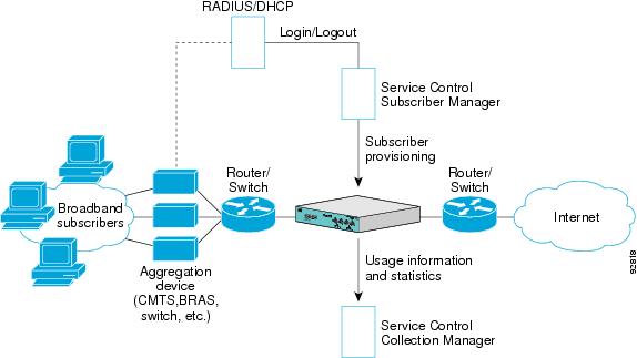
Figure 2 illustrates the general topology of the Cisco Service Control solution.
•
The SCE platform monitors traffic flow.
•
The SM provides subscriber data. This allows SCA BB to conduct subscriber-level analysis and control.
Figure 2 Flow of Information in SCA BB
Cisco SCE8000 Platform Topologies
The Cisco SCE8000 is a solution for dual links with load sharing and asymmetrical routing and support for fail-over between two SCE platforms.
The Cisco SCE8000 is built to support wire speed processing of full-duplex 10GBE streams. The Cisco SCE8000 can, therefore, be deployed in a multi-link environment, in several different topologies.
•
•
•
Physical Topologies
Following are descriptions of a number of physical topologies that the Cisco SCE8000 supports.
•
•
•
•
Single Cisco SCE8000 Topologies
A single Cisco SCE8000 supports both single 10GBE link and dual 10GBE link topologies.
•
•
•
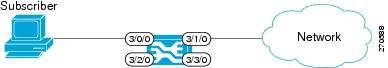
Single Link: Inline Topology
Typically, the Cisco SCE8000 is connected in a full duplex 10GBE link between two devices (Router, BRAS, etc.). When the Cisco SCE8000 is installed as an inline installation, it physically resides on the data link between the subscribers and the network.
Figure 3 Single Link: Inline Topology
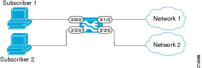
Dual link: Inline Installation
In this topology, one Cisco SCE8000 is connected inline in two full duplex, 10GBE links.
In case the two links are load-shared, asymmetrical routing might occur, and some of the flows may be split, that is, the upstream packets of the flow go on one link, and the downstream packets go on the other link.
When installed in this topology, the Cisco SCE8000 completely overcomes this phenomenon, and provides its normal functionality as if asymmetrical routing were not occurring in the two links.
Figure 4 Dual link: Inline Installation
Single Link: Receive-only Topology
In this topology, an optical splitter resides physically on the 10GBE link between the subscribers and the network. The traffic passes through the optical splitter, which splits traffic to the Cisco SCE8000. The Cisco SCE8000, therefore, only receives traffic and does not transmit.
Figure 5 Single Link: Receive-only Topology
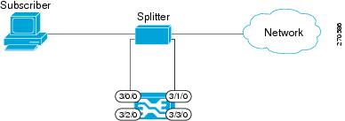
In an optical splitter topology, the Cisco SCE8000 only enables traffic monitoring functionality.
Note
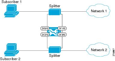
Dual Link: Receive-Only Topology
In this topology, one Cisco SCE8000 is connected in receive-only mode to two full duplex, 10 GBE links using optical splitters.
As with the dual link, inline topology, this topology completely overcomes the problem of asymmetrical routing.
Figure 6 Dual Link: Receive-Only Topology
Note
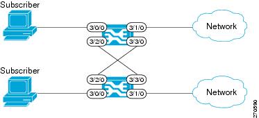
Dual Cisco SCE8000 Topology (Cascade)
In this topology, two cascaded Cisco SCE8000s are used. This allows a fail-over solution, where in case of a failure of one Cisco SCE8000 the functionality that the Cisco SCE8000 provides is preserved by the redundant platform.
This topology allows both control and monitoring functionality where redundancy is required and "inline" connection is used. The two Cisco SCE8000s are cascaded, so the primary Cisco SCE8000 processes the traffic of the two links, while the secondary Cisco SCE8000 only bypasses the traffic of its links to the primary Cisco SCE8000 for processing, and then bypasses the processed traffic back to the link. The two Cisco SCE8000s also exchange keep-alive messages and subscriber state information.
In case the primary Cisco SCE8000 fails, the two Cisco SCE8000s switch their roles, and this way fail-over is provided.
Figure 7 Two Cascaded Cisco SCE8000 Platforms
This fail-over solution preserves the Cisco SCE8000 functionality and the network link:
•
•
•
•
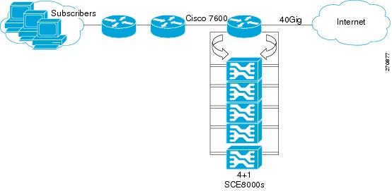
Multi-Gigabit Service Control Platform (MGSCP) Topology
In this topology, multiple Cisco SCE8000 platforms are connected to a Cisco 7600 Series router, which acts as a dispatcher between the platforms. The router contains two EtherChannels (ECs), one for the subscriber side and one for the network side, that perform load balancing for the SCE platform traffic. Traffic enters the first router, is distributed between the SCE platforms by the subscriber-side EC and then returns to the router so it can be forwarded to its original destination.
Figure 8 Basic MGSCP Topology
There are a number of variables to be considered in the MGSCP topology. Two of the main factors to be considered include:
•
•
Type of SCE Platform Redundancy
•
All ports in the EC and all SCE platforms are active. If there is a failure in one of the SCE platforms, the links on the related ports in the EC will be down and the EC will automatically exclude it from the load distribution. The load will then be distributed between the remaining active SCE platforms.
Since the Cisco SCE8000 supports two links, this configuration requires one SCE platform per two links (two EC ports).
•
'N' SCE platforms are active and one platform is on standby. The EC ports connected to the standby SCE platform must be configured as standby ports. In the case of failure of one of the SCE platforms, the EC ports connected to the failing SCE platform are shut and the standby EC ports, connected to the standby SCE platform, will be activated.
Since the Cisco SCE8000 supports two links, this configuration requires one SCE platform per two links (two EC ports), plus one extra SCE platform for standby.
Note that the standby SCE platform must be connected to the two highest-numbered ports, since EC behavior automatically designates these as the standby ports.
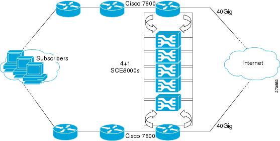
Redundant Cisco 7600 Series Router
Two Cisco 7600 Series routers can be used to provide network redundancy.
In this topology, one link on each Cisco SCE8000 platform is connected to each router. Therefore, one SCE platform is required for each link.
Figure 9 MGSCP with Redundant Router
3 System Installation
Installing the SCE8000 Platform
To install a Cisco SCE8000 platform, complete the following steps. (For more information, refer to the Cisco SCE8000 Installation and Configuration Guide.)
Note
Step 1
Step 2
Step 3
Step 4
Step 5
SCE8000 Connectivity
The following tables summarize SCE8000 connectivity for the basic topologies.
Receive-only topologies use only Receive fibers.
Note
Table 1 Single link inline connectivity
Table 2 Dual link inline connectivity
3/0/0
Link 0
Subscribers
3/1/0
Link 0
Network
3/2/0
Link 10
Subscribers
3/3/0
Link 1
Network
Table 3 Cascade connectivity
Table 4
Optical Bypass connectivity: Single link
Table 5
Optical Bypass connectivity: Dual link
Multi-Gigabit Service Control Platforms (MGSCP) Topologies
In an MGSCP deployment, the exact cabling scheme depends on the number and arrangement of ports in the EtherChannel in the Cisco 7600 Series router. It is therefore not possible to give exact cabling schemes. Refer to the following general guidelines when designing the cabling scheme.
General guidelines for MGSCP topologies:
•
•
•
•
•
–
–
When cabling to the EC, follow these guidelines:
•
•
•
Installing the Subscriber Manager
This section describes how to install SM Version 3.5.0 or later on a computer running Solaris or Red Hat Linux.
For more information, refer to the Cisco SCMS Subscriber Manager User Guide.
Step 1
Step 2
Set the system memory configuration requirements according to the maximum number of subscribers. See the Cisco Service Control Management Suite Subscriber Manager User Guide, the Installation and Upgrading chapter, the "Installation Procedure" section.
Step 3
TimesTen requires that certain changes be made in the operating system kernel configuration file:
•
•
These changes increase the shared memory and semaphore resources on the machine from their defaults. See the Cisco Service Control Management Suite Subscriber Manager User Guide, the Installation and Upgrading chapter, the "Installation Procedure" section.
Step 4
Note
The install-def.cfg file contains several parameters that can be preconfigured before installation of the SM. These parameters are copied by the install routine to the relevant SM configuration files. By default, all of the parameters are commented out and the default values are used.
The file contains the following parameters:
Step 5
Note
Note
From your workstation shell prompt, move to the directory to where the distribution file was extracted and run the install-sm.sh script. See the Cisco Service Control Management Suite Subscriber Manager User Guide, the Installation and Upgrading chapter, the "Installation Procedure" section.
Step 6
After the installation script has completed successfully, set the password for the pcube user by running the # passwd pcube command.
Note
Step 7
It is necessary to reboot the computer to complete the installation.
Step 8
It is necessary to add a user for PRPC authentication because SCA BB requires a username and password when connecting to the SM.
To add a user for PRPC authentication, use the p3rpc command-line utility. For example:
>p3rpc --set-user --username=pcube --password=pcube-password
Installing the Collection Manager
This section describes how to install the Collection Manager, either with the bundled Sybase database or unbundled, on a computer running Solaris or Red Hat Linux.
•
•
•
For more information, refer to the Cisco SCMS Collection Manager User Guide.
Ports Used by the Collection Manager Software
Table 6 describes the TCP/UDP ports on which the CM software and associated components (such as the Sybase database) listen. This table may help the network administrator understand the behavior of the software and its adherence to the security policy.
The ports listed are those on which the device listens constantly. You should allow access on these port numbers; otherwise, certain operations may fail.
Some operations (such as file transfer) cause a device to temporarily open ports other than those listed; however, these ports close automatically when the operation ends.
Installing the Sybase Database
If you do not want to install Sybase (for example, when working in unbundled mode), go to Installing Collection Manager Software.
Note
Note
Note
The installsyb.sh script installs the Sybase database. For information about actions performed by the script, see the Cisco SCMS Collection Manager User Guide.
Step 1
Step 2
Step 3
installsyb.sh --sybhome=SYBHOME {--datadir=DATADIR}•
•
–
Use a location in a partition where at least 15 GB is free.
•
Step 4
Use the passwd command as follows:
# passwd sybase
Installing Collection Manager Software
Use the install-cm.sh script to install the collection manager server.
install-cm.sh Options
The usage message for the install-cm.sh script is:
Usage: install-cm.sh [-h] (-d CMDIR | -o)Options: -d CMDIR select directory for ~scmscm(must not exist and must be on 8 GB free partition)-o upgrade the existing installationwhile preserving the current configuration(can't be used with -d)-h print this help and exitDescription of the options:
-d CMDIRUsed to designate the directory of the newly createdscmscm user's home. Should be the name of anon-existing directory, whose parent resides on apartition where at least 8 GB is free.As an alternate to this option, you can specify -o :-oUse this option when you wish to upgrade the existinginstallation while preserving the current configuration.(can't be used with -d)For information about actions performed by the install-cm.sh script, see the Cisco SCMS Collection Manager User Guide.
Step 1
Step 2
# install-cm.sh -d <CM home dir>Step 3
Run the following command to set the password for the scmscm user:
passwd scmscmBe sure to record the password that you choose.
Step 4
The following is a list of supported external databases:
•
•
•
For further information see the Cisco Service Control Management Suite Collection Manager User Guide, the "Managing the Collection Manager" chapter, the "Configuring Databases" section.
Step 5
If you are using an external database, start it according to the instructions supplied by the database vendor.
If you are using the Sybase database:
a.
# ~scmscm/setup/sybase start
b.
# ~scmscm/setup/alive.sh
Make sure the output does not contain the phrase "Sybase not functioning".
Step 6
For details, see the Cisco SCMS Collection Manager User Guide, the "Configuring the CM" section.
Step 7
~scmscm/cm/bin/cm startStep 8
For example, if the SCE device is located in GMT+2, run the following command as the scmscm user:
$ ~scmscm/cm/bin/jselect-sce-tz.sh --offset=120Step 9
~scmscm/db_maint/create_periodic_del_procs.shFor details, see the Cisco SCMS Collection Manager User Guide, the "Managing the Periodic Deletion of Old Records" section.
Step 10
Run the following command:
$~scmscm/scripts/dbperiodic.py --loadThis loads the default data retention settings defined in ~scmscm/db_maint/dbperiodic.conf.
Step 11
It is necessary to add a user for PRPC authentication because SCA BB requires a username and password when connecting to the CM.
To add a user for PRPC authentication, use the p3rpc command-line utility. For example:
~scmscm/cm/bin/p3rpc --set-user --username=scmscm --password=scmscm-password
Installing the SCA BB Application
This section describes how to install SCA BB application.
For more information, refer to the Cisco Service Control Application for Broadband User Guide.
SUMMARY STEPS
Step 1
Step 2
Step 3
•
•
•
Step 4
How to Verify that the SCE Platform is Running a Compatible Version of the OS
Step 1
Step 2
The response shows the version of the OS running on the SCE platform.
How to Verify that the SM is Running a Compatible Version
Step 1
Step 2
Step 3
The response to this command displays the SM version.
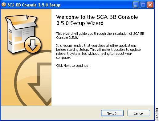
How to Install the SCA BB Console
Step 1
A standard installer wizard appears.
Step 2
How to Install the SCA BB Configuration Utilities
This step is optional.
Step 1
Step 2
The SCA BB Service Configuration Utility (servconf), the SCA BB Real-Time Monitoring Configuration Utility (rtmcmd) (and associated real-time monitoring report templates), and the SCA BB Signature Configuration Utility (sigconf) are located under the bin folder.
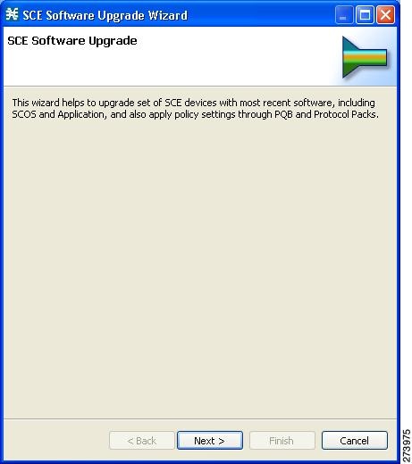
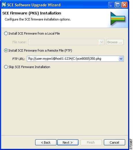
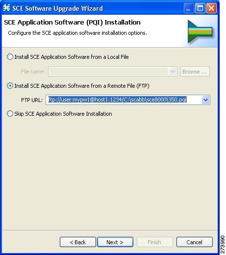
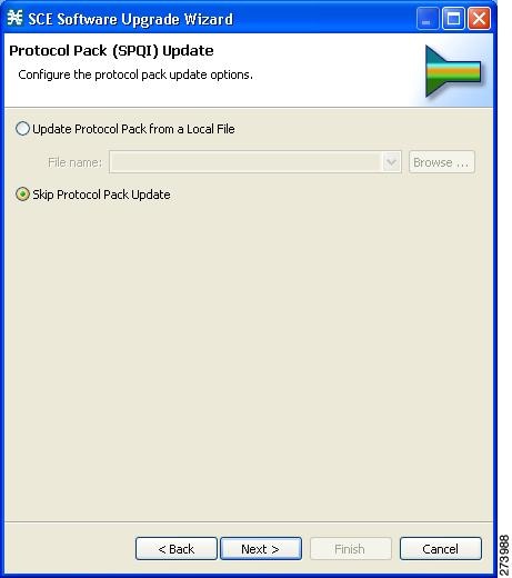
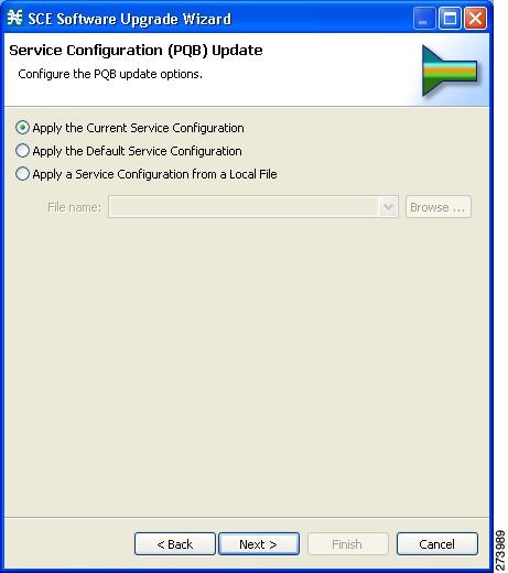
Installing the Application and Protocol Pack on the SCE Platform
Use the SCE Software Upgrade Wizard in the console to install the application file (pqi) and the protocol pack (spqi) on selected SCE platforms.
Before You Start
Before you begin the SCE platform upgrade, make sure you do the following:
•
•
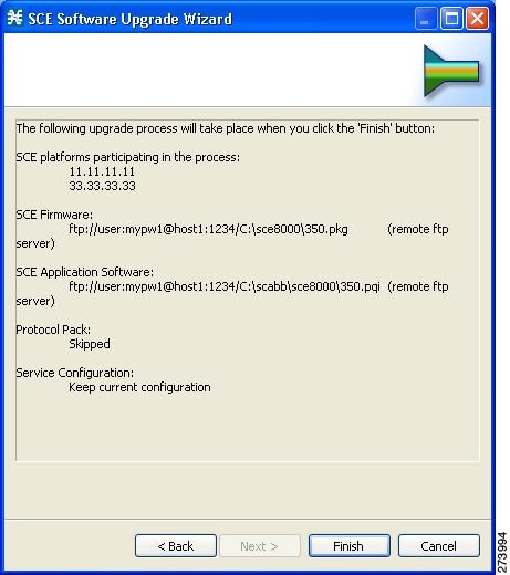
How to Install Files on the SCE Platform
Step 1
If the SCE platforms are not yet defined in the Network Navigator, you can select the site node.
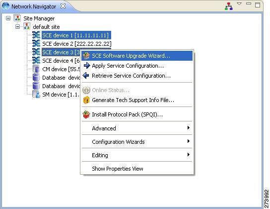
The SCE Software Upgrade Wizard opens.
Step 2
Step 3
Step 4
Step 5
Step 6
Step 7
Note
Step 8
Step 9
•
•
4 Initial Configuration
After all the Service Control components have been installed, perform the following tasks to complete the initial setup and configuration of the system:
Step 1
•
•
•
•
Step 2
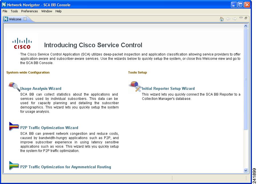
From the Network Navigator, run either the Usage Analysis Wizard, the P2P Traffic Optimization Wizard, or the P2P Traffic Optimization for Asymmetrical Routing Wizard.
Step 3
Step 4
Step 5
Note
Initial Configuration of the Cisco SCE8000 Platform
Note
There are several basic global parameters that must be correctly configured in order for the SCE platform to communicate properly with the outside world. The following is a very brief summary of the initial setup parameters and commands. For more information, refer to the Cisco SCE8000 Software Configuration Guide.
•
•
•
–
–
•
Passwords must meet the following criteria:
–
–
–
–
•
•
•
•
You must also enable DNS lookup.
•
The following table lists commands both for displaying the currently configured values and for configuring these parameters. It also lists the command mode for each configuration command. All show commands are executed from the User Exec command mode.
.
Initial SCA BB Configuration
Initial SCA BB configuration includes two main aspects:
•
•
Usage Analysis Wizard
This wizard does the following:
•
•
–
–
•
–
–
–
–
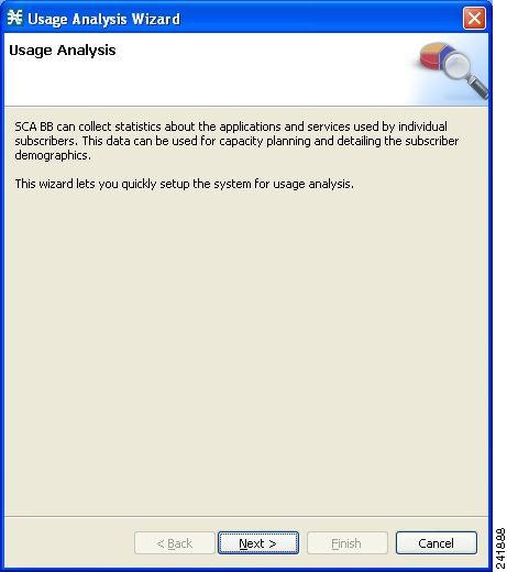
How to Use the Usage Analysis Wizard to Define the Default Site
The Usage Analysis wizard allows you to create a simple model of devices and connect to them.
Note
Step 1
The Welcome view opens.
Step 2
The Welcome page appears.
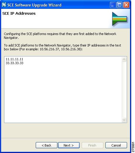
Step 3
The SCE IP Addresses page opens.
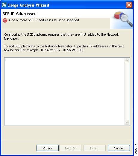
Step 4
Note
Step 5
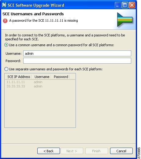
The SCE Usernames and Passwords page opens.
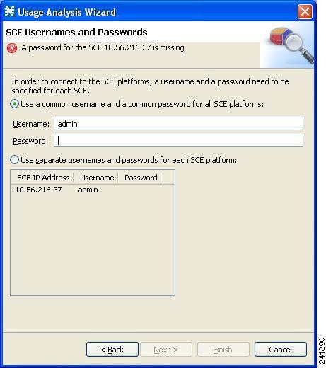
Step 6
Do one of the following:
•
•
Step 7
The CM Setup page opens.
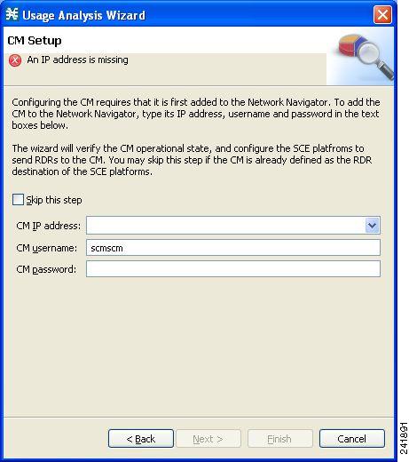
Step 8
Do one of the following:
•
If you started from the Network Navigator, this information is retrieved and displayed. You can modify these parameters.
•
Step 9
The Reporter Setup page opens.
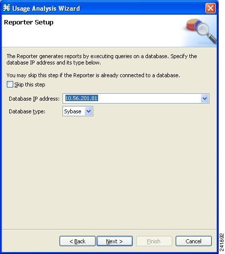
Step 10
Do one of the following:
•
If you started from the Network Navigator, this information is retrieved and displayed. You can modify these parameters.
•
Step 11
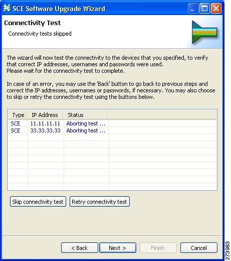
The Connectivity Test page opens.
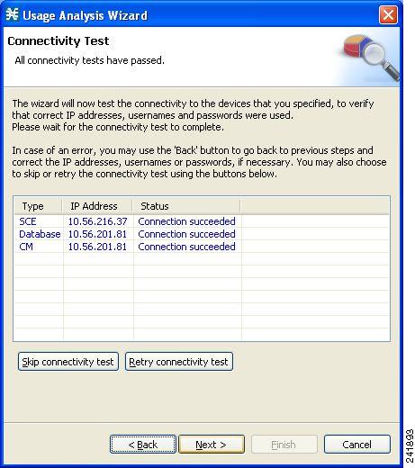
The wizard tests to see that the connections to the defined devices can be made.
Note
Step 12
The Anonymous Subscribers page opens.
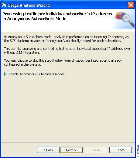
Step 13
Step 14
The Confirmation page opens.
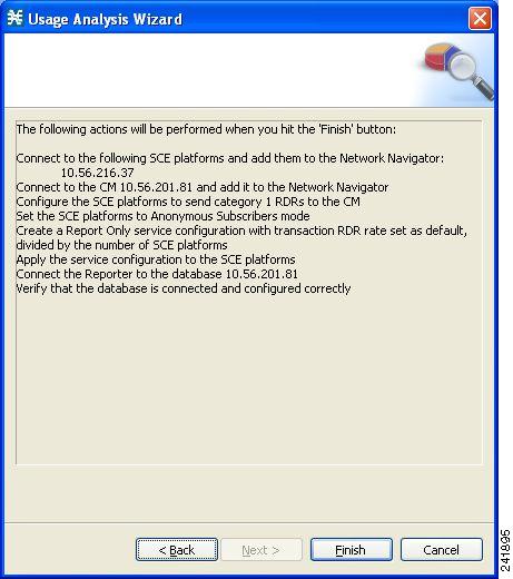
The actions that the wizard is about to take are listed in the page.
Step 15
The Configuration Output opens.
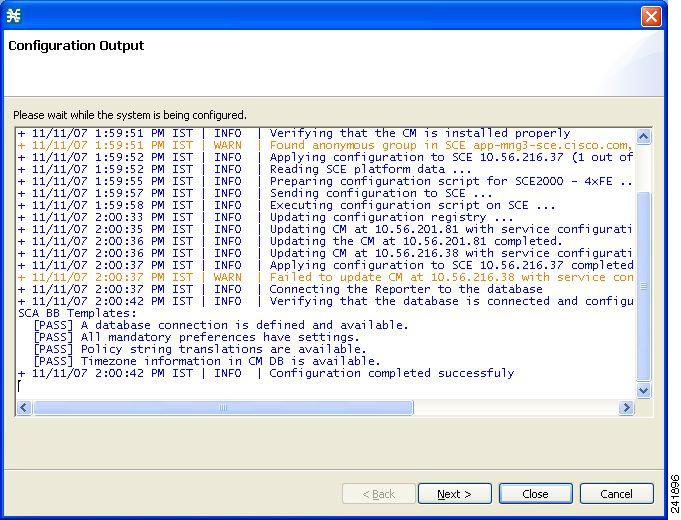
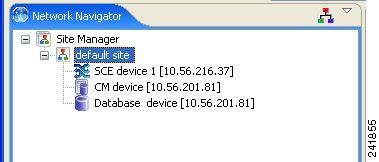
New devices are added to the default site of the Site Manager tree in the Network Navigator.
The wizard attempts to connect to all devices that you defined. The operation fails if:
–
–
–
If you defined a CM in Step 8, the SCE devices are configured so that the only category 1 RDR destination is the CM.
A new service configuration named Usage Analysis is created, and opens in the Service Configuration Editor.
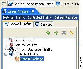
The service configuration has the following characteristics:
•
•
The service configuration is applied to the SCE devices.
If you defined a database in Step 10:
a.
b.
c.
Step 16
The Usage Analysis wizard closes.
Step 17
The Create common reports page opens.
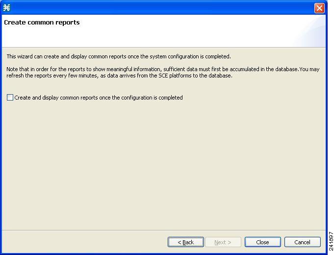
Step 18
Note
•
•
•
•
Step 19
The wizard closes.
The Reporter tool opens in the Console.
Report instances of each of the four report types open in the Report View of the Reporter tool.
Configuring the Subscriber Manager
After installing the SM, you can configure the SM to your specific needs. In particular, you should address the following parameters at this point:
•
•
•
To configure the SM, edit the p3sm.cfg configuration file using any standard text editor. The configuration file is described in detail in the Configuration and Management module and in the Configuration File Options module. After you finish editing the p3sm.cfg configuration file, use the p3sm utility to update the SM with the new settings:
Step 1
The following p3sm command loads the configuration file and updates the SM configuration accordingly.
>p3sm --load-config
5 Cisco SCE 2000 Platform Installation
This chapter summarizes the topologies and installation of the Cisco SCE 2000 platform. In general these are similar to the topologies and installation of the Cisco SCE8000 platform, but there are some differences.
Cisco SCE 2000 Platform Topologies
The Cisco SCE 2000 can be deployed in the same topologies as the Cisco SCE8000 platform. The following figures illustrate the Cisco SCE 2000 topologies.
Figure 10 Single SCE Platform Single Link: In-line Topology
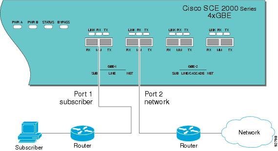
Figure 11 Single SCE Platform Dual Link Inline Topology
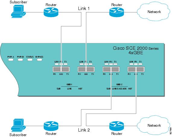
Figure 12 Single SCE Platform Single Link: Receive-Only Topology
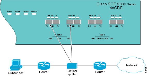
Figure 13 SCE Platform Dual Link Receive-Only Topology
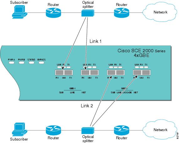
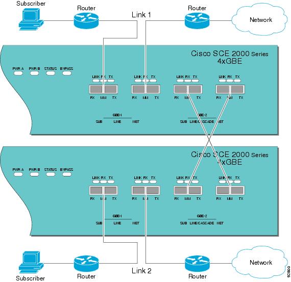
Figure 14 Two SCE Platforms: Dual Link Inline Topology
Installing a Cisco SCE 2000 Platform
To install the SCE platform, complete the following steps. (For more information, refer to the Cisco SCE2000 4xGBE Installation and Configuration Guide.)
Step 1
Step 2
Step 3
a.
--- System Configuration Dialog ---
At any point you may enter a question mark `?' followed by `Enter' for help.
Use ctrl-C to abort configuration dialog at any prompt.
Use ctrl-Z to jump to the end of the configuration dialog at any prompt.
Default settings are in square brackets `[]'.
Would you like to continue with the System Configuration Dialog? [yes/no]: y
b.
The system configuration dialog begins. See Initial System Configuration for information regarding the setup wizard.
Step 4
If using both MNG ports for redundancy, connect them to the LAN via a switch
Step 5
Initial System Configuration
Upon initial connection to the local terminal, as described above, the system configuration wizard automatically runs to guide the user through the entire setup process. The wizard prompts for all necessary parameters, displaying default values, where applicable. You may accept the default values or define other values.
With the exception of the time settings, which take effect immediately when entered, the new configuration is applied and saved only at the end of the dialog when approved by the user. Therefore, if the setup dialog is aborted, no change takes place in the configuration, other than time settings (if entered).
When the dialog is complete, you may review the new configuration before applying it. The system displays the configuration, including parameters that were not changed. The system also displays any errors that are detected in the configuration. When the configuration is satisfactory, you may apply and save the new configuration.
The following table lists all the parameters included in the initial configuration. It is recommended that you obtain values for any parameters that you will configure at this time before beginning the setup.
Note
Setup Command Parameters
SCE 2000 Connectivity
The following tables summarize SCE 2000 connectivity for the basic topologies.
Receive-only topologies use only Receive fibers.
Note
Table 9 Single link inline connectivity
Table 10 Dual link inline connectivity
0/1
Link 0
Subscribers
0/2
Link 0
Network
0/3
Link 10
Subscribers
0/4
Link 1
Network
Table 11 Cascade connectivity
Table 12
External Optical Bypass Module connectivity: Single link
Table 13
External Optical Bypass Module connectivity: Dual link
Multi-Gigabit Service Control Platforms (MGSCP) Topologies
In an MGSCP deployment, the exact cabling scheme depends on the number and arrangement of ports in the EtherChannel in the Cisco 7600 Series router. It is therefore not possible to give exact cabling schemes. Refer to the following general guidelines when designing the cabling scheme.
General guidelines for MGSCP topologies:
•
•
•
•
•
–
–
When cabling to the EC, follow these guidelines:
•
•
•
6 System Requirements and Prerequisites
Overall System Requirements
•
•
•
–
–
The actual number of computers required depends on the number of subscribers in the system.
•
–
–
The actual number of computers required depends on the amount of traffic in the system.
•
SCA BB System Requirements
•
Hardware Requirements
•
•
Operating System Requirements
•
Java Runtime Environment
If you are using the optional SCA BB Service Configuration Utility, servconf, it requires access to JRE version 1.6.
You can download a JRE from the Sun™ website at http://java.com/en/download/.
To verify that the JRE is installed, run java -version from the command prompt. The Java version should start with 1.6.
If a different version of JRE is also installed on the workstation, you may need to tell servconf where to find the appropriate JRE. Do this by setting the JAVA_HOME environment variable to point to the JRE 1.6 installation directory. For example:
JAVA_HOME=C:\Program Files\Java\j2re1.6_08SM System Requirements
You can install the SM on the following platforms:
•
•
The machine should conform to the system requirements listed in the following tables.
Note
For the hardware and software system requirements for the Veritas Cluster Server, see the Cisco Service Control Management Suite Subscriber Manager User Guide, the Veritas Cluster Server chapter.
Note
Note
Note
CM System Requirements
The CM and its database are software components that run on a server platform. They can be installed on any of the following configurations:
•
•
All configurations use a 32-bit Java virtual machine (JVM).

Caution
Note
•
Checking System Prerequisites
The CM distribution contains a script, check_prerequisites.sh, located in the install_scripts directory. The script helps to determine if a system meets the requirements for installing a CM or the bundled Sybase database.
The script checks overall readiness of the system for a CM or Sybase installation. The main prerequisites checked are:
•
•
•
•
•
•
•
•
•
check_prerequisites.sh [--sybhome=SYBHOME] [--cmhome=CMHOME] [--datadir=DATADIR]
Note
Solaris Requirements
Collection Manager Release 3.5.0 or later can be installed on any Sun SPARC Machine running Solaris that conforms to the requirements listed in the following sections.
•
Hardware
•
•
•
–
–
•
Software and Environment
•
•
•
•
•
system
SUNWadmap
System administration applications
system
SUNWadmc
System administration core libraries
•
•
•
The root (/) partition must have at least 104 MB of free space to install these packages.
•
–
–
–
•
•
•
•
•
•
•
•
forceload: sys/shmsys•
Setting the Locale and Time Zone
For correct CM and Sybase operation, U.S. English locale must be used. To set the locale, put the following line in the /etc/TIMEZONE configuration file (changes to this file require a restart to take effect):
LANG=en_USSolaris also needs to have this locale installed. Verify that the locale is installed by checking that the directory /usr/lib/locale/en_US exists. If the directory does not exist, install the locale files from the Solaris CDs.
Red Hat Linux Requirements
Collection Manager Version 3.5.0 or later can be installed on any i386 running Red Hat Linux that conforms to the requirements listed in the following sections.
•
Hardware
•
•
•
–
–
•
Software and Environment
•
–
–
–
•
–
–
–
•
•
•
•
•
•
•
•
•
•
Setting the Locale and Time Zone
•
7 Obtaining Documentation and Submitting a Service Request
For information on obtaining documentation, submitting a service request, and gathering additional information, see the monthly What's New in Cisco Product Documentation, which also lists all new and revised Cisco technical documentation, at:
http://www.cisco.com/en/US/docs/general/whatsnew/whatsnew.html
Subscribe to the What's New in Cisco Product Documentation as a Really Simple Syndication (RSS) feed and set content to be delivered directly to your desktop using a reader application. The RSS feeds are a free service and Cisco currently supports RSS Version 2.0.
Cisco and the Cisco Logo are trademarks of Cisco Systems, Inc. and/or its affiliates in the U.S. and other countries. A listing of Cisco's trademarks can be found at www.cisco.com/go/trademarks. Third party trademarks mentioned are the property of their respective owners. The use of the word partner does not imply a partnership relationship between Cisco and any other company. (1005R)
Any Internet Protocol (IP) addresses used in this document are not intended to be actual addresses. Any examples, command display output, and figures included in the document are shown for illustrative purposes only. Any use of actual IP addresses in illustrative content is unintentional and coincidental.
© 2011 Cisco Systems, Inc. All rights reserved.
 Feedback