Cisco Service Control for Managing Remote Cable MSO Links Solution Guide
Available Languages
Table Of Contents
Cisco Service Control for Managing Remote Cable MSO Links Solution Guide
Introduction and Solution Overview
Learning the Interface Topology
Learning the Interface Association
Managing Control and Reporting
Configuring Virtual Links Global Controllers
Applying Service Configurations to SCE Platforms
Configuring the Virtual Links Manager
Monitoring Using the p3vlink Utility
Monitoring Virtual Links Using the Reporter
Creating a New Report Instance
Verifying the Correct Policy is Enforced on a Specific Subscriber
Verifying that the Distribution of Subscribers to the Virtual Link is Correct
Inaccurate, Unavailable, or Missing Reports Information for a Specific CMTS Interface
Verifying that the VLM Updates the Collection Manager
SCE is Congested, But Connected CMTSs are Not Congested
Verifying that No Subscriber Is Associated with the Default Virtual Link
Obtaining Documentation and Submitting a Service Request
Cisco Service Control Solution Guide
Cisco Service Control for Managing Remote Cable MSO Links Solution Guide
Revised: January, 2009, OL-18380-011 About this Guide
This Cisco Service Control for Managing Remote Cable MSO Links Solution Guide describes the use of a Cisco Service Control solution in a cable environment to optimize traffic on remote links. It describes the setup of a solution that uses the Virtual Link Manager to enable traffic optimization of remote links, and the monitoring of that solution after deployment.
This guide assumes a basic familiarity with the concept of the Cisco Service Control solution, the Service Control Engine (SCE) platforms, and related components.
2 Introduction and Solution Overview
Introduction
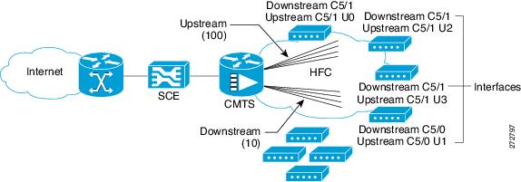
In Cable Multiple Service Operator (MSO) networks, the SCE is inserted in a location upstream of the Cable Modem Termination System (CMTS), which is the first IP hop in the MSO network. In this location, the SCE is often used to implement fair use policies (FUP) and perform congestion mitigation. MSOs work to ensure that the existing network infrastructure is used optimally using the SCE to enforce fairness between the different subscribers when the network is in the state of congestion.
The bandwidth of the radio frequency interfaces of the CMTS ranges from several megabits per second (Mbps) to tens of Mbps. The CMTS aggregates these interfaces into higher bandwidth upstream links, typically 1 gigabit per second (Gbps), where the SCE is connected.
Cable modems which are connected to the hybrid fiber coaxial cable (HFC) downstream connection of the CMTS are associated with CMTS interfaces. The CMTS interfaces can be termed upstream or downstream upon bootup or dynamically (depending on the direction of traffic flow) when you use some load balancing algorithms.
Figure 1 shows a typical deployment topology of an SCE in an MSO network.
Figure 1 SCE Deployed in MSO Network
Solution Overview
As part of this solution, the Virtual Link Manager (VLM) makes the SCE aware of the interface association of subscribers (cable modems) and accounts for and controls aggregate traffic in the context of a physical interface (CMTS upstream or downstream). This awareness allows the SCE to perform congestion mitigation at the level of the CMTS physical interface.
The solution is required to manage a large number of subscribers, each of which is connected to the CMTS and through it to the SCE. Within the CMTS, subscribers are connected to shared radio frequency interfaces, where they use the Data Over Cable Service Interface Specification (DOCSIS) MAC layer to transport their traffic. The shared radio frequency interfaces are termed upstream and downstream.
CMTS upstream and downstream interfaces are aggregated through the CMTS interface toward the core of the network, and eventually end in one or several physical interfaces that are connected to the SCE, which monitors and controls traffic.
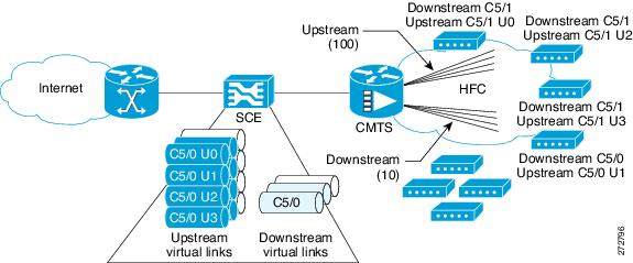
MSOs use the SCE to prioritize traffic within each of the CMTS radio frequency interfaces when traffic is congested. Cisco Service Control provides a virtual link concept that allows MSOs to monitor and control traffic for each interface.
Although it is possible to prioritize traffic by allocating packages to pairs of interfaces, this is time-consuming. The virtual links approach simplifies the model. Each virtual link is monitored and controlled separately within the service control solution, while virtual link provisioning is performed through the SCE CLI. The policy remains simple, and reflects only per subscriber tiering.
Figure 2 shows traffic traveling through the SCE that is mapped into SCE virtual links which reflect the CMTS physical interfaces. Monitoring and control is performed in the context of the virtual links.
Figure 2 Traffic Traversing SCE that is Mapped to SCE Virtual Links
The Cisco Service Control solution provides the VLM to automate many of the configuration actions that the network administrator ordinarily performs, including:
•
Provisioning virtual-link maps for each SCE based on the interface maps of the CMTSs that provide network access.
•
•
The virtual-link mapping configuration defines the mapping between:
–
–
Learning the Interface Topology
To control and report traffic in the context of a remote interface, you must map the topology in terms of the available CMTS interfaces and their associated bandwidth. This map must include keys that are used by the SCE to associate subscriber traffic with specific interfaces.
The SCE learns the interface topology by retrieving the CMTS configuration using the Simple Network Management Protocol (SNMP) and converting the configuration to a virtual links map. Virtual links are provisioned to the relevant SCEs.
Learning the Interface Association
Interface association awareness is achieved through DHCP integration. The CMTS IP (specifically, the Relay-Agent IP, or giaddr) is part of the DHCP dialog and upstream and downstream interface IDs are included in the Relay-Agent option (for example, option 82 [encoded in suboption 1, the circuit ID]). This information allows the SCE to uniquely identify upstream and downstream interfaces to which a subscriber is mapped, even in cases in which more than one CMTS is connected to an SCE.
The SCE DHCP sniffer login event generator (LEG) extracts the CMTS IP and reports it to the subscriber manager, which performs the appropriate virtual-link association, allowing the SCE to manage the traffic correctly.
Dynamic giaddr Learning
When the VLM queries the CMTS device, it reads all of the IP addresses from the CMTS device IP table and creates the mapping table that is used to map IPs to the CMTS device to which they are related. Many of the IP addresses that are read from the CMTS device are not used by subscribers which can cause the mapping table to become too big and unmanageable. To prevent this, the VLM dynamically learns and removes the giaddr values.
•
–
–
— The VLM adds this giaddr to be one of the CMTS device giaddr attributes.
— The VLM updates the DHCP LEG with the mapping table related to the new giaddr.
When the next DHCP transaction occurs, the subscriber is moved from the default vlink policy to a specific vlink policy.
•
–
–
–
–
The following example shows the current details of a subscriber:
p3subs --show -s lynn_jonesName: lynn_jonesDomain: subscribersMappings:IP: 1.1.1.13/32Properties:downVlinkId=7 Name=device1_1_Cmts8/1-downstream1upVlinkId=4 Name=device1_1_Cmts8/1-upstream1Custom Properties:giaddr=1.1.1.1Command terminated successfullyIf the IP address 1.1.1.1 is the removed giaddr and 2.2.2.2 is the CMTS device IP address, the result of the lease time operation is as follows:
p3subs --show -s lynn_jonesName: lynn_jonesDomain: subscribersMappings:IP: 1.1.1.13/32Properties:downVlinkId=7 Name=device1_1_Cmts8/1-downstream1upVlinkId=4 Name=device1_1_Cmts8/1-upstream1Custom Properties:giaddr=2.2.2.2Command terminated successfullyManaging Control and Reporting
SCE virtual links emulate the physical interfaces of the CMTSs and the VLM provisions the links with the bandwidth required to control the traffic.
1.
2.
3.
–
–
Subscriber management logic is required to associate subscribers with their upstream and downstream virtual links based on the attributes that the DHCP LEG extracts from the DHCP traffic.
In addition to the virtual links association, the subscriber is also assigned a package. In terms of bandwidth management, you can only use schemes that use one virtual-link-controller per direction; therefore, you should design the bandwidth controller architecture (committed information rate, peak information rate, and assurance level) accordingly.
3 Configuring the Solution
This chapter describes:
•
•
•
Solution Topology
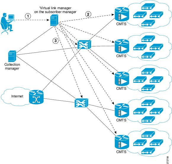
Figure 3 shows a system that can be configured for managing remote cable MSO links.
Figure 3 Traffic Optimization on Remote Links Topology

Note
To work with the collection manager, you must associate the collection manager with the SCE and also with the subscriber manager. However, it is not mandatory to associate the collection manager with the subscriber manager. In this case, the collection manager receives the RDRs but does not automatically receive the index to the vlink name mappings.
The operator configures the IP addresses of the CMTS devices, the SCEs, the CM, and their interrelations on the SM (1). The SM queries each CMTS device through SNMP to determine its interfaces and their corresponding interface speeds (2). The SM provisions the SCE virtual links (3).
CMTS Device Compatibility
This traffic optimization on remote links solution currently supports the following Cisco CMTS Universal Broadband Router (uBR) devices:
•
•
To use other CMTS devices, you must ensure the following conditions are met:
•
•
•
The traffic optimization on remote links solution uses the following MIBs and RFCs:
•
•
Prerequisites
Before you set up the managing remote cable MSO links solution, you must complete the following:
•
•
Configuring the Solution
The procedures in this section describe how to configure the solution.
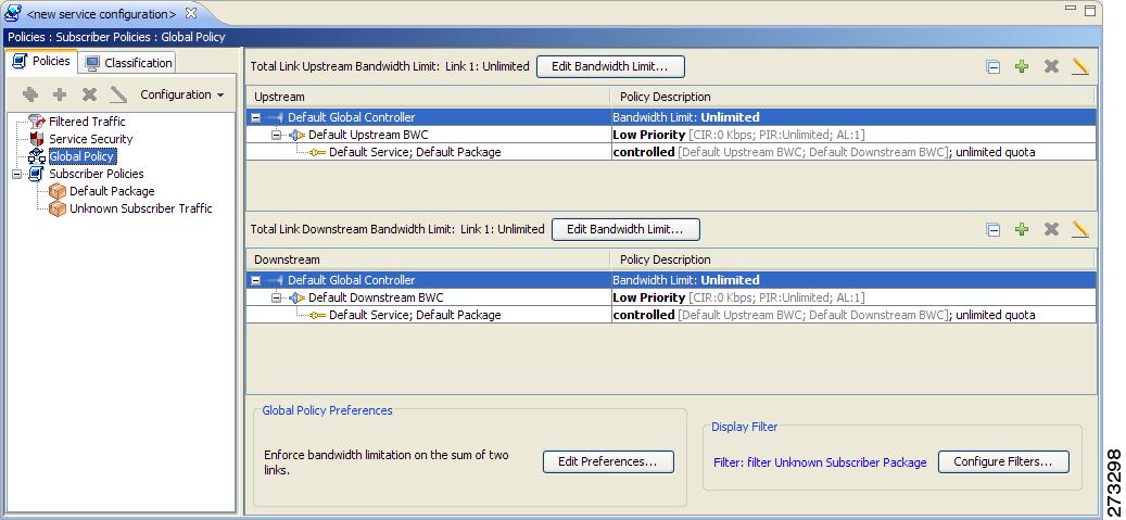
Configuring Virtual Links Global Controllers
Step 1
The Cisco Service Control SCA BB Console splash screen appears. After the Console loads, the main window of the Console appears. The first time that you launch the Console, the Welcome view is open in the main window.
Step 2
Step 3
If no service configurations are open when you open the Service Configuration Editor tool, a No Service Configuration Is Open dialog box appears.
a.
b.
c.
The new service configuration is added to the Console window, open on the Policies tab, and becomes the active service configuration.
Step 4
The Global Controllers mode dialog box appears.
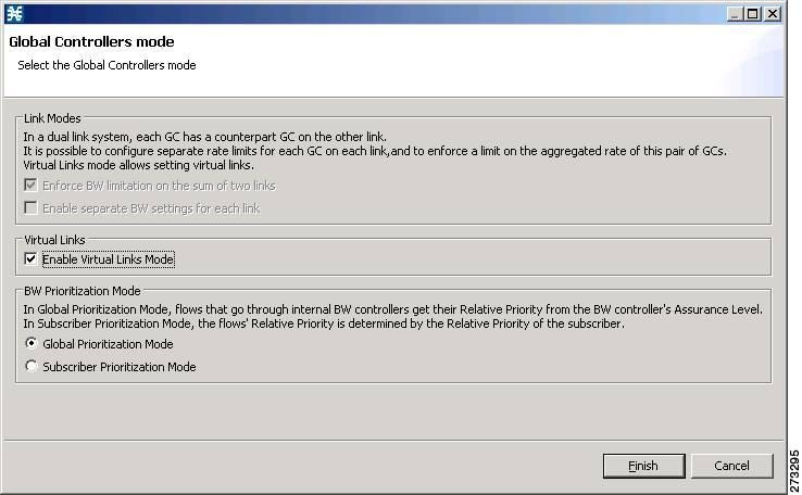
Step 5
Step 6
Applying Service Configurations to SCE Platforms
Step 1
Step 2
The Choose Policy dialog box appears, listing all service configurations that are open in the Service Configuration Editor.
Note
Note
Step 3
Step 4
If the policy is a virtual links policy, the Apply Template Virtual Links Values dialog box prompts you to apply the template virtual links value to the existing virtual links.
a.
A Password Management dialog box appears.
Step 5
Step 6
The Password Management dialog box closes. An Applying service configuration to SCE progress bar appears. The service configuration is applied to the selected SCE platform.
Configuring the Virtual Links Manager
Step 1
For details about making configuration changes in the p3sm.cfg file see the Cisco Service Control Management Suite Subscriber Manager User Guide, the "Configuration Files Options" chapter.
a.
[SCE.SCE1]
ip=209.165.201.2
[SCE.SCE2]
ip=209.165.201.3
b.
The following example shows the CM section created that receives the Raw Data Records (RDRs) for two SCE devices named SCE1 and SCE2.
[CM.CM1]
ip=209.165.202.129
port=14375
sce_list=SCE1,SCE2
Note
Step 2
Step 3
For details about making configuration changes in the dhcpsnif.cfg file see the Cisco SCMS SM LEGs User Guide, the "SCE-Sniffer DHCP LEG" section, "Configuring the SCE-Sniffer DHCP LEG" part.
a.
[SCE-Sniffer DHCP LEG]
start=yes
All other values can be left at default values.
b.
[Subscirber ID]
dhcp_option=82:2
dhcp_option_type=binary
All other values can be left at default values.
Step 4
Step 5
For details about making configuration changes in the dhcp_pkg.cfg file, see the Cisco SCMS SM LEGs User Guide, the "SCE-Sniffer DHCP LEG" section, the "Configuring the SCE-Sniffer DHCP LEG" part.
a.
[DHCP.Policy.VirtualLinkDownstream]
policy_property_name=downVlinkId
options_order_for_policy_name=giaddr,82:1
options_type=integer,binary
allow_login_with_no_policy=true
use_default=false
default_policy=0
Note
b.
[DHCP.Policy.VirtualLinkUpstream]
policy_property_name=upVlinkId
options_order_for_policy_name=giaddr,82:1
options_type=integer,binary
allow_login_with_no_policy=true
use_default=false
default_policy=0
Note
Step 6
Note
Step 7
a.
–
Note
–
–
–
Note
–
Note
The following example shows the [General] section of the vlink.cfg configuration file:
[General]
start=true
monitoring_period=60
upstream_vlink_factor=95
downstream_vlink_factor=95
log_all=false
b.
Note
–
–
–
–
–
–
–
–
–
The following example shows a [Device.<device name>] section of the vlink.cfg configuration file:
[Device.CMTS1]
ip=192.0.2.10
sce_name=SCE1
log_all=false
Step 8
Step 9
>p3sm --load-config
4 Monitoring the Solution
This chapter describes the three monitoring mechanisms that you can use to monitor the traffic optimization on remote links solution:
•
•
•
Virtual Links Names
Each virtual link represents a single interface on the CMTS device and the virtual link name comprises the CMTS device name and the interface name. The virtual links are named according to the following naming convention:
<Device name>_<Interface name>
•
•
–
–
The following is an example virtual link name for a CMTS device named Device-1:
Device-1_CMTS1/0-upstream1Monitoring Using the p3vlink Utility
The p3vlink utility provides the ability to show virtual link configurations and metrics related to the virtual links. The command format is:
p3vlink OPERATION [OPTIONS]The following tables list the p3vlink operations and options.
p3vlink Utility Examples
To show the CMTS device general configuration, CMTS device list, and CMTS device information:
p3vlink --show General data:-------------Start: YesMonitor Every: 60 minutesBW Up Factor 95BW Down Factor 95Next query operation: Wed Nov 05 08:40:33 IST 2008Next ip removal operation: Wed Nov 12 10:40:11 IST 2008Device list-----------1) Name: device, Query state: Completed, Last successful query: Wed Nov 05 08:39:35 IST 2008Command terminated successfully>To show the general configuration of a specified CMTS device:
p3vlink --show-device -d CMTS1 --detail
Name:                   CMTS1
IP: 192.0.2.10SCE Related: sce0Upstream factor: 95Downstream factor: 95Last success Query: Thu Jun 19 17:54:48 IDT 2008Last Query Attempt: Thu Jun 19 17:54:48 IDT 2008Last Query Status: CompletedSync state with SCE: doneSync state with CM: doneGiaddr List: 127.0.0.1Num of up interfaces: 6Num of down interfaces: 2VLink Information:1) Name: CMTS1_Cmts0/0-upstream2, VLink Id: 1, Direction: UP, If Speed: 5000.2) Name: CMTS1_Cmts0/0-downstream1, VLink Id: 1, Direction: DOWN, If Speed: 10000.3) Name: CMTS1_Cmts0/0-upstream3, VLink Id: 2, Direction: UP, If Speed: 10000.4) Name: CMTS1_Cmts1/0-downstream1, VLink Id: 2, Direction: DOWN, If Speed: 20000.5) Name: CMTS1_Cmts0/0-upstream1, VLink Id: 3, Direction: UP, If Speed: 10000.6) Name: CMTS1_Cmts1/0-upstream2, VLink Id: 4, Direction: UP, If Speed: 20000.7) Name: CMTS1_Cmts1/0-upstream3, VLink Id: 5, Direction: UP, If Speed: 20000.8) Name: CMTS1_Cmts1/0-upstream1, VLink Id: 6, Direction: UP, If Speed: 20000.Command terminated successfully>The output of this command includes the following four information elements:
•
•
•
–
–
•
–
–
–
To show all of the virtual links for a specific network element (SCE):
p3vlink --show-vlinks -n sc0device0_0_Cmts0/1-downstream1, vlink id=15, direction=DOWNdevice0_0_Cmts0/1-upstream1, vlink id=8, direction=UPdevice0_0_Cmts0/1-upstream2, vlink id=16, direction=DOWNdevice0_1_Cmts1/1-downstream1, vlink id=11, direction=DOWNdevice0_1_Cmts1/1-upstream1, vlink id=6, direction=UPdevice0_1_Cmts1/1-upstream2, vlink id=12, direction=DOWNdevice0_2_Cmts2/1-downstream1, vlink id=25, direction=DOWNdevice0_2_Cmts2/1-upstream1, vlink id=13, direction=UPdevice0_2_Cmts2/1-upstream2, vlink id=26, direction=DOWNdevice0_3_Cmts3/1-downstream1, vlink id=13, direction=DOWNdevice0_3_Cmts3/1-upstream1, vlink id=7, direction=UPdevice0_3_Cmts3/1-upstream2, vlink id=14, direction=DOWNdevice0_4_Cmts4/1-downstream1, vlink id=21, direction=DOWNdevice0_4_Cmts4/1-upstream1, vlink id=11, direction=UPdevice0_4_Cmts4/1-upstream2, vlink id=22, direction=DOWNdevice0_5_Cmts5/1-downstream1, vlink id=1, direction=DOWNdevice0_5_Cmts5/1-upstream1, vlink id=1, direction=UPdevice0_5_Cmts5/1-upstream2, vlink id=2, direction=DOWNdevice0_6_Cmts6/1-downstream1, vlink id=9, direction=DOWNdevice0_6_Cmts6/1-upstream1, vlink id=5, direction=UPdevice0_6_Cmts6/1-upstream2, vlink id=10, direction=DOWNdevice1_0_Cmts7/1-downstream1, vlink id=3, direction=DOWNdevice1_0_Cmts7/1-upstream1, vlink id=2, direction=UPdevice1_0_Cmts7/1-upstream2, vlink id=4, direction=DOWNdevice1_1_Cmts8/1-downstream1, vlink id=7, direction=DOWNdevice1_1_Cmts8/1-upstream1, vlink id=4, direction=UPdevice1_1_Cmts8/1-upstream2, vlink id=8, direction=DOWNdevice1_2_Cmts9/1-downstream1, vlink id=27, direction=DOWNdevice1_2_Cmts9/1-upstream1, vlink id=14, direction=UPdevice1_2_Cmts9/1-upstream2, vlink id=28, direction=DOWNdevice1_3_Cmts10/1-downstream1, vlink id=23, direction=DOWNdevice1_3_Cmts10/1-upstream1, vlink id=12, direction=UPdevice1_3_Cmts10/1-upstream2, vlink id=24, direction=DOWNdevice1_4_Cmts11/1-downstream1, vlink id=19, direction=DOWNdevice1_4_Cmts11/1-upstream1, vlink id=10, direction=UPdevice1_4_Cmts11/1-upstream2, vlink id=20, direction=DOWNdevice1_5_Cmts12/1-downstream1, vlink id=5, direction=DOWNdevice1_5_Cmts12/1-upstream1, vlink id=3, direction=UPdevice1_5_Cmts12/1-upstream2, vlink id=6, direction=DOWNdevice1_6_Cmts13/1-downstream1, vlink id=17, direction=DOWNdevice1_6_Cmts13/1-upstream1, vlink id=9, direction=UPdevice1_6_Cmts13/1-upstream2, vlink id=18, direction=DOWNCommand terminated successfully>To show the vlink data of a specific link:
p3vlink --show-vlink-data --vlink-name=device_Cmts0/0-downstream1VLink Id: 1Direction: downStreamSCE Name: sce0Device Name: deviceIf Speed: 30000> Command terminated successfully
Note
To show the subscribers using virtual links:
Use the p3subsdb command to list all the subscribers:
p3subsdb --show-alllynn_jonesCommand terminated successfully>Use the p3subs command to show the virtual links of a particular subscriber:
p3subs --show -s lynn_jonesName: lynn_jonesDomain: subscribersMappings:IP: 1.1.1.13/32Properties:downVlinkId=7 Name=device1_1_Cmts8/1-downstream1upVlinkId=4 Name=device1_1_Cmts8/1-upstream1Custom Properties:giaddr=1.1.1.1Command terminated successfully>Use the p3vlink command to show the subscribers that are associated with a particular CMTS device:
p3vlink --show-subs -d device1_1Subscribers related to device: device1_1 vlink-id: 4, giaddr: 1.1.1.1, direction UPlynn_jonesSubscribers related to device: device1_1 vlink-id: 7, giaddr: 1.1.1.1, direction DOWNlynn_jonesCommand terminated successfully>Monitoring Using the SCE CLI
The SCE provides two CLI commands to monitor the virtual links in the solution:
•
•
The following examples show the output from the CLI virtual links monitoring commands.
SCE2000#> show interface LineCard 0 virtual-links allVirtual Link enabledVirtual link index 1 direction upstreamVirtual link index 2 direction upstreamVirtual link index 3 direction upstreamVirtual link index 4 direction upstreamVirtual link index 12 direction upstreamVirtual link index 13 direction upstreamVirtual link index 14 direction upstreamVirtual link index 15 direction upstreamSCE2000#> show interface LineCard 0 virtual-links changedVirtual Link enabledVirtual link index 3 direction upstreamGlobal Controller index 0 timebased values = 300,300,300,300Global Controller index 1 timebased values = 500,500,500,500Virtual link index 12 direction upstreamGlobal Controller index 0 timebased values = 700,700,700,700Virtual link index 14 direction upstreamGlobal Controller index 0 timebased values = 5500,5500,5500,5500Global Controller index 1 timebased values = 1500,1500,1500,1500Monitoring Virtual Links Using the Reporter
The Service Control Application for Broadband (SCA BB) includes a Reporter tool that allows you to produce reports based on the traffic analysis performed by the SCE platform. The information is sent from the SCE platform and is stored in a database. The Reporter can query and retrieve information from the database and present the results in a comprehensive range of reports.
The Reporter includes the Virtual Links Monitoring group of report templates that allow you to view statistics of bandwidth or volume of traffic used by a virtual link. The reports are provided per service usage counter for the total volume used by the virtual link. The volume consumption can be displayed per service for the virtual link.
Each report can be filtered to focus on a virtual link ID, a virtual link name, a virtual link direction, or a combination of the virtual link identifiers.
The Virtual Links Monitoring group includes the following report templates:
•
•
•
•
•
Creating a New Report Instance
Step 1
The Reporter opens and the Templates tab appears.
Step 2
Step 3
A popup menu appears.
Step 4
The New Report Wizard dialog box appears, allowing you to configure the new report.
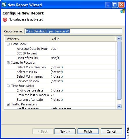
Step 5
The default report name is VLink Bandwidth per Service #1. (If you create another report instance from this report template, it is named VLink Bandwidth per Service #2, and so on. You can rename report instances.)
Step 6
a.
b.
c.
All of the virtual links that contain the string `CMTS_1' appear.
d.
The report is produced that focuses on the specified CMTS device.
5 Troubleshooting the Solution
This section describes a number of problem scenarios that you may encounter when using the solution.
Subscriber Complaints
To troubleshoot the cause of bad service to subscribers, consider the following:
•
•
To make sure the problem is not with the SCE, perform the following procedures:
Verifying the Correct Policy is Enforced on a Specific Subscriber
Step 1
In the SCE, use the show interface linecard 0 subscriber name <sub MAC> command to verify that the upvlinkId and downVlinkId values are the same as in the p3subs --show -s <sub MAC> subscriber manager CLU output and that the subscriber package ID is as expected.
The following example shows the output of the SCE CLI:
SCE2000#>show interface LineCard 0 subscriber name lynn_jonesSubscriber 'lynn_jones' manager: SMSubscriber 'lynn_jones' properties:downVlinkId=10monitor=0new_classification_policy=0packageId=0QpLimit[0..17]=0*17,8QpSet[0..17]=0*17,1upVlinkId=10...The following example shows the output of the subscriber manager CLU:
>p3subs --show -s lynn_jonesName: lynn_jonesDomain: subscribersMappings:IP: 5.101.5.129/32Properties:downVlinkId=10 Name=dev0_9_if19-downupVlinkId=10 Name=dev0_9_if19-upstream0Custom Properties:giaddr=5.101.254.105Command terminated successfullyStep 2
Compare the output of the SCE show interface linecard 0 virtual-link changed command with the subscriber manager CLU p3vlink --show-vlink-data --vlink-name <UpVlinkId/DownVlinkId Name> to make sure that the PIR configuration is correct.
Note
The following example shows the output of the SCE CLI:
SCE2000#>show interface LineCard 0 virtual-links changedVirtual Link enabledVirtual link index 1 direction upstreamGlobal Controller index 0 timebased values = 1200,1200,1200,1200...Virtual link index 10 direction upstreamGlobal Controller index 0 timebased values = 4000,4000,4000,4000...Virtual link index 1 direction downstreamGlobal Controller index 0 timebased values = 1100,1100,1100,1100...Virtual link index 10 direction downstreamGlobal Controller index 0 timebased values = 3900,3900,3900,3900...The following example shows the output of the p3vlink --show-vlink-data subscriber manager CLU:
>p3vlink --show-vlink-data --vlink-name dev0_9_if19-upstream0VLink Id: 10Direction: UpstreamSCE Name: sce0Device Name: dev0_9If Speed: 4000000Command terminated successfullyThe following example shows the output of the p3vlink --show-device subscriber manager CLU:
>p3vlink --show-device -d dev0_9Name: dev0_9IP: 10.56.196.26SCE Related: sce0Upstream factor: 100Downstream factor: 100Last success Query: Wed Dec 17 09:42:05 IST 2008Last Query Attempt: Wed Dec 17 09:42:05 IST 2008Last Query Status: CompletedSync state with SCE: doneSync state with CM: done...Command terminated successfullyTo fix this problem:
a.
b.
If Sync state with SCE is not done:
–
–
Step 3
Compare the virtual link names from the subscriber manager CLU p3subs --show -s <sub MAC> output with the CMTS configuration to verify that the subscriber is assigned to the correct CMTS and CMTS interface.
Note
Make sure that the PIR value is the same as the CMTS interface speed (as taken from the SNMP ifTable data) by comparing the virtual link PIR values from the subscriber manager CLU p3vlink --show-vlink-data --vlink-name <UpVlinkId/DownVlinkId Name> to the CMTS configuration.
To fix this problem:
a.
–
–
b.
Verifying that the Distribution of Subscribers to the Virtual Link is Correct
Step 1
Step 2
>p3vlink --show-subs --vlink-name=dev0_9_if19-upstream0Subscribers related to device: dev0_9 vlink-id: 10, giaddr: 5.101.254.100, direction UP...Subscribers related to device: dev0_9 vlink-id: 10, giaddr: 5.101.254.105, direction UP000004650424000004650425000004650429lynn_jones00000465043E...
Inaccurate, Unavailable, or Missing Reports Information for a Specific CMTS Interface
The SCA Reporter can generate per interface consumption reports that can be used to monitor the solution. The VLM updates the reporter with the interface ID to name data and the SCE sends the raw data with the interface ID (virtual link).
A problem can stem from the VLM update or from the SCE RDRs.
Two possible solutions include:
1.
2.
Verifying that the VLM Updates the Collection Manager
Step 1
View the configured network elements and verify that the collection manager exists using the subscriber manager CLU p3net --show-all --detail command.
View the subscriber manager-collection manager connection properties and state using the p3net --show -n CM_NAME command, and then verify that the SCE list property value contains the SCE to which the CMTS is connected.
To fix this problem:
a.
–
–
–
b.
Step 2
Verify that the synchronization state with collection manager is set to done using the CLU p3vlink --show-device -d <CMTS_NAME> command. To view a list of configured virtual links, use the collection manager CLU update_vlinks.sh --sce=<SCE_IP> --show command.
To fix this problem:
a.
b.
The following example shows the output of the p3net --show -n command:
>p3net --show -n cm0Network Element Information:============================Name: cm0Host: 10.56.197.231Ip: 10.56.197.231Port: 14375Status: Connection readyType: Collection ManagerSCE List: sce0Command terminated successfullyThe following example shows the output of the p3vlink --show-device -d command:
>p3vlink --show-device -d dev0_9Name: dev0_9IP: 10.56.196.26SCE Related: sce0...Sync state with SCE: doneSync state with CM: done...Command terminated successfullyThe following example shows the output of the update_vlinks.sh script:
./update_vlinks.sh --sce=10.56.197.232 --show...TIME_STAMP| SE_IP| VLINK_ID| VLINK_DIRECTION| VLINK_NAME|----------+------------------+------------------+------------------+------------------------+...2008-12-17| 10.56.197.232| 10| 0| dev0_9_if19-upstream0|2008-12-17| 10.56.197.232| 10| 1| dev0_9_if19-down|...
SCE is Congested, But Connected CMTSs are Not Congested
If the virtual link assignment is incorrect or false subscriber login operations are not handled by the correct virtual link controller, virtual links can become congested. To resolve this issue, you must confirm that there are no subscribers associated with the virtual link and also verify that the distribution of subscribers to the virtual link is as expected.
To verify that the distribution of subscribers to the virtual link is as expected, see the "Verifying that the Distribution of Subscribers to the Virtual Link is Correct" section.
Verifying that No Subscriber Is Associated with the Default Virtual Link
Step 1
Subscribers in the SCE can have a virtual link ID set to 0 in several cases:
•
•
•
The following example shows the output of the show interface LineCard 0 subscriber property upVlinkId equals 0 CLI:
SCE2000#>show interface LineCard 0 subscriber property upVlinkId equals 0N/A00000465000100000465000200000465000300000465000400000465000500000465000600000465000700000465000800000465000900000465000A00000465006F0000046500700000046500710000046500720000046500730000046500740000046500750000046500760000046500770000046500780000046500DD0000046500DE0000046500DFThe following example shows the output of the p3dhcpsniff --show-policy --policy=upVlinkId --detail CLU:
>p3dhcpsniff --show-policy --policy=upVlinkId --detailPolicy Name: upVlinkId=======================separator:_use default: falsedefault value: 0allow no package: trueconcat option:giaddr,concat option:82:1,concat option type: integer,binarylog success: truelog default success: falseNumber of mappings: 4005.101.254.100_00010000=95.101.254.100_00010003=105.101.254.100_80010000=95.101.254.100_80010003=105.101.254.101_00010000=95.101.254.101_00010003=105.101.254.101_80010000=95.101.254.101_80010003=105.101.254.102_00010000=95.101.254.102_00010003=105.101.254.102_80010000=95.101.254.102_80010003=105.101.254.103_00010000=95.101.254.103_00010003=105.101.254.103_80010000=95.101.254.103_80010003=105.101.254.104_00010000=95.101.254.104_00010003=105.101.254.104_80010000=95.101.254.104_80010003=105.101.254.105_00010000=95.101.254.105_00010003=105.101.254.105_80010000=95.101.254.105_80010003=105.101.254.106_00010000=95.101.254.106_00010003=105.101.254.106_80010000=9
Userlog Messages
Table 3 lists the messages that can be written to the userlog.
6 Obtaining Documentation and Submitting a Service Request
For information on obtaining documentation, submitting a service request, and gathering additional information, see the monthly What's New in Cisco Product Documentation, which also lists all new and revised Cisco technical documentation, at:
http://www.cisco.com/en/US/docs/general/whatsnew/whatsnew.html
Subscribe to the What's New in Cisco Product Documentation as a Really Simple Syndication (RSS) feed and set content to be delivered directly to your desktop using a reader application. The RSS feeds are a free service and Cisco currently supports RSS Version 2.0.
CCDE, CCENT, Cisco Eos, Cisco HealthPresence, the Cisco logo, Cisco Lumin, Cisco Nexus, Cisco StadiumVision, Cisco TelePresence, Cisco WebEx, DCE, and Welcome to the Human Network are trademarks; Changing the Way We Work, Live, Play, and Learn and Cisco Store are service marks; and Access Registrar, Aironet, AsyncOS, Bringing the Meeting To You, Catalyst, CCDA, CCDP, CCIE, CCIP, CCNA, CCNP, CCSP, CCVP, Cisco, the Cisco Certified Internetwork Expert logo, Cisco IOS, Cisco Press, Cisco Systems, Cisco Systems Capital, the Cisco Systems logo, Cisco Unity, Collaboration Without Limitation, EtherFast, EtherSwitch, Event Center, Fast Step, Follow Me Browsing, FormShare, GigaDrive, HomeLink, Internet Quotient, IOS, iPhone, iQuick Study, IronPort, the IronPort logo, LightStream, Linksys, MediaTone, MeetingPlace, MeetingPlace Chime Sound, MGX, Networkers, Networking Academy, Network Registrar, PCNow, PIX, PowerPanels, ProConnect, ScriptShare, SenderBase, SMARTnet, Spectrum Expert, StackWise, The Fastest Way to Increase Your Internet Quotient, TransPath, WebEx, and the WebEx logo are registered trademarks of Cisco Systems, Inc. and/or its affiliates in the United States and certain other countries.
All other trademarks mentioned in this document or website are the property of their respective owners. The use of the word partner does not imply a partnership relationship between Cisco and any other company. (0812R)
Any Internet Protocol (IP) addresses used in this document are not intended to be actual addresses. Any examples, command display output, and figures included in the document are shown for illustrative purposes only. Any use of actual IP addresses in illustrative content is unintentional and coincidental.
© 2009 Cisco Systems, Inc. All rights reserved.
 Feedback