Release Notes for the Cisco uBR10012 Universal Broadband Router for Cisco IOS Release 12.3BC
Available Languages
Table Of Contents
Release Notes for Cisco uBR10012 Universal Broadband Router for Cisco IOS Release 12.3BC
DOCSIS System Interoperability on the Cisco uBR10012 CMTS
Cisco IOS Release 12.3(13a)BC and DOCSIS 1.1 System Interoperability
DOCSIS 1.0 and 1.0+ Extensions
Determining the Software Version
Upgrading to a New Software Release
New Hardware Features in Cisco IOS Release 12.3(23)BC10
New Software Features in Cisco IOS Release 12.3(23)BC10
New Hardware Features in Cisco IOS Release 12.3(23)BC9
New Software Features in Cisco IOS Release 12.3(23)BC9
Open Source Software Licenses for Cisco Universal Broadband Routers
New Hardware Features in Cisco IOS Release 12.3(21a)BC9
New Software Features in Cisco IOS Release 12.3(21a)BC9
New Hardware Features in Cisco IOS Release 12.3(23)BC8
New Software Features in Cisco IOS Release 12.3(23)BC8
New Hardware Features in Cisco IOS Release 12.3(23)BC7
New Software Features in Cisco IOS Release 12.3(23)BC7
SAMIS CLC-RP Traffic Throttling
New Hardware Features in Cisco IOS Release 12.3(23)BC6
New Software Features in Cisco IOS Release 12.3(23)BC6
New Hardware Features in Cisco IOS Release 12.3(23)BC5
New Software Features in Cisco IOS Release 12.3(23)BC5
New Hardware Features in Cisco IOS Release 12.3(23)BC4
New Software Features in Cisco IOS Release 12.3(23)BC4
New Hardware Features in Cisco IOS Release 12.3(21a)BC8
New Software Features in Cisco IOS Release 12.3(21a)BC8
New Hardware Features in Cisco IOS Release 12.3(23)BC3
New Software Features in Cisco IOS Release 12.3(23)BC3
New Hardware Features in Cisco IOS Release 12.3(23)BC2
New Software Features in Cisco IOS Release 12.3(23)BC2
Subscriber Traffic Management (STM) Version 1.2
Upstream Utilization Optimization
New Hardware Features in Cisco IOS Release 12.3(21a)BC7
New Software Features in Cisco IOS Release 12.3(21a)BC7
New Hardware Features in Cisco IOS Release 12.3(23)BC1
New Software Features in Cisco IOS Release 12.3(23)BC1
PacketCable Subscriber ID Support
MxN MAC Domain DS Load Balancing
Line Card High Availability (HA) Support for WB Cable Modems
Bypass the 24 Hour Timer for WB CM Use of Failed RF Channels
Dynamic Bandwidth Sharing for Wideband and Modular Cable Interfaces
New Hardware Features in Cisco IOS Release 12.3(21a)BC6
New Software Features in Cisco IOS Release 12.3(21a)BC6
New Hardware Features in Cisco IOS Release 12.3(21a)BC5
New Software Features in Cisco IOS Release 12.3(21a)BC5
New Hardware Features in Cisco IOS Release 12.3(23)BC
DOCSIS Timing & Control Card (DTCC)
New Software Features in Cisco IOS Release 12.3(23)BC
DOCSIS 3.0 Downstream Solution
New Hardware Features in Cisco IOS Release 12.3(21a)BC4
New Software Features in Cisco IOS Release 12.3(21a)BC4
New Hardware Features in Cisco IOS Release 12.3(17b)BC9
New Software Features in Cisco IOS Release 12.3(17b)BC9
New Hardware Features in Cisco IOS Release 12.3(21a)BC3
New Software Features in Cisco IOS Release 12.3(21a)BC3
New Hardware Features in Cisco IOS Release 12.3(21a)BC2
New Software Features in Cisco IOS Release 12.3(21a)BC2
New Hardware Features in Cisco IOS Release 12.3(21a)BC1
New Software Features in Cisco IOS Release 12.3(21a)BC1
New Hardware Features in Cisco IOS Release 12.3(21)BC
New Software Features in Cisco IOS Release 12.3(21)BC
Automatic Virtual Interface Bundles
Cable Duplicate MAC Address Reject
DOCSIS 3.0 Downstream Channel Bonding
Enhanced Rate Bandwidth Allocation (ERBA) on the Cisco uBR10012 Router
PacketCable Client Accept Timeout
Per Downstream Static Multicast
RF Switch Firmware Version 3.60
SAMIS Source Address Management
Service Flow Admission Control
Stateful Switchover (SSO) for PacketCable and PacketCable MultiMedia
New Hardware Features in Cisco IOS Release 12.3(17b)BC8
New Software Features in Cisco IOS Release 12.3(17b)BC8
New Hardware Features in Cisco IOS Release 12.3(17b)BC7
New Software Features in Cisco IOS Release 12.3(17b)BC7
New Hardware Features in Cisco IOS Release 12.3(17b)BC6
New Software Features in Cisco IOS Release 12.3(17b)BC6
New Hardware Features in Cisco IOS Release 12.3(17b)BC5
New Software Features in Cisco IOS Release 12.3(17b)BC5
New Hardware Features in Cisco IOS Release 12.3(17b)BC4
Cisco uBR10-MC5X20H Interface Line Card
New Software Features in Cisco IOS Release 12.3(17b)BC4
Downstream Load Balancing Distribution with Upstream Load Balancing
New Hardware Features in Cisco IOS Release 12.3(17b)BC3
New Software Features in Cisco IOS Release 12.3(17b)BC3
New Hardware Features in Cisco IOS Release 12.3(17a)BC2
New Software Features in Cisco IOS Release 12.3(17a)BC2
Cisco Advanced-Mode DOCSIS Set-Top Gateway 1.2 for the Cisco CMTS
New Hardware Features in Cisco IOS Release 12.3(17a)BC1
New Software Features in Cisco IOS Release 12.3(17a)BC1
New Hardware Features in Cisco IOS Release 12.3(17a)BC
New Software Features in Cisco IOS Release 12.3(17a)BC
DSX Messages and Synchronized PHS Information
Dynamic Channel Change (DCC) for Load Balancing
Generic Routing Encapsulation (GRE) Tunneling on the Cisco uBR10012
Globally Configured HCCP 4+1 and 7+1 Redundancy on the Cisco uBR10012 Router
High Availability Support for Encrypted IP Multicast
Management Information Base (MIB) Changes and Enhancements
Pre-equalization Control for Cable Modems
show cable modem Command Changes
Secure Socket Layer Server for Usage-Based Billing
New Hardware Features in Cisco IOS Release 12.3(13a)BC6
New Software Features in Cisco IOS Release 12.3(13a)BC6
New Hardware Features in Cisco IOS Release 12.3(13a)BC5
New Software Features in Cisco IOS Release 12.3(13a)BC5
New Hardware Features in Cisco IOS Release 12.3(13a)BC4
New Software Features in Cisco IOS Release 12.3(13a)BC4
New Hardware Features in Cisco IOS Release 12.3(13a)BC3
New Software Features in Cisco IOS Release 12.3(13a)BC3
New Hardware Features in Cisco IOS Release 12.3(13a)BC2
New Software Features in Cisco IOS Release 12.3(13a)BC2
New Hardware Features in Cisco IOS Release 12.3(13a)BC1
New Software Features in Cisco IOS Release 12.3(13a)BC1
New Hardware Features in Cisco IOS Release 12.3(13a)BC
Cisco Half-Height Gigabit Ethernet Line Card
Processor/IO Memory for the PRE1 Route Processor Module
Cisco uBR10-MC5X20S/U Broadband Processing Engine
Cisco uBR10012 Performance Routing Engine 2 (PRE2) Modules
New Software Features for Cisco IOS Release 12.3(13a)BC
Access Control List Support for COPS Intercept
Admission Control for the Cisco CMTS
Advanced-mode DOCSIS Set-Top Gateway Issue 1.1
Advanced Spectrum Management Support on the Cisco uBR10012 CMTS
Backup Path Testing for the Cisco RF Switch
Cable Monitor Support for Cisco MC5x20U-D and Cisco MC28U Broadband Processing Engines
COPS TCP Support for the Cisco Cable Modem Termination System
DHCP MAC Address Exclusion List for cable-source verify dhcp Command
DOCSIS 1.0 Concatenation Override
DOCSIS BPI+ Multiple Root Certificate Support
Dynamic SID/VRF Mapping Support
Enhanced Rate Bandwidth Allocation (ERBA) Support for DOCSIS 1.0 Cable Modems
Multicast QoS Support on the Cisco uBR10012 CMTS
Online Offline Diagnostics (OOD) Support for the Cisco uBR10012 Universal Broadband Router
Optional Upstream Scheduler Modes
PacketCable Emergency 911 Cable Interface Line Card Prioritization
PacketCable Emergency 911 Services Listing and History
PacketCable Multimedia for the Cisco CMTS
Service Independent Intercept (SII) Support
Transparent LAN Service and Layer 2 Virtual Private Networks
Virtual Interface Bundling on the Cisco uBR10-MC5X20S/U BPE
New Hardware Features in Cisco IOS Release 12.3(9a)BC9
New Software Features in Cisco IOS Release 12.3(9a)BC9
New Hardware Features in Cisco IOS Release 12.3(9a)BC8
New Software Features in Cisco IOS Release 12.3(9a)BC8
New Hardware Features in Cisco IOS Release 12.3(9a)BC7
New Software Features in Cisco IOS Release 12.3(9a)BC7
New Hardware Features in Cisco IOS Release 12.3(9a)BC6
New Software Features in Cisco IOS Release 12.3(9a)BC6
New Hardware Features in Cisco IOS Release 12.3(9a)BC5
New Software Features in Cisco IOS Release 12.3(9a)BC5
New Hardware Features in Cisco IOS Release 12.3(9a)BC4
New Software Features in Cisco IOS Release 12.3(9a)BC4
New Hardware Features in Cisco IOS Release 12.3(9a)BC3
New Software Features in Cisco IOS Release 12.3(9a)BC3
New Hardware Features in Cisco IOS Release 12.3(9a)BC2
New Software Features in Cisco IOS Release 12.3(9a)BC2
New Hardware Features in Cisco IOS Release 12.3(9a)BC1
New Software Features in Cisco IOS Release 12.3(9a)BC1
New Hardware Features in Cisco IOS Release 12.3(9a)BC
Cisco uBR10-MC5X20S/U Broadband Processing Engine
Cisco uBR10012 Performance Routing Engine 2 (PRE2) Modules
DOCSIS System Interoperability on the Cisco uBR10012 CMTS
New Software Features for Cisco IOS Release 12.3(9a)BC
Cisco Broadband Troubleshooter 3.2
Cisco CMTS Static CPE Override
Cisco IOS Release 12.3(9a)BC Command-Line Interface (CLI) Enhancements
DOCSIS Set-Top Gateway Issue 1.0
Dynamic Shared Secret (DMIC) with OUI Exclusion
EtherChannel Support on the Cisco uBR10012 Universal Broadband Router
MIBs Changes and Updates in Cisco IOS Release 12.3(9a)BC
NetFlow Accounting Versions 5 and 8 Support
NetFlow Version 5 Features and Format
NetFlow Version 8 Features and Format
Additional Information about NetFlow on the Cisco CMTS
SFID Support for Multicast and Cable Interface Bundling
CBT 3.2 Spectrum Management Support with the Cisco uBR10-MC5X20S/U BPE
Subscriber Traffic Management (STM) Version 1.1
Transparent LAN Service (TLS) on the Cisco uBR10012 Router with IEEE 802.1Q
Virtual Interface and Frequency Stacking Support on the Cisco uBR10-MC5X20S/U BPE
Virtual Interface Support for HCCP N+1 Redundancy
MIB Changes and Enhancements for Cisco IOS Release 12.3(21)BC:
MIB Changes and Enhancements for Cisco IOS Release 12.3(17a)BC:
How to Upgrade to Cisco IOS Release 12.3(21)BC
New Command Information for Cisco IOS Release 12.3(21)BC
Restrictions for Cisco IOS Release 12.3(17a)BC
New Command Information for Cisco IOS Release 12.3(13a)BC3
New Command Information for Cisco IOS Release 12.3(13a)BC2
cable service flow activity-timeout
Restrictions for Cisco IOS Release 12.3(13a)BC
Restrictions for Cisco IOS Release 12.3(9a)BC
New and Changed Command Reference for Cisco IOS Release 12.3(9a)BC
Caveats for Cisco IOS Release 12.3 BC
Open Caveats for Release 12.3(23)BC10
Resolved Caveats for Release 12.3(23)BC10
Open Caveats for Release 12.3(23)BC9
Resolved Caveats for Release 12.3(23)BC9
Open Caveats for Release 12.3(21a)BC9
Resolved Caveats for Cisco 12.3(21a)BC9
Open Caveats for Release 12.3(23)BC8
Resolved Caveats for Release 12.3(23)BC8
Open Caveats for Release 12.3(23)BC7
Resolved Caveats for Release 12.3(23)BC7
Open Caveats for Release 12.3(23)BC6
Resolved Caveats for Release 12.3(23)BC6
Open Caveats for Release 12.3(23)BC5
Resolved Caveats for Release 12.3(23)BC5
Open Caveats for Release 12.3(23)BC4
Resolved Caveats for Release 12.3(23)BC4
Open Caveats for Release 12.3(21a)BC8
Resolved Caveats for Release 12.3(21a)BC8
Open Caveats for Release 12.3(23)BC3
Resolved Caveats for Release 12.3(23)BC3
Open Caveats for Release 12.3(23)BC2
Resolved Caveats for Release 12.3(23)BC2
Open Caveats for Release 12.3(21a)BC7
Resolved Caveats for Release 12.3(21a)BC7
Open Caveats for Release 12.3(23)BC1
Resolved Caveats for Release 12.3(23)BC1
Open Caveats for Release 12.3(21a)BC6
Resolved Caveats for Release 12.3(21a)BC6
Open Caveats for Release 12.3(21a)BC5
Resolved Caveats for Release 12.3(21a)BC5
Open Caveats for Release 12.3(23)BC
Resolved Caveats for Release 12.3(23)BC
Open Caveats for Release 12.3(21a)BC4
Resolved Caveats for Release 12.3(21a)BC4
Open Caveats for Release 12.3(17b)BC9
Resolved Caveats for Release 12.3(17b)BC9
Open Caveats for Release 12.3(21a)BC3
Resolved Caveats for Release 12.3(21a)BC3
Open Caveats for Release 12.3(21a)BC2
Resolved Caveats for Release 12.3(21a)BC2
Open Caveats for Release 12.3(21a)BC1
Resolved Caveats for Release 12.3(21a)BC1
Open Caveats for Release 12.3(21)BC
Resolved Caveats for Release 12.3(21)BC
Open Caveats for Release 12.3(17b)BC8
Resolved Caveats for Release 12.3(17b)BC8
Open Caveats for Release 12.3(17b)BC7
Resolved Caveats for Release 12.3(17b)BC7
Open Caveats for Release 12.3(17b)BC6
Resolved Caveats for Release 12.3(17b)BC6
Open Caveats for Release 12.3(17b)BC5
Resolved Caveats for Release 12.3(17b)BC5
Open Caveats for Release 12.3(17b)BC4
Resolved Caveats for Release 12.3(17b)BC4
Open Caveats for Release 12.3(17b)BC3
Resolved Caveats for Release 12.3(17b)BC3
Open Caveats for Release 12.3(17a)BC2
Resolved Caveats for Release 12.3(17a)BC2
Open Caveats for Release 12.3(17a)BC1
Resolved Caveats for Release 12.3(17a)BC1
Open Caveats for Release 12.3(17a)BC
Resolved Caveats for Release 12.3(17a)BC
Open Caveats for Release 12.3(13a)BC6
Resolved Caveats for Release 12.3(13a)BC6
Open Caveats for Release 12.3(13a)BC5
Resolved Caveats for Release 12.3(13a)BC5
Open Caveats for Release 12.3(13a)BC4
Resolved Caveats for Release 12.3(13a)BC4
Open Caveats for Release 12.3(13a)BC3
Resolved Caveats for Release 12.3(13a)BC3
Open Caveats for Release 12.3(13a)BC2
Resolved Caveats for Release 12.3(13a)BC2
Open Caveats for Release 12.3(13a)BC1
Resolved Caveats for Release 12.3(13a)BC1
Open Caveats for Release 12.3(13a)BC
Resolved Caveats for Release 12.3(13a)BC
Open Caveats for Release 12.3(9a)BC9
Resolved Caveats for Release 12.3(9a)BC9
Open Caveats for Release 12.3(9a)BC8
Resolved Caveats for Release 12.3(9a)BC8
Open Caveats for Release 12.3(9a)BC7
Resolved Caveats for Release 12.3(9a)BC7
Open Caveats for Release 12.3(9a)BC6
Resolved Caveats for Release 12.3(9a)BC6
Open Caveats for Release 12.3(9a)BC5
Resolved Caveats for Release 12.3(9a)BC5
Open Caveats for Release 12.3(9a)BC4
Resolved Caveats for Release 12.3(9a)BC4
Open Caveats for Release 12.3(9a)BC3
Resolved Caveats for Release 12.3(9a)BC3
Open Caveats for Release 12.3(9a)BC2
Resolved Caveats for Release 12.3(9a)BC2
Open Caveats for Release 12.3(9a)BC1
Resolved Caveats for Release 12.3(9a)BC1
Open Caveats for Release 12.3(9a)BC
Resolved Caveats for Release 12.3(9a)BC
Cisco IOS Software Documentation Set
Release 12.3 Documentation Set
Obtaining Documentation, Obtaining Support, and Security Guidelines
Release Notes for Cisco uBR10012 Universal Broadband Router for Cisco IOS Release 12.3BC
Revised: February 28, 2011, OL-6760-49
The release notes for Cisco IOS Release 12.3BC for the Cisco uBR10012 universal broadband routers describe the enhancements and caveats for all releases in the cable-specific, early deployment, 12.3BC release trains. Some of the most recent releases in 12.3BC include 12.3(17b)BCx-, 12.3(21a)BCx-, and 12.3(23)BCx-based releases.
These release notes are updated with each release in the train. For a list of the software caveats that apply to Cisco IOS Release 12.3(23)BC8, see the "Caveats for Cisco IOS Release 12.3 BC" section and Caveats for Cisco IOS Release 12.3 T. Use these release notes in conjunction with the cross-platform Release Notes for Cisco IOS Release 12.3T located on Cisco.com and the Documentation CD-ROM.
Use these release notes with Cross-Platform Release Notes for Cisco IOS Release 12.3 T located on Cisco.com.
Cisco recommends that you view the field notices for this release to see if your software or hardware platforms are affected. If you have an account on Cisco.com, you can find field notices at http://www.cisco.com/en/US/customer/support/tsd_products_field_notice_summary.html. If you do not have a Cisco.com login account, you can find field notices at http://www.cisco.com/en/US/support/tsd_products_field_notice_summary.html.
Contents
These release notes describe the following topics:
•
DOCSIS System Interoperability on the Cisco uBR10012 CMTS
•
•
•
Early Deployment Releases
These release notes describe the Cisco uBR10012 universal broadband router for Cisco IOS Release 12.3(21a)BC9, which is an early deployment (ED) release based on Cisco IOS Release 12.3 T. Early deployment releases contain fixes for software caveats and support for new Cisco hardware and software features.
Table 1 shows recent early deployment releases for the CiscouBR10012 universal broadband router.
System Requirements
This section describes the system requirements for Cisco IOS Release upto 12.3(23)BC8 and includes the following sections:
•
•
•
Memory Recommendations
Supported Hardware
This section describes the hardware supported by the Cisco uBR10012 Universal Broadband Router in Cisco IOS Release 12.3(21a)BC9.
For detailed descriptions of the new hardware features, see the "New and Changed Information" section.
Table 3 provides the list of hardware supported by the Cisco uBR10012 Universal Broadband Router.

Note
DOCSIS System Interoperability on the Cisco uBR10012 CMTS
This section describes the operation of primary interoperability features in the Cisco uBR10012 router. For additional DOCSIS information, refer to the following document on Cisco.com:
•
http://www.cisco.com/en/US/docs/cable/cmts/feature/guide/ufg_docs.html
Cisco IOS Release 12.3(13a)BC and DOCSIS 1.1 System Interoperability
Cisco IOS Release 12.3(13a)BC and earlier releases in this release train support several powerful new features for the Cisco uBR10012 CMTS. In addition to maintaining DOCSIS support from earlier Cisco IOS releases, Cisco IOS Release 12.3(13a)BC enhances DOCSIS support in these general categories:
•
http://www.cablemodem.com/specifications/specifications20.html
•
http://www.cablelabs.com/cablemodem/specifications/gateway.html
•
http://www.cablelabs.com/packetcable/specifications/
•
–
http://www.cablelabs.com/packetcable/specifications/multimedia.html
Additional High Availability and Security features as described elsewhere in this document.
DOCSIS 1.0 Baseline Privacy
DOCSIS baseline privacy interface (BPI) gives subscribers data privacy across the RF network, encrypting traffic flows between the CMTS and cable modem. BPI ensures that a cable modem, uniquely identified by its Media Access Control (MAC) address, can obtain keying material for services only it is authorized to access.
To enable BPI, choose software at both the CMTS and cable modem that support this mode of operation. Select a Cisco IOS image that supports BPI. BPI must be enabled using the DOCSIS configuration file.
The cable modem must also support BPI. Cable modems must have factory-installed RSA private/public key pairs to support internal algorithms to generate key pairs prior to first BPI establishment.
Note
Cable Modem Interoperability
•
•
DOCSIS 1.0 and 1.0+ Extensions
Earlier releases of Cisco IOS software for the uBR10012 router provide support for the original DOCSIS 1.0 standard, featuring basic best-effort data traffic and Internet access over the coaxial cable network. The DOCSIS 1.0+ extensions provides Quality of Service (QoS) enhancements for real-time traffic, such as voice calls, in anticipation of full DOCSIS 1.1 support.
Note
DOCSIS 1.1 Extensions
The DOCSIS 1.1 specification provides the following functional enhancements over DOCSIS 1.0 coaxial cable networks:
•
–
–
–
–
–
•
–
–
–
–
–
•
•
•
•
•
DOCSIS 1.1 Quality of Service
The DOCSIS 1.1 QoS framework is based on the following objects:
•
•
•
•
In DOCSIS 1.1, the basic unit of QoS is the service flow, which is a unidirectional sequence of packets transported across the RF interface between the cable modem and CMTS. A service flow is characterized by a set of QoS parameters such as latency, jitter, and throughput assurances.
Every cable modem establishes a primary service flow in both the upstream and downstream directions. The primary flows maintain connectivity between the cable modem and CMTS at all times.
In addition, a DOCSIS 1.1 cable modem can establish multiple secondary service flows. The secondary service flows can either be permanently created (they persist until the cable modem is reset or powered off) or they can be created dynamically to meet the needs of the on demand traffic being transmitted.
Each service flow has a set of QoS attributes associated with it. These QoS attributes define a particular class of service and determine characteristics such as the maximum bandwidth for the service flow and the priority of its traffic. The class of service attributes can be inherited from a preconfigured CMTS local service class (class-based flows), or they can be individually specified at the time of the creation of the service flow.
Each service flow has multiple packet classifiers associated with it, which determine the type of application traffic allowed to be sent on that service flow. Each service flow can also have a Payload header suppression (PHS) rule associated with it to determine which portion of the packet header will be suppressed when packets are transmitted on the flow.
Determining the Software Version
To determine the version of Cisco IOS software running on your Cisco uBR10012 universal broadband router, log in to the Cisco uBR10012 universal broadband router and enter the show version EXEC command:
Router> show versionCisco Internetwork Operating System SoftwareIOS (tm) Software (uBR10k-k8p6-mz), Version 12.3(17b)BC9, EARLY DEPLOYMENT RELEASE SOFTWAREUpgrading to a New Software Release
For information about selecting a new Cisco IOS software release, please refer to How to Choose a Cisco IOS Software Release at:
http://www.cisco.com/en/US/partner/products/sw/iosswrel/ps1834/products_tech_note09186a00800fb9d9.shtml
For information about upgrading to a new software release, refer to the appropriate platform-specific document:
•
•
http://www.cisco.com/warp/public/cc/pd/iosw/prodlit/957_pp.htm
To choose a new Cisco IOS software release by comparing feature support or memory requirements, use Cisco Feature Navigator. Cisco Feature Navigator is a web-based tool that enables you to determine which Cisco IOS and Catalyst OS software images support a specific set of features and which features are supported in a specific Cisco IOS image. You can search by feature or by feature set (software image). Under the release section, you can compare Cisco IOS software releases side by side to display both the features unique to each software release and the features that the releases have in common.
Cisco Feature Navigator is updated regularly when major Cisco IOS software releases and technology releases occur. For the most current information, go to the Cisco Feature Navigator home page at the following URL:
To choose a new Cisco IOS software release based on information about defects that affect that software, use Bug Toolkit at:
http://tools.cisco.com/Support/BugToolKit/action.do?hdnAction=searchBugs
Feature Set Tables
Cisco IOS software is packaged in feature sets that consist of software images that support specific platforms. The feature sets available for a specific platform depend on which Cisco IOS software images are included in a release. Each feature set contains a specific set of Cisco IOS features.

Caution
The feature set tables have been removed from the Cisco IOS Release 12.3 release notes to improve the usability of the release notes documentation. The feature-to-image mapping that was provided by the feature set tables is available through Cisco Feature Navigator.
Cisco Feature Navigator is a web-based tool that enables you to determine which Cisco IOS software images support a specific set of features and which features are supported in a specific Cisco IOS image. You can search by feature or by feature set (software image). Under the release section, you can compare Cisco IOS software releases side by side to display both the features unique to each software release and the features that the releases have in common.
To access Cisco Feature Navigator, you must have an account on Cisco.com. If you have forgotten or lost your account information, send a blank e-mail to cco-locksmith@cisco.com. An automatic check will verify that your e-mail address is registered with Cisco.com. If the check is successful, account details with a new random password will be e-mailed to you. Qualified users can establish an account on Cisco.com by following the directions found at this URL:
http://www.cisco.com/web/siteassets/account/index.html
Cisco Feature Navigator is updated regularly when major Cisco IOS software releases and technology releases occur. For the most current information, go to the Cisco Feature Navigator home page at the following URL:
For frequently asked questions about Cisco Feature Navigator, see the FAQs at the following URL:
http://www.cisco.com/support/FeatureNav/FNFAQ.html
Determining Which Software Images (Feature Sets) Support a Specific Feature
To determine which software images (feature sets) in Cisco IOS Release 12.3 support a specific feature, go to the Cisco Feature Navigator home page, enter your Cisco.com login, and perform the following steps:
Step 1
Step 2
Step 3
Note
Repeat this step to add additional features. A maximum of 20 features can be chosen for a single search.
Step 4
Step 5
Step 6
Step 7
Determining Which Features Are Supported in a Specific Software Image (Feature Set)
To determine which features are supported in a specific software image (feature set) in Cisco IOS Release 12.3, go to the Cisco Feature Navigator home page, enter your Cisco.com login, and perform the following steps:
Step 1
Step 2
Step 3
Step 4
Step 5
Step 6
New and Changed Information
The following sections list the new hardware and software features supported by the Cisco uBR10012 router for Cisco IOS Release 12.3(21a)BC9:
For more information about these features, refer to the documents listed in the "Related Documentation" section.
New Hardware Features in Cisco IOS Release 12.3(23)BC10
There are no new hardware features in Cisco IOS Release 12.3(23)BC10.
New Software Features in Cisco IOS Release 12.3(23)BC10
There are no new software features in Cisco IOS Release 12.3(23)BC10.
New Hardware Features in Cisco IOS Release 12.3(23)BC9
There are no new hardware features supported in Cisco IOS Release 12.3(23)BC9.
New Software Features in Cisco IOS Release 12.3(23)BC9
There are no new software features supported in Cisco IOS Release 12.3(23)BC9.
Open Source Software Licenses for Cisco Universal Broadband Routers
For information on Open Source Software License MPL 1.1, refer to the following URL:
http://www.cisco.com/en/US/docs/cable/cmts/license/cable_licensing.html
New Hardware Features in Cisco IOS Release 12.3(21a)BC9
There is no new hardware feature supported in Cisco IOS Release 12.3(21a)BC9.
New Software Features in Cisco IOS Release 12.3(21a)BC9
There is no new software feature supported in Cisco IOS Release 12.3(21a)BC9.
New Hardware Features in Cisco IOS Release 12.3(23)BC8
There is no new hardware feature supported in Cisco IOS Release 12.3(23)BC8.
New Software Features in Cisco IOS Release 12.3(23)BC8
There is no new software feature supported in Cisco IOS Release 12.3(23)BC8.
New Hardware Features in Cisco IOS Release 12.3(23)BC7
There is no new hardware feature supported in Cisco IOS Release 12.3(23)BC7.
New Software Features in Cisco IOS Release 12.3(23)BC7
The following software features are new in Cisco IOS Release 12.3(23)BC7.
SAMIS CLC-RP Traffic Throttling
The SAMIS CLC-RP traffic throttling feature limits or throttles the data collection between the cable line card and the route processor. This functionality is achieved using the new cable metering data-per-session command. This feature also reduces the congestion in the Broadband Processing Engine (BPE) due to the SAMIS data collection from CLC to RP.
The following commands are new or modified:
•
•
•
M-CMTS Enhancement
The following commands are modified in Cisco IOS Release 12.3(23)BC7. The commands are upgraded to provide better display of the route processor service flow and queue information.
•
•
Three Step Dynamic Modulation
Cisco IOS Release 12.3(33)BC7 introduces Three Step Dynamic Modulation, which allows you to create and use a third modulation profile in the Dynamic Upstream Modulation feature, as against the existing 16-QAM and quadrature phase-shift keying (QPSK) modulation profiles. The feature now permits 64-QAM based modulation profile to increase the upstream throughput and to satisfy the demand for new spectrum management.
The 64-QAM modulation profile is a more bandwidth-efficient modulation scheme and has a higher throughput than the other two modulation profiles.
For more details on Three Step Dynamic Modulation and the Dynamic Upstream Modulation feature, refer to Spectrum Management and Advanced Spectrum Management for the Cisco CMTS guide at the following location: http://www.cisco.com/en/US/docs/cable/cmts/feature/guide/ufg_spec.html.
The Cisco IOS Release 12.3(23)BC7 introduces or modifies the following commands:
The cable upstream threshold hysteresis command was introduced to allow configurable hysteresis values for spectrum management channel upgrade thresholds.
The cable upstream modulation command was enhanced to accept up to three profiles, instead of the existing two.
The show cable hop history command was enhanced to display the modulation profile number when a change occurs.
Enhanced Show Tech
A new keyword, cmts, has been added to the show tech-support command to provide debugging information specific to a cable interface or a modem for the following universal broadband routers:
•
•
•
For details about this command, see the Cisco IOS CMTS Cable Command Reference at the following URL:
http://www.cisco.com/en/US/docs/ios/cable/command/reference/cbl_16_show_cable_m_to_show_cable_u.html
Cable Modem QoS Information
A new command, show cable modem service-flow, is introduced to provide information about all service flows associated with a particular modem.
For details about this command, see the Cisco IOS CMTS Cable Command Reference at the following URL:
http://www.cisco.com/en/US/docs/ios/cable/command/reference/cbl_16_show_cable_m_to_show_cable_u.html
Direct Load for Cable Modems
A new command, cable upstream equalization-error-recovery, is introduced to enable the CMTS to send Type-Length-Value (TLV) Type 9 in the DOCSIS RNG-RSP MAC management messages. The TLV Type 9 helps CMs come online if the TLV Type 4 convolved method causes CMs to go offline.
For details about this command, see the Cisco IOS CMTS Cable Command Reference at the following URL:
http://www.cisco.com/en/US/docs/ios/cable/command/reference/cbl_10_cable_u_to_cable_w.html
New Hardware Features in Cisco IOS Release 12.3(23)BC6
There are no new hardware features supported in Cisco IOS Release 12.3(23)BC6.
New Software Features in Cisco IOS Release 12.3(23)BC6
The following command is modified in Cisco IOS Release 12.3(23)BC6:
•
The command output was modified to capture the SPA sensor temperature readings and error packet information.
The error information contains details about the:
•
•
•
•
For additional information about this or other commands, refer to the Cisco IOS CMTS Cable Command Reference at http://www.cisco.com/en/US/docs/ios/cable/command/reference/cbl_book.html
New Hardware Features in Cisco IOS Release 12.3(23)BC5
There are no new hardware features supported in Cisco IOS Release 12.3(23)BC5.
New Software Features in Cisco IOS Release 12.3(23)BC5
The following command is modified in Cisco IOS Release 12.3(23)BC5:
•
The command output was modified to capture the SPA sensor temperature readings and error packet information.
The error information contains details about the:
•
•
•
•
New Hardware Features in Cisco IOS Release 12.3(23)BC4
There are no new hardware features supported in Cisco IOS Release 12.3(23)BC4.
New Software Features in Cisco IOS Release 12.3(23)BC4
There are no new software features supported in Cisco IOS Release 12.3(23)BC4.
New Hardware Features in Cisco IOS Release 12.3(21a)BC8
There are no new hardware features supported in Cisco IOS Release 12.3(21a)BC8.
New Software Features in Cisco IOS Release 12.3(21a)BC8
There are no new software features supported in Cisco IOS Release 12.3(21a)BC8.
New Hardware Features in Cisco IOS Release 12.3(23)BC3
There are no new hardware features supported in Cisco IOS Release 12.3(23)BC3.
New Software Features in Cisco IOS Release 12.3(23)BC3
There are no new software features supported in Cisco IOS Release 12.3(23)BC3.
New Hardware Features in Cisco IOS Release 12.3(23)BC2
There are no new hardware features supported in Cisco IOS Release 12.3(23)BC2.
New Software Features in Cisco IOS Release 12.3(23)BC2
The following software features are new in Cisco IOS Release 12.3(23)BC2.
Subscriber Traffic Management (STM) Version 1.2
The STM feature enables service providers to identify and control subscribers who exceed the maximum bandwidth allowed under their registered quality of service (QoS) profiles. STM is a simple bandwidth management tool which works as a low CPU alternative to Network-Based Application Recognition (NBAR) and access control lists (ACLs), however, using STM does not mean that NBAR and ACLs have to be turned off; STM can be applied along with NBAR and ACLs. STM also works in conjunction with the Cisco Broadband Troubleshooter to support additional network management and troubleshooting functions in the Cisco CMTS.
The STM Version 1.2 feature is enhanced in Cisco IOS Release 12.3(23)BC2 with the following support on the Cisco uBR7246VXR and Cisco uBR10012 Universal Broadband Routers:
•
•
•
•
•
Addition of the following SNMP objects to the CISCO-CABLE-QOS-MONITOR-MIB:
•
•
•
•
•
•
•
•
•
•
•
•
•
•
The following commands are new or modified:
•
•
•
•
•
•
For detailed information about this feature, see the Subscriber Traffic Management on the Cisco CMTS Routers document at:
http://www.cisco.com/en/US/docs/ios/cable/configuration/guide/cmts_sbsbr_tfmgt.html
Upstream Utilization Optimization
The Upstream (US) Utilization Optimization feature on the Cisco Cable Modem Termination System (CMTS) routers provides higher upstream throughput. It provides the following benefits and functions on a Cisco CMTS router:
•
•
The following commands are new or modified:
•
•
•
•
•
For detailed information about this feature, see the Upstream Utilization Optimization on the Cisco CMTS Routers document at:
http://www.cisco.com/en/US/docs/ios/cable/configuration/guide/cmts_upstream_rate_adapt.html
New Hardware Features in Cisco IOS Release 12.3(21a)BC7
There are no new hardware features supported in Cisco IOS Release 12.3(21a)BC7.
New Software Features in Cisco IOS Release 12.3(21a)BC7
There are no new software features supported in Cisco IOS Release 12.3(21a)BC7.
New Hardware Features in Cisco IOS Release 12.3(23)BC1
The Cisco 1000BASE-T SFP module is introduced in Cisco IOS Release 12.3(23)BC1.
Cisco 1000BASE-T SFP Module
The Cisco 1000BASE-T SFP (Small Form-Factor Pluggable) module support for the Half-Height Gigabit Ethernet Line Card is introduced in Cisco IOS Release 12.3(23)BC1. SFP modules are input/output devices that plug into a Gigabit Ethernet (GE) port to interface with a fiber-optic or copper Ethernet media. The modules are used on Cisco platforms that have Gigabit Ethernet interfaces.The product ID of the Cisco 1000BASE-T SFP module is GLC-T.
The Cisco 1000BASE-T SFP connects a Cisco Gigabit Interface Converter (GBIC) port to Category 5, Category 5e and Category 6 wiring via a standard RJ-45 interface. The maximum Category 5 wiring distance is 100m. The module provides with an option of connecting to a backhaul network interface.
The SFP-GE-T is a Copper SFP supported on the Cisco Wideband SPA.The SFP-GE-T provides full-duplex Gigabit Ethernet connectivity to high-end workstations and between wiring closets over an existing copper network infrastructure. The SFP-GE-T maximum cabling distance is 328 feet (100 m).
For more information on the Cisco 1000BASE-T SFP, see http://www.cisco.com/en/US/docs/routers/7200/install_and_upgrade/gbic_sfp_modules_install/5067g.html
For more information on the Cisco 1000 BASE-T SFP-GE-T, see
New Software Features in Cisco IOS Release 12.3(23)BC1
The following software features are new in Cisco IOS Release 12.3(23)BC1.
PacketCable Subscriber ID Support
Subscriber ID is added to all Gate Control messages and enhances error codes returned from the Cable Modem Termination System (CMTS).
Previously, the Gate ID was unique only to individual CMTS systems, with the CMTS proxying all CMS (Call Management Server) Gate control messaging through a central device which manages the CMTS connections on the behalf of the CMS. The CMS had a single Common Open Policy Service (COPS) association to the proxy device. Therefore, the Gate IDs could be duplicated when using multiple CMTS systems.
The new PacketCable Subscriber ID feature adds a Subscriber ID to each Gate Control message to disambiguate the Gate IDs between the CMS and proxy device. The Subscriber ID parameter is added to the following COPS messages:
•
•
•
•
The Subscriber ID is available at the CMS and is used in the Gate-Set messages. Additionally, the error codes returned from CMTS or its proxy are enhanced to include more specific information about gate operation failures.
To enable this feature, a new command is introduced: packetcable gate send-subscriberID used in global configuration mode. For more information, see the Cisco IOS CMTS Cable Command Reference Guide.
MxN MAC Domain DS Load Balancing
Prior to the introduction of this new feature, load balancing configuration using the cable load-balance group policy (us-groups-across-ds) command only considered upstream (US) load balancing across different downstream (DS) channels. This was sufficient if an US channel was not associated to more than one DS channel. However, for an MxN MAC domain, it is possible to have one US channel associated to multiple DS channels. In this case, it is necessary to further balance the DS load, once the US load is sufficiently balanced.
With the new feature, once the us-groups-across-ds policy is configured, CMTS attempts to balance the DS load on top of the balanced US load and among DS channels associated to the same US. The method and policy used for DS load balancing are based on the configuration in the DS load balancing group associated to the corresponding DS channels.
There are no new or modified commands for this feature.
Line Card High Availability (HA) Support for WB Cable Modems
Wideband cable modems remain online whenever there is a failure or switchover of a 520 MD host line card, 520 guardian line card, 520 host or 520 guardian on the same line card, or a performance routing engine (PRE).
There are no new or modified commands for this feature.
Bypass the 24 Hour Timer for WB CM Use of Failed RF Channels
When the CM sends a request to the CMTS for bonded service, the CMTS assigns the best available bonding group that is compatible with the CM. The CM then attempts to acquire the non-primary DS RF channels that are members of that bonding group. If the CM is unable to acquire one or more of the channels, it returns an error code causing the CMTS to mark all of the assigned RF channels as unacceptable for that CM. In prior versions, the channels so marked could not be reassigned to the same CM for up to 24 hours.
The new feature has removed the 24 hour timer required to clear these channels. Once the CM successfully completes registration, the list of failed RF channels for that CM is cleared. If the RF impairment has been eliminated when the CM re-registers, that channel can be reused immediately.
There are no new or modified commands for this feature.
Voice Support on WB Modems
CMTS supports voice services on voice-enabled wideband (WB) cable modems. Committed information rate (CIR) downstream service flows on WB interfaces are supported. You can reserve up to 90% of the wideband interface bandwidth. If multiple MAC domains (MDs) are sharing a WB interface, the available link rate is distributed evenly between all MDs that share the WB interface. If the MDs that share the WB interface are on the same line card, they share the CIR pool.
To display the reserved and available bandwidth, you can use the show-module bay all association wideband command. To display the reserved and available bandwidth for wideband interfaces, you can use the show interface wideband-cable command. For more information, see the Cisco IOS CMTS Cable Command Reference Guide.
There are no new commands introduced for this feature. However, the user must first enable packet cable or multimedia packet cable to enable the voice support feature.
Dynamic Bandwidth Sharing for Wideband and Modular Cable Interfaces
Dynamic bandwidth sharing (DBS) is the dynamic allocation of bandwidth for wideband (WB) and modular cable (MC) interfaces sharing the same downstream channel. The bandwidth available to each WB, MC, or narrowband channel is not a fixed value-it depends on the configuration and the traffic load on the WB or MC.
DBS is achieved using a new type of modality called a link queue. Link queues represent a specific share of bandwidth on a particular channel. Link queues are only used to calculate the effective bandwidth of a channel, and such link queues are activated and deactivated according to the state of activity on a specific channel. DBS and static bandwidth allocations are configured at the WB or MC interface level. By default, bandwidth for a WB or MC channel is statically allocated. When DBS is enabled on an interface, the static bandwidth percentage is converted to a committed information rate (CIR) value for the corresponding link queue. The interface CIR value represents the guaranteed portion of the interface bandwidth and is used for admission control of the service flows with minimum reserved rate. When DBS is enabled, you can also specify the remaining ratio value of the excess bandwidth for the link queue. If DBS is enabled and no bandwidth percentage is specified, no bandwidth is reserved for the WB or MC interface and the interface is effectively in protocol down state where link queues are not created.
Dynamic bandwidth sharing does not preclude static bandwidth configuration. If a static portion of bandwidth is configured on any radio frequency (RF) channel that one or more DBS-enabled channel utilizes, that portion is subtracted from the RF link's CIR. Therefore, such a portion is always reserved and is not available to dynamic WB or MC interfaces. The DBS feature continues working across line card and performance routing engine (PRE) switchovers with no loss of functionality.
For more information on the DBS please see http://www.cisco.com/en/US/docs/ios/cable/configuration/guide/cmts_dyn_bw_sharing.html
The following commands are new in Cisco IOS Release 12.3(23)BC1.
•
•
•
The following commands are modified in Cisco IOS Release 12.3(23)BC1.
•
•
•
For a detailed description of the commands please refer the Cisco IOS CMTS Cable Command Reference.
New Hardware Features in Cisco IOS Release 12.3(21a)BC6
There are no new hardware features supported in Cisco IOS Release 12.3(21a)BC6.
New Software Features in Cisco IOS Release 12.3(21a)BC6
There are no new software features supported in Cisco IOS Release 12.3(21a)BC6.
New Hardware Features in Cisco IOS Release 12.3(21a)BC5
There are no new hardware features supported in Cisco IOS Release 12.3(21a)BC5.
New Software Features in Cisco IOS Release 12.3(21a)BC5
There are no new software features supported in Cisco IOS Release 12.3(21a)BC5.
New Hardware Features in Cisco IOS Release 12.3(23)BC
The DOCSIS Timing & Control Card (DTCC) is introduced in Cisco IOS Release 12.3(23)BC.
DOCSIS Timing & Control Card (DTCC)
On the Cisco uBR10012 universal broadband router, the DOCSIS Timing & Control Card (DTCC) acts as a secondary processor that performs the following functions:
•
•
•
•
•
When two DTCC cards are installed, they are configured as active (primary) and backup (redundant). If the DTCC card in the first slot is working at system power-up, it automatically becomes the active card and the DTCC card in the second slot becomes the backup card. The DTCC cards monitor each other's priority information, so that if the active card fails, the active card role is transferred to the redundant backup card without loss of data.
Each DTCC card contains two RJ-45 connectors labeled Primary and Secondary, on the front panel. See Xref_Colorparanum[FC_FigureCap,FCW_FigureCapW]on page *. These connectors are for a primary and secondary (redundant) Stratum 3 external clock reference source that is traceable to a Stratum 1 clock source. The external reference source allows the Cisco uBR10012 router's reference clock to be synchronized to the Stratum 1 clock source, providing a free-running DOCSIS-quality clock reference and time stamp to the cable interface line cards.
If present, the primary DTI link is used. If it is lost, the secondary DTI link (if present) on the active DTCC card is used. If the active DTCC card stops functioning, control is transferred to the backup DTCC card, which then uses its primary and secondary clock reference sources. If neither card has a valid clock reference source, In DTI mode, all M-CMTS elements should have common timing source. The internal clock of DTI client cannot be used to provide DOCSIS clock and timestamp. High availability strategies (active/backup card, active/backup ports) should be used to prevent loss of common timing source.
New Software Features in Cisco IOS Release 12.3(23)BC
The following software features are new in Cisco IOS Release 12.3(23)BC:
DOCSIS 3.0 Downstream Solution
The DOCSIS 3.0 Downstream Solution, Release 2.0, provides the following capabilities:
Primary-capable downstream channels from the SPA
Primary-capable channels are SPA DS channels (also known as SPA RF channels) associated with the upstream channels from the Cisco uBR10-MC5X20 line card. A SPA downstream channel is made primary-capable via Channel Grouping Domain (CGD) configuration. A primary-capable downstream channel can carry narrowband traffic as well as wideband traffic. An RF channel is considered primary-capable when it has been associated with one or more upstream channels from a Cisco uBR10-MC5X20 cable interface and this RF channel can carry DOCSIS MAC management messages (MMM) including SYNC messages, Mini-slot Allocation Packet (MAP) messages, and Upstream Channel Descriptors (UCD). They may also carry primary MAC Domain Descriptor (MDD) messages for DOCSIS 3.0 modems.Such an RF channel downstream is referred to as a primary-capable downstream. A DOCSIS Timing Interface (DTI) server which interfaces with the EQAM device and the Cisco uBR10k DTCC is used to synchronize DOCSIS MAC-layer messages. The interface represented by a single primary-capable downstream represents the narrowband portion of the RF channel.
A SPA downstream channel, whether primary-capable or not, can always be part of a bonded channel that carries bonded data traffic.
An RF channel can be shared by the associated modular-cable interface and by the wideband interfaces. The bandwidth of each RF channel can be configured to be statically divided between the modular-cable and wideband interfaces. Each RF channel's bandwidth can be used for wideband channels or narrowband channels or for a combination of the two.
A primary downstream channel is a primary-capable channel that is being used as a narrowband channel or as part of a wideband channel. A SPA downstream channel may only be a primary-capable downstream channel for a single MAC domain. However, the same SPA downstream channel may be part of one or more bonded channels (wideband interface) that serve multiple MAC domains. A primary downstream channel of one MAC domain can serve as non-primary downstream channel of another MAC domain. The total available bandwidth of a primary downstream channel, which is 96 percent, is split between the primary-capable downstream and non-primary-capable downstream channels. The remaining 4 percent is reserved for DOCSIS MAP and SYNC bandwidth.
This capability:
•
•
•
Extensible MAC domain support via Channel Grouping Domain
A Channel Grouping Domain (CGD) is a collection of primary-capable downstream channels that are associated with a common set of upstream channels. A CGD is always specified within the context of a MAC domain to which all the downstream and upstream channels belong. The downstream channel local to the MAC domain on the Cisco uBR10-MC5X20 line card is always primary-capable, but a SPA downstream channel has to be made primary-capable by explicit CGD configuration. A CGD provides the additional flexibilty of associating a subset of the upstream channels within a MAC domain to any of the primary-capable downstream channels, including the local downstream channels. When an upstream channel is associated with a downstream channel, its information is included in the MAP and UCD messages sent through that downstream channel. Multiple CGD configurations may be included in the same MAC domain, allowing the flexibility of the MAC domain to include various primary-capable downstream channels associated with common or different sets of upstream channels.
This capability:
•
•
•
Primary-capable downstream channel selection
Provides primary-capable downstream channel selection to facilitate channel bonding and reliability of voice-enabled modems.
Primary Downstream Channel Selection for Bonding Capable Modems
In order to fully utilize downstream bonding capacity, it is desired to force downstream bonding (wideband) capable modems to register on a primary-capable channel that is part of an operational downstream bonding group.
A downstream bonding capable modem is identified upon cable modem registration. A modem is downstream bonding capable if the modem reports a multiple-tuner receive capacity and a Remote Copy Protocol (RCP) known by the CMTS in REG-REQ. A wideband media terminal adapter (MTA) will be treated also as DS bonding-capable modems, therefore subject to the same primary channel selection policy.
The primary channel selection for bonding capable modems can be enabled through the global DS channel selection configuration. By default, if such configuration is not present, downstream bonding capable modems will be allowed to operate on a primary channel even it is not included in any load balancing group.
At any time after the system is up, enabling the primary channel selection for bonding capable modems will not affect existing modems in the system. The operator has to manually reset the bonding capable modems through the clear cable modem command either globally or at the per-MAC domain level.
Primary Downstream Channel Selection for Narrowband Modems
The primary downstream channel selection for narrowband modems is intended to provide the operator the flexibility to segregate non-bonding capable modems to specific types of DS channels with the following two options:
Redirecting Modems that Access a CMTS with Legacy DOCSIS INIT-RNG-REQ at Initialization
Moving Non-Bonding Capable Modems to Bonding-Disabled Primary Channels
Downstream Channel Selection for Voice-Enabled Cable Modems
This downstream channel selection option provides the operator the ability to provide high-availability for voice services by restricting voice-enabled modems to Cisco uBR10-MC5X20 downstream channels.
High availability
Provides high availability support for modems on SPA DS channels. The Cisco DOCSIS 3.0 Downstream Solution, Release 2.0 provides higher system availability for voice services by providing the ability to restrict voice services only to Cisco uBR10-MC5X20 line cards. This allows the CMTS to make an attempt to move the voice modems to the hosting Cisco uBR10-MC5X20 line cards of Cisco uBR10-MC5X20 downstream channels in the same load balancing group.
DOCSIS 1.x/2.0 and legacy feature support on SPA DS channels
Provides support for DOCSIS 1.x/2.0 modems on SPA downstream channels. The following legacy features are supported on the SPA downstream channels:
•
•
•
•
•
•
•
•
•
•
•
•
•
•
•
•
•
•
DOCSIS 3.0 support on SPA DS channels
The Cisco DOCSIS 3.0 Downstream Solution is an industry-standard DOCSIS 3.0 implementation of channel bonding. With channel bonding, bandwidth is increased by combining or bonding multiple RF channels to create a wideband channel. The Cisco DOCSIS 3.0 Downstream Solution extensions affect the CMTS and the cable modem as well as the provisioning and network management systems. A 3-channel cable modem that performs 3-channel bonding must be able to access three SPA RF channels of which at least one RF channel must be a primary-capable channel that is used for modem registration.
The core of the Downstream 3.0 downstream solution is the sending of DOCSIS packets for a given service flow across multiple RF channels, offering significant increases in the peak downstream data rate that can be provided to a single cable modem. The transmit framer in the Cisco Wideband SPA "stripes" the DOCSIS packets for a given flow and transmits them across the multiple RF channels of the wideband channel. When the packets are received at the wideband cable modem, the modem's receiver framer uses a sequence number embedded in each DOCSIS packet to reassemble the packets into the original flow.
The Cisco DOCSIS 3.0 Downstream Solution defines a wideband channel as a unique combination of downstream RF channels from the same SPA. The wideband CMTS manages up to 64 wideband channels (32 wideband channels per Wideband SPA). A wideband cable modem uses a wideband channel. Many wideband cable modems can share the same wideband channel.
The Cisco Wideband SPA on the Cisco uBR10012 router provides DOCSIS 3.0 channel bonding for DOCSIS Network processing. In the Cisco DOCSIS 3.0 Downstream Solution, Release 2.0, for the wideband downstream channel, the Wideband SPA uses its Gigabit Ethernet port to send data traffic to the EQAM device. This EQAM device uses one or more QAM output channels, depending on how the wideband channel is configured, to send striped packets to the wideband cable modem. In Cisco DOCSIS 3.0 Downstream Solution Release 2.0, channel bonding is used for downstream wideband channels only. A downstream wideband channel can combine up to three RF channels for a total bandwidth of over hundreds of megabits to gigabits per second with bonded modems supporting data rates of up to 292 Mbps.
In Release 2.0, channel bonding is used for downstream wideband channels only.
With the Linksys WCM300-NA modem, a downstream wideband channel can combine up to eight RF channels for a total bandwidth of up to approximately 292 Mbps (at 6 MHz and 256 QAM).
With the Scientific Atlanta DPC2505 modem, a downstream wideband channel can combine up to three RF channels for a total bandwidth of over 100 Mbps (at 6 MHz and 256 QAM).
New Hardware Features in Cisco IOS Release 12.3(21a)BC4
There are no new hardware features supported in Cisco IOS Release 12.3(21a)BC4.
New Software Features in Cisco IOS Release 12.3(21a)BC4
There are no new software features supported in Cisco IOS Release 12.3(21a)BC4.
New Hardware Features in Cisco IOS Release 12.3(17b)BC9
There are no new hardware features supported in Cisco IOS Release 12.3(17b)BC9.
New Software Features in Cisco IOS Release 12.3(17b)BC9
There are no new software features supported in Cisco IOS Release 12.3(17b)BC9.
New Hardware Features in Cisco IOS Release 12.3(21a)BC3
There are no new hardware features supported in Cisco IOS Release 12.3(21a)BC3.
New Software Features in Cisco IOS Release 12.3(21a)BC3
The following software features are new in Cisco IOS Release 12.3(21a)BC3:
Control Point Discovery (CPD)
The Control Point Discovery (CPD) can be used to discover the IP address of a control point between the requestor and a media endpoint. It can be used by CMS (call management server), DF (delivery function for CALEA), or PS (policy server for Packetcable multimedia) to discover the IP address of the CMTS connected to the media endpoint. The CMTS needs to interpret and respond to the CPD messages.
New Hardware Features in Cisco IOS Release 12.3(21a)BC2
There are no new hardware features supported in Cisco IOS Release 12.3(21a)BC2.
New Software Features in Cisco IOS Release 12.3(21a)BC2
There are no new software features supported in Cisco IOS Release 12.3(21a)BC2.
New Hardware Features in Cisco IOS Release 12.3(21a)BC1
There are no new hardware features supported in Cisco IOS Release 12.3(21a)BC1.
New Software Features in Cisco IOS Release 12.3(21a)BC1
There are no new software features supported in Cisco IOS Release 12.3(21a)BC1.
New Hardware Features in Cisco IOS Release 12.3(21)BC
The following hardware features are new in Cisco IOS Release 12.3(21)BC:
Cisco Wideband SIP
The Cisco Wideband SPA interface processor (SIP) is a carrier card that inserts into a Cisco uBR10012 router slot like a line card. Each Wideband SIP supports two Cisco Wideband SPAs. The Wideband SIP provides no network connectivity on its own.
The Cisco Wideband SIP occupies two full height slots on the uBR10012 router. When the uBR1012 router is used as a wideband CMTS, slots 1/0 and 2/0 are used for the Wideband SIP. Online insertion and removal (OIR) is supported for both the Wideband SIP and the individual Wideband SPAs.
The Cisco Wideband SIP requires the Cisco uBR10012 Performance Routing Engine 2 (PRE-2).
For more information on the Cisco Wideband SIP, see the Cisco uBR10012 Universal Broadband Router SIP and SPA Hardware Installation Guide .
Cisco Wideband SPA
The Cisco Wideband shared port adapter (SPA) is a single-wide, half-height SPA that implements the DOCSIS 3.0 Downstream Channel Bonding feature. The Wideband SPA is used for downstream data traffic only. It has one active and one redundant Gigabit Ethernet port. The active port sends downstream data traffic to one or more external edge QAM devices.
The Cisco uBR10012 router can support up to two Wideband SPAs. Each Wideband SPA can support up to 12 logical wideband channels (bonding groups). Depending on how it is configured, each Wideband SPA allows up to 24 RF channels. Each logical wideband channel consists of multiple RF channels. The Cisco IOS CLI includes a set of commands to configure the Wideband SPA on the Cisco uBR10012 router.
The two Gigabit Ethernet ports on the Wideband SPA use small form-factor (SFP) modules. The SFP module is an input/output (I/O) device that plugs into a Gigabit Ethernet SFP port on the Wideband SPA, linking the port with an edge QAM device through a fiber-optic network.
For more information on the Cisco Wideband SPA, see the Cisco uBR10012 Universal Broadband Router SIP and SPA Hardware Installation Guide .
New Software Features in Cisco IOS Release 12.3(21)BC
The following software features are new in Cisco IOS Release 12.3(21)BC:
Automatic Virtual Interface Bundles
All cable bundles are now automatically converted and configured to be in a virtual bundle, and standalone cable interfaces must be manually configured to be in a virtual bundle to operate properly.
Previously, new virtual interface bundles and bundle members required reconfiguration, and there could also be standalone interfaces not part of a bundle at all.
The following guidelines describe the automatic virtual interface bundling:
•
•
•
•
•
•
•
•
•
•
For more information, see the Cable Interface Bundling and Virtual Interface Bundling for the Cisco CMTS chapter in the Cisco CMTS Feature Guide.
Cable DHCP Enhancements
When using an external DHCP server, the Cisco CMTS supports a number of options that can enhance operation of the cable network in certain applications.
Dynamic Cable Helper Address Selection
The cable helper-address command has been expanded to further specify where to forward DHCP packets based on origin: from a cable modem, MTA, STB, or other cable devices:
cable helper-address address [ cable-modem | host | mta | stb ]
This enables load-balancing of DHCP requests from cable modems and CPE devices by specifying different DHCP servers according to the cable interface or subinterface. You can also specify separate servers for cable modems and CPE devices.
When the mta or stb option is used, you must also use the cable dhcp-parse option-optnum command to parse the DHCP options.
If you specify only one option, the other types of devices (cable modem, host, mta, or stb) will not be able to connect with a DHCP server. You must specify each desired option in a separate command.
You may specify more than one helper address on each cable interface by repeating the command. You can specify more than 16 helper addresses, but the Cisco IOS software uses only the first 16 valid addresses.
If you do not specify an option, the helper-address will support all cable devices, and the associated DHCP server will accept DHCP packets from all cable device classes.
Cable Node Location Reporting
The DHCP Relay Agent can now be used to identify cloned modems or gather geographical information for E911 and other applications. Using the cable dhcp-insert command, users configure the CMTS to insert downstream, upstream, or hostname descriptors into DHCP packets:
cable dhcp-insert {downstream-description | hostname | upstream-description}
A DHCP server can then utilize such information to detect cloned modems or extract geographical information. Multiple types of strings can be configured as long as the maximum relay information option size is not exceeded.
Multiple types of descriptor strings can be configured as long as the maximum relay information option size is not exceeded.
show cable modem docsis device-class
The show cable modem docsis device-class command is now supported.
For more information on these enhancements and related commands, see the Cisco Broadband Cable Command Reference Guide and the "DHCP, ToD, and TFTP Services for the Cisco Cable Modem Termination System" chapter in the Cisco CMTS Feature Guide.
Cable Duplicate MAC Address Reject
Cisco IOS Release 12.3(21)BC introduces a DOCSIS 1.1-compliant and above security enhancement that helps to eliminate denial-of-service (DOS) attacks that are caused by cloned cable modems. A clone is presumed to be one of two physical cable modems on the same Cisco CMTS chassis with the same HFC interface MAC address. The cloned cable modem may be DOCSIS 1.0 or greater, and may be semi-compliant or non-compliant with portions of the DOCSIS specifications.
This feature is enabled by default on the Cisco CMTS, and has no associated command-line interface (CLI) configuration commands. This feature creates a new log message. By default, this message appears in the syslog, but may be moved into the cable layer2 event log using the configuration command cable logging layer2events.
For additional information about this feature, its causes, and the introduction of the new cable privacy bpi-plus-enforce command, which enforces DOCSIS 1.1 BPI+ on the cable network, refer to the following documents on Cisco.com and the Internet:
•
http://www.cisco.com/en/US/docs/cable/cmts/feature/guide/ufg_ccmd.html
•
http://www.cisco.com/en/US/docs/ios/cable/command/reference/cbl_book.html
DOCSIS 3.0 Downstream Channel Bonding
Cisco IOS Release 12.3(21)BC introduces the DOCSIS 3.0 Downstream Channel Bonding feature, which is the key feature of the Cisco Cable Wideband Solution, Release 1.0. This feature and the Cisco Cable Wideband Solution require the following components:
•
•
•
The Cisco Cable Wideband Solution, Release 1.0, also requires these major components: edge QAM (EQAM) device and wideband cable modem.
In the Cisco Cable Wideband Solution, Release 1.0, the DOCSIS 3.0 Downstream Channel Bonding feature supports downstream wideband channels consisting of multiple bonded RF channels. The solution provides wideband data services over existing hybrid fiber coax (HFC) networks. With wideband data services, multiple RF channels are aggregated into a single logical wideband channel (bonding group) that delivers higher bandwidth to the wideband cable modem than was previously possible with DOCSIS 2.0 technology. This aggregation of RF channels is referred to generically as "channel bonding."
The Cisco Cable Wideband Solution, Release 1.0, can be deployed in parallel with DOCSIS 1.X/2.0 technology. The CMTS supports DOCSIS 1.X/ 2.0 modems on non-wideband ports while wideband cable modems deliver higher-speed throughput on the wideband ports.
For more information on the Cisco Cable Wideband Solution, Release 1.0, and the Cisco Wideband SIP and Cisco Wideband SPA, see these documents:
•
http://www.cisco.com/en/US/docs/cable/cmts/wideband/solution/guide/release_1.0/wb_solu.html
•
•
Enhanced Rate Bandwidth Allocation (ERBA) on the Cisco uBR10012 Router
Cisco IOS Release 12.3(21)BC introduces the ERBA feature on the Cisco uBR10012 CMTS with Performance Routing Engine 2 (PRE2) modules.
For additional information about ERBA in Cisco IOS Release 12.3(21)BC, refer to these documents on Cisco.com:
•
http://www.cisco.com/en/US/docs/cable/cmts/feature/guide/ufg_docs.html
•
http://www.cisco.com/en/US/docs/ios/cable/command/reference/cbl_book.html
HCCP Switchover Enhancements
Beginning in Cisco IOS Release 12.3(21)BC, the Cisco uBR10012 universal broadband router supports the HCCP Switchover Enhancements feature, with the following new support:
•
–
–
•
•
The HCCP Switchover Enhancements feature in Cisco IOS Release 12.3(21)BC has the following restrictions:
•
•
•
•
•
•
•
•
For more information refer to the Cisco CMTS Feature Guide at:
N+1 Redundancy for the Cisco Cable Modem Termination System
NSF Lite
The NSF Lite features RPR+ scaling and switchover performance enhancements. These enhancements will improve switchover times by keeping the Standby RP link state & Docsis(modem database) in full-sync with the Primary RP thus, enabling the Standby RP to begin forwarding traffic immediately after a switchover.
NSF Lite also provides routing enhancments for the OSPF NSF to minimize traffic outage during switchover.IDB-State Sync.
For additional information about Route Processor Redundancy Plus on the Cisco uBR10012 Universal Broadband Router, refer to the following documents on Cisco.com:
http://www.cisco.com/en/US/products/hw/cable/ps2209/products_feature_guide09186a00801a24e0.html
PacketCable Client Accept Timeout
Cisco IOS Release 12.3(21)BC introduces support for setting timeout values for COPS Telnet connections on the Cisco CMTS, and for clearing COPS telnet sessions.
Network or Cisco CMTS telnet errors can cause incomplete COPS sessions to be created. This new timeout timer enables the clearing and cleaning of allocated resources for the stale COPS Telnet sessions on the Cisco CMTS. This feature supports COPS for PacketCable on the Cisco CMTS.
If the Connection between a PacketCable CMS and the Cisco CMTS is not completely established, and the PacketCable CMS does not correctly terminate the session by sending a TCP FIN message, the connection otherwise shows a COPS server in the output of the show cops server command.
The timeout timer applies to each COPS Telnet connection on the Cisco CMTS, and expiration of this timeout setting triggers the termination of the Telnet session and clears supporting resources on the Cisco CMTS.
To set the timeout timer for Telnet COPS sessions on the Cisco CMTS, use the following command in global configuration mode. To remove this timeout timer, use the no form of this command.
packetcable timer client-accept seconds
no packetcable timer client-accept seconds
Syntax Description
To clear all COPS Telnet sessions and associated resources on the Cisco CMTS, use the following command in global configuration mode:
clear cops connection
For additional information, refer to the following documents on Cisco.com:
•
•
•
http://www.cisco.com/en/US/docs/ios/cable/command/reference/cbl_book.html
Per Downstream Static Multicast
The IOS IGMP Static-Group feature was first introduced back in Release 11.2, while the Source Specific Multicast (SSM) extension was added in Release 12.0(6)T. This allows network administrators to configure the router to be a statically connected member of the specified group on the interface. All multicast traffic destined to that particular group will be forwarded out on that configured interface.
Beginning in Cisco IOS Release 12.3(21)B, the Cisco uBR10012 universal broadband router supports the Per Downstream Static Multicast feature. This feature provides several multicast enhancements and makes it possible to control the replication of static IP multicast streams within a cable bundle using the cable igmp static-group command on the physical cable downstream interface.
For additional information, refer to the following documents on Cisco.com:
Advanced-mode DOCSIS Set-Top Gateway 1.1 for the Cisco CMTS
RF Switch Firmware Version 3.60
Cisco RF Switch Firmware 3.60 is available to support N+1 Redundancy on the Cisco uBR10012 router. This Firmware version must be used with Cisco IOS Release 12.3(21)BC. Cisco RF Switch Firmware Version 3.60 provides the following changes, resolutions, enhancements, and updates:
•
•
•
•
•
For additional information about Cisco RF Switch Firmware Version 3.60, refer to the following documents on Cisco.com:
•
https://www.cisco.com/en/US/products/hw/cable/ps2929/prod_release_notes_list.html
•
•
https://www.cisco.com/en/US/docs/cable/rfswitch/ubr3x10/command/reference/rfswcr36.html
•
http://www.cisco.com/en/US/docs/cable/cmts/feature/guide/uFGnpls1.html
SAMIS Source Address Management
Cisco IOS Release 12.3(21)BC introduces Subscriber Account Management Interface Specification (SAMIS) enhancements which will provide the ability to set the source of the usage based billing packets originated by the router using the cable metering command. This enables the ip address to be set as the source of the loopback interface, similar to what is done for telnet or ftp (ip ftp source-interfacelo0).
For additional information about Subscriber Account Management Interface Specification (SAMIS), refer to the following document on Cisco.com:
Service Flow Admission Control
Cisco IOS Release 12.3(21)BC introduces Service Flow Admission Control (SFAC) on the Cisco Cable Modem Termination System.
SFAC on the Cisco CMTS is a mechanism that gracefully manages service flow admission requests when one or more resources are not available to process and support the incoming service request. Lack of such a mechanism not only causes the new request to fail with unexpected behavior but could potentially cause the flows that are in progress to have quality related problems. SFAC monitors such resources constantly, and accepts or denies requests depending on the resource availability.
SFAC enables you to provide a reasonable guarantee about the Quality of Service (QoS) to subscribers at the time of call admission, and to enable graceful degradation of services when resource consumption approaches critical levels. SFAC reduces the impact of unpredictable traffic demands in circumstances that would otherwise produce degraded QoS for subscribers.
SFAC uses two event types for resource monitoring and management—cable modem registration and dynamic service (voice call) requests. When either of these two events occurs on the Cisco CMTS, SFAC verifies that the associated resources conform to the configured limits prior to admitting and supporting the service call request.
SFAC is not a mechanism to apply QOS to the traffic flows. Scheduling and queuing are some of the mechanisms used for implementing the QOS. The QOS is applied on per packet basis. SFAC checks are performed before the flow is admitted.
SFAC in Cisco IOS Release 12.3(21)BC monitors the following resources on the Cisco CMTS.
•
•
•
For complete configuration and operation information, refer to the following documents on Cisco.com:
•
•
http://www.cisco.com/en/US/products/hw/cable/ps2209/prod_technical_reference_list.html
Stateful Switchover (SSO) for PacketCable and PacketCable MultiMedia
Cisco IOS Release 12.3(21)BC enhances high availability support that enables the synchronization of PacketCable and PacketCable MultiMedia (PCMM) gates during switchover events on the Cisco CMTS. This enhancement is enabled by default with Cisco IOS Release 12.3(21)BC and later supporting releases on the Cisco uBR10012 router and Cisco uBR7246VXR router.
This enhancement requires no additional configuration commands for line card redundancy in the Cisco N+1 Redundancy feature, nor the RPR+ Redundancy feature on the Cisco uBR10012 router. However, this functionality uses the existing per-interface HCCP commands that are used to associate the Working and Protect interfaces in the case of N+1 Redundancy.
This feature introduces the new debug packetcable hccp command to troubleshoot HCCP information specific to PacketCable and PCMM gates.
For additional information, refer to the following documents on Cisco.com:
•
•
•
http://www.cisco.com/en/US/docs/ios/cable/command/reference/cbl_book.html
New Hardware Features in Cisco IOS Release 12.3(17b)BC8
There are no new hardware features supported in Cisco IOS Release 12.3(17b)BC8.
New Software Features in Cisco IOS Release 12.3(17b)BC8
There are no new software features supported in Cisco IOS Release 12.3(17b)BC8.
New Hardware Features in Cisco IOS Release 12.3(17b)BC7
There are no new hardware features supported in Cisco IOS Release 12.3(17b)BC7.
New Software Features in Cisco IOS Release 12.3(17b)BC7
There are no new software features supported in Cisco IOS Release 12.3(17b)BC7.
New Hardware Features in Cisco IOS Release 12.3(17b)BC6
There are no new hardware features supported in Cisco IOS Release 12.3(17b)BC6.
New Software Features in Cisco IOS Release 12.3(17b)BC6
There are no new software features supported in Cisco IOS Release 12.3(17b)BC6.
New Hardware Features in Cisco IOS Release 12.3(17b)BC5
There are no new hardware features supported in Cisco IOS Release 12.3(17b)BC5.
New Software Features in Cisco IOS Release 12.3(17b)BC5
There are no new software features supported in Cisco IOS Release 12.3(17b)BC5.
New Hardware Features in Cisco IOS Release 12.3(17b)BC4
The following hardware feature is new in Cisco IOS Release 12.3(17b)BC4:
Cisco uBR10-MC5X20H Interface Line Card
Similar to the Cisco uBR10-MC5X20S and U cable interface line cards, the Cisco uBR10-MC5X20H line card is a 20 by 16 inch cards designed specifically for the Cisco uBR10012 router. It transmits and receives RF signals between the subscriber and the headend over hybrid fiber-coaxial (HFC) system.
Upstream data, from the subscriber, comes through the upstream ports (US0-US19), which the line card processes, configures and sends across the backplane to the WAN/backhaul card and out to the Internet.
Downstream data, to the subscriber, comes from the Internet through the WAN/backhaul card, and across the backplane to the cable interface line card, which processes, configures, and sends the data out through the appropriate downstream port (DS0-DS4) to be combined with the rest of the downstream signals in the headend.
The Cisco uBR10-MC5X20H line card supports both DOCSIS and EuroDOCSIS cable modem networks, in addition to downstream channels in the 70 to 860 MHz range, and upstream channels in the 5 to 65 MHz range. Each downstream port includes an onboard integrated upconverter. The cable interface line card supports Annex B and Annex A radio frequency (RF) data rates, channel widths, and modulation schemes and has DOCSIS MAC management and spectrum management capabilities. DOCSIS 2.0, A-TDMA rates are also supported.
The Cisco uBR10-MC5X20H has double the line card CPU speed, memory, and flash memory as the Cisco uBR10-MC5X20U, allowing support of Voice over IP (VoIP) at much higher call loads and a higher percentage of modems running advanced DOCSIS features that typically consume line card CPU resources.
New Software Features in Cisco IOS Release 12.3(17b)BC4
The following software features are new in Cisco IOS Release 12.3(17b)BC4:
Downstream Load Balancing Distribution with Upstream Load Balancing
Cisco IOS Release 12.3(17b)BC4 introduces further enhancements to downstream load balancing, resulting in equalized upstream load balancing group members. This enhancement synchronizes the pending statistic between different cable interface line cards in the load balancing group.
This enhancement performs downstream load balancing that accounts for loads on upstream channels in the same upstream load balancing group, rather than on the basis of the entire downstream channel load. Prior Cisco IOS releases may not have distributed cable modems evenly over individual upstream channels, nor in a way that accounted for downstream and upstream segment loads that account for one another.
This enhancement applies when downstream load balancing occurs on a headend system with separate upstream load balancing segments; the upstream segments are spread over multiple downstreams segments. This enhancement provides an alternative downstream load balancing scheme that accounts and makes use of per-upstream loads rather than total downstream loads.
For additional information about Load Balancing on the Cisco CMTS, refer to the following documents on Cisco.com:
•
http://www.cisco.com/en/US/docs/ios/cable/configuration/guide/ubr_load-bal_dcc.html
•
http://www.cisco.com/en/US/docs/ios/cable/command/reference/cbl_book.html
New Hardware Features in Cisco IOS Release 12.3(17b)BC3
There are no new hardware features supported in Cisco IOS Release 12.3(17b)BC3.
New Software Features in Cisco IOS Release 12.3(17b)BC3
There are no new software features supported in Cisco IOS Release 12.3(17b)BC3.
New Hardware Features in Cisco IOS Release 12.3(17a)BC2
There are no new hardware features supported in Cisco IOS Release 12.3(17a)BC2.
New Software Features in Cisco IOS Release 12.3(17a)BC2
The following software features are new in Cisco IOS Release 12.3(17a)BC2:
Cisco Advanced-Mode DOCSIS Set-Top Gateway 1.2 for the Cisco CMTS
Cisco IOS Release 12.3(17a)BC2 introduces certified support for advanced-mode DOCSIS Set-Top Gateway (DSG) Issue 1.2. DSG Issue 1.2 introduces support for the latest DOCSIS Set-Top specification from CableLabs™:
•
Cisco Advanced-mode DSG 1.2 is certified by CableLabs™, and is a powerful tool in support of latest industry innovations. Advanced-mode DSG 1.2 offers substantial support for enhanced DOCSIS implementation in the Broadband Cable environment. The set-top box dynamically learns the overall environment from the Cisco Cable Modem Termination System (CMTS), to include MAC address, traffic management rules, and classifiers. DSG 1.2 supports the DOCS-DSG-IF-MIB as one component of this functionality:
For additional information, refer to the following document on Cisco.com:
•
http://www.cisco.com/en/US/docs/cable/cmts/feature/ubrdsg12.html
•
http://www.cisco.com/en/US/docs/cable/cmts/mib/reference/guide/mibv5ubr.html
DOCSIS1.0 TOS Overwrite
Currently, ToS overwrite requires the creation of static cable QoS profiles, which are then assigned to the ToS fields. This implementation works well if only a few different service types are offered. However, scalability issues arise when large numbers of service types are presented; each requiring a static QoS profile in order to perform ToS overwrite.
The Default DOCSIS 1.0 ToS Overwrite feature eliminates the need to create multiple QoS profiles in order to perform type-of-service (ToS) overwrite by automatically bounding all DOCSIS 1.0 Cable Modem (CM) created profiles to a default ToS overwrite.
New Hardware Features in Cisco IOS Release 12.3(17a)BC1
There are no new hardware features supported in Cisco IOS Release 12.3(17a)BC1:
New Software Features in Cisco IOS Release 12.3(17a)BC1
There are no new software features supported in Cisco IOS Release 12.3(17a)BC1.
New Hardware Features in Cisco IOS Release 12.3(17a)BC
There are no new hardware features supported in Cisco IOS Release 12.3(17a)BC.
New Software Features in Cisco IOS Release 12.3(17a)BC
The following software features are new in Cisco IOS Release 12.3(17a)BC:
•
•
•
•
•
•
•
•
•
Cable Monitor Enhancements
Cisco IOS Release 12.3(17a)BC introduces the following enhancements to the cable monitor feature:
•
•
For additional information about this enhancements to the cable monitor feature, refer to the following documents on Cisco.com:
•
http://www.cisco.com/en/US/docs/cable/cmts/feature/guide/ufg_cmon.html
CNEM Compliance
The Consistent Network Element Manageability (CNEM) Compliance feature enhances the network management capability of the CMTS platform by enabling the CMTS platform to be compliant with CNEM 1.3 requirements.
CNEM 1.3 requirements are designed to enable element management systems, with a minimum amount of effort, to maximize their coverage across the Cisco product line of network elements.
For additional information, refer to the following document on Cisco.com:
•
http://www.cisco.com/en/US/docs/cable/cmts/mib/reference/guide/mibv5ubr.html
DOCSIS 2.0 SAMIS ECR Data Set
The Usage-Based Billing feature for the Cisco Cable Modem Termination System (CMTS) provides subscriber account and billing information in the Subscriber Account Management Interface Specification (SAMIS) format. The SAMIS format is specified by the Data-over-Cable Service Interface Specifications (DOCSIS) Operations Support System Interface (OSSI) specification.
Release 12.3(17a)BC provides enhancements to the OSSI specifications, and billing reports (billing record format), added support to the CISCO-CABLE-METERING-MIB, which contains objects that provide subscriber account and billing information in the Subscriber Account Management Interface Specification (SAMIS) format, added support for DCC and DCC for Load balancing and Downstream LLQ.
For additional information, refer to the following document on Cisco.com:
•
DSX Messages and Synchronized PHS Information
Cisco IOS Release 12.3(17a)BC introduces support for PHS rules in a High Availability environment. In this release, and later releases, PHS rules synchronize and are supported during a switchover event of these types:
•
•
For additional information about these enhancements, and related High Availability features, refer to the following documents on Cisco.com:
•
http://www.cisco.com/en/US/docs/cable/cmts/feature/guide/uFGnpls1.html
•
http://www.cisco.com/en/US/products/hw/cable/ps2209/products_feature_guide09186a00801a24e0.html
Dynamic Channel Change (DCC) for Load Balancing
Cisco IOS Release 12.3(17a)BC introduces Dynamic Channel Change (DCC) and DCC for Load Balancing on the Cisco CMTS.
DCC in DOCSIS 1.1 dynamically changes cable modem upstream or downstream channels without forcing a cable modem to go offline, and without re-registration after the change. DCC supports four different initializations, instead of one, as in earlier DOCSIS support.
DCC and DCC for load balancing is supported on the Cisco uBR7246VXR router and the Cisco uBR10012 router with distributed cable interface line cards, including the Cisco MC28U and the Cisco MC5X20S/U/H.
•
•
•
•
Dynamic Channel Change for Load Balancing entails the following new or enhanced commands in Cisco IOS Release 12.3(17a)BC, and later releases:
Global Configuration Commands
•
•
•
•
•
Testing Command
•
For configuration, command reference, testing, and examples for DCC on the Cisco CMTS, refer to the following documents on Cisco.com:
•
http://www.cisco.com/en/US/docs/cable/cmts/troubleshooting_batch9/cmtslbg.html
•
http://www.cisco.com/en/US/docs/ios/cable/command/reference/cbl_book.html
Generic Routing Encapsulation (GRE) Tunneling on the Cisco uBR10012
Cisco IOS Release 12.3(17a)BC introduces Generic Routing Encapsulation (GRE) Tunneling on the Cisco uBR10012.
Generic Route Encapsulation (GRE) is a tunneling protocol that can encapsulate a variety of packet types inside IP tunnels, creating a virtual point-to-point link to Cisco routers at remote points over an IP internetwork.
Globally Configured HCCP 4+1 and 7+1 Redundancy on the Cisco uBR10012 Router
Cisco IOS Release 12.3(17a)BC introduces support for globally-configured HCCP N+1 Redundancy on the Cisco uBR10012 router. Cisco IOS Release 12.3(17a)BC supports both 4+1 and 7+1 Redundancy, in these High Availability configurations:
•
In this configuration, seven Working cable interface line cards are supported by one Protect cable interface line card. Two Cisco RF Switches are connected to seven MC5X20U/D cable interface line cards. Switchover events apply to an entire line card, rather than on an interface level, as in previous Cisco IOS releases supporting 7+1 Redundancy. Global configuration makes this High Availability feature easier to configure and use. 7+1 Redundancy is the default redundancy scheme for the Cisco uBR10012 router in Cisco IOS Release 12.3(17a)BC.
•
In this configuration, four Working cable interface line cards are supported by one Protect line card. One Cisco RF Switch is connected to five cable interface line cards. Switchover events apply to an entire line card.
Either form of N+1 Redundancy supports the Cisco uBR-MC5X20U/D broadband processing engine (BPE) on the Cisco uBR10012 router.
Note
Note
For additional information about HCCP 4+1 Redundancy, refer to the following document on Cisco.com:
•
http://www.cisco.com/en/US/docs/cable/cmts/feature/guide/uFGnpls1.html
High Availability Support for Encrypted IP Multicast
Cisco IOS Release 12.3(17a)BC introduces support for IP Multicast streams during switchover events in a High Availability environment. This feature is supported for Route Processor Redundancy Plus (RPR+), N+1 Redundancy, and encrypted BPI+ streams.
For additional information about IP Multicast and High Availability, refer to these documents on Cisco.com:
•
http://www.cisco.com/en/US/docs/cable/cmts/mib/reference/guide/mibv5ubr.html
•
•
http://www.cisco.com/en/US/technologies/tk648/tk828/technologies_case_study0900aecd802e2ce2.html
•
•
http://www.cisco.com/en/US/products/hw/cable/ps2209/products_feature_guide09186a00801a24e0.html
IPv6 over L2VPN
Beginning with Cisco IOS Release 12.3(17a)BC, the Cisco uBR10012 router now supports IPv6 using Layer 2 VPNs based on SID to 802.1q mapping. The Cisco uBR10012 router already supported Transparent LAN service with Layer 2 VPNs in Cisco IOS Release 12.3(13a)BC and later releases. As more Internet users switch to IPv6, the Cisco IPv6 protocol support helps enable the transition. IPv6 fixes a number of limitations in IPv4, such as limited numbers of available IPv4 addresses in addition to improved routing and network auto-configuration. This feature allows customers to introduce IPv6 into their network with minimal operational impact.
For additional information about this feature, refer to the following documents on Cisco.com:
•
http://www.cisco.com/en/US/tech/tk872/tsd_technology_support_protocol_home.html
Management Information Base (MIB) Changes and Enhancements
MIB enhancements in Cisco IOS Release 12.3(17a)BC provide enhanced management features that enable the Cisco uBR 7200 Series router and the Cisco uBR10012 router to be managed through the Simple Network Management Protocol (SNMP). These enhanced management features allow you to:
•
•
•
•
•
For additional information, refer to the following document on Cisco.com:
•
http://www.cisco.com/en/US/docs/cable/cmts/mib/reference/guide/mibv5ubr.html
Pre-equalization Control for Cable Modems
Cisco IOS Release 12.3(17a)BC introduces pre-equalization control for cable modems on a per-modem basis. This feature enhances support for pre-equalization control on an interface basis, using the Organizational Unique Identifier (OUI), which is also supported.
When pre-equalization is enabled on an upstream interface, this feature allows you to disable pre-equalization adjustment selectively, for a specific cable modem or a group of cable modems. This feature prevents cable modems from flapping when processing pre-equalization requests sent from the Cisco CMTS.
Restrictions
This feature observes the following restrictions in Cisco IOS Release 12.3(17a)BC:
•
•
able pre-equalization exclude
To exclude a cable modem from pre-equalization during registration with the Cisco CMTS, use the cable pre-equalization exclude command in global configuration mode. Exclusion is supported for a specified cable modem, or for a specified OUI value for the entire interface. To remove exclusion for the specified cable modem or interface, use the no form of this command. Removing this configuration returns the cable modem or interface to normal pre-equalization processes during cable modem registration.
cable pre-equalization exclude {oui | modem} mac-addr
no cable pre-equalization exclude {oui | modem} mac-addr
Syntax Description
Command Default
Pre-equalization is enabled by default on the Cisco router, and for cable modems that have a valid and operational DOCSIS configuration file. When enabled, pre-equalization sends ranging messages for the respective cable modems. When disabled with the new exclude command, pre-equalization is excluded for the respective cable modems.
Command Modes
Global configuration mode
Command History
12.3(17a)BC
This command was introduced to the Cisco uBR10012 router and the Cisco uBR7246VXR router.
Usage Guidelines
The pre-equalization exclusion feature should be configured for the running configuration of the Network Processing Engine (NPE), the Performance Routing Engine (PRE), and the line card console.
Examples
The following example configures pre-equalization to be excluded for the specified cable modem. Pre-equalization data is not sent for the corresponding cable modem:
Router(config)# cable pre-equalization exclude modem mac-addThe following example configures pre-equalization to be excluded for the specified OUI value of the entire interface. Pre-equalization data is not sent for the corresponding OUI value of the entire interface:
Router(config)# cable pre-equalization exclude oui mac-addrThe following series of commands configures pre-equalization on the Cisco uBR10012 router with MC5X20U BPEs. On the PRE Console, configure the following commands.
Router# conf tEnter configuration commands, one per line. End with CNTL/Z.Router(config)# cable pre-equalization exclude oui 00.09.04Router(config)# endRouter# show runRouter# show running-config | inc ouicable pre-equalization exclude oui 00.09.04On the line card console for the same Cisco uBR10012 router, verify the configuration with the following command:
Router# show running-config | inc ouicable pre-equalization exclude oui 00.09.04The following series of commands configures pre-equalization on the Cisco uBR72436VXR router with MC28U cable interface line cards. On the Network Processing Engine (NPE) console, configure and verify with the following commands.
Router# conf tEnter configuration commands, one per line. End with CNTL/Z.Router(config)# cable pre-equalization exclude oui 00.09.24Router(config)# endRouter# show run02:58:10: %SYS-5-CONFIG_I: Configured from console by consolenRouter# show running-config | inc ouicable pre-equalization exclude oui 00.09.24On the line card console for the same Cisco uBR7246VXR router, verify the configuration with the following command:
Router# show running-config | inc ouicable pre-equalization exclude oui 00.09.24After either of these exclusion methods for pre-equalization are configured, you can verify that all ranging messages do not include pre-equalization data. Use the following debug commands in global configuration mode:
•
•
Verify the ranging message for the non-excluded cable modems include pre-equalization data, and for the excluded cable modems, the ranging messages do not include such data.
The following example removes pre-equalization exclusion for the specified OUI and interface. This results in the cable modem or OUI to return to normal pre-equalization functions. Ranging messages resume sending pre-equalization data.
Router(config)# no cable pre-equalization exclude { oui | modem } mac-addrRemoval of this feature can be verified with the following debug command:
•
For additional information about this or other commands, refer to the following documents on Cisco.com:
•
http://www.cisco.com/en/US/docs/ios/cable/command/reference/cbl_book.html
•
http://www.cisco.com/en/US/docs/cable/cmts/feature/guide/ufg_docs.html
PXF ARP Filter
Cisco IOS Release 12.3(17a)BC introduces PXF ARP Filter feature. The ARP filter now has a PXF component that filters ARP packets for identified "ARP offenders", thereby decreasing ARP punt rate and RP CPU usage.
For additional information, refer to the following document on Cisco.com
•
PXF Divert Rate Limiting
Cisco IOS Release 12.3(17a)BC introduces PXF Divert Rate Limiting feature. Rate-limiting on the divert path causes packets that will cause congestion to toRP queues to be dropped, before any packets have been queued, so valid packets are unaffected.
For additional information, refer to the following document on Cisco.com
•
show cable modem Command Changes
Cisco IOS Release 12.3(17a)BC introduces changes for two versions of the show cable modem command.
•
The information displayed with this command is revised. The DOCSIS 2.0 column in the Quality of Service (QoS) Provision Mode field has been removed, as this field is not applicable to QoS provisioning in DOCSIS 2.0.
Command Output in Cisco IOS Release 12.3(17a)BC and Later Releases
Router# show cable modem mac summaryCable Modem Summary-------------------Mac Version QoS Provision ModeInterface Total DOC2.0 DOC1.1 DOC1.0 Reg/Online DOC1.1 DOC1.0Cable5/1/0/U0 10 0 2 8 10 0 10Command Output in Cisco IOS Release 12.3(13a)BC and Earlier Releases
Router# show cable modem mac summaryCable Modem Summary-------------------Mac Version QoS Provision ModeInterface Total DOC2.0 DOC1.1 DOC1.0 Reg/Online DOC2.0 DOC1.1 DOC1.0Cable8/0/0/U0 8 0 5 3 5 0 5 0•
The information displayed with this command is revised. The MicroReflec column (MicroReflections) has been removed, and the DOCSIS Prov (DOCSIS Provider) column has been added in its place. This new column contains DOCSIS version information.
Command Output in Cisco IOS Release 12.3(17a)BC and Later Releases
Router#show cable modem phyMAC Address I/F Sid USPwr USSNR Timing DSPwr DSSNR Mode DOCSIS(dBmV) (dB) Offset (dBmV) (dB) Prov0003.e350.9a3f C5/1/0/U0 1 0.00 30.23 2811 0.00 ----- tdma 1.00050.734e.c1a1 C5/1/0/U0 2 0.00 30.47 2811 0.00 ----- tdma 1.00007.0e01.1749 C5/1/0/U0 3 0.00 30.65 2808 0.00 ----- tdma 1.00007.0e00.90dd C5/1/0/U0 4 0.00 30.66 2806 0.00 ----- tdma 1.00003.e350.9ad3 C5/1/0/U0 5 0.00 30.47 2810 0.00 ----- tdma 1.00003.e38f.f4e5 C5/1/0/U0 6 0.00 30.36 2813 0.00 ----- tdma 1.00003.e350.9b97 C5/1/0/U0 7 0.00 30.44 2812 0.00 ----- tdma 1.00003.e350.9bed C5/1/0/U0 8 0.00 30.16 2814 0.00 ----- tdma 1.00003.e308.455d C5/1/0/U0 9 0.00 30.79 2811 0.00 ----- tdma 1.00003.6bd6.bfaf C5/1/0/U0 10 0.00 30.40 2813 0.00 ----- tdma 1.0Command Output in Cisco IOS Release 12.3(13a)BC and Earlier Releases
Router#show cable modem phyMAC Address I/F Sid USPwr USSNR Timing MicroReflec DSPwr DSSNR Mode(dBmV) (dB) Offset (dBc) (dBmV) (dB)0008.0e06.7b14 C8/0/0/U0 1 0.00 30.36 1938 0 0.00 ----- tdma0050.f112.5977 C8/0/0/U0 2 0.00 30.36 1695 0 0.00 ----- tdma0090.837b.b0b9 C8/0/0/U0 3 0.00 30.64 1187 0 0.00 ----- tdma0007.0e03.6e99 C8/0/0/U0 5 0.00 30.36 2747 0 0.00 ----- tdma0007.0e04.5091 C8/0/0/U0 6 0.00 30.94 2746 0 0.00 ----- tdma0006.5314.81d9 C8/0/0/U0 7 0.00 30.36 2745 0 0.00 ----- tdma0003.6b1b.ee63 C8/0/0/U0 8 0.00 31.26 2745 0 0.00 ----- tdma0030.eb15.84e7 C8/0/0/U0 12 0.00 30.36 1157 0 0.00 ----- tdmaFor additional information about this or other commands, refer to the following documents on Cisco.com:
•
http://www.cisco.com/en/US/docs/ios/cable/command/reference/cbl_book.html
Secure Socket Layer Server for Usage-Based Billing
Cisco IOS Release 12.3(17a)BC introduces support for the Secure Socket Layer (SSL) Server, used with the Usage-Based Billing feature of the Cisco CMTS. Usage-Based Billing implements the DOCSIS Subscriber Account Management Interface Specification (SAMIS) format.
This new capability enables the configuration of the SSL server between the Cisco CMTS and a collection server. Configuration, certificate creation, and debug commands are added or enhanced to support the SSL Server and certificates with the Usage-Based Billing feature.
For additional information, refer to the following document on Cisco.com:
•
SSM Mapping
Cisco IOS Release 12.3(17a)BC introduces Source-Specific Multicast (SSM) Mapping support on the Cisco uBR10012 router.
When the SSM Mapping feature is configured, if a router receives an IGMP version 1 or version 2 membership report for a particular group G, the router translates this in one or more SSM (S, G) channel memberships, such as IGMPv3 (S, G) INCLUDE membership reports) for the well known sources associated with this group.
When the router receives an IGMP version 1 or version 2 membership report for group G, the router uses SSM mapping to determine one or more source IP addresses (Si) for group G. SSM mapping then translates the membership report as an IGMP version 3 report INCLUDE (G, [S1, G], [S2, G]...[Sn, G] and continues as if it had received an IGMP version 3 report. The router then sends out PIM joins toward (S1, G) to (Sn, G) and continues to be joined to these groups as long as it continues to receive the IGMP version 1 or version 2 membership reports and as long as the SSM mapping for the group remains the same.
When SSM Mapping feature is statically configured on the router, the source address or addresses (S) can be discovered either by a statically configured table on the router or by consulting a DNS. When the statically configured table is changed, or when the DNS mapping changes, the router will leave join to the current sources associated with the joined groups.
For additional information about this feature, refer to the following documents on Cisco.com:
•
http://www.cisco.com/en/US/docs/ios/12_3t/12_3t2/feature/guide/gtssmma.html
New Hardware Features in Cisco IOS Release 12.3(13a)BC6
There are no new hardware features supported in Cisco IOS Release 12.3(13a)BC6:
New Software Features in Cisco IOS Release 12.3(13a)BC6
There are no new software features supported in Cisco IOS Release 12.3(13a)BC6.
New Hardware Features in Cisco IOS Release 12.3(13a)BC5
There are no new hardware features supported in Cisco IOS Release 12.3(13a)BC5:
New Software Features in Cisco IOS Release 12.3(13a)BC5
There are no new software features supported in Cisco IOS Release 12.3(13a)BC5.
New Hardware Features in Cisco IOS Release 12.3(13a)BC4
There are no new hardware features supported in Cisco IOS Release 12.3(13a)BC4:
New Software Features in Cisco IOS Release 12.3(13a)BC4
There are no new software features supported in Cisco IOS Release 12.3(13a)BC4.
New Hardware Features in Cisco IOS Release 12.3(13a)BC3
There are no new hardware features supported in Cisco IOS Release 12.3(13a)BC3:
New Software Features in Cisco IOS Release 12.3(13a)BC3
There are no new software features supported in Cisco IOS Release 12.3(13a)BC3.
New Hardware Features in Cisco IOS Release 12.3(13a)BC2
There are no new hardware features supported in Cisco IOS Release 12.3(13a)BC2:
New Software Features in Cisco IOS Release 12.3(13a)BC2
There are no new software features supported in Cisco IOS Release 12.3(13a)BC2.
New Hardware Features in Cisco IOS Release 12.3(13a)BC1
There are no new hardware features supported in Cisco IOS Release 12.3(13a)BC1.
New Software Features in Cisco IOS Release 12.3(13a)BC1
There are no new software features supported in Cisco IOS Release 12.3(13a)BC1.
New Hardware Features in Cisco IOS Release 12.3(13a)BC
The following hardware features are new in Cisco IOS Release 12.3(13a)BC:
•
•
•
•
Cisco Half-Height Gigabit Ethernet Line Card
Cisco IOS Release 12.3(13a)BC introduces support for the new Cisco Half-Height Gigabit Ethernet line card (HHGE) for the Cisco uBR10012 router. The HHGE line card is a half-height, single-port, full-bandwidth Gigabit Ethernet line card providing multiple GigE links to the IP backbone. The HHGE line card also supports DOCSIS wideband capability through the Cisco uBR10012 universal broadband router.
The HHGE line card supports IEEE 802.3z-compliant Ethernet interface that can run up to 1 Gbps in full duplex mode. The HHGE line card supports single Ethernet interfaces based on SFP GBIC technology, supporting 1000BASE-SX and 1000BASE-LX/LH physical interfaces with SFP modules. It provides full-duplex 1 Gbps data rate with the PRE-2 performance routing engine module.
The following SFPs are supported by this line card:
•
•
•
Link spans of up to 100 km are possible using premium single-mode fiber or dispersion-shifted single-mode fiber. The SFP provides an optical link budget of 23 dB—the precise link span length depends on multiple factors such as fiber quality, number of splices, and connectors.
Restrictions
The HHGE line card cannot be used in slot 1 (subslot 1 or 0), or slot 2 (subslot 1 or 0) in the Cisco uBR10012 universal broadband router.
Additional Information
For additional information about the Cisco Half-Height Gigabit Ethernet Line Card, refer to the following documents on Cisco.com:
•
•
•
•
http://www.cisco.com/en/US/docs/cable/cmts/ubr10012/installation/guide/u10kspec.html
Processor/IO Memory for the PRE1 Route Processor Module
Cisco IOS Release 12.3(13a)BC introduces support for and availability of additional processor and input/output (I/O) memory for PRE1 route processor modules on the Cisco uBR10012 router.
Cisco uBR10-MC5X20S/U Broadband Processing Engine
Commencing with Cisco IOS Release 12.3(9a)BC, the Cisco uBR10-MC5X20S/U cable interface line card supports these additional DOCSIS and High Availability features on the Cisco uBR10012 CMTS:
•
•
Commencing with Cisco IOS Release 12.3(13a)BC, the Cisco uBR10-MC5X20S/U cable interface line card supports these and additional features:
•
•
•
•
•
Cisco uBR10012 OC-48 DPT/POS Interface Module Support for the Cisco uBR10012 Performance Routing Engine 2 (PRE2) Modules
The Cisco uBR10012 OC-48 DPT/POS interface module supports both PRE1 and PRE2 performance routing engine modules in the Cisco uBR10012 router chassis. The Cisco OC-48 DPT/POS interface module is a dual-mode module, providing interface support for Packet over SONET (POS) or Spatial Reuse Protocol (SRP).
For additional information about installing and configuring the Cisco uBR10012 OC-48 DPT/POS interface module, refer to these documents on Cisco.com:
•
•
Cisco uBR10012 Performance Routing Engine 2 (PRE2) Modules
Cisco IOS Release 12.3(9a)BC introduces support for the Cisco uBR10012 performance routing engine 2 (PRE2) route processing modules.
The Cisco uBR10012, which is qualified for PacketCable 1.0, Data over Cable Service Interface Specifications (DOCSIS) 1.1 and EuroDOCSIS 1.1, is built to meet the current and future needs of multiple system operators (MSOs). With full Layer 3 routing capabilities and industry-leading capacity and scalability, the Cisco uBR10012 delivers the highest level of performance for mass deployment of next-generation IP services.
The Cisco uBR10012 is designed to meet the services, performance, and reliability required for large-scale multiservice applications. The Cisco uBR10012 allows cable providers to deliver value-added IP services with consistent high performance. Based on Cisco IOS® Software—the standard in routing technology—the Cisco uBR10012 offers the most advanced networking and routing options available.
The Cisco uBR10012 features these components:
•
•
•
•
•
Benefits of the Cisco uBR10012 PRE2 include the following:
•
•
•
•
•
Table 4 provides additional details about the features and benefits of the Cisco uBR10012 PRE2.
Upgrading from Cisco uBR10012 PRE or PRE1 Modules to Cisco uBR10012 PRE2 Modules
For information about insertion, removal and upgrade of Field Replaceable Units such as the PRE2 modules, refer to the following document on Cisco.com:
•
•
http://www.cisco.com/en/US/products/hw/cable/ps2209/products_quick_start09186a00802b5eaa.html
New Software Features for Cisco IOS Release 12.3(13a)BC
This section describes the following new software features and CLI command changes for Cisco IOS Release 12.3(13a)BC and the Cisco uBR10012 router:
•
•
•
•
•
•
•
•
•
•
•
•
–
–
•
•
•
•
•
•
•
•
•
Access Control List Support for COPS Intercept
Cisco IOS Release 12.3(13a)BC introduces enhanced support for Access Control Lists (ACLs) and associated commands for the Common Open Policy Service (COPS) feature.
To configure access control lists (ACLs) for inbound connections to all COPS listener applications on the Cisco CMTS, user the cops listeners access-list command in global configuration mode. To remove this setting from the Cisco CMTS, us the no form of this command.
cops listeners access-list {acl-num | acl-name}
no cops listeners access-list {acl-num | acl-name}
Syntax Description
Note
Additional Information
Refer also the Service Independent Intercept (SII) feature in this document. For additional information, refer to the following documents on Cisco.com:
•
•
•
•
http://www.cisco.com/en/US/products/hw/cable/ps2209/products_white_paper09186a0080179138.shtml
Admission Control for the Cisco CMTS
Cisco IOS Release 12.3(13a)BC introduces Admission Control for the Cisco Cable Modem Termination System (CMTS).
Admission Control for the Cisco Cable Modem Termination System (CMTS) is a multifaceted feature that implements a Quality of Service (QoS) policy on the CMTS Headend. Admission Control establishes efficient resource and bandwidth utilization in a way that was not possible in prior Cisco IOS releases.
Admission Control monitors multiple system-level resources on the Cisco CMTS, and performs automatic resource allocation on a service-request basis. Admission Control maintains optimal system-level operation by preventing resource consumption that would otherwise degrade the performance for the entire Cisco CMTS. Furthermore, Admission Control can allocate upstream or downstream bandwidth resources to specific DOCSIS traffic types, and maintain such prioritization amidst very dynamic traffic conditions.
Admission Control uses two event types for resource monitoring and management—cable modem registration and dynamic service (voice call) requests. When either of these two events occurs on the Cisco CMTS, Admission Control verifies that the associated resources conform to the configured limits prior to admitting and supporting the service call request.
Admission Control is not a mechanism to apply QOS to the traffic flows. Scheduling and queuing are some of the mechanisms used for implementing the QOS. The QOS is applied on a per-packet basis. Admission Control checks are performed before the flow is committed.
Admission Control in Cisco IOS Release 12.3(13)BC monitors the following resources on the Cisco CMTS.
•
•
•
Cisco IOS Release 12.3(13a)BC introduces new configuration, debug and show commands for Admission Control on the Cisco CMTS. For additional information, refer to the following document on Cisco.com:
•
http://www.cisco.com/en/US/docs/cable/cmts/feature/guide/ufg_adm.html
Advanced-mode DOCSIS Set-Top Gateway Issue 1.1
Cisco IOS Release 12.3(13a)BC introduces support for DOCSIS Set-Top Gateway (DSG) Issue 1.1 on the Cisco uBR10012 router. DSG 1.1 builds on and supports the enhancements of DOCSIS Set-Top Gateway Issue 1.0 in the prior Cisco IOS 12.3(9a)BC release.
A-DSG 1.1 introduces powerful support for DOCSIS 1.1 and DOCSIS 2.0, and the latest DOCSIS DSG specifications. The benefits provided by A-DSG include the following:
•
•
•
•
•
•
•
These powerful advantages maximize the performance and return of hybrid fiber-coaxial (HFC) plant investments.
Changes from Cisco DSG 1.0
DSG Issue 1.0 is oriented to the DOCSIS DSG-I01 specifications, while DSG Issue 1.1 is oriented towards DOCSIS DSG-I02 specifications, to include the new Advanced Mode DSG (A-DSG).
The following DSG 1.1 features are supported in 12.3(13a)BC while continuing support for Basic Mode DSG:
•
•
Unlike earlier issues of DSG, Advanced-mode DSG (A-DSG) uses a DOCSIS MAC Management Message called the Downstream Channel Descriptor (DCD) message, and this DCD message manages the DSG Tunnel traffic. The DCD message is sent once per second on each downstream and is used by the DSG Client to determine which tunnel and classifier to use.
The DCD has a DSG address table located in the DOCSIS MAC management message. The primary difference between DSG 1.0 (and earlier issues) and A-DSG 1.1 is that advanced mode uses DCD messages to manage the DSG tunnels.
The DCD message contains a group of DSG Rules and DSG Classifiers, including the following:
•
•
•
•
•
•
•
Prerequisites for DSG 1.1
•
•
•
–
Note
http://www.cisco.com/en/US/prod/collateral/video/ps8806/ps5684/ps2209/prod_end-of-life_notice0900aecd80183921.html
–
–
Restrictions and Caveats for DSG 1.1
Cisco DSG 1.1 has the following restrictions:
•
•
•
•
•
Additional Information about DSG 1.1
•
•
http://www.cisco.com/en/US/products/hw/cable/ps2217/products_feature_guide09186a00802065c8.html
•
http://www.cisco.com/en/US/products/hw/cable/ps2217/products_white_paper09186a00801b3f0f.shtml
•
Advanced Spectrum Management Support on the Cisco uBR10012 CMTS
Cisco IOS release 12.3(13a)BC introduces Advanced Spectrum Management for the Cisco uBR10012 router, with the following enhancements:
•
Note
http://www.cisco.com/en/US/prod/collateral/video/ps8806/ps5684/ps2209/prod_end-of-life_notice0900aecd80183921.html
•
•
•
•
•
•
Commands for Enhanced Spectrum Management
A variety of commands for enhanced spectrum management now provide new options.
•
•
•
•
•
•
Note
http://www.cisco.com/en/US/docs/cable/cmts/feature/guide/ufg_spec.html
For additional information about spectrum management and advanced spectrum management on the Cisco CMTS, refer to the following documents on Cisco.com:
•
http://www.cisco.com/en/US/docs/cable/cmts/feature/guide/ufg_spec.html
•
http://www.cisco.com/en/US/docs/ios/cable/configuration/guide/cmts_spctrm_mgt.html
Backup Path Testing for the Cisco RF Switch
Cisco IOS Release 12.3(13a)BC introduces the show hccp channel switch Cisco IOS command, wherein the Cisco RF Switch communicates with each module in the chassis to provide information as programmed in the RF Switch module bitmap. Cisco IOS Release 12.3(13a)BC performs polling every 10 seconds in response to this command, and reports RF Switch information as stored in cache. In normal operation, the switch requires from two to five seconds for SNMP response.
If SNMP errors are detected in response to this command, the switch may require a significantly longer timeout period. Cisco IOS Release 12.3(13a)BC introduces a keyboard break sequence to disrupt this timeout in such circumstances.
To introduce a break for the show hccp channel switch command, use the Ctrl-Shift-6-x break sequence—hold Ctrl-Shift keys, then press 6 then x.
After the break sequence, use the show hccp g m channel command to examine each individual HCCP member of a group, as required.
For additional information about HCCP N+1 Redundancy on the Cisco CMTS, refer to these documents on Cisco.com:
•
http://www.cisco.com/en/US/docs/cable/cmts/feature/guide/uFGnpls1.html#wp1043160
•
http://www.cisco.com/en/US/docs/ios/cable/command/reference/cbl_book.html
Cable Monitor Support for Cisco MC5x20U-D and Cisco MC28U Broadband Processing Engines
Cisco IOS Release 12.3(13a)BC introduces support for the Cable Monitor feature for the Cisco MC5x20U-D broadband processing engine (BPE) and the Cisco MC28U cable interface line card. These field replaceable units (FRUs) apply to the Cisco uBR10012 router, and the latter to the Cisco uBR7246VXR router. This feature enables intercept and monitoring capabilities for DOCSIS-compliant frames.
Note
Note
The Cable Monitor and Intercept features for Cisco Cable Modem Termination System (CMTS) routers provide a software solution for monitoring and intercepting traffic coming from a cable network. This feature also gives service providers Lawful Intercept capabilities, such as those required by the Communications Assistance for Law Enforcement Act (CALEA).
The following example configures cable monitor for a specific interface and the associated MAC addresses:
Router(config)# interface Cable3/0Router(config-if)# cable monitor interface GigabitEthernet0/1mac-address 000e.5cc8.fa5fpacket-type data ethernetRouter(config-if)#mac-address 000e.5cac.59f8packet-type data ethernetTo display cable monitor configuration and status information, use the show interfaces command in Privileged EXEC mode:
Router# show interfaces cable 3/0 monitorUS/ Time Outbound Flow Flow Type Flow Packet MAC MAC EncapDS Stmp Interface Type Identifier Extn. Type Extn. Type Typeall no Gi0/1 mac-addr 000e.5cc8.fa5f yes data no - ethernetall no Gi0/1 mac-addr 000e.5cac.59f8 yes data no - ethernetTo display and monitor traffic statistics and counters over time, use the show cable modem counters and the show interfaces commands in Privileged EXEC mode, as illustrated:
Router# show interfaces cable 3/0 monitorUS/ Time Outbound Flow Flow Type Flow Packet MAC MAC EncapDS Stmp Interface Type Identifier Extn. Type Extn. Type Typeall no Gi0/1 mac-addr 000e.5cc8.fa5f yes data no - ethernetall no Gi0/1 mac-addr 000e.5cac.59f8 yes data no - ethernetRouter# show cable modem 000e.5cac.59f8 countersMAC Address US Packets US Bytes DS Packets DS Bytes000e.5cac.59f8 7537986 3828867645 7199188 3711248288Router# show interfaces GigabitEthernet 0/1GigabitEthernet0/1 is up, line protocol is upHardware is BCM1250 Internal MAC, address is 000e.d6bd.2001 (bia 000e.d6bd.2001)Description: ***Sonde_analyse_trafic***Internet address is 82.216.52.1/30MTU 1500 bytes, BW 100000 Kbit, DLY 100 usec,reliability 255/255, txload 1/255, rxload 1/255Encapsulation ARPA, loopback not setKeepalive set (10 sec)Full-duplex, 100Mb/s, media type is RJ45output flow-control is XON, input flow-control is XONARP type: ARPA, ARP Timeout 04:00:00Last input 00:00:08, output 00:00:01, output hang neverLast clearing of "show interface" counters neverInput queue: 0/75/5/0 (size/max/drops/flushes); Total output drops:361Queueing strategy: fifoOutput queue: 0/40 (size/max)5 minute input rate 0 bits/sec, 0 packets/sec5 minute output rate 0 bits/sec, 0 packets/sec1094862 packets input, 70425672 bytes, 0 no bufferReceived 0 broadcasts, 5 runts, 0 giants, 0 throttles0 input errors, 10 CRC, 0 frame, 0 overrun, 0 ignored0 watchdog, 37 multicast, 0 pause input0 input packets with dribble condition detected188665 packets output, 29355747 bytes, 0 underruns <<< 188665 packets0 output errors, 0 collisions, 6 interface resets0 babbles, 0 late collision, 0 deferred12 lost carrier, 0 no carrier, 0 pause output0 output buffer failures, 0 output buffers swapped outWhen cable monitor is active, counters for the above commands should increase over time. For additional information about cable monitoring on the Cisco CMTS, refer to these documents on Cisco.com:
•
http://www.cisco.com/en/US/docs/cable/cmts/feature/guide/ufg_cmon.html
•
http://www.cisco.com/en/US/docs/ios/cable/command/reference/cbl_book.html
COPS TCP Support for the Cisco Cable Modem Termination System
Cisco IOS Release 12.3(13a)BC introduces optimized support for the Common Open Policy Service (COPS) feature for the Cisco uBR10012 router. This feature supports two new configuration commands for enabling and setting COPS processes. The COPS feature in Cisco 12.3(13a)BC enables the following COPS functions:
COPS DSCP Marking for the Cisco CMTS
This feature allows you to change the DSCP marking for COPS messages that are transmitted or received by the Cisco router. Differentiated Services Code Point (DSCP) values are used in Quality of Service (QoS) configurations on a Cisco router. DSCP summarizes the relationship between DSCP and IP precedence.
Cisco IOS Release 12.3(13a)BC supports this function with the cops ip dscp command in global configuration mode.
COPS TCP Window Size for the Cisco CMTS
This feature allows you to override the default TCP receive window size that is used by COPS processes. This setting can be used to prevent the COPS server from sending too much data at one time.
Cisco IOS Release 12.3(13a)BC supports this function with the cops tcp window-size command in global configuration mode.
Note
cops ip dscp
To specify the marking for COPS messages that are transmitted by the Cisco router, use the cops ip dscp command in global configuration mode. To remove this configuration, use the no form of this command.
cops ip dscp x
no cops ip dscp
Syntax Description
Defaults
•
•
Usage Guidelines
•
•
•
Examples
The following example illustrates the cops ip dscp command with supported command variations:
Router(config)# cops ip dscp ?<0-63> DSCP valueaf11 Use AF11 dscp (001010)af12 Use AF12 dscp (001100)af13 Use AF13 dscp (001110)af21 Use AF21 dscp (010010)af22 Use AF22 dscp (010100)af23 Use AF23 dscp (010110)af31 Use AF31 dscp (011010)af32 Use AF32 dscp (011100)af33 Use AF33 dscp (011110)af41 Use AF41 dscp (100010)af42 Use AF42 dscp (100100)af43 Use AF43 dscp (100110)cs1 Use CS1 dscp (001000) [precedence 1]cs2 Use CS2 dscp (010000) [precedence 2]cs3 Use CS3 dscp (011000) [precedence 3]cs4 Use CS4 dscp (100000) [precedence 4]cs5 Use CS5 dscp (101000) [precedence 5]cs6 Use CS6 dscp (110000) [precedence 6]cs7 Use CS7 dscp (111000) [precedence 7]default Use default dscp (000000)ef Use EF dscp (101110)Additional COPS Information
Cisco 12.3(13a)BC also supports Access Control Lists (ACLs) for use with COPS. Refer to the "Access Control List Support for COPS Intercept" section.
For additional information about configuring COPS on the Cisco CMTS, refer to the following documents on Cisco.com:
•
http://www.cisco.com/en/US/docs/cable/cmts/feature/guide/ufg_cmon.html
•
http://www.cisco.com/en/US/docs/cable/cmts/feature/guide/ufg_cops.htmll
•
http://www.cisco.com/en/US/docs/cable/cmts/feature/guide/ufg_cops.htmll
cops tcp window-size
To override the default TCP receive window size on the Cisco CMTS, use the cops tcp window-size command in global configuration mode. This setting allows you to prevent the COPS server from sending too much data at one time. To return the TCP window size to a default setting of 4K, use the no form of this command.
cops tcp window-size bytes
no cops tcp window-size
Syntax Description
Defaults
The default COPS TCP window size is 4000 bytes.
Usage Guidelines
This command does not affect existing connections to COPS servers. Once you issue this command, this function is supported only for new connections after that point in time.
Examples
The following example configures the TCP window size to be 64000 bytes.
Router(config)# cops tcp window-size 64000The following example illustrates online help for this command:
Router(config)# cops tcp window-size ?<516-65535> Size in bytesAdditional COPS Information
Cisco 12.3(13a)BC also supports Access Control Lists (ACLs) for use with COPS. Refer to the "Access Control List Support for COPS Intercept" section.
For additional information about configuring COPS on the Cisco CMTS, refer to the following documents on Cisco.com:
•
http://www.cisco.com/en/US/docs/cable/cmts/feature/guide/ufg_cmon.html
•
http://www.cisco.com/en/US/docs/cable/cmts/feature/guide/ufg_cops.htmll
•
http://www.cisco.com/en/US/docs/cable/cmts/feature/guide/ufg_cops.htmll
DHCP MAC Address Exclusion List for cable-source verify dhcp Command
Cisco IOS Release 12.3(13a)BC introduces the ability to exclude trusted MAC addresses from standard DHCP source verification checks, as supported in previous Cisco IOS releases for the Cisco CMTS. This feature enables packets from trusted MAC addresses to pass when otherwise packets would be rejected with standard DHCP source verification. This feature overrides the cable source-verify command on the Cisco CMTS for the specified MAC address, yet maintains overall support for standard and enabled DHCP source verification processes. This feature is supported on Performance Routing Engine 1 (PRE1) and PRE2 modules on the Cisco uBR10012 router chassis.
To enable packets from trusted source MAC addresses in DHCP, use the cable trust command in global configuration mode. To remove a trusted MAC address from the MAC exclusion list, use the no form of this command. Removing a MAC address from the exclusion list subjects all packets from that source to standard DHCP source verification.
cable trust mac-address
no cable trust mac-address
Syntax Description
mac-address
The MAC address of a trusted DHCP source, and from which packets will not be subject to standard DHCP source verification.
Usage Guidelines
This command and capability are only supported in circumstances in which the Cable Source Verify feature is first enabled on the Cisco CMTS.
When this feature is enabled in addition to cable source verify, a packet's source must belong to the MAC Exclude list on the Cisco CMTS. If the packet succeeds this exclusionary check, then the source IP address is verified against Address Resolution Protocol (ARP) tables as per normal and previously supported source verification checks. The service ID (SID) and the source IP address of the packet must match those in the ARP host database on the Cisco CMTS. If the packet check succeeds, the packet is allowed to pass. Rejected packets are discarded in either of these two checks.
Any trusted source MAC address in the optional exclusion list may be removed at any time. Removal of a MAC address returns previously trusted packets to non-trusted status, and subjects all packets to standard source verification checks on the Cisco CMTS.
For additional information about the enhanced Cable Source Verify DHCP feature, and general guidelines for its use, refer to the following documents on Cisco.com:
•
http://www.cisco.com/en/US/docs/ios/12_0t/12_0t7/feature/guide/sourcver.html
•
http://www.cisco.com/en/US/docs/cable/cmts/feature/cblsrcvy.html
•
http://www.cisco.com/en/US/docs/ios/cable/command/reference/cbl_book.html
•
http://www.cisco.com/en/US/tech/tk86/tk803/technologies_tech_note09186a00800a7828.shtml
DOCSIS 1.0 Concatenation Override
Cisco IOS release 12.3(13a)BC introduces support for the DOCSIS 1.0 concatenation override feature on the Cisco uBR10012 router. This feature provides the ability to disable concatenation on DOCSIS 1.0 cable modems, even in circumstances where concatenation is otherwise supported for the upstream channel.
DOCSIS 1.0 concatenation allows the cable modem to make a single-time slice request for multiple packets, and to send all packets in a single large burst on the upstream. Concatenation was introduced in the upstream receive driver in the previous Cisco IOS releases that supported DOCSIS 1.0 +. Per-SID counters were later added in Cisco IOS release 12.1(4)CX for debugging concatenation activity.
In some circumstances, overriding concatenation on DOCSIS 1.0 cable modems may be preferable, and Cisco IOS release 12.3(13a)BC supports either option.
Note
To enable DOCSIS 1.0 concatenation override with Cisco IOS release 12.3(13a)BC and later releases, use the new docsis10 keyword with the previously supported cable upstream n concatenation command in privileged EXEC mode:
cable upstream n concatenation docsis10
Syntax Description
n
Specifies the upstream port number. Valid values start with 0 for the first upstream port on the cable interface line card.
Examples
The following example illustrates DOCSIS 1.0 concatenation override on the Cisco uBR10012 router:
Router# no cable upstream 0 concatenation docsis10In this example, DOCSIS 1.0 cable modems are updated with REG-RSP so that they are not permitted to use concatenation.
For additional information about this command, refer to the Cisco IOS CMTS Cable Command Reference on Cisco.com:
http://www.cisco.com/en/US/docs/ios/cable/command/reference/cbl_book.html
DOCSIS BPI+ Multiple Root Certificate Support
Cisco IOS Release 12.3(13a)BC introduces support for multiple DOCSIS root certificates with Baseline Privacy Interface Plus (BPI+) on the Cisco CMTS. This feature enables the Cisco CMTS to support either North American or European cable modems, with the following guidelines for implementation:
•
•
Dynamic SID/VRF Mapping Support
Cisco IOS release 12.3(13a)BC introduces support for dynamic service ID (SID) and VRF mapping on the Cisco CMTS, to support Voice over IP (VoIP) with MPLS. Formerly, the MPLS SID mapping feature only applied to provisioned service flows. This feature enables the mapping of all PacketCable DQoS service flows to one particular VRF.
For additional information, refer to the following:
•
http://www.cisco.com/en/US/docs/cable/cmts/feature/sfidmpls.html
Enhanced Rate Bandwidth Allocation (ERBA) Support for DOCSIS 1.0 Cable Modems
Cisco IOS release 12.3(13a)BC introduces Enhanced Rate Bandwidth Allocation (ERBA) support for DOCSIS 1.0 cable modems and the Cisco uBR10012 router. ERBA allows DOCSIS1.0 modems to burst their temporary transmission rate up to the full line rate for short durations of time. This capability provides higher bandwidth for instantaneous bandwidth requests, such as those in Internet downloads, without having to make changes to existing service levels in the QoS Profile.
This feature enables MSOs to set the DOCSIS 1.0 cable modems burst transmissions, with mapping to overriding DOCSIS 1.1 QoS profile parameters on the Cisco CMTS. DOCSIS 1.0 cable modems require DOCSIS 1.0 parameters when registering to a matching QoS profile. This feature enables maximum downstream line rates, and the ERBA setting applies to all cable modems that register to the corresponding QoS profile.
Note
ERBA for DOCSIS 1.0 cable modems is supported with these new or enhanced commands or keywords in Cisco IOS release 12.3(13a)BC:
•
•
To define ERBA on the downstream for DOCSIS 1.0 cable modems, use the cable qos promax-ds-burst command in global configuration mode. To remove this ERBA setting from the QoS profile, use the no form of this command.
cable qos pro max-ds-burst burst-size
no cable qos pro max-ds-burst
Syntax Description
To display ERBA settings as applied to DOCSIS 1.0 cable modems and QoS profiles on the Cisco CMTS, use the show cable qos profile command in Privileged EXEC mode.
The following example of the cable qos profile command in global configuration mode illustrates changes to the cable qos profile command. Fields relating to the ERBA feature are shown in bold for illustration:
Router(config)# cable qos pro 10 ?grant-interval Grant intervalgrant-size Grant sizeguaranteed-upstream Guaranteed Upstreammax-burst Max Upstream Tx Burstmax-ds-burst Max Downstream Tx burst (cisco specific)max-downstream Max Downstreammax-upstream Max Upstreamname QoS Profile name string (cisco specific)priority Priorityprivacy Cable Baseline Privacy Enabletos-overwrite Overwrite TOS byte by setting mask bits to valueThe following example of the show cable qos profile command illustrates that the maximum downstream burst has been defined, and is a management-created QoS profile:
Router# show cable qos proID Prio Max Guarantee Max Max TOS TOS Create B IP prec.upstream upstream downstream tx mask value by priv ratebandwidth bandwidth bandwidth burst enab enab1 0 0 0 0 0 0xFF 0x0 cmts(r) no no2 0 64000 0 1000000 0 0xFF 0x0 cmts(r) no no3 7 31200 31200 0 0 0xFF 0x0 cmts yes no4 7 87200 87200 0 0 0xFF 0x0 cmts yes no6 1 90000 0 90000 1522 0xFF 0x0 mgmt yes no10 1 90000 0 90000 1522 0x1 0xA0 mgmt no no50 0 0 0 96000 0 0xFF 0x0 mgmt no no51 0 0 0 97000 0 0xFF 0x0 mgmt no noThe following example illustrates the maximum downstream burst size in sample QoS profile 10 with the show cable qos prof verbose command in privileged EXEC mode:
Router# show cable qos pro 10 verProfile Index 10NameUpstream Traffic Priority 1Upstream Maximum Rate (bps) 90000Upstream Guaranteed Rate (bps) 0Unsolicited Grant Size (bytes) 0Unsolicited Grant Interval (usecs) 0Upstream Maximum Transmit Burst (bytes) 1522Downstreamam Maximum Transmit Burst (bytes) 100000IP Type of Service Overwrite Mask 0x1IP Type of Service Overwrite Value 0xA0Downstream Maximum Rate (bps) 90000Created By mgmtBaseline Privacy Enabled noUsage Guidelines
If a cable modem registers with a QoS profile that matches one of the existing QoS profiles on the Cisco CMTS, then the maximum downstream burst size, as defined for that profile, is used instead of the default DOCSIS QoS profile of 1522.
For example, a DOCSIS 1.0 configuration that matches QoS profile 10 in the previous examples would be as follows:
03 (Net Access Control) = 104 (Class of Service Encodings Block)S01 (Class ID) = 1S02 (Maximum DS rate) = 90000S03 (Maximum US rate) = 90000S06 (US burst) = 1522S04 (US Channel Priority) = 1S07 (Privacy Enable) = 0The maximum downstream burst size (as well as the ToS overwrite values) are not explicitly defined in the QoS configuration file because they are not defined in DOCSIS. However, because all other parameters are a perfect match to profile 10 in this example, then any cable modem that registers with these QoS parameters has a maximum downstream burst of 100000 bytes applied to it.
For further illustration, consider a scenario in which packets are set in lengths of 1000 bytes at 100 packets per second (pps). Therefore, the total rate is a multiplied total of 1000, 100, and 8, or 800kbps.
To change these settings, two or more traffic profiles are defined, with differing downstream QoS settings as desired. Table 5 provides two examples of such QoS profiles for illustration:
In this scenario, both QoS profiles are identical except for the max-ds-burst size, which is set to 5000 in QoS profile 101 and 5000 in QoS profile 102.
Optimal Settings for ERBA
DOCSIS allows the setting different token bucket parameters for each service flow, including the token bucket burst size. When burst sizes are closer to 0, QoS is enforced in a stricter manner, allowing a more predictable sharing of network resources, and as a result easier network planning.
When burst sizes are larger, individual flows can transmit information faster (lower latency), although the latency variance can be larger as well.
For individual flows, a larger burst size is likely to be better. As long as the system is not congested, a large burst size reduces the chances of two flows transmitting at the same time, because each burst is likely to take less time to transmit. However, as channel bandwidth consumption increases, it is probably that large burst traffic would exceed the thresholds of buffer depths, and latency is longer than with well shaped traffic.
For additional information about the cable qos profile command and configuring QoS profiles, refer to the following documents on Cisco.com:
•
http://www.cisco.com/en/US/docs/ios/cable/command/reference/cbl_book.html
•
http://www.cisco.com/en/US/docs/cable/cmts/feature/guide/ufg_docs.html
High Availability Features
Cisco IOS release 12.3(13a)BC introduces several High Availability features on the Cisco uBR10012 router:
•
•
•
•
Automatic Revert Feature for HCCP N+1 Redundancy Switchover Events
Cisco IOS release 12.3(13a)BC introduces the Auto-Revert feature for the Cisco uBR10012 router, to further enhance HCCP N+1 Redundancy on the Cisco CMTS. With this feature, when a switchover event is performed in manual fashion, from the HCCP Protect line card, and the Protect line card has a hardware fault, HCCP automatically reverts back to the HCCP Working line card. This is a very helpful feature, in that periodic switchovers can be performed for regular maintenance or testing purposes, yet subscriber service is not interrupted should such switchovers reveal unexpected problems with HCCP Protect line cards.
For further information about this feature and HCCP N+1 Redundancy on the Cisco CMTS, refer to these documents on Cisco.com:
•
http://www.cisco.com/en/US/docs/cable/cmts/feature/guide/uFGnpls1.html
•
http://www.cisco.com/en/US/docs/ios/cable/command/reference/cbl_book.html
Global N+1 Redundancy
Cisco IOS release 12.3(13a)BC introduces the Global N+1 Linecard Redundancy (or, HCCP Rapid Configuration) feature on the Cisco uBR10012 router to streamline the configuration of N+1 line card redundancy. The feature implements a simpler command-line interface (CLI) to establish the Working and Protect line card relationships, which no longer requires configuration of the legacy hccp interface configuration commands.
For additional information about this feature and HCCP N+1 Redundancy on the Cisco CMTS, refer to these documents on Cisco.com:
•
http://www.cisco.com/en/US/docs/cable/cmts/feature/guide/uFGnpls1.html
•
http://www.cisco.com/en/US/docs/ios/cable/command/reference/cbl_book.html
Shutdown and No Shutdown Enhancement for Cable Interfaces
Cisco IOS release 12.3(13a)BC introduces a new behavior with the [no] shutdown interface configuration command. In HCCP N+1 Redundancy schemes, an interface that is shut down with the shutdown command does not create an HCCP Switchover event for the associated Working or Protect interface. Instead, cable modems go offline and return online when the no shutdown command is issued.
For additional information about this feature and HCCP N+1 Redundancy on the Cisco CMTS, refer to these documents on Cisco.com:
•
http://www.cisco.com/en/US/docs/cable/cmts/feature/guide/uFGnpls1.html
•
http://www.cisco.com/en/US/docs/ios/cable/command/reference/cbl_book.html
MIBs Enhancements
Subinterface support in ifTable Object
Cisco IOS Release 12.3(13a)BC introduces enhanced SNMP MIB support in which subinterface information is included in the ifTable for the associated device. This enhanced ifTable provides new subinterface information in addition to the main interface information previously supported in earlier Cisco IOS releases.
This subinterface MIB information is only supported in the ifTable if an IP address is assigned to the subinterface and the main interface under which it resides. This subinterface MIB information is not supported when the IP address of a main or subinterface is removed with the no interface command in interface configuration mode.
For additional information about the ifTable and SNMP MIBs for the Cisco CMTS, refer to the following document on Cisco.com:
•
http://www.cisco.com/en/US/docs/cable/cmts/mib/reference/guide/mibv5ubr.html
Multicast QoS Support on the Cisco uBR10012 CMTS
Cisco IOS Release 12.3(13a)BC introduces support for Multicast downstream QoS feature. This feature provides the ability to assign static mapping to a multicast group. The Multicast downstream QoS feature uses the existing infrastructure (DOCSIS 1.1 service flow) to assign a multicast service identifier (SID) to a multicast group used in the Baseline Privacy Interface (BPI) encryption feature.
When disabled, the Multicast downstream QoS feature does not impact any other features. The multicast packets to downstream cable interfaces are sent to the default service flow.
This feature is being implemented in response to CSCeg22989 which states, multicast traffic is not classified to any service flow, and therefore ends up queued on the default service flow. The default service flow has no specific QoS guarantees assigned to it. So once the interface approaches congestion level, multicast packets may be dropped.
Restrictions
•
•
•
•
•
New and Changed Commands
cable match address
Use the existing "cable match" command to assign QoS to a multicast group, with BPI either enabled or disabled.
Router# cable match address <number>|<name> [service-class <name> [bpi-enable]]Router# no cable match address [<number>|<name> [service-class <name> [bpi-enable]]]debug cable mcast-qos
Use this command to turn on CMTS Multicast Qos debugging.
Router# debug cable mcast-qosOnline Offline Diagnostics (OOD) Support for the Cisco uBR10012 Universal Broadband Router
Cisco IOS Release 12.3(13a)BC introduces support for Online Offline Diagnostics (OOD) in the field for the Cisco uBR1002 router, including support in a high availability environment with HCCP N+1 Redundancy. The Online Offline Diagnostics (OOD) feature introduces a Field Diagnostic tool that provides a method of testing and verifying line card hardware problems.
This feature is supported on the following field replaceable units (FRUs) of the Cisco uBR10012 router:
•
•
•
To view a list of hardware on the Cisco uBR10012 router that is supported by Field Diagnostics, refer to the following document:
•
http://www.cisco.com/en/US/docs/cable/cmts/ubr10012/troubleshooting/fdub10k.html
If you would like to perform a hardware diagnostic test on a line card in your Cisco uBR10000 series router, an OOD Field Diagnostic image can be downloaded free of charge from Cisco Systems and used to test whether the line card problems are indeed due to faulty hardware. The test results verify whether or not the hardware is faulty.
Optional Upstream Scheduler Modes
With this feature, the user is able to select either Unsolicited Grant Services (UGS) or Real Time Polling Service (rtPS) scheduling types, as well as packet-based or TDM-based scheduling. Low latency queueing (LLQ) emulates a packet-mode-like operation over the Time Division Multiplex (TDM) infrastructure of DOCSIS. As such, the feature provides the typical tradeoff between packets and TDM: with LLQ, the user has more flexibility in defining service parameters for UGS or rtPS, but with no guarantee (other than statistical distribution) regarding parameters such as delay and jitter.
Restrictions
•
•
•
New and Changed Commands
cable upstream n scheduling type
Use this new command to turn the various scheduling modes on or off, where n specifies the upstream port.
Router(config-if)# [no] cable upstream n scheduling type [ugs | rtps] mode [llq | docsis]For additional information about scheduler enhancements on the Cisco CMTS, refer to the following:
•
http://www.cisco.com/en/US/docs/cable/cmts/feature/guide/cmtsfg.html
•
http://www.cisco.com/en/US/docs/cable/cmts/feature/guide/ufg_docs.html
PacketCable Emergency 911 Cable Interface Line Card Prioritization
Cisco IOS Release 12.3(13a)BC introduces PacketCable Emergency 911 cable interface line cad prioritization on the Cisco CMTS. This feature enables cable interface line cards that are supporting an Emergency 911 call to be given automatic priority over cable interface line cards supporting non-emergency voice calls, even in the case of HCCP switchover events. In such cases, Protect HCCP line card interfaces automatically prioritize service to Emergency 911 voice calls, should Working HCCP cable interface line cards be disrupted. This feature is enabled by default in Cisco IOS release 12.3(13a)BC, and may not be disabled with manual configuration.
Note
During HCCP switchover events, cable modems recover in the following sequence in Cisco IOS release 12.3(13a)BC:
1.
2.
3.
4.
To view information about Emergency 911 voice events and cable interface line card prioritization on the Cisco CMTS, use the show hccp <int x> <int y> modem and show hccp event-history commands in privileged EXEC mode.
•
http://www.cisco.com/en/US/docs/cable/cmts/feature/guide/ufg_pkcb.html
•
http://www.cisco.com/en/US/products/hw/cable/ps2209/products_white_paper09186a0080179138.shtml
PacketCable Emergency 911 Services Listing and History
Cisco IOS release 12.3(13a)BC introduces enhanced informational support for PacketCable Emergency 911 calls on the Cisco CMTS, to include the following information and related history:
•
•
•
•
This feature is enabled and supported with the following new Cisco IOS command-line interface (CLI) configuration and show commands:
•
•
•
•
•
To set the call window (in minutes) during which the Cisco CMTS maintains records of Emergency 911 calls, use the cable high-priority-call-window command in global configuration mode. To remove the call window configuration from the Cisco CMTS, use the no form of this command:
cable high-priority-call-window <minutes>
no cable high-priority-call-window
The following command example configures the call window on the Cisco uBR10012 router to be 1 minute in length:
Router(config)# cable high-priority-call-window 1To observe Emergency 911 calls made within the configured window, use the show cable calls command in privileged EXEC mode:
show cable calls
The following command example illustrates that one Emergency 911 call was made on the Cable8/1/1 interface on the Cisco uBR10012 router during the window set for high priority calls:
Router# show cable callsInterface ActiveHiPriCalls ActiveAllCalls PostHiPriCallCMs RecentHiPriCMsCable5/0/0 0 0 0 0Cable5/0/1 0 0 0 0Cable5/1/0 0 0 0 0Cable5/1/1 0 0 0 0Cable5/1/2 0 0 0 0Cable5/1/3 0 0 0 0Cable5/1/4 0 0 0 0Cable6/0/0 0 0 0 0Cable6/0/1 0 0 0 0Cable7/0/0 0 0 0 0Cable7/0/1 0 0 0 0Cable8/1/0 0 0 0 0Cable8/1/1 1 1 0 0Cable8/1/2 0 0 0 0Cable8/1/3 0 0 0 0Cable8/1/4 0 0 0 0Total 1 1 0 0The following command example illustrates the change on the Cisco uBR10012 router when this Emergency 911 calls ends:
Router# show cable callsInterface ActiveHiPriCalls ActiveAllCalls PostHiPriCallCMs RecentHiPriCMsCable5/0/0 0 0 0 0Cable5/0/1 0 0 0 0Cable5/1/0 0 0 0 0Cable5/1/1 0 0 0 0Cable5/1/2 0 0 0 0Cable5/1/3 0 0 0 0Cable5/1/4 0 0 0 0Cable6/0/0 0 0 0 0Cable6/0/1 0 0 0 0Cable7/0/0 0 0 0 0Cable7/0/1 0 0 0 0Cable8/1/0 0 0 0 0Cable8/1/1 0 0 0 1Cable8/1/2 0 0 0 0Cable8/1/3 0 0 0 0Cable8/1/4 0 0 0 0Total 0 0 0 1The following command example illustrates available information when making a voice call from the same MTA to another MTA on the same interface:
Router# show cable callsInterface ActiveHiPriCalls ActiveAllCalls PostHiPriCallCMs RecentHiPriCMsCable5/0/0 0 0 0 0Cable5/0/1 0 0 0 0Cable5/1/0 0 0 0 0Cable5/1/1 0 0 0 0Cable5/1/2 0 0 0 0Cable5/1/3 0 0 0 0Cable5/1/4 0 0 0 0Cable6/0/0 0 0 0 0Cable6/0/1 0 0 0 0Cable7/0/0 0 0 0 0Cable7/0/1 0 0 0 0Cable8/1/0 0 0 0 0Cable8/1/1 0 2 1 1Cable8/1/2 0 0 0 0Cable8/1/3 0 0 0 0Cable8/1/4 0 0 0 0Total 0 2 1 1The following command example illustrates available information when a voice call from the same MTA to another MTA on the same interface ends:
Router# show cable callsInterface ActiveHiPriCalls ActiveAllCalls PostHiPriCallCMs RecentHiPriCMsCable5/0/0 0 0 0 0Cable5/0/1 0 0 0 0Cable5/1/0 0 0 0 0Cable5/1/1 0 0 0 0Cable5/1/2 0 0 0 0Cable5/1/3 0 0 0 0Cable5/1/4 0 0 0 0Cable6/0/0 0 0 0 0Cable6/0/1 0 0 0 0Cable7/0/0 0 0 0 0Cable7/0/1 0 0 0 0Cable8/1/0 0 0 0 0Cable8/1/1 0 0 0 1Cable8/1/2 0 0 0 0Cable8/1/3 0 0 0 0Cable8/1/4 0 0 0 0Total 0 0 0 1The following example illustrates the show cable modem calls command on the Cisco uBR10012 router over a period of time, with changing call status information:
Router# show cable modem callsCable Modem Call Status Flags:H: Active high priority callsR: Recent high priority callsV: Active voice calls (including high priority)MAC Address IP Address I/F Prim CMCallStatus LatestHiPriCallSid (min:sec)0000.cab7.7b04 10.10.155.38 C8/1/1/U0 18 R 0:39The following example illustrates that call information disappears when a call ends:
Router# show cable modem callsCable Modem Call Status Flags:H: Active high priority callsR: Recent high priority callsV: Active voice calls (including high priority)MAC Address IP Address I/F Prim CMCallStatus LatestHiPriCallSid (min:sec)The following example illustrates a new Emergency 911 call on the Cisco CMTS:
Router# show cable modem callsCable Modem Call Status Flags:H: Active high priority callsR: Recent high priority callsV: Active voice calls (including high priority)MAC Address IP Address I/F Prim CMCallStatus LatestHiPriCallSid (min:sec)0000.cab7.7b04 10.10.155.38 C8/1/1/U0 18 HV 1:30The following example illustrates a the end of the Emergency 911 call on the Cisco CMTS:
Router# show cable modem callsCable Modem Call Status Flags:H: Active high priority callsR: Recent high priority callsV: Active voice calls (including high priority)MAC Address IP Address I/F Prim CMCallStatus LatestHiPriCallSid (min:sec)0000.cab7.7b04 10.10.155.38 C8/1/1/U0 18 R 0:3The following example illustrates a non-emergency voice call on the Cisco CMTS from the same MTA:
Router# show cable modem callsCable Modem Call Status Flags:H: Active high priority callsR: Recent high priority callsV: Active voice calls (including high priority)MAC Address IP Address I/F Prim CMCallStatus LatestHiPriCallSid (min:sec)0000.ca36.f97d 10.10.155.25 C8/1/1/U0 5 V -0000.cab7.7b04 10.10.155.38 C8/1/1/U0 18 RV 0:30The following example illustrates a the end of the non-emergency voice call on the Cisco CMTS:
Router# show cable modem callsCable Modem Call Status Flags:H: Active high priority callsR: Recent high priority callsV: Active voice calls (including high priority)MAC Address IP Address I/F Prim CMCallStatus LatestHiPriCallSid (min:sec)0000.cab7.7b04 10.10.155.38 C8/1/1/U0 18 R 0:36For additional informationabout PacketCable Emergency 911 calls on the Cisco CMTS, refer to the following documents on Cisco.com:
•
http://www.cisco.com/en/US/docs/cable/cmts/feature/guide/ufg_pkcb.html
•
http://www.cisco.com/en/US/products/hw/cable/ps2209/products_white_paper09186a0080179138.shtml
PacketCable Multimedia for the Cisco CMTS
Cisco IOS Release 12.3(13a)BC introduces support for PacketCable Multimedia (PCMM) on the Cisco uBR10012 universal broadband router, and fully supports the CableLabs PacketCable Multimedia Specification, PKT-SP-MM-I02-040930.
http://www.cablelabs.com/packetcable/specifications/multimedia.html
As described by CableLabs, some key features of the PCMM service delivery framework include the following:
•
•
•
More specifically, Cisco IOS Release 12.3(13a)BC expands or changes several PacketCable functions in earlier Cisco IOS releases, including the following:
•
–
–
–
–
–
–
–
–
–
–
•
•
–
PCMM differs in that each gate is now unidirectional, and is associated with only one service flow. As a result, the gate info element structure in PCMM differs significantly from that of PacketCable. PCMM only needs to maintain one set of service flow information, rather than maintaining both upstream and downstream information as does PacketCable.
–
–
–
–
•
For additional information about PacketCable and PacketCable Multimedia on the Cisco CMTS, refer to the following documents on Cisco.com:
•
http://www.cisco.com/en/US/docs/cable/cmts/feature/guide/ufg_pkcb.html
•
http://www.cisco.com/en/US/products/hw/cable/ps2209/products_white_paper09186a0080179138.shtml
"PacketCable is a CableLabs®-led initiative that is aimed at developing interoperable interface specifications for delivering advanced, real-time multimedia services over two-way cable plant. Built on top of the industry's highly successful cable modem infrastructure, PacketCable networks use Internet protocol (IP) technology to enable a wide range of multimedia services, such as IP telephony, multimedia conferencing, interactive gaming, and general multimedia applications." (PacketCable.com)
CableLabs® describes key features of the PacketCable Multimedia IP service delivery framework as follows:
•
•
•
PacketCable™ is a registered trademark of CableLabs®. Additional information and specifications are available online at the following CableLabs websites:
•
http://www.cablelabs.com/packetcable/
•
http://www.cablelabs.com/packetcable/specifications/multimedia.html
Service Independent Intercept (SII) Support
Cisco CMTS supports the Communications Assistance for Law Enforcement Act (CALEA) for voice and data. Cisco IOS Release 12.3(13a)BC introduces support for Service Independent Intercept (SII) on the Cisco uBR10012 CMTS. Cisco SII provides a more robust level of the lawful intercept (LI) options offered in the Packet Intercept feature. Cisco SII is the next level of support for judicially authorized electronic intercept, to include dial access, mobile wireless, tunneled traffic, and Resilient Transport Protocol (RTP) for voice and data traffic on the Cisco CMTS. SII on the Cisco CMTS includes these functions:
•
•
•
Note
Note
Cisco IOS Release 12.3(13a)BC enables full Multiple Service Operator (MSO) compliance with SII and LI regulations. Service providers worldwide are legally required to allow government agencies to conduct surveillance on the service provider's traditional telephony equipment. The objective of the SII feature is to enable service providers with New World networks that legally allow government agencies to conduct electronic network surveillance.
Lawful Intercept (LI) describes the process and judicial authority by which law enforcement agencies conduct electronic surveillance of circuit and packet-mode communications. LI is authorized by judicial or administrative order and implemented for either voice or data traffic on the Cisco CMTS. Table 6 lists the differences between packet intercept and SII features as implemented on the Cisco uBR10012.
Additional Information
For additional information, refer to the following documents:
•
http://www.cisco.com/en/US/docs/cable/cmts/feature/guide/ufg_cops.html
•
http://www.cisco.com/en/US/docs/cable/cmts/feature/guide/ufg_cmon.html
•
http://www.cisco.com/en/US/docs/cable/cmts/mib/reference/guide/mibv5ubr.html
•
http://www.cisco.com/en/US/products/hw/cable/ps2209/products_white_paper09186a0080179138.shtml
Transparent LAN Service and Layer 2 Virtual Private Networks
Cisco IOS Release 12.3(13a)BC introduces the following changes or requirements for the TLS feature with Layer 2 VPNs:
•
•
Refer to the following documents on Cisco.com for additional TLS information:
•
http://www.cisco.com/en/US/docs/cable/cmts/feature/tls-cmts.html
•
Virtual Interface Bundling on the Cisco uBR10-MC5X20S/U BPE
Cisco IOS Release 12.3(13a)BC introduces support for virtual interface bundling on the Cisco uBR10012 universal broadband router and the Cisco uBR10-MC5X20S/U Broadband Processing Engine (BPE), and the Cisco uBR7246VXR router.
In prior Cisco IOS releases, cable interface bundling was limited to physical interfaces as master or slave interfaces, and show commands did not supply bundle information.
Virtual interface bundling removes the prior concepts of master and slave interfaces, and introduces these additional changes:
•
•
•
Virtual interface bundling prevents loss of connectivity on physical interfaces should there be a failure, problematic online insertion and removal (OIR) of one line card in the bundle, or erroneous removal of configuration on the master interface.
Virtual interface bundling supports and governs the following Layer 3 settings for the bundle member interfaces:
•
•
•
•
•
•
•
For additional configuration information, examples, and guidelines for virtual interface bundling, refer to the following documents on Cisco.com:
•
http://www.cisco.com/en/US/docs/cable/cmts/feature/guide/ufg_bund.html
•
http://www.cisco.com/en/US/tech/tk86/tk804/technologies_white_paper09186a0080232b49.shtml
•
New Hardware Features in Cisco IOS Release 12.3(9a)BC9
There are no new hardware features supported in Cisco IOS Release 12.3(9a)BC9.
New Software Features in Cisco IOS Release 12.3(9a)BC9
There are no new software features supported in Cisco IOS Release 12.3(9a)BC9.
New Hardware Features in Cisco IOS Release 12.3(9a)BC8
There are no new hardware features supported in Cisco IOS Release 12.3(9a)BC8.
New Software Features in Cisco IOS Release 12.3(9a)BC8
There are no new software features supported in Cisco IOS Release 12.3(9a)BC8.
New Hardware Features in Cisco IOS Release 12.3(9a)BC7
There are no new hardware features supported in Cisco IOS Release 12.3(9a)BC7.
New Software Features in Cisco IOS Release 12.3(9a)BC7
There are no new software features supported in Cisco IOS Release 12.3(9a)BC7.
New Hardware Features in Cisco IOS Release 12.3(9a)BC6
There are no new hardware features supported in Cisco IOS Release 12.3(9a)BC6.
New Software Features in Cisco IOS Release 12.3(9a)BC6
There are no new software features supported in Cisco IOS Release 12.3(9a)BC6.
New Hardware Features in Cisco IOS Release 12.3(9a)BC5
There are no new hardware features supported in Cisco IOS Release 12.3(9a)BC5.
New Software Features in Cisco IOS Release 12.3(9a)BC5
There are no new software features supported in Cisco IOS Release 12.3(9a)BC5.
New Hardware Features in Cisco IOS Release 12.3(9a)BC4
There are no new hardware features supported in Cisco IOS Release 12.3(9a)BC4.
New Software Features in Cisco IOS Release 12.3(9a)BC4
There are no new software features supported in Cisco IOS Release 12.3(9a)BC4.
New Hardware Features in Cisco IOS Release 12.3(9a)BC3
There are no new hardware features supported in Cisco IOS Release 12.3(9a)BC3.
New Software Features in Cisco IOS Release 12.3(9a)BC3
There are no new software features supported in Cisco IOS Release 12.3(9a)BC3.
New Hardware Features in Cisco IOS Release 12.3(9a)BC2
There are no new hardware features supported in Cisco IOS Release 12.3(9a)BC2.
New Software Features in Cisco IOS Release 12.3(9a)BC2
There are no new software features supported in Cisco IOS Release 12.3(9a)BC2.
New Hardware Features in Cisco IOS Release 12.3(9a)BC1
There are no new hardware features supported in Cisco IOS Release 12.3(9a)BC1.
New Software Features in Cisco IOS Release 12.3(9a)BC1
There are no new software features supported in Cisco IOS Release 12.3(9a)BC1.
New Hardware Features in Cisco IOS Release 12.3(9a)BC
The following hardware features are new in Cisco IOS Release 12.3(9a)BC:
Cisco uBR10-MC5X20S/U Broadband Processing Engine
Commencing with Cisco IOS Release 12.3(9a)BC, the Cisco uBR10-MC5X20S/U cable interface line card supports these additional DOCSIS and High Availability features on the Cisco uBR10012 CMTS:
•
•
Cisco uBR10012 OC-48 DPT/POS Interface Module Support for the Cisco uBR10012 Performance Routing Engine 2 (PRE2) Modules
The Cisco uBR10012 OC-48 DPT/POS interface module supports both PRE1 and PRE2 performance routing engine modules in the Cisco uBR10012 router chassis. The Cisco OC-48 DPT/POS interface module is a dual-mode module, providing interface support for Packet over SONET (POS) or Spatial Reuse Protocol (SRP).
Cisco IOS Release 12.3(9a)BC introduces support for the Cisco uBR10012 OC-48 DPT/POS interface module with these additional DOCSIS and High Availability features on the Cisco uBR10012 CMTS:
•
•
•
For additional information about installing and configuring the Cisco uBR10012 OC-48 DPT/POS interface module, refer to these documents on Cisco.com:
•
•
Cisco uBR10012 Performance Routing Engine 2 (PRE2) Modules
Cisco IOS Release 12.3(9a)BC introduces support for the Cisco uBR10012 performance routing engine 2 (PRE2) route processing modules.
The Cisco uBR10012, which is qualified for PacketCable 1.0, Data over Cable Service Interface Specifications (DOCSIS) 1.1 and EuroDOCSIS 1.1, is built to meet the current and future needs of multiple system operators (MSOs). With full Layer 3 routing capabilities and industry-leading capacity and scalability, the Cisco uBR10012 delivers the highest level of performance for mass deployment of next-generation IP services.
The Cisco uBR10012 is designed to meet the services, performance, and reliability required for large-scale multiservice applications. The Cisco uBR10012 allows cable providers to deliver value-added IP services with consistent high performance. Based on Cisco IOS® Software—the standard in routing technology—the Cisco uBR10012 offers the most advanced networking and routing options available.
The Cisco uBR10012 features these components:
•
•
•
•
•
Benefits of the Cisco uBR10012 PRE2 include the following:
•
•
•
•
•
Table 7 provides additional details about the features and benefits of the Cisco uBR10012 PRE2.
Upgrading from Cisco uBR10012 PRE or PRE1 Modules to Cisco uBR10012 PRE2 Modules
For information about insertion, removal and upgrade of Field Replaceable Units such as the PRE2 modules, refer to the following document on Cisco.com:
•
DOCSIS System Interoperability on the Cisco uBR10012 CMTS
This section describes the operation of primary interoperability features in the Cisco uBR10012 router. For additional DOCSIS information, refer to the following document on Cisco.com:
•
http://www.cisco.com/en/US/docs/cable/cmts/feature/guide/ufg_docs.html
DOCSIS 1.0 Baseline Privacy
DOCSIS baseline privacy interface (BPI) gives subscribers data privacy across the RF network, encrypting traffic flows between the CMTS and cable modem. BPI ensures that a cable modem, uniquely identified by its Media Access Control (MAC) address, can obtain keying material for services only it is authorized to access.
To enable BPI, choose software at both the CMTS and cable modem that support this mode of operation. Select a Cisco IOS image that supports BPI. BPI must be enabled using the DOCSIS configuration file.
The cable modem must also support BPI. Cable modems must have factory-installed RSA private/public key pairs to support internal algorithms to generate key pairs prior to first BPI establishment.
Note
Cable Modem Interoperability
•
•
DOCSIS 1.0 and 1.0+ Extensions
Earlier releases of Cisco IOS software for the uBR10012 router provide support for the original DOCSIS 1.0 standard, featuring basic best-effort data traffic and Internet access over the coaxial cable network. The DOCSIS 1.0+ extensions provides Quality of Service (QoS) enhancements for real-time traffic, such as voice calls, in anticipation of full DOCSIS 1.1 support.
Note
DOCSIS 1.1 Extensions
The DOCSIS 1.1 specification provides the following functional enhancements over DOCSIS 1.0 coaxial cable networks:
•
–
–
–
–
–
•
–
–
–
–
–
•
•
•
•
•
DOCSIS 1.1 Quality of Service
The DOCSIS 1.1 QoS framework is based on the following objects:
•
•
•
•
In DOCSIS 1.1, the basic unit of QoS is the service flow, which is a unidirectional sequence of packets transported across the RF interface between the cable modem and CMTS. A service flow is characterized by a set of QoS parameters such as latency, jitter, and throughput assurances.
Every cable modem establishes a primary service flow in both the upstream and downstream directions. The primary flows maintain connectivity between the cable modem and CMTS at all times.
In addition, a DOCSIS 1.1 cable modem can establish multiple secondary service flows. The secondary service flows can either be permanently created (they persist until the cable modem is reset or powered off) or they can be created dynamically to meet the needs of the on demand traffic being transmitted.
Each service flow has a set of QoS attributes associated with it. These QoS attributes define a particular class of service and determine characteristics such as the maximum bandwidth for the service flow and the priority of its traffic. The class of service attributes can be inherited from a preconfigured CMTS local service class (class-based flows), or they can be individually specified at the time of the creation of the service flow.
Each service flow has multiple packet classifiers associated with it, which determine the type of application traffic allowed to be sent on that service flow. Each service flow can also have a Payload header suppression (PHS) rule associated with it to determine which portion of the packet header will be suppressed when packets are transmitted on the flow.
New Software Features for Cisco IOS Release 12.3(9a)BC
This section describes the following new software features and CLI command changes for Cisco IOS Release 12.3(9a)BC and the Cisco uBR10012 router:
•
•
•
•
•
•
•
•
•
•
•
•
•
•
Cable ARP Filter Enhancement
The cable arp filter command, introduced with Cisco IOS Release 12.2(15)BC2b, enables service providers to filter ARP request and reply packets. This prevents a large volume of such packets from interfering with the other traffic on the cable network.
Cisco IOS Release 12.3(9a)BC introduces enhanced command option syntax for the cable arp filter command, where number and window-size values are optional for reply-accept and request-send settings.
To control the number of Address Resolution Protocol (ARP) packets that are allowable for each Service ID (SID) on a cable interface, use the cable arp command in cable interface configuration mode. To stop the filtering of ARP broadcasts for CMs, use the no form of this command.
cable arp filter {reply-accept number window-size | request-send number window-size}
no cable arp filter {reply-accept | request-send}
default cable arp filter {reply-accept | request-send}
Syntax Description
Cisco IOS Release 12.3(9a)BC also removes a prior caveat with HCCP Protect interfaces. Previously, in the event of a revert-back HCCP N+1 switchover, manual removal of cable arp filter reply and cable arp filter request configurations may have been required afterward on Protect interfaces.
For more information about ARP Filtering, refer to the following document on Cisco.com:
•
http://www.cisco.com/en/US/docs/cable/cmts/feature/cblarpfl.html
Cisco Broadband Troubleshooter 3.2
Cisco IOS Release 12.3(9a)BC introduces support for the Cisco Broadband Troubleshooter (CBT) Version 3.2 on the Cisco uBR10012 universal broadband router, with newly supported interoperability for the following additional software features:
•
•
Multiple Service Operators (MSO) provide a variety of services such as TV, video on demand, data, and voice telephony to subscribers. Network Administrators and radio frequency (RF) technicians need specialized tools to resolve RF problems in the MSO's cable plant. Cisco Broadband Troubleshooter 3.2 (CBT 3.2) is a simple, easy-to-use tool designed to accurately recognize and resolve such issues.
The user can select up to three different cable modems (CMs) under the same CMTS or three different upstreams under the same CMTS. In addition, CBT 3.2 introduces the ability to display upstreams and cable modems combined (mixed) on the same trace window for monitoring and for playback.
Note
For additional information about CBT 3.2, spectrum management and STM 1.1, refer to the following documents on Cisco.com:
•
http://www.cisco.com/en/US/products/sw/netmgtsw/ps530/prod_release_notes_list.html
•
http://www.cisco.com/en/US/docs/cable/cmts/feature/guide/ufg_spec.html
•
http://www.cisco.com/en/US/docs/cable/cmts/feature/ubsubmon.html
Cisco CMTS Static CPE Override
The cable submgmt static-cpe-override command enables Multiple Service Operators (MSOs) to override network DHCP settings on CPE devices when performing troubleshooting with a laptop computer and console connection to the Cisco universal broadband router.
For additional information about using the cable submgmt static-cpe-override command, refer to these documents on Cisco.com:
•
•
http://www.cisco.com/en/US/docs/cable/cmts/feature/stat_cpe.html
•
http://www.cisco.com/en/US/docs/ios/cable/command/reference/cbl_book.html
Cisco IOS Release 12.3(9a)BC Command-Line Interface (CLI) Enhancements
Cisco IOS Release 12.3(9a)BC introduces or enhances the following CLI commands for the Cisco uBR10012 router:
•
For additional information about these command changes, refer to these resources:
•
•
http://www.cisco.com/en/US/docs/ios/cable/command/reference/cbl_book.html
DOCSIS Set-Top Gateway Issue 1.0
Cisco IOS Release 12.3(9a)BC introduces support for DOCSIS Set-Top Gateway (DSG) Issue 1.0 on the Cisco uBR10012 universal broadband router. The DOCSIS Set-Top Gateway (DSG) feature allows the Cisco CMTS to provide a class of cable services known as out-of-band (OOB) messaging to set-top boxes (STBs) over existing DOCSIS networks. This allows MSOs and other service providers to combine both DOCSIS and STB operations over one, open, vendor-independent network, without any change to the existing network or cable modems.
DSG is a CableLabs® specification that allows the Cisco CMTS to provide a class of cable services known as out-of-band (OOB) messaging to set-top boxes (STBs) over existing Data-over-Cable Service Interface Specifications (DOCSIS) cable networks. DSG 1.0 allows cable Multi-System Operators (MSOs) and other service providers to combine both DOCSIS and STB operations over a single, open and vendor-independent network without requiring any changes to the existing DOCSIS network infrastructure.
At the time of this Cisco publication, the CableLabs® DOCSIS DSG specification is in the current status of "Issued" as characterized by stability, rigorous review in industry and cross-vendor interoperability.
For additional information about configuring and using DSG 1.0 on the Cisco uBR10012 router, refer to the following document on Cisco.com:
•
http://www.cisco.com/en/US/docs/cable/cmts/feature/ubrdsg12.html
Dynamic Shared Secret (DMIC) with OUI Exclusion
Cisco IOS Release 12.3(9a)BC introduces the option of excluding the Organizational Unique Identifiers (OUIs) from being subjected to the DMIC check. The new cable dynamic-secret exclude command allow specific cable modems to be excluded from the Dynamic Shared Secret feature on the following Cisco CMTS platforms:
•
•
The Dynamic Shared Secret feature automatically creates a unique DOCSIS shared secret on a per-modem basis, creating a one-time use DOCSIS configuration file that is valid only for the current session. This ensures that a DOCSIS configuration file that has been downloaded for one cable modem can never be used by any other modem, nor can the same modem reuse this configuration file at a later time.
This patent-pending feature is designed to guarantee that all registered modems are using only the quality of service (QoS) parameters that have been specified by the DOCSIS provisioning system for that particular modem at the time of its registration.
For additional command information, refer to the following document on Cisco.com:
•
http://www.cisco.com/en/US/docs/cable/cmts/feature/ubrdmic.html
•
http://www.cisco.com/en/US/docs/ios/cable/command/reference/cbl_book.html
EtherChannel Support on the Cisco uBR10012 Universal Broadband Router
Cisco IOS Release 12.3(9a)BC introduces support for Gigabit EtherChannel (GEC) on the Cisco uBR10012 universal broadband router with the PRE2 performance routing engine modules. Cisco IOS Release 12.3(9) supports Gigabit Ethernet interfaces for IEEE 802.1Q inter-VLAN trunking with increased bandwidth on the Cisco uBR10012 router.
Note
Note
EtherChannel provides Gigabit Ethernet (GE) speeds by grouping multiple GE-speed ports into a logical port channel that supports speeds up to 8 Gbps. This provides fault-tolerant, high-speed links between switches, routers and servers.
Trunking is configured between the switch and the router to provide inter-VLAN communication over the network. Trunking carries traffic from several VLANs over a point-to-point link between the two network devices. In a campus network, trunking is configured over an EtherChannel link to carry the multiple VLAN information over a high-bandwidth channel.
For additional information about configuring EtherChannel on the Cisco uBR10012 router, refer to the following document on Cisco.com:
•
http://www.cisco.com/en/US/docs/cable/cmts/feature/guide/ufg_ethr.html
MIBs Changes and Updates in Cisco IOS Release 12.3(9a)BC
Cisco IOS Release 12.3(9a)BC adds the following new MIB support for the Cisco uBR10012 router.
For additional information about MIBs for the Cisco CMTS, refer to the following resources on Cisco.com:
•
http://www.cisco.com/en/US/docs/cable/cmts/mib/reference/guide/mibv5ubr.html
•
http://tools.cisco.com/Support/SNMP/do/BrowseOID.do?local=en
CISCO-CABLE-METERING-MIB
The CISCO-CABLE-METERING-MIB contains objects that provide subscriber account and billing information in the Subscriber Account Management Interface Specification (SAMIS) format, also known as Usage-Based Billing on the Cisco CMTS. This format is specified by the Data-over-Cable Service Interface Specifications (DOCSIS) Operations Support System Interface (OSSI) specification.
The MODULE-IDENTITY for the CISCO-CABLE-METERING-MIB is ciscoCableMeteringMIB, and its top-level OID is 1.3.6.1.4.1.9.9.424 (iso.org.dod.internet.private.enterprises.cisco.ciscoMgmt.ciscoCableMeteringMIB).
Note
Additional Information
For additional SAMIS information, refer to the following resources:
•
•
CISCO-CABLE-QOS-MONITOR MIB
Cisco IOS Release 12.3(9a)BC introduces additional features for the CISCO-CABLE-QOS-MONITOR MIB, including the following:
•
•
•
•
Note
CISCO-CABLE-SPECTRUM-MIB
Cisco IOS Release 12.3(9) introduces support for the CISCO-CABLE-SPECTRUM-MIB on the Cisco uBR10012 universal broadband router, with these additional MIB object enhancements:
•
•
downstream,upstreamandMacas indices to replace the ccsFlapTable object.•
•
•
•
•
The following objects are also now deprecated:
•
•
•
•
•
The maximum number of entries in the flap-list was changed from a maximum of 8191 for the entire router, to the following:
•
•
Two objects are now used to track the flap list size:
•
•
Note
CISCO-ENHANCED-MEMPOOL-MIB
Cisco IOS Release 12.3(9) introduces support for the CISCO-CABLE-SPECTRUM-MIB on the Cisco uBR10012 universal broadband router. The CISCO-ENHANCED-MEMPOOL-MIB enables you to monitor CPU and memory utilization for "intelligent" line cards and broadband processing engines on the Cisco uBR10012 router. These include the Cisco MC16X and MC28X series line cards.
Note
CISCO-PROCESS-MIB
Cisco IOS Release 12.3(9) introduces support for the CISCO-PROCESS-MIB on the Cisco uBR10012 universal broadband router with PRE2 modules.The CISCO-PROCESS-MIB enables you to monitor CPU and memory utilization for RF cards, cable interface line cards and broadband processing engines on the Cisco uBR10012 router.
Note
DOCS-QOS-MIB
Cisco IOS Release 12.3(9) introduces additional MIB object enhancements for the DOCS-QOS-MIB on the Cisco uBR10012 universal broadband router:
•
•
Note
DSG-IF-MIB
The DSG-IF-MIB defines objects that are used to configure, control, and monitor the operation of the DOCSIS Set-top Gateway (DSG) 1.0 feature on Cisco uBR7200 series and Cisco uBR10012 routers.
Note
Note
NetFlow Accounting Versions 5 and 8 Support
Cisco IOS Release 12.3(9a)BC introduces support for NetFlow Accounting Versions 5 and 8 on the Cisco uBR10012 router.
Note
NetFlow enables you to collect traffic flow statistics on your routing devices. NetFlow provides network administrators with access to "call detail recording" information from their data networks. Exported NetFlow data can be used for a variety of purposes, including network management and planning, enterprise accounting and departmental chargebacks, ISP billing, data warehousing and data mining for marketing purposes.
NetFlow is based on identifying packet flows for ingress IP packets. It does not require any connection-setup protocol either between routers or to any other networking device or end station and does not require any change externally—either to the traffic or packets themselves or to any other networking device.
NetFlow is completely transparent to the existing network, including end stations and application software and network devices like LAN switches. Also, NetFlow is performed independently on each internetworking device, it need not be operational on each router in the network. Using NetFlow Data Export (NDE), you can export data to a remote workstation for data collection and further processing. Network planners can selectively invoke NDE on a router or on a per-subinterface basis to gain traffic performance, control, or accounting benefits in specific network locations.
NetFlow Version 5 Features and Format
NetFlow exports flow information in UDP datagrams in one of two formats. The version 1 format was the initially released version, and version 5 is a later enhancement to add Border Gateway Protocol (BGP) autonomous system (AS) information and flow sequence numbers.
In NetFlow Version 1 and Version 5 formats, the datagram consists of a header and one or more flow records. The first field of the header contain the version number of the export datagram. Typically, a receiving application that accepts either format allocates a buffer big enough for the biggest possible datagram from either format and uses the version from the header to determine how to interpret the datagram. The second field in the header is the number of records in the datagram and should be used to index through the records.
All fields in either version 1 or version 5 formats are in network byte order. Table 5 and Table 6 describe the data format for version 1, and Table 7 and Table 8 describe the data format for version 5.
We recommend that receiving applications check datagrams to ensure that the datagrams are from a valid NetFlow source. We recommend you first check the size of the datagram to make sure it is at least long enough to contain the version and count fields. Next we recommend you verify that the version is valid (1 or 5) and that the number of received bytes is enough for the header and count flow records (using the appropriate version).
Because NetFlow export uses UDP to send export datagrams, it is possible for datagrams to be lost. To determine whether or not flow export information is lost, the version 5 header format contains a flow sequence number. The sequence number is equal to the sequence number of the previous plus the number of flows in the previous datagram. After receiving a new datagram, the receiving application can subtract the expected sequence number from the sequence number in the header to get the number of missed flows.
Table 8 lists the byte definitions for NetFlow Version 5 header format.
Table 8 NetFlow Version 5 Header Format
0-3
version and count
NetFlow export format version number and number of flows exported in this packet (1-30).1
4-7
SysUptime
Current time in milliseconds since router booted
8-11
unix_secs
Current seconds since 0000 UTC 1970.
12-15
unix_nsecs
Residual nanoseconds since 0000 UTC 1970.
16-19
flow_sequence
Sequence counter of total flows seen.
20-23
reserved
Unused (zero) bytes.
1 NetFlow Version 5 export packets (set with ip flow-export command) allow the number of records stored in the datagram to be a variable between 1 and 30.
Table 9 lists the byte definitions for Version 5 flow record format.
NetFlow Version 8 Features and Format
NetFlow exports flow information in UDP datagrams in one of several formats. Version 8, a new data export version, has been added to support data exports from aggregation caches. Version 8 allows for export datagrams to contain a subset of the usual version 5 export data, which is valid for a particular aggregations scheme type.
Figure 1 illustrates the NetFlow Version 8 header format.
Figure 1 Version 8 Header Format
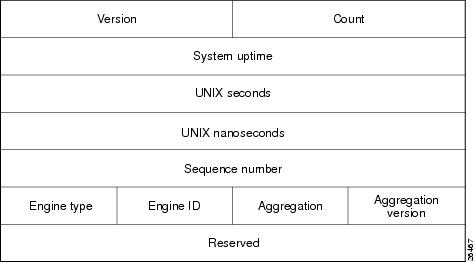
Table 10 lists definitions for terms used in the version 8 header.
Additional Information about NetFlow on the Cisco CMTS
For additional information about configuring NetFlow Accounting on Cisco CMTS, refer to the following documents on Cisco.com:
•
http://www.cisco.com/en/US/docs/net_mgmt/netflow_collection_engine/5.0/user/guide/overview.html
•
•
•
•
http://www.cisco.com/en/US/products/ps6601/prod_white_papers_list.html
•
http://www.cisco.com/en/US/products/ps6601/products_ios_protocol_group_home.html
PacketCable 1.0 With CALEA
Cisco IOS Release 12.3(9a)BC introduces DOCSIS 1.1 support for PacketCable 1.0 with Communications Assistance for Law Enforcement Act (CALEA) on the Cisco uBR10012 universal broadband router with the Cisco uBR10-MC5X20S/U Broadband Processing Engine (BPE).
PacketCable is a program initiative from Cablelabs and its associated vendors to establish a standard way of providing packet-based, real-time video and other multimedia traffic over hybrid fiber-coaxial (HFC) cable networks. The PacketCable specification is built upon the Data-over-Cable System Interface Specifications (DOCSIS) 1.1, but it extends the DOCSIS protocol with several other protocols for use over non-cable networks, such as the Internet and the public switched telephone network (PSTN).
This allows PacketCable to be an end-to-end solution for traffic that originates or terminates on a cable network, simplifying the task of providing multimedia services over an infrastructure composed of disparate networks and media types. It also provides an integrated approach to end-to-end call signaling, provisioning, quality of service (QoS), security, billing, and network management.
Cisco IOS Release 12.2(11)BC1 and later releases in the Cisco IOS 12.3 release train support the PacketCable 1.0 specifications and the CALEA intercept capabilities of the PacketCable 1.1 specifications.
For additional information about configuring PacketCable on the Cisco CMTS, refer to the following document on Cisco.com:
•
SFID Support for Multicast and Cable Interface Bundling
Cisco IOS Release 12.3(9a)BC removes the prior restriction in Caveat CSCea45592 that prevented the creation of DOCSIS 1.1 upstream packet classifiers and service flow IDs (SFIDs) when configuring multicast groups with bundled cable interfaces. Cable interface bundling now supports SFIDs on Multicast groups.
Note
Note
For additional configuration information, refer to the following document on Cisco.com:
•
http://www.cisco.com/en/US/docs/cable/cmts/feature/guide/ufg_bund.html
CBT 3.2 Spectrum Management Support with the Cisco uBR10-MC5X20S/U BPE
Cisco IOS Release 12.3(9a)BC introduces support for remote spectrum management for the Cisco uBR10012 router. Cisco uBR10012 spectrum management supports interoperability with these enhancements to the Cisco CMTS in Cisco IOS 12.3(9a)BC:
•
•
Additional supported spectrum management functions are available on the Cisco uBR10012 router. For a complete list, and the latest information about Spectrum Management on the Cisco uBR10012 router, refer to the following documents on Cisco.com:
•
http://www.cisco.com/en/US/docs/cable/cmts/feature/guide/ufg_spec.html
•
http://www.cisco.com/en/US/products/sw/netmgtsw/ps530/prod_release_notes_list.html
•
Subscriber Traffic Management (STM) Version 1.1
Cisco IOS Release 12.3(9a)BC introduces support for Subscriber Traffic Management (STM) through Version 1.1 on the Cisco uBR10012 universal broadband router. STM 1.1 supports DOCSIS 1.1-compliant cable modems.
The STM feature enables service providers to identify and control subscribers who exceed the maximum bandwidth allowed under their registered quality of service (QoS) profiles. STM is a simple bandwidth management tool which works as a low CPU alternative to Network-Based Application Recognition (NBAR) and access control lists (ACLs), however, using STM does not mean that NBAR and ACLs have to be turned off; STM can be applied along with NBAR and ACLs. STM 1.1 also works in conjunction with the Cisco Broadband Troubleshooter 3.2 to support additional network management and troubleshooting functions in the Cisco CMTS.
STM 1.1 extends earlier STM functions to monitor a subscriber's traffic on DOCSIS 1.1 primary service flows and supports these additional features:
•
•
•
•
For additional information about STM 1.1 and Cisco CBT 3.2, refer to the following document on Cisco.com:
•
http://www.cisco.com/en/US/docs/cable/cmts/feature/ubsubmon.html
•
http://www.cisco.com/en/US/products/sw/netmgtsw/ps530/prod_release_notes_list.html
Transparent LAN Service (TLS) on the Cisco uBR10012 Router with IEEE 802.1Q
Cisco IOS 12.3(9a)BC introduces support for the Transparent LAN Service over Cable feature on the Cisco 10012 router. This feature enhances existing Wide Area Network (WAN) support to provide more flexible Managed Access for multiple Internet service provider (ISP) support over a hybrid fiber-coaxial (HFC) cable network.
This feature allows service providers to create a Layer 2 tunnel by mapping an upstream service identifier (SID) to an IEEE 802.1Q Virtual Local Area Network (VLAN).
For additional information about configuring TLS on the Cisco uBR10012 CMTS, refer to the following document on Cisco.com:
•
http://www.cisco.com/en/US/docs/cable/cmts/feature/tls-cmts.html
Note
Usage Based Billing (SAMIS)
Cisco IOS Release 12.3(9a)BC introduces the Usage-Based Billing feature on the Cisco uBR10012 router. This feature provides subscriber account and billing information in the Subscriber Account Management Interface Specification (SAMIS) format. SAMIS is specified by the Data-over-Cable Service Interface Specifications (DOCSIS) Operations Support System Interface (OSSI) specification.
The CISCO-CABLE-METERING-MIB is also introduced with Cisco IOS Release 12.3(9a)BC in support of SAMIS.
For additional information about configuring and monitoring Usage-Based Billing (SAMIS) on the Cisco uBR10012 CMTS, refer to the following document on Cisco.com:
•
http://www.cisco.com/en/US/docs/cable/cmts/feature/ubrsamis.html
Virtual Interface and Frequency Stacking Support on the Cisco uBR10-MC5X20S/U BPE
Virtual interfaces (VI) and frequency stacking (FS) are two features that allow user-configurable MAC domains and multiple frequencies on one physical connector.
•
Cisco IOS Release 12.3(9a)BC introduces Virtual Interface Support for HCCP N+1 Redundancy with the Cisco uBR10-MC5X20S/U BPE.
•
Cisco IOS Release 12.3(9a)BC introduces support for frequency stacking on the Cisco uBR10012 router.
For additional information about configuring virtual interfaces and frequency stacking, refer to the following document on Cisco.com:
•
http://www.cisco.com/en/US/tech/tk86/tk804/technologies_white_paper09186a0080232b49.shtml
•
Virtual Interface Support for HCCP N+1 Redundancy
Cisco IOS Release 12.3(9a)BC introduces support for HCCP N+1 Redundancy for virtual interfaces configured on the Cisco uBR10012 universal broadband router using the Cisco uBR10-MC5X20S/U BPE.
HCCP N+1 Redundancy is an important step toward high availability on CMTS and telecommunications networks that use broadband media. HCCP N+1 Redundancy can help limit Customer Premises Equipment (CPE) downtime by enabling robust automatic switchover and recovery in the event that there is a localized disruption in service.
Beginning with Cisco IOS Release 12.2(15)BC2a, HCCP N+1 Redundancy adds synchronization between HCCP Working interface configurations and those inherited upon switchover to HCCP Protect interfaces. This makes the configuration of both easier and switchover times faster.
For additional information about configuring virtual interfaces in HCCP N+1 redundancy on the Cisco CMTS, refer to the following document on Cisco.com:
•
•
http://www.cisco.com/en/US/docs/cable/cmts/feature/guide/ufg_bund.html
MIBs
To locate and download MIBs for selected platforms, Cisco IOS releases, and feature sets, use Cisco MIB Locator found at the following URL:
http://tools.cisco.com/ITDIT/MIBS/servlet/index
If Cisco MIB Locator does not support the MIB information that you need, you can also obtain a list of supported MIBs and download MIBs from the Cisco MIBs page at the following URL:
http://www.cisco.com/public/sw-center/netmgmt/cmtk/mibs.shtml
To access Cisco MIB Locator, you must have an account on Cisco.com. If you have forgotten or lost your account information, send a blank e-mail to cco-locksmith@cisco.com. An automatic check will verify that your e-mail address is registered with Cisco.com. If the check is successful, account details with a new random password will be e-mailed to you. Qualified users can establish an account on Cisco.com by following the directions found at this URL:
http://tools.cisco.com/RPF/register/register.do
MIB Changes and Enhancements for Cisco IOS Release 12.3(21)BC:
The DOC-QOS-MIB enhancement in Cisco IOS Release 12.3(21)BC added new tables to support SNMP QoS MIB query time in a large scale system with much less CPU consumption. The overall performance is better in multiple SNMP query sessions on the six tables than a single session. However, this solution has the following restrictions:
•
•
•
Note
MIB Constraints and Notes
This MIB is supported only in Cisco IOS Release 12.2(4)BC1 through Release 12.2(11)BC3 to support DOCSIS 1.1 operations. The MIB is deprecated in later releases to conform with the DOCSIS 2.0 specifications.
.
Note
http://www.cisco.com/en/US/docs/cable/cmts/troubleshooting_batch9/cmtslbg.html
MIB Changes and Enhancements for Cisco IOS Release 12.3(17a)BC:
MIB enhancements in Cisco IOS Release 12.3(17a)BC provide enhanced management features that enable the Cisco uBR 7200 Series router and the Cisco uBR 10012 router to be managed through the Simple Network Management Protocol (SNMP). These enhanced management features allow you to:
•
•
•
•
•
For a complete list of changes to the Cisco CMTS Universal Broadband Router MIB Specifications Guide, go to the Revision History table:
http://www.cisco.com/en/US/docs/cable/cmts/mib/reference/guide/mibv5ubr.html
Important Notes
The following sections contain important notes about Cisco IOS Release 12.3(23)BC7 that apply to the Cisco uBR10012 universal broadband router universal broadband router.
How to Upgrade to Cisco IOS Release 12.3(21)BC
In circumstances in which non-volatile memory (NVRAM) becomes corrupted on the Cisco CMTS, configurations and feature behavior may become corrupted or lost, looping behavior in NVRAM may result, and additional measures to resolve corrupted NVRAM and lost configurations would be required.
This issue can be generated by upgrading to later Cisco IOS releases from prior Cisco IOS releases that do not contain resolution to a specific and known issue. This issue is not limited to Cisco IOS releases installed on the Cisco universal broadband routers.
Symptoms of Corrupted NVRAM
This issue is displayed with the following symptoms in the case of the Cisco CMTS:
•
–
This error message is displayed either when the router boots, or when you enter one of the following commands:
•
•
•
•
Conditions of Corrupted NVRAM
This symptom is observed under the following conditions:
•
–
–
–
–
When upgrading to Cisco IOS Release 12.3(21)BC, the following upgrade procedure prevents corruption to NVRAM, retains configurations made in earlier releases, and successfully installs Cisco IOS Release 12.3(21)BC images. This procedure is subject to the feature restrictions and prerequisites of Cisco IOS Release 12.3(21)BC, described in these release notes.
Prerequisites
Cisco strongly recommends that you back up your configuration files prior to performing this upgrade, or any upgrade.
SUMMARY STEPS
Perform these steps to upgrade to Cisco IOS 12.3(21)BC, after TFTP file transfer operations are complete.
1.
2.
3.
4.
5.
6.
DETAILED STEPS
New Command Information for Cisco IOS Release 12.3(21)BC
Cisco IOS Release 12.3(21)BC introduces support and modifications to the following commands for Cisco Cable Modem Termination System (CMTS) universal broadband routers.
Refer to the following sections for more information:
•
•
cable throttle-ranging
To enable faster cable modem registration times, use the cable throttle-ranging command in global configuration mode. To disable faster cable modem registration times, use the no form of this command.
cable throttle-ranging
no cable throttle-ranging
Syntax Description
This command has no arguments or keywords
Defaults
This command is disabled by default.
Command Modes
Global configuration
Command History
Usage Guidelines
The cable throttle-ranging command enables faster cable modem registration times on the CMTS.
Reload the Cisco CMTS with a Cisco IOS Release 12.3(21)BC image and configure the cable throttle-ranging command on the CMTS. Once the cable throttle-ranging has been configured, save the new configuration and reload the Cisco CMTS again. Faster cable modem registration times will now be enabled on the Cisco CMTS.
Note
Examples
The following example shows how to enable Fast CM registration feature on a Cisco CMTS:
Router# cable throttle-rangingRouter(config)#
Related Commands
There are no related commands for this command.
card
To preprovision a slot in the Cisco uBR10012 universal broadband router for a particular interface card, so that you can configure the interface without it being physically present in the slot, use the card command in global configuration mode. To remove the preprovisioning for a card, so that the physical slot reports being empty, use the no form of this command.
card {slot/subslot | slot/subslot/bay} card-type
no card {slot/subslot | slot/subslot/bay}
Syntax Description
slot/subslot
Identifies the chassis slot and subslot for the card. The following are the valid values:
•
•
slot/subslot/bay
Identifies the chassis slot and subslot for the Cisco Wideband SIP, and the bay number in the SIP where the Cisco Wideband SPA is located. The following are the valid values:
•
•
•
card-type
Specifies the type of card that should be used to preprovision the slot. See Table 12 for a list of the supported cards.
Note
Defaults
An empty card slot is not preprovisioned and cannot be configured or displayed.
Command Modes
Global configuration
Command History
Usage Guidelines
This command preprovisions a slot in the Cisco uBR10012 router to accept a particular line card, so that you can configure the interface without the card being physically present in the chassis. This command allows system administrators to plan for future configurations, without having to wait for the physical hardware to first arrive. When the line card does arrive, the installer can bring the card online by inserting the card into the chassis and connecting the necessary cables, without having to do any further configuration using the command-line interface.
The type of card must be appropriate for the slot being specified. Slots 1/1 and 2/1 are reserved for TCC+ utility cards. Slots 1/0 through 4/0 are reserved for network uplink line cards. Slot 5/0 through 8/1 are reserved for cable interface line cards. Slot 0/0 is reserved for the FastEthernet interface on the PRE1 module and cannot be specified in this command.
Table 12 lists the types of cards that are supported as card-types for the card command:

Tip
When a line card is inserted in the Cisco uBR10012 chassis, the router performs the following actions, depending on whether the card slot is preprovisioned for the card:
•
•
•
Tip
The no card version of the command removes the preprovisioning information from the given card slot. This also removes all configuration information for that card slot, as well as any information in the SNMP MIB database about the card and its card slot.
Examples
The following example shows a list of supported card types for Cisco IOS Release 12.2(8)BC1, and then shows that slot 8/0 is being preprovisioned for a Cisco uBR-LCP2-MC28C cable interface line card. The cable interface for slot 8/0 can then be configured.
Router# config tRouter(config)# card 5/0 ?1cable-mc16c create a uBR10000 line card with MC16C1cable-mc16e create a uBR10000 line card with MC16E1gigethernet-1 create a GE_1_PORT cardtype1oc12pos-1 create a OC12POS_1_PORT cardtype2cable-mc28bnc create a uBR10000 line card with MC28C, BNC connector2cable-mc28c create a uBR10000 line card with MC28C2oc12srp-sm-lr create a uBR10000 oc12 SRP card with SM LRRouter(config)# card 8/0 2cable-mc28cRouter(config)# int c8/0Router(config-if)#The following example shows the output from the show interface command for a preprovisioned cable interface. The second line of the output shows that the hardware is not present.
Router# show interface c8/0/0Cable8/0/0 is initializing, line protocol is downHardware is not presentHardware is UBR10000 CLC, address is 0001.6440.d160 (bia 0001.6440.d160)MTU 1500 bytes, BW 27000 Kbit, DLY 1000 usec,reliability 255/255, txload 1/255, rxload 1/255Encapsulation MCNS, loopback not setARP type: ARPA, ARP Timeout 04:00:00Last input never, output never, output hang neverLast clearing of "show interface" counters neverInput queue: 0/75/0/0 (size/max/drops/flushes); Total output drops: 0Queueing strategy: fifoOutput queue :0/40 (size/max)5 minute input rate 0 bits/sec, 0 packets/sec5 minute output rate 0 bits/sec, 0 packets/sec0 packets input, 0 bytes, 0 no bufferReceived 0 broadcasts, 0 runts, 0 giants, 0 throttles0 input errors, 0 CRC, 0 frame, 0 overrun, 0 ignored, 0 abort0 packets output, 0 bytes, 0 underruns0 output errors, 0 collisions, 0 interface resets0 output buffer failures, 0 output buffers swapped outRouter#The following examples show the two steps required to preprovision the Wideband SIP and Wideband SPA.
The Wideband SIP is preprovisioned with the card command and 2jacket-1 as the card type. For example:
Router# configure terminalRouter(config)# card 1/0 2jacket-1Router(config)#The Wideband SPA is preprovisioned with the card command and 24rfchannel-spa-1 as the card type. For example:
Router# configure terminalRouter(config)# card 1/0/0 24rfchannel-spa-1Router(config)#The preceding card command creates 12 wideband channels on the Wideband SPA.
Related Commands
show interface cable
Displays the current configuration and status of a cable interface.
clear cable modem reset
To remove one or more CMs from the Station Maintenance List and reset them, use the clear cable modem reset command in privileged EXEC mode.
clear cable modem {mac-addr | ip-addr | [cable slot/port] {all | oui string | reject} } reset
clear cable modem {mac-addr | ip-addr | [cable slot/subslot/port] {all | oui string | reject | wideband registered-traditional-docsis} } reset
Syntax Description
Defaults
No default behavior or values
Command Modes
Privileged EXEC
Command History
Usage Guidelines
This command instructs the Cisco CMTS to stop sending DOCSIS station maintenance messages to one or more CMs, which effectively terminates the link to those CMs. A CM responds to this by resetting itself. Depending on when the CM received the last station maintenance message, it can take up to 30 seconds before the CM detects the missing station maintenance messages and resets itself.
In some circumstances, the customer premises equipment (CPE) devices behind a CM stops receiving traffic after the CM is reset. This is because the CMTS still has the CPE device listed in its address tables, but the CM does not after being reset, so the traffic passes through the CMTS but is dropped by the CM. To resolve this situation, the CPE device should simply send some type of traffic to the CM, such as a ping packet. (You can also resolve this situation by using the clear arp-cache command on the Cisco CMTS router to clear the router's address table, but this is not recommended, because it temporarily interrupts all traffic on the router.)
Note
Caution
Tip
Examples
The following example shows how to reset the CM at 172.23.45.67:
Router# clear cable modem 172.23.45.67 resetRouter#The following example shows how to reset all CMs that have a OUI that has been defined as having the vendor name of Cisco using the cable modem vendor command:
Router# clear cable modem oui Cisco resetRouter#The following example shows how to reset all CMs that are currently in one of the reject states:
Router# clear cable modem reject resetRouter#The following example shows how to reset all wideband CMs that are registered as traditional DOCSIS modems.:
Router# clear cable modem wideband registered-traditional-docsis resetMAC Address IP Address I/F MAC Prim BG DSID MD-DS-SGState Sid ID0018.6852.825c 80.18.0.9 C5/0/0/U0 online 1 0 256 N/A0018.6852.8286 80.18.0.10 C5/0/0/U0 online 2 0 264 N/A0016.92fb.55be 80.18.0.7 C5/0/0/U0 online 3 0 288 N/A0016.92f0.9104 80.18.0.5 C5/0/0/U0 online 4 0 280 N/A0016.92fb.55c0 80.18.0.6 C5/0/0/U0 online 5 0 272 N/ARouter#
Related Commands
hw-module reload
To reload the software in and restart a Cisco 1-Gbps Wideband SPA, use the hw-module reload command in privileged EXEC mode.
hw-module bay slot/subslot/bay reload
Syntax Description
Defaults
No default behavior or values
Command Modes
Privileged EXEC
Command History
12.3(21)BC
This command was introduced for the Cisco uBR10012 universal broadband router.
Usage Guidelines
The hw-module reload command reloads the software in and restarts a Cisco 1-Gbps Wideband SPA.
Examples
The following example shows reloads the Cisco Wideband SPA in slot 1, subslot 0, bay 1.
Router# hw-module bay 1/0/1 reloadRouter#Related Commands
hw-module shutdown
To shut down a particular Performance Routing Engine (PRE1) module, line card, Wideband SIP or Wideband SPA, use the hw-module shutdown command in global configuration mode. To activate a specific PRE1, line card, Wideband SIP or Wideband SPA, use the no form of this command.
hw-module {main-cpu | pre {A|B} | sec-cpu | slot slot-number | subslot slot/subslot |
bay slot/subslot/bay} shutdown [unpowered]no hw-module {main-cpu | pre {A|B} | sec-cpu | slot slot-number | subslot slot/subslot |
bay slot/subslot/bay} shutdownSyntax Description
Defaults
No default behavior or values
Command Modes
Global configuration
Command History
12.2(4)XF
This command was introduced for the Cisco uBR10012 router.
12.3(21)BC
Support was added for the Cisco Wideband SIP and Cisco 1-Gbps Wideband SPA.
Usage Guidelines
The hw-module shutdown command shuts down a particular Performance Routing Engine (PRE1) module, line card, Wideband SIP or Wideband SPA. To activate a specific PRE1, line card, Wideband SIP, or Wideband SPA, use the no form of this command.
Caution
Examples
The following example shows the standby PRE1 module being shut down:
Router(config)# hw-module sec-cpu shutdownRouter(config)#The following example shows the active PRE1 module being shut down (which will trigger a switchover to the standby PRE1 module):
Router(config)# hw-module main-cpu shutdownRouter(config)#The following example shows the PRE1 module in PRE1 slot B being shut down:
Router(config)# hw-module pre B shutdownRouter(config)#
Note
The following example shows how to deactivate and verify deactivation for the Cisco Wideband SPA located in slot 1, subslot 0, bay 0. In the output of the show hw-module bay oir command, notice the "admin down" in the Operational Status field.
Router# configure terminalRouter(config)# hw-module bay 1/0/0 shutdown unpowered%SPAWBCMTS-4-SFP_MISSING: Wideband-Cable 1/0/0, 1000BASE-SX SFP missing from port 0%LINK-3-UPDOWN: Interface Wideband-Cable1/0/0:1, changed state to down%LINK-3-UPDOWN: Interface Wideband-Cable1/0/0:2, changed state to down%LINK-3-UPDOWN: Interface Wideband-Cable1/0/0:3, changed state to down%LINK-3-UPDOWN: Interface Wideband-Cable1/0/0:4, changed state to down%LINK-3-UPDOWN: Interface Wideband-Cable1/0/0:5, changed state to down%LINK-3-UPDOWN: Interface Wideband-Cable1/0/0:6, changed state to down%LINK-3-UPDOWN: Interface Wideband-Cable1/0/0:7, changed state to down%LINK-3-UPDOWN: Interface Wideband-Cable1/0/0:8, changed state to down%LINK-3-UPDOWN: Interface Wideband-Cable1/0/0:9, changed state to down%LINK-3-UPDOWN: Interface Wideband-Cable1/0/0:10, changed state to down%LINK-3-UPDOWN: Interface Wideband-Cable1/0/0:11, changed state to down...Router# show hw-module bay 1/0/0 oirModule Model Operational Status-------------- ------------------ -------------------------bay 1/0/0 SPA-24XDS-SFP admin downThe following example shows how to activate and verify activation for the Cisco Wideband SPA located in slot 1, subslot 0, bay 0. In the output of the show hw-module bay oir command, notice the "ok" in the Operational Status field.
Router# configure terminalRouter(config)# no hw-module bay 1/0/0 shutdown%SPAWBCMTS-4-SFP_OK: Wideband-Cable 1/0/0, 1000BASE-SX SFP inserted in port 0%SPAWBCMTS-4-SFP_LINK_OK: Wideband-Cable 1/0/0, port 0 link changed state to up%SNMP-5-LINK_UP: LinkUp:Interface Wideband-Cable1/0/0:0 changed state to up%LINK-3-UPDOWN: Interface Cable1/0/0:0, changed state to up%LINK-3-UPDOWN: Interface Wideband-Cable1/0/0:1, changed state to up%LINK-3-UPDOWN: Interface Wideband-Cable1/0/0:2, changed state to up%LINK-3-UPDOWN: Interface Wideband-Cable1/0/0:3, changed state to up%LINK-3-UPDOWN: Interface Wideband-Cable1/0/0:4, changed state to up%LINK-3-UPDOWN: Interface Wideband-Cable1/0/0:5, changed state to up%LINK-3-UPDOWN: Interface Wideband-Cable1/0/0:6, changed state to up%LINK-3-UPDOWN: Interface Wideband-Cable1/0/0:7, changed state to up%LINK-3-UPDOWN: Interface Wideband-Cable1/0/0:8, changed state to up%LINK-3-UPDOWN: Interface Wideband-Cable1/0/0:9, changed state to up%LINK-3-UPDOWN: Interface Wideband-Cable1/0/0:10, changed state to up%LINK-3-UPDOWN: Interface Wideband-Cable1/0/0:11, changed state to up%LINEPROTO-5-UPDOWN: Line protocol on Interface Wideband-Cable1/0/0:0, changed state to up...Router# show hw-module bay 1/0/0 oirModule Model Operational Status-------------- ------------------ -------------------------bay 1/0/0 SPA-24XDS-SFP okRelated Commands
show cable modem summary
To display a summary of CMs on one or more cable interfaces, use the show cable modem command in privileged EXEC mode.
show cable modem summary [total]
show cable modem summary interface1 [interface2] total
show cable modem summary interface1 [interface2] upstream port1 port2 total
show cable modem cable slot/port [upstream port] summary
show cable modem cable slot/subslot/port [upstream port] summary
Syntax Description
Command Modes
Privileged EXEC
Command History
Usage Guidelines
This command displays a summary of CMs for a single cable interface or upstream, or for a range of cable interfaces or upstreams. The following possible combinations are possible for this command:
•
•
•
•
•
Note
Examples
The following example shows typical output for the default form of the show cable modem summary command on a Cisco uBR7200 series router:
Router# show cable modem summaryInterface Total Active Registered DescriptionModems Modems ModemsCable3/0/U0 165 141 141 Line 32/1Cable3/0/U1 209 172 170 Line 32/2Cable3/0/U2 262 207 203 Line 32/3Cable3/0/U3 256 194 188 Line 32/4Cable5/0/U0 746 714 711 Line 41/1Cable6/0/U0 806 764 759 Line 42/2Router#
Note
The following example shows typical output for the show cable modem summary command with the total option on a Cisco uBR7200 series router:
Router# show cable modem summary totalInterface Total Active Registered DescriptionModems Modems ModemsCable5/0/U0 746 714 711 Node1Cable6/0/U1 806 764 759 Node3Total: 1552 1478 1470Router#The following example shows sample output for the show cable modem summary command with the total option for a Cisco uBR10012 router:
Router# show cable modem summary totalInterface Cable Modem DescriptionTotal Reg Unreg Offline Wideband initRC initD initIO initOC5/0/0/U0 84 84 0 0 84 0 0 0 0C5/0/0/U1 84 84 0 0 84 0 0 0 0C5/0/0/U2 83 83 0 0 83 0 0 0 0C5/0/0/U3 83 83 0 0 83 0 0 0 0<<output omitted>>Total: 8020 8020 0 0 8016 0 0 0 0Router#The following example shows sample output for the show cable modem summary total command for a range of interfaces on the Cisco uBR10012 router:
Router# show cable modem summary c5/1/1 c5/1/2 totalInterface Cable Modem DescriptionTotal Reg Unreg Offline Wideband initRC initD initIO initOC5/1/1/U0 84 84 0 0 84 0 0 0 0C5/1/1/U1 84 84 0 0 83 0 0 0 0C5/1/1/U2 83 83 0 0 83 0 0 0 0C5/1/1/U3 83 83 0 0 83 0 0 0 0C5/1/2/U0 84 84 0 0 84 0 0 0 0C5/1/2/U1 84 84 0 0 84 0 0 0 0C5/1/2/U2 83 83 0 0 83 0 0 0 0C5/1/2/U3 83 83 0 0 83 0 0 0 0Total: 668 668 0 0 667 0 0 0 0Router#The following example shows sample output for the show cable modem summary total command for a range of interfaces and upstreams on the Cisco uBR10012 router:
Router# show cable modem summary c5/1/1 c5/1/2 upstream 0 1 totalInterface Cable Modem DescriptionTotal Reg Unreg Offline Wideband initRC initD initIO initOC5/1/1/U0 84 84 0 0 84 0 0 0 0C5/1/1/U1 84 84 0 0 83 0 0 0 0C5/1/2/U0 84 84 0 0 84 0 0 0 0C5/1/2/U1 84 84 0 0 84 0 0 0 0Total: 336 336 0 0 335 0 0 0 0Router#
Note
Table 13 describes the fields shown in the show cable modem summary displays:
Note
Tip
Related Commands
show cable modem wideband
To display information for registered and unregistered wideband CMs, use the show cable modem wideband command in privileged EXEC mode.
show cable modem wideband [registered-traditional-docsis]
show cable modem [ip-address | mac-address | cable slot/subslot/port] wideband
Syntax Description
Command Modes
Privileged EXEC
Command History
12.3(21)BC
This command was introduced for the Cisco uBR10012 universal broadband router.
Usage Guidelines
This command displays information for a one or more wideband CMs. Optionally, the CMs for which to display information can be identified IP address, MAC address, or cable interface.
If a wideband-capable CM is not able to register as a wideband CM (for example, if no wideband channel is available), the CM attempts to register as a traditional DOCSIS modem. The registered-traditional-docsis keyword limits the set of wideband CMs for which to display information to wideband-capable CMs that are currently registered as DOCSIS 1.X or DOCSIS 2.0 modems.
Examples
The following example shows typical output for the default form of the show cable modem wideband command on a Cisco uBR10012 router:
Router# show cable modem widebandMAC Address IP Address I/F MAC Prim BG DSID MD-DS-SGState Sid ID0014.bfbe.3cc0 1.11.0.1 C5/0/1/U0 w-online(pt) 3 24 24 N/A0016.92f0.90d6 1.11.0.4 C5/0/1/U0 w-online(pt) 5 24 272 10014.bfbe.3cb8 1.11.0.2 C6/0/1/U0 w-online(pt) 3 36 36 N/A0016.92f0.90d8 1.11.0.3 C6/0/1/U0 w-online(pt) 5 36 274 1Router#Table 14 describes the fields that are shown in the show cable modem wideband display:
Table 15 shows the possible values for the MAC State field for a wideband CM modem that registers as a traditional DOCSIS modem:
Table 15 Descriptions for the MAC State Field (for Traditional DOCSIS Modems) 1
init(r1)
The CM sent initial ranging.
init(r2)
The CM is ranging. The CMTS received initial ranging from the CM and has sent RF power, timing offset, and frequency adjustments to the CM.
init(rc)
Ranging has completed.
Note
init(d)
The DHCP request was received, as DHCPDISCOVER. This also indicates that the first IP broadcast packet has been received from the CM.
init(dr)
The DHCP request has been sent to the cable modem.
init(i)
The cable modem has received the DHCPOFFER reply (DHCPACK) from the DHCP server that has assigned an IP address to the modem, but the modem has not yet replied with a DHCPREQUEST message requesting that particular IP address, nor has it sent an IP packet with that IP address.
Note
init(io)
The Cisco CMTS has seen the DHCP offer as sent to the cable modem from the DHCP server that has assigned an IP address to the modem.
init(o)
The CM has begun to download the option file (DOCSIS configuration file) using the Trivial File Transfer Protocol (TFTP), as specified in the DHCP response. If the CM remains in this state, it indicates that the download has failed.
init(t)
Time-of-day (TOD) exchange has started.
resetting
The CM is being reset and will shortly restart the registration process.
cc(r1)
The CM had registered and was online, but has received a Downstream Channel Change (DCC) or Upstream Channel Change (UCC) request message from the CMTS. The CM has begun moving to the new channel, and the CMTS has received the CM's initial ranging on the new downstream or upstream channel. At the MAC layer, the CM is considered offline because it is not yet passing traffic on the new channel, but this state does not trigger the flap-list counters.
cc(r2)
This state should normally follow cc(r1) and indicates that the CM has finished its initial ranging on the new channel, and is currently performing continuous ranging on the new channel. At the MAC layer, the CM is considered offline because it is not yet passing traffic on the new channel, but this state does not trigger the flap-list counters.
offline
The CM is considered offline (disconnected or powered down).
online
The CM has registered and is enabled to pass data on the network.
online(d)
The CM registered, but network access for CPE devices using this CM has been disabled through the DOCSIS configuration file. The CM does not forward traffic to or from the CPE devices, but the CMTS can continue to communicate with the CM using DOCSIS messages and IP traffic (such as SNMP commands).
Note
online(pkd)
The CM registered, but network access for CPE devices using this CM has been disabled through the DOCSIS configuration file. In addition, BPI is enabled and KEK is assigned.
Note
online(ptd)
The CM registered, but network access for CPE devices using this CM has been disabled through the DOCSIS configuration file. In addition, BPI is enabled and TEK is assigned. BPI encryption is now being performed.
Note
online(pk)
The CM registered, BPI is enabled and KEK is assigned.
online(pt)
The CM registered, BPI is enabled and TEK is assigned. BPI encryption is now being performed.
Note
Note
expire(pk)
The CM registered, BPI is enabled, KEK was assigned, but the current KEK expired before the CM could successfully renew a new KEK value.
expire(pkd)
The CM registered, but network access for CPE devices using this CM has been disabled through the DOCSIS configuration file. In addition, BPI is enabled, KEK was assigned, but the current KEK expired before the CM could successfully renew a new KEK value.
Note
expire(pt)
The CM registered, BPI is enabled, TEK was assigned, but the current TEK expired before the CM could successfully renew a new KEK value.
expire(ptd)
The CM registered, but network access for CPE devices using this CM has been disabled through the DOCSIS configuration file. In addition, BPI is enabled, TEK was assigned, but the current TEK expired before the CM could successfully renew a new KEK value.
Note
reject(m)
The CM attempted to register but registration was refused due to a bad Message Integrity Check (MIC) value. This also could indicate that the shared secret in the DOCSIS configuration file does not match the value configured on the CMTS with the cable shared-secret command.
In Cisco IOS Release 12.1(11b)EC1 and Cisco IOS Release 12.2(8)BC2 or later releases, this could also indicate that the cable tftp-enforce command has been used to require that a CM attempt a TFTP download of the DOCSIS configuration file before registering, but the CM did not do so.
reject(c)
The CM attempted to register, but registration was refused due to a a number of possible errors:
•
•
•
•
•
reject(pk)
KEK key assignment is rejected, BPI encryption has not been established.
reject(pkd)
The CM registered, but network access for CPE devices using this CM has been disabled through the DOCSIS configuration file. In addition, BPI encryption was not established because KEK key assignment was rejected.
Note
reject(pt)
TEK key assignment is rejected, BPI encryption has not been established.
reject(ptd)
The CM registered, but network access for CPE devices using this CM has been disabled through the DOCSIS configuration file. In addition, BPI encryption was not established because TEK key assignment was rejected.
Note
reject(ts)
The CM attempted to register, but registration failed because the TFTP server timestamp in the CM registration request did not match the timestamp maintained by the CMTS. This might indicate that the CM attempted to register by replaying an old DOCSIS configuration file used during a prior registration attempt.
reject(ip)
The CM attempted to register, but registration failed because the IP address in the CM request did not match the IP address that the TFTP server recorded when it sent the DOCSIS configuration file to the CM. IP spoofing could be occurring.
reject(na)
The CM attempted to register, but registration failed because the CM did not send a Registration-Acknowledgement (REG-ACK) message in reply to the Registration-Response (REG-RSP) message sent by the CMTS. A Registration-NonAcknowledgement (REG-NACK) is assumed.
1 The CM MAC state field can also be retrieved using SNMP by getting the value of the cdxCmtsCmStatusValue object in the CISCO-DOCS-EXT-MIB.
Tip
Table 16 shows the possible values for the MAC state field for a wideband-capable CM that registers as a wideband modem:
Related Commands
show interface wideband-cable
To display the current configuration and status for a wideband channel, use the show interface wideband-cable command in privileged EXEC mode.
show interface wideband-cable slot/subslot/bay:wideband_channel [options]
Syntax Description
Note
Command Modes
Privileged EXEC
Command History
12.3(21)BC
This command was introduced on the uBR10012 universal broadband router.
Examples
The following is a sample output for the show interface wideband-cable command:Router# show interface wideband-cable 1/0/0:1Wideband-Cable1/0/0:1 is up, line protocol is upHardware is Wideband CMTS Cable interface, address is 0012.001a.8897 (bia 0012.001a.8897)MTU 1500 bytes, BW 74730 Kbit, DLY 1000 usec,reliability 255/255, txload 1/255, rxload 1/255Encapsulation MCNS, loopback not setKeepalive set (10 sec)ARP type: ARPA, ARP Timeout 04:00:00Last input never, output 00:00:09, output hang neverLast clearing of "show interface" counters neverInput queue: 0/75/0/0 (size/max/drops/flushes); Total output drops: 0Queueing strategy: fifoOutput queue: 0/40 (size/max)30 second input rate 0 bits/sec, 0 packets/sec30 second output rate 0 bits/sec, 0 packets/sec0 packets input, 0 bytes, 0 no bufferReceived 0 broadcasts, 0 runts, 0 giants, 0 throttles0 input errors, 0 CRC, 0 frame, 0 overrun, 0 ignored, 0 abort24224 packets output, 1222002 bytes, 0 underruns0 output errors, 0 collisions, 0 interface resets0 output buffer failures, 0 output buffers swapped outRouter#Table 17 describes the fields shown in the show interface wideband-cable display.
Tip
Related Commands
Restrictions for Cisco IOS Release 12.3(17a)BC
When upgrading the CiscouBR10012 Performance Routing Engine 1 (PRE1) modules to Cisco uBR10012 PRE2 modules, you must reconfigure the cable intercept feature when enabled on a slave interface. For additional information about the Cable Intercept feature, cable interface bundling, or virtual master interfaces in cable interface bundling, refer to the following documents on Cisco.com:
–
http://www.cisco.com/en/US/docs/cable/cmts/feature/guide/ufg_bund.html
–
http://www.cisco.com/en/US/docs/cable/cmts/feature/guide/ufg_cmon.html
–
http://www.cisco.com/en/US/docs/ios/cable/command/reference/cbl_book.html
New Command Information for Cisco IOS Release 12.3(13a)BC3
Cisco IOS Release 12.3(13a)BC3 introduces support for the debug cable classifier command, which displays debugging information supporting DOCSIS packet classifiers.
debug cable classifiers
To display debugging messages for DOCSIS packet classifiers, use the debug cable classifiers command in privileged EXEC mode. To stop the display of debugging messages, use the no form of this command.
debug cable classifiers
no debug cable classifiers
Syntax Description
No additional keywords or syntax components are required.
Command Modes
Privileged EXEC mode
Defaults
DOCSIS packet classifier debugging is disabled by default.
Command History
12.3(13a)BC3
This command was introduced on the Cisco uBR10012 and Cisco uBR7246VXR universal broadband routers.
Usage Guidelines
The debug cable classifiers command provides detailed information about the allocation, removal, activation and deactivation of packet classifiers. Generally, classifiers are used to identify IP packets by source port, destination port, or type of service. Classifiers are associated with service flows. For example, packet classifiers are dynamically created in most Voice over IP (VoIP) deployments and this debug command can be used to troubleshoot issues related to these classifiers as VOIP calls are created and torn down.
Because this command can produce a large volume of debug information, use this command only when you have also enabled debugging for a particular MAC address, set of MAC addresses, or a MAC address mask, using the debug cable mac-address command.
For additional debug command information, refer to the following document on Cisco.com:
•
http://www.cisco.com/en/US/docs/ios/cable/command/reference/cbl_book.html
Examples
The following example enables classifier debugging for a single MAC address:
Router# debug cable mac-address 000a.73fa.dbaaRouter# debug cable classifiersCMTS Packet Classifiers debugging is onThe following enables classifier debugging for all MAC addresses with Organizational Unique Identifier (OUI) OUI 0013.11:
Router# debug cable mac-addr 0013.1100.0000 ffff.ff00.0000Routerv# debug cable classifiersCMTS Packet Classifiers debugging is onThe following example illustrates sample output of the debug cable classifiers command for the given MAC addresses:
Feb  7 18:43:50.181: CFR cmts_deactivate_us_srv_flow_act_cfrs 000a.73fa.dbaa sid 1 sfid 3
st 2 dir 0 prov 1 adm 1 act 1
Feb 7 18:43:50.181: CFR cmts_remove_cm_srv_flow_cfrs 000a.73fa.dbaa sid 1 sfid 3 st 2 dir 0 prov 1 adm 0 act 0Feb 7 18:43:50.181: CFR cmts_deactivate_ds_srv_flow_act_cfrs 000a.73fa.dbaa sid 0 sfid 4 st 2 dir 1 prov 2 adm 2 act 2Feb 7 18:43:50.181: CFR cmts_remove_cm_srv_flow_cfrs 000a.73fa.dbaa sid 0 sfid 4 st 2 dir 1 prov 2 adm 0 act 0Feb 7 18:43:50.181: CFR cmts_deactivate_us_srv_flow_act_cfrs 000a.73fa.dbaa sid 1 sfid 3 st 2 dir 0 prov 3 adm 0 act 0Feb 7 18:43:50.181: CFR cmts_deactivate_us_srv_flow_act_cfrs 000a.73fa.dbaa sid 1 sfid 3 st 1 dir 0 prov 3 adm 3 act 0Feb 7 18:43:50.181: CFR cmts_activate_us_srv_flow_act_cfrs 000a.73fa.dbaa sid 1 sfid 3 st 2 dir 0 prov 3 adm 3 act 3Feb 7 18:43:50.181: CFR cmts_deactivate_ds_srv_flow_act_cfrs 000a.73fa.dbaa sid 0 sfid 4 st 2 dir 1 prov 4 adm 0 act 0Feb 7 18:43:50.181: CFR cmts_deactivate_ds_srv_flow_act_cfrs 000a.73fa.dbaa sid 0 sfid 4 st 1 dir 1 prov 4 adm 4 act 0Feb 7 18:43:50.181: CFR cmts_activate_ds_srv_flow_act_cfrs 000a.73fa.dbaa sid 0 sfid 4 st 2 dir 1 prov 4 adm 4 act 4Feb 7 18:43:50.181: CFR cmts_set_cfr_params 000a.73fa.dbaa cfrid 1 pri 0 ord 0 dir 0 st 2 phsi 0Feb 7 18:43:50.181: CFR cmts_activate_cfr 000a.73fa.dbaa cfrid 1 pri 1 ord 0 dir 0 st 2Feb 7 18:43:50.181: CFR cmts_add_pkt_cfr 000a.73fa.dbaa cfrid 1 pri 1 ord 0 dir 0 st 1 phsi 0Feb 7 18:43:50.181: CFR cmts_handle_cfr_parsed_data CFR_ADD 000a.73fa.dbaa sfid 0 action 0 dir 0 type 0 cfrid 0 pri 1 ord 0 dir 0 st 1 phsi 0Feb 7 18:43:50.181: CFR cmts_set_cfr_params 000a.73fa.dbaa cfrid 2 pri 0 ord 0 dir 1 st 2 phsi 0Feb 7 18:43:50.181: CFR cmts_activate_cfr 000a.73fa.dbaa cfrid 2 pri 1 ord 0 dir 1 st 2Feb 7 18:43:50.181: CFR cmts_add_pkt_cfr 000a.73fa.dbaa cfrid 2 pri 1 ord 1 dir 1 st 1 phsi 0Feb 7 18:43:50.181: CFR cmts_handle_cfr_parsed_data CFR_ADD 000a.73fa.dbaa sfid 0 action 0 dir 1 typRelated Commands
debug cable dynsrv
Displays information about DOCSIS 1.1 dynamic service flow messages.
debug cable qos
Activates quality-of-service (QoS) debugging.
New Command Information for Cisco IOS Release 12.3(13a)BC2
Cisco IOS Release 12.3(13a)BC2 introduces support for the cable service flow activity-timeout command, which enables the configuration of dynamic service flow timeout settings apart from a PacketCable environment.
cable service flow activity-timeout
To configure the activity timeout for dynamic cable service flows in DOCSIS 1.1 environments, where PacketCable is inactive, use the cable service flow activity-timeout command in global configuration mode. To remove the activity timer once configured, use the no form of this command.
cable service flow activity-timeout n
no cable service flow activity-timeout [<n>]
Syntax Description
n
The timeout length in seconds. Valid range is 0 - 65535 seconds. Setting this value to 0 configures the service flow to never timeout.
Defaults
The default timeout length for a DOCSIS 1.0+ cable service flow is 300 seconds (five minutes).
Command Modes
Global configuration
Command History
12.3(13a)BC
This command was introduced to support DOCSIS 1.1 service flow operation in non-Packet-Cable environments.
Usage Guidelines
Dynamic service flows in DOCSIS 1.0+ are created with a default activity timeout of 300 seconds. This enables the deletion of idle service flows after five minutes. This new command enables such functions within DOCSIS 1.1 environments with a wide range of timeout length options.
In DOCSIS 1.1, the default inactivity timeout is often set by the application that triggers the creation of dynamic service flows. PacketCable frequently performs this function when supported on the Cisco CMTS. However, this new command configures inactivity timeout where PacketCable is not active on the Cisco CMTS.
Note
Apart from PacketCable, this command enables the cable modem to control the setup of the dynamic service flows, and to remove inactive service flows. During the creation of service flows, all Upstream and Downstream flows in the request are checked to see if the configured activity timeout needs to be applied.
Examples
The following example in global configuration mode configures the cable modems connected to the Cisco CMTS to use activity timeout of zero, which means that related service flows do not timeout in a non-PacketCable environment:
Router(config)# cable service flow activity-timeout 0Related Commands
Restrictions for Cisco IOS Release 12.3(13a)BC
The following restrictions apply to Cisco IOS Release 12.3(13aq)BC:
•
•
–
–
http://www.cisco.com/en/US/docs/cable/cmts/feature/guide/ufg_cmon.html
–
http://www.cisco.com/en/US/docs/ios/cable/command/reference/cbl_book.html
Restrictions for Cisco IOS Release 12.3(9a)BC
The following restrictions apply to Cisco IOS Release 12.3(9a)BC:
•
•
–
http://www.cisco.com/en/US/docs/cable/cmts/feature/guide/ufg_cmon.html
–
http://www.cisco.com/en/US/docs/ios/cable/command/reference/cbl_book.html
New and Changed Command Reference for Cisco IOS Release 12.3(9a)BC
Cisco IOS Release 12.3(9a)BC introduces or enhances the following Cisco IOS commands for the Cisco uBR10012 router:
cable logging layer2events
To save selected (low priority) DOCSIS events that are specified in CMTS MIB Registry to the cable logging buffer (instead of to the general logging buffer), use the cable logging layer2events command in global configuration mode. To disable the logging of DOCSIS events to the cable logging buffer, use the no form of this command.
cable logging layer2events
no cable logging layer2events
Syntax Description
This command has no additional arguments or keywords.
Defaults
DOCSIS events are saved to the general logging buffer on the Cisco CMTS by default.
Command Modes
Global configuration mode
Command History
12.3(9a)BC
This command was introduced on the Cisco uBR10012 and Cisco uBR7246VXR universal broadband routers.
Usage Guidelines
Use the show cable logging command to check whether the logging feature is enabled and the status of the logging buffer.
Examples
The following example shows how to clear the log buffer that contains a bad IP source address error messages:
Router# show cable logging summaryCable logging: BADIPSOURCE EnabledTotal buffer size (bytes): 1000000Used buffer size (bytes) : 36968Logged messages : 231Router# clear cable logging badipsourceRouter# show cable logging summaryCable logging: BADIPSOURCE EnabledTotal buffer size (bytes): 1000000Used buffer size (bytes) : 0Logged messages : 0Related Commands
For additional information about logging events on the Cisco CMTS, refer to the following document on Cisco.com:
•
http://www.cisco.com/en/US/docs/ios/cable/command/reference/cbl_book.html
cable source-verify
To enable verification of IP addresses or service IDs (SIDs) for CMs and CPE devices on the upstream, use the cable source-verify command in global configuration, cable interface configuration or subinterface configuration modes. To disable verification, use the no form of this command.
Cable Interface and Subinterface Configuration Modes
cable source-verify [dhcp | leasetimer value | leasequery-filter upstream query-num interval]
no cable source-verify
Global Configuration Mode
cable source-verify leasequery-filter downstream query-num interval
no cable source-verify
Syntax Description
Defaults
Disabled. When the dhcp option is specified, the leasetimer option is set by default to 60 minutes.
Command Modes
Global configuration, Cable interface configuration or subinterface configuration
Note
Command History
For additional information about this and other commands, refer to the following document on Cisco.com:
•
http://www.cisco.com/en/US/docs/ios/cable/command/reference/cbl_book.html
cable submgmt default
To enable the Cisco CMTS Static CPE Override feature on the Cisco CMTS, use the cable submgmt default command in global configuration mode. This command enables field technicians to add a temporary CPE device behind the subscriber's cable modem. The temporary CPE device shares the same SID settings as the original CPE device, even though the temporary CPE device has a different MAC address. The original CPE device automatically changes from dhcp cpe to static cpe in the CMTS host routing tables, and the CPE device continues to receive service with the same SID. To disable Cisco CMTS Static CPE Override on the Cisco CMTS, use the no form of this command. This automatically updates the routing tables and enables the MAC address from the technician's laptop for a future field service connection at a different location.
cable submgmt default {active | filter-group {cm | cpe} | learnable | max-cpe}
no cable submgmt default
Syntax Description
Defaults
This command is disabled by default.
Command Modes
Global configuration mode
Command History
12.3(9a)BC
This feature was introduced on Cisco uBR10012 and Cisco uBR7200 series universal broadband routers.
Usage Guidelines
Prior to using this command, the first (existing) DHCP CPE device maintains its DHCP dynamic MAC address behind the cable modem. The SID is assigned to this IP address.
However, by enabling Static CPE override, you gain the following states and options on two CPE devices behind the cable modem.
•
•
Note
Examples
The following example enables Cisco CMTS Static CPE Override in the field, enabling more or more additional CPE devices to be added behind a subscriber's cable modem:
Router(config)# cable submgmt default activeThe following example configures the Cisco CMTS to accept a temporary CPE device, which inherits and filters by the subscriber's default downstream cable modem group:
Router(config)# cable submgmt default filter-group cm downstreamThe following example configures the Cisco CMTS to accept a temporary CPE device, and to update the temporary CPE device with the current routing table from the Cisco CMTS:
Router(config)# cable submgmt default learnableThe following example configures the Cisco CMTS to accept a maximum of five temporary CPE devices behind a subscriber's cable modem:
Router(config)# cable submgmt default max-cpe 5Related Commands
show cable host
Displays the CPE devices (hosts) residing behind a specified cable modem (MAC address).
show cable tech-support
Cisco IOS Release 12.3(9a)BC introduces changes to the output of the show cable tech-support command. This change allows users with large numbers of online cable modems to collect the necessary information without consuming the console session for a long period of time.
To display general information about the router when reporting a problem, use the show cable tech-support command in privileged EXEC mode.
show cable tech-support [cable slot/port | cable slot/subslot/port]
Syntax Description
Syntax Description
This command has no arguments or keywords.
Defaults
No default behavior or values
Command Modes
Privileged EXEC
Command History
Examples
The following example illustrates the cable modem and interface information for the Cisco uBR10012 router on which Cisco IOS Release 12.3(9a)BC is installed.
Router# show cable tech-support----------------------------------- Slot 8/1 ----------------------------------------------------- show cable modem Cable8/1/0 ------------------MAC Address IP Address I/F MAC Prim RxPwr Timing Num BPIState Sid (dB) Offset CPE Enb------------------ show cable modem Cable8/1/0 connectivity ------------------Prim 1st time Times %online Online time Offline timeSid online Online min avg max min avg max------------------ show interface Cable8/1/0 sid ------------------Sid Prim MAC Address IP Address Type Age Admin Sched SfidState Type------------------ show interface Cable8/1/0 sid counter ------------------Sid Req-polls BW-reqs Grants Packets Frag Concatpktsissued received issued received complete received------------------ show interface Cable8/1/0 sid association ------------------Sid Prim Online IP Address MAC Address Interface VRF Name------------------ show interface Cable8/1/0 modem 0 ------------------SID Priv bits Type State IP address method MAC address------------------ show cable modem Cable8/1/1 ------------------MAC Address IP Address I/F MAC Prim RxPwr Timing Num BPIState Sid (dB) Offset CPE Enb------------------ show cable modem Cable8/1/1 connectivity ------------------Prim 1st time Times %online Online time Offline timeSid online Online min avg max min avg max------------------ show interface Cable8/1/1 sid ------------------Sid Prim MAC Address IP Address Type Age Admin Sched SfidState Type------------------ show interface Cable8/1/1 sid counter ------------------Sid Req-polls BW-reqs Grants Packets Frag Concatpktsissued received issued received complete received------------------ show interface Cable8/1/1 sid association ------------------Sid Prim Online IP Address MAC Address Interface VRF Name------------------ show interface Cable8/1/1 modem 0 ------------------SID Priv bits Type State IP address method MAC addressFor additional information about this and other commands, refer to the following document on Cisco.com:
•
http://www.cisco.com/en/US/docs/ios/cable/command/reference/cbl_book.html
show controllers cable
Cisco IOS Release 12.3(9a)BC adds the tech-support keyword to the show controllers cable command. This change allows users with large numbers of online cable modems to collect the necessary line card information without consuming the console session for a long period of time.
Additional and related improvements are also available for the show tech-support command.
To display information about the interface controllers for a cable interface on the Cisco CMTS router, use the show controllers cable command in user EXEC or privileged EXEC mode.
show controllers cable {slot/port | slot/subslot/port} [downstream | upstream [port] | [mem-stat] [memory] [proc-cpu] [tech-support] ]
Syntax Description
slot/port
Identifies the cable interface and downstream port on the Cisco uBR7100 series and Cisco uBR7200 series routers.
On the Cisco uBR7100 series router, the only valid value is 1/0. On the Cisco uBR7200 series router, slot can range from 3 to 6, and port can be 0 or 1, depending on the cable interface.
slot/subslot/port
Identifies the cable interface on the Cisco uBR10012 router. The following are the valid values:
•
•
•
downstream
(Optional) Displays downstream interface status.
upstream
(Optional) Displays upstream interface status.
port
(Optional) Specifies the desired upstream port. Valid values start with 0 for the first upstream port on the cable interface line card.
mem-stat
(Optional) Displays the output from the show memory statistics command to display a summary of memory statistics for a Broadband Processing Engine (BPE) cable interface line card.
memory
(Optional) Displays the output from the show memory command to display a summary of memory statistics, including the memory as it is allocated per process, for a Broadband Processing Engine (BPE) cable interface line card.
proc-cpu
(Optional) Displays the output from the show processes cpu command to display the processor status for a Broadband Processing Engine (BPE) cable interface line card.
tech-support
(Optional, privileged EXEC mode only) Displays the output from the show cable tech-support command for a Broadband Processing Engine (BPE) cable interface line card.
Command Modes
User EXEC, Privileged EXEC
Command History
Usage Guidelines
The mem-stat, memory, and proc-cpu keywords execute the related command on the processor that runs on added to obtain the relevant information from the onboard processor on Broadband Processing Engine (BPE) cable interface line cards, such as the Cisco uBR-MC16U/X, Cisco uBR-MC28U/X, and Cisco uBR10-MC5X20S/U cards. This allows you to obtain information that is specific for that particular cable interface card, as opposed to having to run these commands on the entire router.
Note
Examples
The following is sample output for the downstream connection for cable interface 8/1/0 on a Cisco uBR10012 router:
Router# show controllers c8/1/0 downstreamCable8/1/0 Downstream is upFrequency not set, Channel Width 6 MHz, 64-QAM, Symbol Rate 5.056941 MspsFEC ITU-T J.83 Annex B, R/S Interleave I=32, J=4Downstream channel ID: 0Dynamic Services Stats:DSA: 0 REQs 0 RSPs 0 ACKs0 Successful DSAs 0 DSA FailuresDSC: 0 REQs 0 RSPs 0 ACKs0 Successful DSCs 0 DSC FailuresDSD: 0 REQs 0 RSPs0 Successful DSDs 0 DSD FailuresDCC: 0 REQs 0 RSPs 0 ACKs0 Successful DCCs 0 DCC FailuresTable 18 describes the fields displayed by the show controllers cable downstream command.
Examples
The following example illustrates the information from the show controllers cable command for slot/subslot/port 8/1/0 on a Cisco uBR10012 router on which Cisco IOS Release 12.3(9a)BC is installed.
Router# show controllers c8/1/0Interface Cable8/1/0Hardware is MC28C(F-connector)BCM3210 revision=0x56B2idb 0x61329EB0 MAC regs 0x3E104000 PLX regs 0x3E000000rx ring entries 1024 tx ring entries 128 MAP tx ring entries 128Rx ring 0xC1AD080 shadow 0x613AAB38 head 0Tx ring 0xC1AF0C0 shadow 0x613ABBA8 head 34 tail 34 count 0MAP Tx ring 0xC1AF500 shadow 0x613AC018 head 52 tail 52 count 0Timestamp is from TCCplus cardthrottled 0 enabled 0 disabled 0Rx: spurious 0 framing_err 0 hcs_err 0 no_buffer 0 short_pkt 0no_enqueue 0 no_enp 0 miss_count 0 latency 0invalid_sid 0 invalid_mac 0 bad_ext_hdr_pdu 0 concat 0 bad-concat 0Tx: full 0 drop 0 stuck 0 latency 20MTx: full 0 drop 0 stuck 0 latency 10Slots 0 NoUWCollNoEngy 0 FECorHCS 1 HCS 1Req 3842362657 ReqColl 0 ReqNoise 0 ReqNoEnergy 3842362657ReqData 32 ReqDataColl 0 ReqDataNoise 0 ReqDataNoEnergy 32Rng 0 RngColl 0 RngNoise 0FECBlks 1 UnCorFECBlks 1 CorFECBlks 0MAP FIFO overflow 0, Rx FIFO overflow 0, No rx buf 0DS FIFO overflow 0, US FIFO overflow 0, US stuck 0Bandwidth Requests= 0x0--More--The following example illustrates memory statistics for the specified slot/subslot/port on the Cisco uBR10012 router:
Router# show controllers c8/1/0 mem-statHead Total(b) Used(b) Free(b) Lowest(b) Largest(b)Processor 60F3FB40 185337024 8644376 176692648 176557288 176638828I/O C000000 67108864 6679384 60429480 60429480 60405696The following example illustrates upstream information for the specified slot/subslot/port on the Cisco uBR10012 router:
Router# show controllers c8/1/0 upstreamCable8/1/0 Upstream 0 is upFrequency 25.008 MHz, Channel Width 1.600 MHz, QPSK Symbol Rate 1.280 MspsSpectrum Group is overriddenSNR - Unknown - no modems online.Nominal Input Power Level 0 dBmV, Tx Timing Offset 0Ranging Backoff automatic (Start 0, End 3)Ranging Insertion Interval automatic (60 ms)Tx Backoff Start 3, Tx Backoff End 5Modulation Profile Group 1Concatenation is enabledFragmentation is enabledpart_id=0x3137, rev_id=0x03, rev2_id=0xFFnb_agc_thr=0x0000, nb_agc_nom=0x0000Range Load Reg Size=0x58Request Load Reg Size=0x0EMinislot Size in number of Timebase Ticks is = 4Minislot Size in Symbols = 32Bandwidth Requests = 0x0Piggyback Requests = 0x0Invalid BW Requests= 0x0Minislots Requested= 0x0Minislots Granted = 0x0Minislot Size in Bytes = 8Map Advance (Dynamic) : 2180 usecsUCD Count = 320676DES Ctrl Reg#0 = C000C043, Reg#1 = 0The following example illustrates CPU processes for the specified slot/subslot/port on the Cisco uBR10012 router:
Router# show controllers c8/1/0 proc-cpuCPU utilization for five seconds: 1%/1%; one minute: 1%; five minutes: 1%PID Runtime(ms) Invoked uSecs 5Sec 1Min 5Min TTY Process1 4 1 4000 0.00% 0.00% 0.00% 0 Chunk Manager2 0 128036 0 0.00% 0.00% 0.00% 0 Load Meter3 248 395 627 0.00% 0.00% 0.00% 0 CR10K IPC MSG Pr4 428012 384113 1114 0.07% 0.07% 0.07% 0 CR10K NonBlk Xmt5 43392 65009 667 0.00% 0.00% 0.00% 0 Check heaps6 8 561 14 0.00% 0.00% 0.00% 0 Pool Manager7 0 1 0 0.00% 0.00% 0.00% 0 AAA_SERVER_DEADT8 0 2 0 0.00% 0.00% 0.00% 0 Timers9 0 2 0 0.00% 0.00% 0.00% 0 AAA high-capacit10 0 10680 0 0.00% 0.00% 0.00% 0 ARP Input11 0 1 0 0.00% 0.00% 0.00% 0 Entity MIB API12 0 2 0 0.00% 0.00% 0.00% 0 Serial BackgrounThe following example illustrates memory processor information for the specified slot/subslot/port on the Cisco uBR10012 router:
Router# show controllers c8/1/0 memoryHead Total(b) Used(b) Free(b) Lowest(b) Largest(b)Processor 60F3FB40 185337024 8644376 176692648 176557288 176638828I/O C000000 67108864 6679384 60429480 60429480 60405696Processor memoryAddress Bytes Prev Next Ref PrevF NextF Alloc PC what60F3FB40 0000020004 00000000 60F4498C 001 -------- -------- 60113308 Managed Chunk Queue Elements60F4498C 0000001504 60F3FB40 60F44F94 001 -------- -------- 60126F88 List Elements60F44F94 0000005004 60F4498C 60F46348 001 -------- -------- 60126FCC List Headers60F46348 0000000048 60F44F94 60F463A0 001 -------- -------- 6055D4E4 *Init*60F463A0 0000000028 60F46348 60F463E4 001 -------- -------- 604C12B4 *Init*60F463E4 0000000048 60F463A0 60F4643C 001 -------- -------- 6055D4E4 *Init*60F4643C 0000000200 60F463E4 60F4652C 001 -------- -------- 6014BE28 *Init*60F4652C 0000004260 60F4643C 60F475F8 001 -------- -------- 60065A2C TTY data60F475F8 0000002004 60F4652C 60F47DF4 001 -------- -------- 60069164 TTY Input BufThe following example illustrates the first information for the tech-support option for the specified slot/subslot/port on the Cisco uBR10012 router:
Router# show controllers c8/1/0 tech-support------------------ show version ------------------Cisco Internetwork Operating System SoftwareIOS (tm) 7200 Software (UBR10KCLC-LC-M), Experimental Version 12.3(20040708:144155) [bguckel-geo_cable-l2 102]Copyright (c) 1986-2004 by cisco Systems, Inc.Compiled Mon 12-Jul-04 11:28 by bguckelImage text-base: 0x60008EB8, data-base: 0x60CB0000ROM: System Bootstrap, Version 12.2(20011031:221132) [maheshj-cr10k-rommon 15],DEVELOPMENT SOFTWAREBOOTLDR: 7200 Software (UBR10KCLC-LC-M), Experimental Version 12.2(20011107:233103) [janez-v122_2_xf_throttle.Nov5A 101]clc_8_1 uptime is 1 week, 9 hours, 54 minutesSystem returned to ROM by power-onSystem restarted at 08:59:44 UTC Wed Jul 21 2004Running default softwarecisco uBR10K CLC (NPE-CLC) processor (revision A) with 196608K/65536K bytes of memory.Processor board IDR7000 CPU at 262MHz, Implementation 39, Rev 2.1, 256KB L2 Cache6 slot midplane, Version 1.0For additional information about this and other commands, refer to the following document on Cisco.com:
•
http://www.cisco.com/en/US/docs/ios/cable/command/reference/cbl_book.html
show tech-support
Cisco IOS Release 12.3(9a)BC shortens the output of the show tech-support command on the Cisco uBR10012 and the Cisco uBR7246VXR routers. This change allows users with large numbers of online cable modems to collect information without consuming the console session for a long period of time.
To display general information about the Cisco CMTS router when reporting a problem to Cisco technical support, use the show tech-support command in privileged EXEC mode.
show tech-support [page] [password] [cef | ipc | ipmulticast | isis | mpls | ospf | rsvp]
Note
Note
Syntax Description
For additional information about this and other commands, refer to the following document on Cisco.com (updated through Cisco IOS Release 12.3(9a)BC):
•
http://www.cisco.com/en/US/docs/ios/cable/command/reference/cbl_book.html
Caveats for Cisco IOS Release 12.3 BC
Caveats describe unexpected behavior in Cisco IOS software releases. Severity 1 caveats are the most serious caveats; severity 2 caveats are less serious. Severity 3 caveats are moderate caveats, and only selected severity 3 caveats are included in the caveats document.
Cisco IOS Release 12.3 mainline is the parent release train for12.3(23)BC7. Unless otherwise noted, Cisco IOS Release 12.3(23)BC7 maintains support for the changes and caveat resolutions introduced in earlier releases of Cisco IOS Release 12.3 mainline.
Note
Open Caveats for Release 12.3(23)BC10
Table 19 lists only severity 1 and 2 caveats and select severity 3 open caveats for Cisco IOS Release 12.3(23)BC10.
Resolved Caveats for Release 12.3(23)BC10
Table 20 lists only severity 1 and 2 caveats and select severity 3 resolved caveats for Cisco IOS Release 12.3(23)BC10.
Table 20 Resolved Caveats for Cisco IOS Release 12.3(23)BC10
CSCsz45567
A device running Cisco IOS Software, Cisco IOS XE Software, or Cisco IOS XR Software is vulnerable to a remote denial of service condition if it is configured for Multiprotocol Label Switching (MPLS) and has support for Label Distribution Protocol (LDP).
A crafted LDP UDP packet can cause an affected device running Cisco IOS Software or Cisco IOS XE Software to reload. On devices running affected versions of Cisco IOS XR Software, such packets can cause the device to restart the mpls_ldp process. A system is vulnerable if configured with either LDP or Tag Distribution Protocol (TDP).
Cisco has released free software updates that address this vulnerability. Workarounds that mitigate this vulnerability are available.
This advisory is posted at:
http://www.cisco.com/warp/public/707/cisco-sa-20100324-ldp.shtml
CSCsz53710
Symptoms: Cannot ping or provision a Multimedia Terminal Adaptor (MTA) that has no IP connectivity.
Conditions: This issue occurs while upgrading to Cisco IOS Release 12.2(33)SCB2.
Workaround: Reset the MTA.
CSCsz75186
Cisco IOS Software is affected by a denial of service vulnerability that may allow a remote unauthenticated attacker to cause an affected device to reload or hang. The vulnerability may be triggered by a TCP segment containing crafted TCP options that is received during the TCP session establishment phase. In addition to specific, crafted TCP options, the device must have a special configuration to be affected by this vulnerability.
Cisco has released free software updates that address this vulnerability.
This advisory is posted at http://www.cisco.com/warp/public/707/cisco-sa-20100324-tcp.shtml
CSCtc44253
Symptoms: The accumulated timing offset of a modem goes to a negative value. The following error message is displayed on the CMTS:
"%UBR10000-4-BADTXOFFSET: Bad timing offset -182443 detected for cable modem 000a.73cc.c7b7. "
Conditions: This issue occurs on the Cisco uBR10-MC5X20 line card.
Workaround: There is no workaround.
CSCte07585
Symptoms: The standby PRE crashes during the cable modem entry cleanup.
Conditions: This issue is seen on the Cisco uBR10012 (PRE 2) running the Cisco IOS Release 12.2(33)SCB4. This issue is seen when there are many cable modems and service flows on the network and there is congestion between the active and standby Router Processors, which could lead to the IPC packet drop.
Workaround: There is no workaround.
CSCte19290
Symptoms: PRE crashes after OIR or crash of the cable line card.
Conditions: This issue occurs when a bundle member cable line card is removed from the system before it is removed from the running configuration. This crashes the active PRE and the cable line card. This problem does not occur with every OIR, however, it occurs when there is a punted packet associated with the OIR/crashed interface.
Workaround: Remove the cable line card from the bundle configuration (running config) before OIR of the card.
CSCtf48376
Symptoms: A crash occurs on a Cisco uBR10012 router running Cisco IOS Release 12.2(33)SCB5 with PRE-4.
Conditions: This issue occurs when the show cable modem ip service flow verbose command is executed several times.
Workaround: Delete the fiber node configuration and reconfigure it.
CSCti25339
Symptoms: Cisco IOS device may experience a device reload.
Conditions: This issue occurs when the Cisco IOS device is configured for SNMP and receives certain SNMP packets from an authenticated user. Successful exploitation causes the affected device to reload. This vulnerability could be exploited repeatedly to cause an extended DoS condition.
Workaround: There is no workaround.
PSIRT Evaluation:
The Cisco PSIRT has assigned this bug the following CVSS version 2 score. The Base and Temporal CVSS scores as of the time of evaluation are 6.8/5.6:
CVE ID CVE-2010-3050 has been assigned to document this issue.
Additional information on Cisco's security vulnerability policy can be found at the following URL:
http://www.cisco.com/en/US/products/products_security_vulnerability_policy.html
CSCti81896
Symptoms: When the ingress cancellation feature is enabled, all modems on an upstream may momentarily go offline and then recover within minutes. This problem is not observed when the ingress cancellation feature is disabled.
Conditions: This issue occurs because the Rogue modems may transmit during ingress cancellation idle period. During this period, modems should not transmit. One or more modems consistently transmitting at this time period can create poor ingress cancellation performance for the burst receiver, and in the worst case situation, it can cause all modems to go offline momentarily until the upstream receiver re-adapts.
Workaround: Disable the ingress cancellation feature for that upstream, for which the rogue modems failures are encountered.
CSCtk09023
Symptoms: The service flow ID does not appear under scm service-flow main but appears under service-flow detail.
Conditions: This issue occurs with Cisco IOS Release 12.3(23)BCx, Cisco IOS Release 12.2(33)SCBx, Cisco IOS Release 12.2(33)SCCx and Cisco IOS Release 12.2(33)SCDx. The Cisco uBR10012 router may have service flow mismatch between the route processor and the cable line card when there is a high CPU usage by the line card or when there is a huge traffic load on the IPC bus due to mass cable modem registration events like an RF node failure. This affects both the upstream and downstream secondary service flows that are local or remote. When the downstream is remote, the CMTS reports 0 blaze index error for the affected downstream service flow.
For example,
scm 0011.e6fe.55ce service-flowSfid Dir Curr Sid Sched Prio MaxSusRate MaxBrst MinRsvRate ThroughputState Type26429 US act 5290 BE 1 1024000 10000000 0 6826441 US act 5296 NRTPS 4 64000 3044 32000 0 <-- Here26430 DS act N/A BE 1 6600000 12000000 0 026442 DS act N/A BE 4 64000 96000 32000 0UPSTREAM SERVICE FLOW DETAIL:SFID SID Requests Polls Grants Delayed Dropped PacketsGrants Grants26429 5290 86 0 86 0 0 3026439 5290 86 0 86 0 0 30 <-- HereWorkaround: There is no workaround.
CSCtl79450
Symptoms: High CPU usage during SNMP polling using OID docsQosMacToSrvFlowTable.
Conditions: This issue occurs during SNMP query on the docsQosMacToSrvFlowTable when the cable interfaces are located at the end of the list resulting in a search loop.
Workaround: Stop querying this table.
Open Caveats for Release 12.3(23)BC9
Table 21 lists only severity 1 and 2 caveats and select severity 3 open caveats for Cisco IOS Release 12.3(23)BC9.
Resolved Caveats for Release 12.3(23)BC9
Table 22 lists only severity 1 and 2 caveats and select severity 3 open caveats for Cisco IOS Release 12.3(33)BC9.
Table 22 Resolved Caveats for Cisco IOS Release 12.3(23)BC9
CSCek76084
Symptoms: A packetcable validate type length value (TLV) traceback occurs after a release complete (RLC) upgrade.
Conditions: This issue is caused by an invalid service flow (NULL pointer). It occurs when a Dynamic Service Change (DSC) request is made. The DSC fetches the service flow from the service flow ID (SFID) and accesses it without checking whether the pointer is NULL.
CSCsg67817
Symptoms: Malformed H.245 packets crashes the IOS-based H.323 gateway.
Conditions: This issue occurs when the H.323 gateway is configured.
Workaround: There is no workaround.
CSCsj22874
Symptoms: The interprocess communication (IPC) connection between two line cards does not function correctly, which causes load-balance data synchronize information loss or HCCP synchronization loss. This issue also affects the Blaze index assignment if the Guardian line card is one of the affected line cards.
Conditions: This issue occurs when there are three or more Cisco 520 line cards in a router. This issue occurs during system bootup or if three or more line cards have crashed or have reset at the same time.
Workaround: If a service (Guardian, load-balance, or HCCP) or card is affected, reset the affected line cards.
CSCsk20999
Symptoms: In the object type syntax, ifStackEntry, the cable bundle interface is displayed as ifStackHigherLayer for modular downstream interfaces.
Conditions: This issue occurs when the ifStackEntry MIB object is queried using SNMP.
CSCsk78448
Symptoms: An error message is displayed when the show pxf cpu stati drop <interface> command is executed when the interface is not supported by toasters, such as Ethernet, FastEthernet, and so on.
Conditions: This issue occurs while executing the show pxf cpu stati drop command on interfaces, such as Ethernet, FastEthernet, and so on.
Workaround: There is no workaround.
CSCsw14622
Symptoms: For deleted service flows, the last character in the "Service Class Name" field is dropped from the Subscriber Account Management Interface Specification (SAMIS) records and the SNMP MIB object docsQosServiceFlowLogServiceClassName.
Conditions: This issue is seen when the dynamic service flows associated with PCMM calls are deleted. The last character is missing from the service class name in the MIB object "docsQosServiceFlowLogServiceClassName" and SAMIS records
Workaround: There is no workaround.
CSCsw51992
Symptoms: Invalid or corrupt values seen for OctetsPassed and PacketsPassed fields in the SAMIS records.
Conditions: This issue occurs in the Cisco CMTS with Wideband SPA configured while querying the service flow counters using SAMIS, SNMP, or executing the show commands.
Workaround: There is no workaround.
CSCsx19200
Symptoms: A cable line card (CLC) crashes when one of its upstreams is shut down.
Conditions: This issue occurs only if the upstream route and its associated downstream are configured in load-balance groups.
Workaround: There is no workaround.
CSCsx63989
Symptoms: The output "sid" is incorrect in the show cable modem x.x.x.x service-flow [verbose] command.
Conditions: This issue occurs in the Cisco IOS Release 12.3(23)BC and Cisco IOS Release 12.2(33)SCB.
Workaround: There is no workaround.
CSCsx70889
Symptoms: Cisco devices running affected versions of Cisco IOS Software are vulnerable to a denial of service (DoS) attack if configured for IP tunnels and Cisco Express Forwarding.
Workaround: Cisco has released free software updates that address this vulnerability.
This advisory is posted at http://tools.cisco.com/security/center/content/CiscoSecurityAdvisory/cisco-sa-20090923-tunnels
CSCsx94352
Symptoms: The wideband cable interface is not able to pass traffic.
Conditions: This issue occurs because the bonded channel to RF channel mapping configuration is missing from the SPA.
Workaround: There is no workaround.
CSCsy55647
Symptoms: The ESR-PRE2 processor module crashes and the crash information logs display the following:
%UBR10K-6-US_SFID_INCONSISTENCY: US-SF found: SFID xxxx, type 0, sid
0(yyyy), MAC
aaaa.aaaa.aaaa(bbbb.bbbb.bbbb), prim_sid xxx(yyy)CMD: 'no cable ser- vice attributevoice-enabled downstream-type HA-capable'Conditions: This issue occurs in Cisco IOS Release 12.3(23)BC4.
Workaround: There is no workaround.
CSCsy55849
Symptoms: The show controller modular-cable command output displays invalid voltage measurement readings.
Conditions: This issue occurs on the 24 RF channel SPA.
Workaround: Re-execute the show controller modular-cable command.
CSCsy66170
Symptoms: After a PRE switchover, the wideband interfaces status on SPA drop offline. The wideband modems on these wideband interfaces also drop offline.
Conditions: This issue occurs when the primary PRE and secondary PRE boot up at same time.
Workaround: Boot up the secondary PRE much later than the primary PRE, or boot up the secondary PRE when the primary PRE is already up and running.
CSCsz38104
Symptoms: The H.323 implementation in Cisco IOS software contains a vulnerability that can be exploited remotely to cause a device running Cisco IOS software to reload.
Cisco has released free software updates that address this vulnerability.
Workaround: There are no workarounds to mitigate the vulnerability apart from disabling H.323 if the device that is running Cisco IOS Software does not need to run H.323 for VoIP services.
This advisory is posted at http://tools.cisco.com/security/center/content/CiscoSecurityAdvisory/cisco-sa-20090923-h323
CSCsz56059
Symptoms: The cable dynamic-secret lock command does not lock the rogue modem to a 10 Kbps upstream or downstream profile. The show cable modem <mac of rogue modem> qos command reports 0/0 Kbps for upstream and downstream rates for the same modem after the modem reboots or resets.
Conditions: This issue occurs on the Cisco uBR10012 series universal broadband router with PRE2 processor module running the Cisco IOS Release 12.3(23)BC4 with cable dynamic-secret lock command configured under the cable interface.
Workaround: There is no workaround.
CSCsz60401
Symptoms: The following SPA bus error and Jacket watchdog reset are displayed on a Cisco Wideband SIP crash information log:
SPI FPGA: TIB SPA1 Bus Error [1/16]Machine Check Error, can be ECC or Watchdog..ECC 1 bit errors since last time we cleared = 0ECC 1 bit errors while up (total) = 0Conditions: This issue occurs when the Cisco Wideband SPA power is shutdown and the power management hardware watches power supply violation to protect components on the SPA.
Workaround: There is no workaround.
CSCsz92784
Symptoms: The IP detail record (IPDR) export records do not display an increment in the downstream counters for some cable modems. However, the upstream counters are reported correctly by the IPDR.
Conditions: This issue occurs in routers running Cisco IOS Release 12.3(23)BC4 and Cisco IOS Release 12.3(21)BC.
Workaround: Reset the cable modem or use SNMP poll to retrieve downstream and upstream data for a cable modem.
CSCta03695
Symptoms: Packetcable gates are found stuck in the ALLOC state after hardware module reset.
Workaround: There is no workaround.
CSCta18179
Symptoms: A spurious memory access occurs or the Cisco CMTS crashes.
Conditions: This issue is observed when the DOCSIS Set-Top Gateway (DSG) is configured and the line card is in protect mode.
Workaround: Do not update the DSG configuration when protect mode is active.
CSCta20709
Symptoms: Traceback of "Link queue not free" occurs when the quadrature amplitude modulation (QAM) channel is removed from the wideband (WB) and modular cable (MC) interface or if the WB or MC interface is down.
Conditions: This issue occurs on the Cisco uBR10000 series universal broadband routers when:
•
•
Workaround: There is no workaround.
CSCta37455
Symptoms: Multicast packets are punted from Parallel eXpress Forwarding (PXF) after a line card is inserted in the chassis.
Conditions: This issue occurs on the Cisco uBR10000 series universal broadband router with PXF configured.
Workaround: Configure the Cisco uBR10000 series universal broadband router with the no ip multicast-routing, command followed by the ip multicast-routing command.
CSCta37907
Symptoms: The system is unable to unconfigure the cable metering during the IPDR process.
Workaround: There is no workaround.
CSCta42189
Symptoms: The Wideband SPA in Cisco SIP-600 is found stuck after executing the hardware-module bay x/y shutdown and no shutdown commands.
Workaround: Reload the Wideband SPA.
CSCta42483
Symptoms: Tracebacks appear while unconfiguring the cable service attribute non-ds-bonded downstream-type bonding-disabled, and cable fiber node.
Workaround: There is no workaround.
CSCta60033
Symptoms: Traceback and spurious memory access is observed due to failover of a PRE.
Workaround: There is no workaround.
CSCta67740
Symptoms: PC/PCMM gates remain stuck on the Cisco CMTS after PRE or line card switchover.
Conditions: This issue is observed when the cisco CMTS is running more than 300 PC/PCMM calls and the PRE or LC switchover is triggered.
Workaround: Manually delete the gates using the test packetcable gc gate-delete command.
However, there is no workaround in the Cisco IOS Release 23BC, where the above command fails.CSCta87238
Symptoms: The cable load-balance exclude list displays unpredictable results.
Conditions: This issue occurs when you:
1.
2.
The cable load-balance exclude oui configuration is removed, but the exclude modem configuration still remains.
Workaround: Enter the exclude oui aaaa.bb configuration before entering the exclude modem aaaa.bbbb.cccc configuration.
CSCtb04101
Symptoms: A positive integer value is returned for the MB object docsIfCmtsChannelUtUtilization (OID 1.3.6.1.2.1.10.127.1.3.9.1.3) of the Cisco uBR10000 series universal broadband router with 5/1 HCCP protect interface when it is on standby.
When a HCCP 5/1 protect card is in standby no traffic utilization should be reported.Conditions: This issue is observed on the Cisco uBR10000 series universal broadband router with Cisco IOS Release 12.3(23)BC4 having redundant ESR-PRE2 modular cable DOCSIS 3.0 configurations.
Workaround: There is no workaround.
CSCtb23412
Symptoms: There are no known symptoms for this issue.
Conditions: This issue is very unlikely to occur. This issue occurs only if the device is in the wrong chain beyond the second position.
Workaround: There is no workaround.
CSCtb42127
Symptoms: Multiple modular remote primary modems report majority or all of the modems offline because of more than one identical downstream modular x/y/z rf-channel n configurations in multiple domains.
Conditions: This issue is observed on the Cisco uBR10000 series universal broadband router with Cisco IOS Release 12.3(23)BC4 running redundant ESR-PRE2 modular cable DOCSIS 3.0 configurations.
Workaround: Remove the duplicate configurations from the unwanted interface by executing the no downstream modular command.
It may also require the downstream modular configurations on all interface to be removed and reconfigured.
CSCtb48785
Symptoms: Remote narrow-band (NB) embedded media terminal adapters (eMTAs) drop offline after line card switch over (LCSO) if the modular host is on another card.
Conditions: This issue is observed when:
•
•
•
•
Workaround: Configure modular host and MAC Domain host on the same cable line card.
CSCtb57506
Symptoms: The PXF crash displays the following message:
PXF DMA OQC at End of Descriptor With Non-Zero Continuation BitConditions: This issue occurs on a Cisco uBR10000 series universal broadband router running Cisco IOS Release 12.3(23)BC5. It occurs under these conditions:
•
•
Workaround: Disabling the Cisco IOS Netflow resolves the first condition for this issue.
There is no workaround for the second condition.
CSCtb63881
Symptoms: The channel grouping domain (CGD) is lost after the line card and PRE switchover.
Workaround: There is no workaround.
CSCtb86412
Symptoms: When upstream frequency is changed from 35 Mhz to 38 MHz, cable modem reports about 7 db increment in transmission power.
Conditions: This issue is observed on a Cisco uBR10000 series router with PRE2, and running Cisco IOS Release 12.3(23)BC4.
Workaround: There is no workaround.
CSCtb92591
Symptoms: After a line card switchover, all downstream service flows are deleted.
Workaround: There is no workaround.
CSCtc03565
Symptoms: The wavelength channel module (WCM) on the SPA may go offline after the PRESW.
Conditions: This issue occurs when multiple SPAs are present in the system.
Workaround: There is no workaround.
CSCtc11429
Symptoms: The show interface cable x/y/z cable-monitor cam command displays an incorrect hit counter on the last upstream when using an interface with eight upstreams.
Conditions: This issue is observed when using the cable monitor on an interface that has cable upstream max-ports set to 8. The hit counters display 0 for the eighth upstream if the cable monitor is not configured. If the cable monitor is configured to monitor a cable modem using a MAC address on that interface, the eighth upstream shows a random number of hits.
Workaround: There is no workaround.
CSCtc17575
Symptoms: The cable privacy hotlist cm <a.a.a> command does not block CMs from coming online.
Conditions: This issue occurs when the modems do not have the appropriate certificates.
Workaround: There is no workaround.
CSCtc33526
Symptoms: When the configuration changes the non-primary channel on the peer protect card to primary channel, and added it to the MAC Domain with active multicast sessions, it causes the peer protect card to crash.
Conditions: This issue is observed when the channel is a non-primary channel on the card, which means some wideband channel includes the RF channel on the same fiber node with the primary channels on the card.
Workaround: Tear down the multicast session before changing the configuration and perform the Internet group management protocol (IGMP) join again after changing the configuration.
Open Caveats for Release 12.3(21a)BC9
Table 23 lists only severity 1 and 2 caveats and select severity 3 open caveats for Cisco IOS Release 12.3(21a)BC9.
Resolved Caveats for Cisco 12.3(21a)BC9
Table 24 only severity 1 and 2 caveats and select severity 3 open caveats for Cisco IOS Release 12.3(21a)BC9.
Table 24 Resolved Caveats for Cisco IOS Release 12.3(21a)BC9
CSCse85652
Symptom: Access to the Cisco IOS HTTP server is denied if the enable password is not configured.
Conditions: This issue is seen in the following conditions:
•
•
•
Workaround: The following workaround can be used:
•
1.
2.
•
•
CSCsg00102
Symptoms: The SSLVPN service stops accepting any new SSLVPN connections.
Conditions: A device configured for SSLVPN may stop accepting any new SSLVPN connections, due to a vulnerability in the processing of new TCP connections for SSLVPN services. If "debug ip tcp transactions" is enabled and this vulnerability is triggered, debug messages with connection queue limit reached will be observed.
Workaround: Clear TCP connections using the clear tcp tcb command.
CSCsh97579
Cisco devices running affected versions of Cisco IOS Software are vulnerable to a denial of service (DoS) attack if configured for IP tunnels and Cisco Express Forwarding.
Cisco has released free software updates that address this vulnerability.
This advisory is posted at http://tools.cisco.com/security/center/content/CiscoSecurityAdvisory/cisco-sa-20090923-tunnels
CSCsi13344
Symptom: Three separate Cisco IOS Hypertext Transfer Protocol (HTTP) cross-site scripting (XSS) vulnerabilities and a cross-site request forgery (CSRF
vulnerability have been reported to Cisco by three independent researchers.
The Cisco Security Response is posted at the following link:
http://tools.cisco.com/security/center/content/CiscoSecurityResponse/cisco-sr-20090114-http
Conditions: See "Additional Information" section in the posted response for further details.
Workarounds: See "Workaround" section in the posted response for further details.
CSCsj10593
Symptom: A terminating gateway (TGW) that is configured for Cisco ISDN Interconnect for Voice Gateways Solution may crash.
Conditions: This occurs when the ISDN test call interface Serial1:23 22222 is issued at the Call Starter. This happens with Switch Types: OGW: primary-ni TGW: primary-dms100.
Workaround: There is no workaround.
CSCsk64158
Symptoms: Several features within Cisco IOS software are affected by a crafted UDP packet vulnerability. If any of the affected features are enabled, a successful attack will result in a blocked input queue on the inbound interface. Only crafted UDP packets destined for the device could result in the interface being blocked, transit traffic will not block the interface.
Cisco has released free software updates that address this vulnerability.
Workarounds that mitigate this vulnerability are available in the workarounds section of the advisory. This advisory is posted at the following link: http://tools.cisco.com/security/center/content/CiscoSecurityAdvisory/cisco-sa-20090325-udp
CSCsm27071
A vulnerability in the handling of IP sockets can cause devices to be vulnerable to a denial of service attack when any of several features of Cisco IOS software are enabled. A sequence of specially crafted TCP/IP packets could cause any of the following results:
•
•
•
•
Workarounds that mitigate this vulnerability are available in the "workarounds" section of the advisory. The advisory is posted at http://tools.cisco.com/security/center/content/CiscoSecurityAdvisory/cisco-sa-20090325-ip
CSCso04657
Symptoms: SSLVPN service stops accepting any new SSLVPN connections.
Conditions: A device configured for SSLVPN may stop accepting any new SSLVPN connections, due to a vulnerability in the processing of new TCP connections for SSLVPN services. If "debug ip tcp transactions" is enabled and this vulnerability is triggered, debug messages with connection queue limit reached will be observed.
Workaround: There is no workaround.
CSCso90058
Symptoms: The Multilayer Switch Feature Card (MSFC) crashes with RedZone memory corruption.
Conditions: This occurs while processing an Auto-RP packet with Network Address Translation (NAT) enabled.
Workaround: There is no workaround.
CSCsq31776
Cisco devices running affected versions of Cisco IOS Software are vulnerable to a denial of service (DoS) attack if configured for IP tunnels and Cisco Express Forwarding. Cisco has released free software updates that address this vulnerability. This advisory is posted at http://tools.cisco.com/security/center/content/CiscoSecurityAdvisory/cisco-sa-20090923-tunnels
CSCsr48745
Symptom: Some modems go offline, after the linecard switchover or revertback, and "upstream phy register" shows late map issue.
Condition: This occurs when the "dynamic map-advance safety" is configured with a small value.
Workaround: Increase the value of "dynamic map-advance safety" or use static map-advance.
CSCsr72301
Symptom: Three separate Cisco IOS Hypertext Transfer Protocol (HTTP) cross-site scripting (XSS) vulnerabilities and a cross-site request forgery (CSRF) vulnerability have been reported to Cisco by three independent researchers.
The Cisco Security Response is posted at the following link:
http://tools.cisco.com/security/center/content/CiscoSecurityResponse/cisco-sr-20090114-http
CSCsr74034
Symptom: Ironbus restarts have been observed on the Cisco uBR10012 router due to ironbus link status 0x1180 errors. You observe the following messages in the PRE log:
----------------------------------------------------------------------811468: Jun 17 03:10:17.233 UTC: slotindex is 8.811469: Jun 17 03:10:17.233 UTC: IB Link status: 00001180811470: Jun 17 03:10:17.233 UTC: %C10KEVENTMGR-1-IRONBUS_FAULT: Ironbus Event 5/0, Restarting Ironbus811471: Jun 17 03:10:17.645 UTC:%C10KEVENTMGR-1-IRONBUS_SUCCESS: Ironbus Event 5/0, Restart Successful----------------------------------------------------------------------The ironbus link status 0x1180 error will trigger an line card switchover on uBR10012s configured with N 1 redundancy. The ironbus restart is fast enough to keep modems online and has negligible affect to customers on uBR10012s without N+1 redundancy.
Conditions: This ironbus link status 0x1180 error has only been observed on slot 5/0 with the following hardware configuration. - Working Cisco uBR10-MC520H line card in slot 5/0 (the problem has not been reported on the Cisco uBR10-MC520U/S cards) - Active PRE2 in slot A (the problem has not been reported on a PRE1) Cisco Systems is still investigating the root cause of the ironbus link status 0x1180 error.
Workaround: There are two workarounds for ironbus link status 0x1180 error 1. Use Active PRE2 in slot B 2. Do not use a Cisco uBR10-MC520H in slot 5/0 Customers should not RMA any equipment due to the ironbus link status 0x1180 error. Cisco Systems has not confirmed that this is a hardware issues and would need to identify the faulty hardware (for example, PRE2 processor module, Cisco uBR10-MC520H, chassis) if it is a hardware issue.
CSCsr93439
Symptom: On reverting after a linecard switchover, some upstream cable modems go offline and do not return online because the PHY is in error state. This was observed to occur with both, Cisco IOS Release 12.3(23)BC2 and Cisco IOS Release 12.3(23)BC3.
Conditions: There are many upstream channels in no-shut state in the Cisco uBR10-5X20H linecard. This problem can occur on performing a switchover and reverting to the previous state.
Workaround: Execute the shutdown and no shutdown commands to bring the cable modems online.
CSCsu36225
Symptom: Two upstream ports on the same PHY receiver of a Cisco uBR10-MC5X20H line card show signal-to-noise ratio (SNR) degradation of about 10 dB.
Condition: This occurs due to ingress-noise cancellation.
Workaround: There is no workaround.
CSCsu95526
Symptom: Cable modems go offline due to a very low signal-to-noise ratio (SNR) value when PRE-Equalization is enabled.
Conditions: This issue is observed when the modulation profile IUC1 (request) burst size is 1 minislot.
Workaround: Calculate the request (IUC1) burst size based on the modulation profile, symbol rate, and minislot size configuration. Make sure that request burst profile is at 2 minislot in duration.
CSCsv04901
Symptom: When the Cisco uBR10-MC5X20H line card is in normal operation condition, modems on one or a few upstreams get into a bad state, and all modems on the affected upstreams go offline, while other upstreams are still functioning.
Condition: There is traffic on the upstreams. This affects only the Cisco uBR10-MC5X20H line cards on all releases.
Workaround: Execute the shut and no shut cable interface commands on the affected upstreams.
CSCsv30595
Symptoms: The OSPF process may crash.
Conditions: The OSPF crash may be seen when the router receives invalid OSPF messages.
Workaround: There is no workaround.
CSCsv34656
Symptom: A particular malformed OSPF message may cause the device to crash or operate unpredictably. The possible effects of this are:
•
•
•
•
Conditions: This is seen when the OSPF receives a malformed OSPF message.
Workaround: None. Using OSPF authentication may help mitigate this issue.
CSCsv73509
Symptom: Terminal Access Controller Access-Control System (TACACS) or XTACACS is broken.
Conditions: This occurs when no aaa new-model command is configured and the authentication happens through the local when TACACS is configured. This happens for the exec users under vty configuration.
Workaround: There is no workaround.
CSCsw24700
Cisco IOS software contains two vulnerabilities within the Cisco IOS WebVPN or Cisco IOS SSLVPN feature (SSLVPN) that can be remotely exploited without authentication to cause a denial of service condition. Both vulnerabilities affect both Cisco IOS WebVPN and Cisco IOS SSLVPN features:
Crafted HTTPS packet will crash device - Cisco Bug ID CSCsk62253.
SSLVPN sessions cause a memory leak in the device - Cisco Bug ID CSCsw24700.
Cisco has released free software updates that address these vulnerabilities. There are no workarounds that mitigate these vulnerabilities. This advisory is posted at the following link: http://www.cisco.com/en/US/products/csa/cisco-sa-20090325-webvpn.html
CSCsw43997
Symptoms: A customized cable modulation profile causes the modems to fall offline and register on a different upstream.
Workaround: 1) Reduce the preamble length of the station ranging burst
cable modulation-profile 123 initial 5 34 0 48 qpsk scrambler 152
no-diff 256 fixed
cable modulation-profile 123 station 5 34 0 48 16qam scrambler 152 no-diff 256 fixed2) Set both initial and station ranging bursts to 16QAM.
cable modulation-profile 123 initial 5 34 0 48 16qam scrambler 152
no-diff 392 fixed
cable modulation-profile 123 station 5 34 0 48 16qam scrambler 152 no-diff 392 fixedCSCsw81745
Symptoms: Modems may go offline with tdma-atdma mode if the upstream is configured with minislot size as 4.
Condition: This issue is seen when the upstream in configured with minislot sixe 4.
Workaround: Change the mini-slot size to 2.
CSCsx70889
Cisco devices running affected versions of Cisco IOS Software are vulnerable to a denial of service (DoS) attack if configured for IP tunnels and Cisco Express Forwarding.
Cisco has released free software updates that address this vulnerability.
This advisory is posted at http://tools.cisco.com/security/center/content/CiscoSecurityAdvisory/cisco-sa-20090923-tunnels
CSCsy15227
Cisco IOS Software configured with Authentication Proxy for HTTP(S), Web Authentication or the consent feature, contains a vulnerability that may allow an unauthenticated session to bypass the authentication proxy server or bypass the consent webpage.
There are no workarounds that mitigate this vulnerability.
This advisory is posted at the following link:
http://tools.cisco.com/security/center/content/CiscoSecurityAdvisory/cisco-sa-20090923-auth-proxy
CSCsy56311
Symptom: The CPE fails to acquire an IP address using Dynamic Host Configuration Protocol (DHCP).
Conditions: This issue is seen when the CPE host is first connected to a wrong CM and fails to acquire an DHCP address. If the CPE is connected later to the correct CM, the CPE still does not acquire the IP address.
Workaround: Execute clear cable host command on the MAC address of the CPE.
Open Caveats for Release 12.3(23)BC8
Table 25 lists only severity 1 and 2 caveats and select severity 3 open caveats for Cisco IOS Release 12.3(23)BC8.
Resolved Caveats for Release 12.3(23)BC8
Table 26 lists only severity 1 and 2 caveats and select severity 3 open caveats for Cisco IOS Release 12.3(23)BC8.
Table 26 Resolved Caveats in Cisco IOS Release 12.3(23)BC8
CSCsh40309
The burst is not being displayed during a modem upstream (US) trace with Cisco Broadband Troubleshooter (CBT) Version 3.2 when pre-equalization is configured on the US port.
This issue occurs only on the Cisco uBR10-MC5X20S and Cisco uBR10-MC5X20U cards when pre-equalization (equalization-coefficient) is configured.
Workaround: Do not configure the pre-equalization feature. Note that this feature is off by default.
CSCsh97579
Cisco devices running affected versions of Cisco IOS Software are vulnerable to a denial of service (DoS) attack if configured for IP tunnels and Cisco Express Forwarding.
Cisco has released free software updates that address this vulnerability.
This advisory is posted at http://tools.cisco.com/security/center/content/CiscoSecurityAdvisory/cisco-sa-20090923-tunnels
CSCsq31776
Cisco devices running affected versions of Cisco IOS Software are vulnerable to a denial of service (DoS) attack if configured for IP tunnels and Cisco Express Forwarding. Cisco has released free software updates that address this vulnerability. This advisory is posted at http://tools.cisco.com/security/center/content/CiscoSecurityAdvisory/cisco-sa-20090923-tunnels
CSCsu08256
Symptoms: The Cisco uBR10-MC5X20H card reloaded during forced line card failover.
Conditions: This is seen in the Cisco uBR10-MC5X20H.
Workaround: There is no workaround.
CSCsv88650
Symptoms: Modems on a modular interface suffer long-time recovery time or even fall offline after switchover or revertback.
Conditions: This only affects Cisco uBR-MC5X20S/U card as the active card. It affects modems on the modular interface and is more visible for Annex A modulation type.
Workaround: There is no workaround.
CSCsw29191
Symptom: When Three Way Calling (TWC) is used, the admitted service flow of the on-hold side still has traffic going through.
Conditions: This is seen in three-way calling when one side is on hold. This is seen in Cisco IOS Release 12.3(23)BC and Cisco IOS Release 12.2(33)SCB release.
Workaround: There is no workaround.
CSCsw49606
Symptoms: A cable line card crash may occur if a test cable dcc command is executed on a 2.0 modem, move it from an ATDMA upstream to a TDMA upstream (with fragmentation disabled).
Condition: The issue is seen in routers running Cisco IOS Releae 12.3(23)BC4.
Workaround: There is no workaround.
CSCsw89288
Symptoms: The show interface cable x/y/z sid command shows null MAC address and null IP address SID entries. The show cable modem summary total command reports many more offline modems than are actually offline.
Conditions: This was first observed in Cisco IOS Release 12.2(33)SCB.
Workaround: Clear the offline modems using the clear cable modem offline delete command. This issue is cosmetic.
CSCsx23893
Symptoms: Replacing an Cisco uBR10-MC5X20S/U/H with another Cisco uBR10-MC5X20S/U/H causes modems to drop offline and generate a console error message similar to the following:
ERROR: 1/0/0 rf-channel 0: already hosted under Ca5/1/1The message indicates that an attempt was made to add the RF channel on the modular cable controller in slot 1, subslot 0, bay 0 to another the MAC domain when it was already configured for MAC Domain 1 on the cable line card in slot 5, subslot 1.
Conditions: The problem occurs when the OIR-compatibility feature is invoked to preserve a line card configuration across an OIR operation when the line card configuration contains remote modular cable downstreams and N+1 redundancy configured. The compatibility feature is only invoked when a change of card type is detected. Replacing an Cisco uBR10-MC5X20 with the same card type does not cause the problem.
Workaround: There are no workaround.
CSCsx48561
Symptoms: The Cisco Broadband Troubleshooter trace window appears to show incorrect data when triggering an upstream by CM MAC address. The MIB object "server% getmany -v2c ccsSpectrumDataPower" returns values that when graphed do not show the expected QAM haystack. This MIB does not provide data until the CMTS is first configured appropriately via SNMP sets.
Conditions: This issue occurs in upstream frequency stacking and configured MAC domains.
Workaround: Remove the frequency stacking and configured MAC domains.
CSCsx53105
Symptom: The Cisco uBR10012 router crashes crashes with the following error:
PXF DMA Too Many Feedback Context Writes Error.
Condition: The cause of the bug is a rare timing event inside the PXF complex. The issue occured while sampling packets for weighted early random discard. The PXF complex may try to update a shared memory structure using direct memory access. If the write to the shared memory structure fails, then the PXF complex is forced to crash.
Workaround: There is no workaround.
CSCsx57029
Symptoms: An incorrect MAC address or IP address is obtained when the show cable mode [mac | ip] access-group command is executed.
Conditions: This is seen in Cisco IOS Releases 12.3(23)BC.
Workaround: There is no workaround.
CSCsx63371
Symptoms: The Cisco uBR10-MC5X20H line card crashes.
Conditions: This issue occurs during a PRE processor module switchover.
Workaround: There is no workaround.
CSCsx64462
Symptoms: Unintentional reset of the Cisco SIP-600 card can occur if the show controller command is executed and there is a Cisco Wideband SPA card that is currently in a state of initialization.
Conditions: This is seen if there is a SPA in a Cisco SIP-600 card that is in the process of being initialized.
Workaround: Do not execute the show controller command if there is a Cisco SIP-600 card with a SPA that is in the process of being initialized.
CSCsx67030
Symptoms: The following traceback is seen when getting docsIfDownstreamChannelEntry:
SLOT 5/0: 00:09:18: %ALIGN-3-SPURIOUS: Spurious memory access made at
0x6061A388
reading 0x2B0SLOT 5/0: 00:09:18: %ALIGN-3-TRACE: -Traceback= 6061A388 60334794 6061D31C 606200D060519EBC 60519538 6050A97C 6050AB9CSLOT 5/0: 00:09:18: %ALIGN-3-TRACE: -Traceback= 6061A390 60334794 6061D31C 606200D060519EBC 60519538 6050A97C 6050AB9CSLOT 5/0: 00:09:18: %ALIGN-3-TRACE: -Traceback= 6061A3B4 60334794 6061D31C 606200D060519EBC 60519538 6050A97C 6050AB9CSLOT 5/0: 00:09:18: %ALIGN-3-TRACE: -Traceback= 6061A3C8 60334794 6061D31C 606200D060519EBC 60519538 6050A97C 6050AB9CConditions: This is seen when the broadband innovation upconverter is used.
Workaround: There is no workaround.
CSCsx69554
Symptoms: Frequency range overlapping occurs.
Conditions: This is seen when cable freq-range north-american/european command is configured on the CMTS.
Workaround: Do not configure the cable freq-range north-american/european command in global mode.
CSCsx77543
Symptom: If Dynamic Message Integrity Check (DMIC) is configured in conjunction with IPv6 enabled CMs, the PRE crashes with the following message:
*** System received a Bus Error exception ***signal= 0xa, code= 0x8, context= 0x6493a1a4PC = 0x60a49ad0, Cause = 0x420, Status Reg = 0x34008002System Bootstrap, Version 12.0(20020314:211744) [REL-pulsar_sx.ios-rommon 112],DEVELOPMENT SOFTWARECopyright (c) 1994-2002 by cisco Systems, Inc.Reset Reason Register = RESET_REASON_RESET_REG (0x76)C10000 platform with 1044480 Kbytes of main memoryConditions: This issue is seen when DMIC is configured in conjuction to IPv6-enabled CMs.
CSCsx77548
Symptoms: Configuring more than four upstream channels in one downstream may cause a crash on the CMTS.
Conditions: This issue is seen while configuring more than four upstream channels in one downstream and when a UGS_AD service flow is used.
Workaround: Do not configure more than four upstream channels in one downstream.
CSCsx79753
Symptoms: An error "%GENERAL-2-CRITEVENT: MRI Unlink Error: Cable", is seen in the system logs for different CMs.
%GENERAL-2-CRITEVENT: MRI Unlink Error: Cable6/0/3 cpe_info->name:
Cable8/1/3 current
sid: 1464 cpe_info->sid: 1922current mri: 472 cpe_info->mri: 472modem->mac_addr: 001a.ad90.be36 cpe_info->mac_addr: 001a.ada7.c1a6Current IP address: 78.94.54.211 cpe_info->ipaddress: 10.80.64.206cpe_info->next_slot: 1048576cpe_sidinstp: 0x0 cpe_sidinstp->prim_sid: 65535 cpe_sidinstp->cm_macaddr:0000.0000.0000Conditions: This issue is seen on the Cisco uBR10012 router.
Workaround: There is no workaround.
CSCsx80261
Symptoms: The MAC Domain x/y/z interface loses modular-cable configuration.
Conditions: This is seen after a Cisco uBR100012 router bootup.
Workaround: There is no workaround.
CSCsy09861
Symptoms: Upstream-and-downstream-related tables are not retrieved while querying via SNMP.
Conditions: This issue is seen while quering via SNMP.
Workaround: There is no workaround.
CSCsy13775
Symptoms: A wrong description on a facility alarm shows up for some upstream ports after resetting a modular-host line card. The wrong description means that "Physical Port Administrative State Down" shows up for some upstream ports even when those upstream ports are not administratively shut down.
Similarly, a wrong description on a facility alarm shows up for some upstream ports after reloading a Cisco uBR10012 router. The wrong description means that "Physical Port Link Down" shows up for some upstream ports even when those upstream ports are up.
Conditions: This issue only occurs on line cards with upstream max-ports 6 configured.
Workaround: Execute the shut command followed by a no shut command on the upstream ports.
CSCsy13889
Symptoms: The minor alarm is raised for all upstream ports of an administratively shut down cable interface after a reload the Cisco uBR10012 router.
Conditions: This issue is seen on a Cisco uBR10012 router with an administratively shut down cable interface running Cisco IOS Releases 12.3(17b)BC9, 12.3(23)BC2, and 12.3(23)BC6.
CSCsy15227
Cisco IOS Software configured with Authentication Proxy for HTTP(S), Web Authentication or the consent feature, contains a vulnerability that may allow an unauthenticated session to bypass the authentication proxy server or bypass the consent webpage.
There are no workarounds that mitigate this vulnerability.
This advisory is posted at the following link:
http://tools.cisco.com/security/center/content/CiscoSecurityAdvisory/cisco-sa-20090923-auth-proxy
CSCsy23311
Symptom: The Cisco uBR10012 router experienced several crashes when upgrading from Cisco IOS Release12.3(21a)BC6 to Cisco IOS Release 12.3(23)BC6.
Conditions: This crashes have been found when upgrading from Cisco IOS Release 12.3(21a)BC6 to Cisco IOS Release 12.3(23)BC6.
Workaround: There is no workaround.
CSCsy29498
Symptoms: For the Cisco uBR-10-MC5X20 NB CM with the primay channel on remote a Cisco Wideband SPA downstream interface, its toaster BPI index is reset to 0 after a line card switchover; thus the downstream traffic is not encryted.
Conditions: The condition is unknown.
Workaround: There is no workaround.
CSCsy31477
Symptoms: A preamble length of 49 symbols causes an issue with a Broadband BCM3300 chip with H cards. Imposing the minimum 50 symbols preamble length as to IM and SM bursts still reports the same issue.
Workaround: Execute a shut command followed by a no shut command on the interface or execute a cable upstream shutdown command or a no cable upstream shutdown command.
CSCsy33540
Symptom: The PRE processor module crashes after removing the policy map.
Conditions: This has been seen on a Cisco uBR10012 router with PRE-3 processor module running Cisco IOS Release 12.3(21a)SB5 IOS.
Workaround: Do not remove the policy map.
CSCsy44819
Symptoms: Bonding-capable CMs may take a long time to get to the w-online state, or possibly fail to get to the w-online state.
Conditions: This issue is seen when the CMTS is configured to forward for a bonding-capable CM to a bonding-capable primary downstream channel, the CMTS randomly selects the target from the set of DS channels defined in the MAC Domain Downstream Service Group (MD-DS-SG). When complex fiber nodes are configured, it is possible that one or more of those channels are primary in a different DOCSIS MAC domain. In the event the upstream channels for that MAC domain are not available at the current fiber node, then the CM fails to initialize at the target frequency. Due to the random nature of the target DS selection, multiple failures are possible.
Workaround: There is no workaround.
CSCsy52912
Symptoms: The modem gets stuck in the init (io) state when both working and protect line cards are reset at almost the same time.
Conditions: This issue is seen when both the working and protect line cards are reset.
Workaround: Reset the working card using the hw-module subslot x/y command or do a switchover.
CSCsy56311
Symptom:The CPE fails to acquire an IP address using DHCP.
Conditions: This issue is seen when the CPE host is first connected to a wrong CM and fails to acquire an DHCP address. If the CPE is connected later to the correct CM, the CPE still does not acquire the IP address.
Workaround:Execute clear cable host on the MAC address of the CPE.
CSCsy62148
Symptoms: CM fails to get online.
Conditions: This issue is seen when a CM begins initial-ranging on an upstream port, and reports a DOCID for a different MAC domain.
The CMTS issues a downstream frequency override (DFO) to the downstream frequency of the hosting interface (for example, Cisco uBR10-MC5X20 line card) of the upstream port being used. In this event, the target downstream port is in an "rf-shutdown' state", and the DFO fails.
Workaround: There is no workaround.
CSCsy72398
Symptoms: Due to the way the CMTS US scheduler is designed, the VoIP traffic from a single CMTS shows the tendancy to get sycnronized in time.
Conditions: This issue is seen when multiple CMTSs are connected to the same DTI server, and the egress VoIP traffic from these CMTSs to get synched. This multi-CMTS VOIP syncrhonization causes the peak VoIP rate on the aggregtation routers to the levels which default buffers cannot be handled.
Workaround: If the UGS scheduling across US channels is randomized on a single CMTS, it may to resolve the issue.
CSCsy73726
Symptom: The cable metering options "flow-aggregate" and "cpe-list-suppress" get lost from the cable metering configuration if cable metering data-per-session x timer y is present.
Condition: This is seen in cable metering command.
Workaround: Re-configure the metering options "flow-aggregate" and "cpe-list-suppress" in the command.
CSCsy76287
Symptoms: After the Cisco uBR10012 router is upgraded from Cisco IOS Release 12.3(13a)BC1 to Cisco IOS Release 12.3.(23)BC2, the advanced spectrum management feature does not work.
Conditions: The SNR value goes below the first threshold and enters the second modulation as required. The issue occurs if a change is made to the first modulation, using the second threshold as reference. For example:
Router# cable upstream 0 threshold snr-profiles 22 5Mar 5 17:13:48 M 16-QAM QPSK SNR 21<22 CNR 21<22 CFEC 11>=10 <<CORRECTMar 5 17:14:10 M QPSK 16-QAM SNR 24>=8 CFEC 0<=10 UnCFEC 0<=1 << WRONG, it \should be SNR >=25Workaround: Disable the second threshold value cable upstream 0 threshold snr-profiles 22 0 command.
CSCsy79521
Symptoms: The calculated upstream port utilization percentage on ports 1 to 3 is below the actual usage.
Conditions: This is seen when more than one upstream port is active for a given MAC domain. The upstream utilization for the higher port numbers can be too low.
Workaround: There is no workaround.
CSCsy92263
Symptom: When auto-negotiation is enabled, it takes long time (approximately 4~5 minutes) to link up the uplink port of half-height Gigabit Ethernet line card.This is seen after the execution of a shut command followed by a no shut command at the port. During the issue, Cisco uBR10012 router shows the port as up/up, but the switch connecting to the Cisco uBR10012shows down/down.
Conditions: This issue is seen in the following:
•
•
•
Workaround: There is no workaround.
CSCsy93250
Symptoms: All the 65535 Blaze indices are used up.
Conditions: This happens when theguardian is remote and there are multiple service flows per CM.
Workaround: Use a local guardian.
CSCsz01750
Symptoms: The error message "%UBR10K-3-QALLOCFAIL_INFO: Failure to allocate QoS queue: No cable queue" occured on PRE2 processor module running Cisco IOS Release 12.3(23)BC6.
Condition: This issue is seen in on PRE2 processor module running Cisco IOS Release 12.3(23)BC6.
Workaround: There is no workaround.
CSCsz02830
Symptoms: Online insertion and removal (OIR) compatibility fails when it tries to reconfigure the MAC domain with SPA channels 16-23 on the new card.
Conditions: This is seen on OIR replacement of the Cisco uBR10-MC5X20 cards. The cleanup of SPA channels 16-23 does not happen properly.
Workaround: There is no workaround.
CSCsz05250
Symptoms: When setting a CA certificate to ""untrusted", any CM that uses an issuer of the same name is rejected, including the legitimate modems.
Conditions: The issue is found because of a newly created software "Haxorware" which generates these CA certificates that conflict with the existing CA certificates.
Workaround: The recommended method is always to not allow self-signed certificates on the CMTS and explicitly set specific self-signed certificates to trusted. This is the "opt-in" model, rather than the "opt-out" model.
CSCsz20091
Symptoms: Modems using SPA modular-cable downstreams on the Cisco uBR10012 router cannot go past the init (io) state.
Conditions: This is seen when multicast encryption is enabled. This issue occurs when a key index request for an encrypted multicast session from the MAC domain host line card to the wideband host line card fails. Such a failure can occur due to an inter-line card IPC drop.
Workaround: The following steps can be used to recover from this error state:
1.
2.
3.
CSCsz20671
Symptoms: During PRE module switchover, each of the line cards unnecessarily updates the toaster information.
Conditions: This issue is seen during a PRE switchover triggering the update.
Workaround: There is no workaround.
CSCsz21287
Symptoms The following message is seen on execution of the test cable dcc cable command:
DCC abort! Target upstream is not associated with CableConditions: This is seen on a Cisco uBR 10012 router running PRE1 processor module.
Workaround: There is no workaround.
CSCsz21661
Symptom: The Gigabit Ethernet output for a 24-downstream wideband and narrowband SPA can get isolated from the port after repeated online insertion and removal (OIR) of the SPA within a short duration of time.
Conditions: This issue is seen with repeated OIR of the SPA within a short duration of time and with repeated line protocol off/on within a short duration of time.
Workaround: Reload the SPA using hw-module bay reload command.
CSCsz22819
Symptom: When using a wideband-SIP, the total count for the SPA in slot 1/1/0 is a sum of both SPAs, rather than the sum of itself. This can be using the show hw-module bay all counters rf-channel command.
Conditions: This issue is seen in wideband-SIP when more than one SPAs are inserted in one SIP.
Workaround: There is no workaround.
CSCsz23805
Symptoms: If a modular-cable channel with online modems is removed from its host and reconfigured to another host, the flows counter are incorrectly displayed.
Conditions: This is seen when a modular-cable channel is removed from its host and reconfigured to another host.
Workaround: There is no workaround.
CSCsz27774
Symptoms: The fiber node accepts non-existent upstream connectors, which may confuse the user on physical and logical topology.
Conditions: This issue occurs when configuring non-existent upstream connectors on the fiber node.
Workaround: Do not configure non-existent upstream connectors for the fiber node.
CSCsz33086
Symptoms: A channel enters the disabled state in a load balancing (LB) state machine.
Conditions: This issue occurs if there is a channel whose condition is very bad, and is configured to a LB group with other channels. The state is set to disabled if it has too many LB failures on it. If this bad condition persists for a long time, and then it reverts, the LB state of this channel may get disabled.
Workaround: Manually execute the clear cable load-balance state command.
CSCsz34527
Symptoms: After a cable line card switchover, the multicast traffic is forwarded by the CMTS but the traffic does not reach the customer premises equipment (CPE) behind the cable modem.
Conditions: This issue is seen when a multicast QoS group is configured with encryption and there is a session using that QoS. This issue is seen after line card switchover for that multicast session.
Workaround: Send an IGMP Leave from the CPE and then let the CPE join the session again.
CSCsz42347
Symptoms: The SPA BPI key index for a multicast Security Association Identifier (SAID) shows as zero after a PRE module or line card switchover. The index is displayed as Blaze_index in the show interface cable <x/y/z> key sid command.
Conditions: This is seen after PRE module or line card switchover.
Workaround: Remove the cable match command in the bundle interface and reset all the line cards that have multicast SAIDs with 0 SPA BPI index. If line card high availability is configured, keep the protect line card down.
CSCsz44314
Symptoms: Stale multicast BPI encryption keys remain on protect line cards that are in standby state.
Conditions: This issue is seen while joining and leaving a multicast group (present in cable match command). Conduct a line card switchover from working to protect and then revert back to working from protect.
Workaround: There is no workaround.
CSCsz47949
Symptom: The number of wideband modems collected via snmp walk and show cable modem wideband command does not match.
Conditions: This is an intemittent problem and is not seen on all routers.
Workaround: Use the show cable modem wideband command to have the exact number of wideband modems.
CSCsz48159
Symptom: The Cisco uBR10012 router with a PRE2 processor module configured for PacketCable Multimedia (PCMM) may crash with the following message in the log:
Invalid SID (1004) position for interface Cable6/0/4: CM
0015.a4f8.2076:Is used by CM
<mac> SFID 17066 SID 120. SID container info: start 7933 end 7275-Traceback= 608F7634 608F7D50 60221758 60221CC4 60222A48 6035198C 60302754 60303B98603040C0 6034EACC 609F1870 609F185CConditions: The crash is observed on the Cisco uBR10012 router with a PRE2 processor module running Cisco IOS Release 12.2(33)SCB2 and with PCMM configured.
Workaround: There is no workaround.
CSCsz49641
Symptom: The running configuration shows "-2147483" for ip rsvp dsbm non-resv-send-limit [ burst | peak | rate ] 2147483 command, which may indicate that the CMs are not working properly.
Conditions: This issue is seen while configuring the upper limit value for ip rsvp dsbm non-resv-send-limit command.
Workaround: Do not configure upper limit value for ip rsvp dsbm non-resv-send-limit command.
CSCsz50289
Symptom: The cable linecard IPC timeouts and crashes.
Conditions: This issue is seen on the cable linecard that may have a high CPU utilization.
Workaround: There is no workaround.
CSCsz52508
Symptom: The test cable dcc frequency commando move one modem to target frequency does not work when the upstream channel id of the modem does not belong to the target downstream channel.
Conditions: This issue only affect test cable dcc frequency command.
Workaround: Use test cable dcc frequency command to move the modem where the upstream channel id belongs to the target downstream channel.
CSCsz52617
Symptom: The cdxIfUpChannelAvgUtil reports incorrect numbers when rate adapt is enabled on router
Conditions: This is seen when using SNMP to poll cdxIfUpChannelAvgUtil with rate adapt enabled.
Workaround:
1) Use CLI to obtain numbers
2) Disable rate-adapt
CSCsz61099
Symptoms: A crash is observed when running the show tech | redirect disk0:xxxx command.
Conditions: The following conditions may cause a crash:
•
•
Workaround: The crash does not occur with a Telnet session. If you use SSH to connect into the CMTS, do not redirect the output to DISK0 or DISK1.
CSCsz67126
Symptoms: Repeated PXF Crashes with the following error message are seen within the pxf crashinfo:
UBR10K Running PRE2 in 12.3(17b)BC9 or later may experience%PXF-2-FAULT: T0 HW Exception: CPU[t0r5c1] IWRA at 0x0D61 LR 0x0B40%PXF-2-FAULT: T0 Exception summary: CPU[t0r5c1] Stat=0x00000006 HW=0x00100000 LB=0x00000000 SW=0x00000000Conditions: This issue is seen on a Cisco uBR10012 router with PRE2 processor module and running Cisco IOS Release 12.3(17b)BC9 and later.
Workaround: There is no workaround.
CSCsz67488
Symptom: The active time is inaccurate both downstream and upstream service flows with Cisco uBR10012 router The show int cable x/y/c sid command indicates a correct age value.
Conditions: This issue was observed on both Cisco uBR7246VXR and Cisco uBR10012 routers running Cisco IOS Release 12.3(23)BC7 when DOCSIS QoS calls were created on a non DOCSIS QoS packetCable environment.
Workaround: Use the show interfaces cable x/yz sid command to see the correct value.
CSCsz78440
Symptom: Modems based on Broadcom DPC3010 do not come wideband online.
Conditions: This is seen on a Cisco uBR10012 router running Cisco IOS Release 12.3(23)BC7 or earlier images.
Workaround: There is no workaround.
CSCsz82994
Symptoms: When downstream load balancing (modem count method) is configured on a MAC Domain, where DOCSIS 3.0 and DOCSIS 2.0 are mixed, the total number of CMs to be load-balanced across the downstream interfaces are incorrect.
Conditions: The wb_cm may be corrupted. The downstream interface may go into the initial state with active CMs.
Workaround:Reload the CMTS.
CSCsz83196
Symptoms: The "No map buffer" error is seen during a PXF crash and modem drop offline.
Workaround:There is no workaround.
CSCta06866
Symptom: When a modem is load balanced with Dynamic Channel Change (DCC), receives a "cdxCmtsCmOnOffNotification" OFF trap from the cmts, but no corresponding ON trap.
Conditions: This is seen on a Cisco uBR10012 router running Cisco IOS Release12.3(23)BC2 with snmp-server traps enable cable cm-onoff command configured in the global configuration and cable enable-trap [cm onoff-notification] command on each interface along with load balancing
Workaround: There is no workaround.
Open Caveats for Release 12.3(23)BC7
Table 27 lists only severity 1 and 2 caveats and select severity 3 open caveats for Cisco IOS Release 12.3(23)BC7.
Resolved Caveats for Release 12.3(23)BC7
Table 30 lists only severity 1 and 2 caveats and select severity 3 resolved caveats for Cisco IOS Release 12.3(23)BC7..
Table 28 Closed Caveats for Cisco IOS Release 12.3(23)BC7
CSCei05676
Symptom: The Gigabit Ethernet interface bounces when Cisco Discovery Protocol (CDP) is enabled.
Conditions: This occurs when the CDP is enabled or disabled on an ESR-HH-1GE interface. This results in an interruption of traffic for 5 seconds.
Workaround: There is no workaround.
CSCsj10593
Symptom: The TGW crashes.
Conditions: This occurs on Cisco IOS Release 12.4(15.6) when the ISDN test call interface Serial1:23 22222 is issued at the Call Starter. This happens with Switch Types: OGW: primary-ni TGW: primary-dms100.
Workaround: There is no workaround.
CSCsk50429
Symptom: Illegal access to a low address crashes the router.
Conditions: This occurs on a Cisco router running Cisco IOS Release 12.3BC with OSPF.
Workaround: There is no workaround.
CSCsm55365
Symptom: When configuring a new interface either cable or gigabit ethernet, some of the secondary IP addresses fail to install in the RIP database and as a result are not advertised by RIP.
Conditions: This occurs on a Cisco uBR10000 router with a PRE2 running ubr10k2-k8p6u2-mz.123-17b.BC3 configured with secondary IP addresses and advertised major network under RIP v2.
Workaround: Remove and reconfigure the secondary IP addresses under the interface and flap the interface.
CSCso90058
Symptom: The MSFC crashes with RedZone memory corruption.
Conditions: This occurs while processing an Auto-RP packet with NAT enabled.
Workaround: There is no workaround.
CSCsr72301
Symptom: Three separate Cisco IOS Hypertext Transfer Protocol (HTTP) cross-site scripting (XSS) vulnerabilities and a cross-site request forgery (CSRF) vulnerability have been reported to Cisco by three independent researchers.
The Cisco Security Response is posted at the following link:
http://tools.cisco.com/security/center/content/CiscoSecurityResponse/cisco-sr-20090114-http
CSCsu48210
Symptom: Packet cable calls fail. Delays are seen in the Get-Set-Ack response from the CMTS.
Conditions: This occurs on a Cisco uBR10012 router running Cisco IOS Release 12.3(23)BC4 when SAMIS data is collected from the line cards.
Workaround: Disable IPDR if possible and also reduce the amount of SNMP queries or polling.
CSCsu58139
Symptom: The cable trust command does not seem to have any impact on source verification
Workaround: There is no workaround.
CSCsu96374
Symptom: Remote modems are using wrong indexes.
Condition: This issue occurs on modems that are online from SPA downstream. When you run the clear cable modem all reset command, the modems come online from SPA downstream again.
Workaround: To reset all the modems, use the clear cable modem all delete command.
CSCsv47575
Symptom: The Performance Routing Engine (PRE) crashes.
Conditions: This happens when N+1 switchover occurs and the multicast quality of service (QOS) is configured on the Cisco uBR10012 router.
CSCsv52737
Symptom: The Cisco uBR10012 router does not properly re-initialize the sequence number field in the downstream extended header of the first packet transmitted on a newly created downstream ID.
Workaround: There is no workaround.
CSCsv66509
Symptom: Bad dequeue error is seen at "CMTS METERING EXPORT Process".
Conditions: This occurs when there are 45K cable modems configured with IP Detail Record (IPDR).
Workaround: There is no workaround.
CSCsv73509
Symptom: tacacs/xtacacs is broken.
Conditions: This occurs when no aaa new-model is configured and the authentication happens through the local when tacacs is configured. This happens for the exec users under vty configuration.
Workaround: There is no workaround.
CSCsv83365
Symptom: The Performance Routing Engine2 (PRE2) may fail multiple times.
Conditions: This issue occurs on the Cisco uBR10012 router with PRE2.
Workaround: There is no workaround.
CSCsv85010
Symptom: MC520U card crashes due to Translation-Lookaside Buffer (TLB) BUS error when too many cable modem xxxx change-frequency yyyy commands are executed.
Conditions: This issue occurs when multiple downstream (DS) ports are connected to one HFC. When one line card (LC) crashes, modems go online on the DS port of another LC using the load balancing feature.
Workaround: There is no workaround.
CSCsw48049
Symptom: CMIpAddr returns 0 after line card switchover.
Conditions: This occurs when IPDR and collector are configured. The collect gets cmipaddr = 0, it is different with "show cable modem"
Workaround: There is no workaround.
CSCsw52539
Symptom: Cable metering collection enters "write-error" state and does not recover.
Condition: This occurs when the cable metering is configured with default TCP parameters.
Workaround: To prevent this issue, execute ip tcp path-mtu-discovery command. To clear the "hung" state and to allow the next iteration of cable metering to occur, use test cable metering abort command.
CSCsw71440
Symptom: The upstream bitmap is not updated after changing the max-ports.
Conditions: This occurs when the upstream max-ports is changed using cable upstream max-ports command, and the upstream connector is configured to the new upstream channel.
Workaround: Remove and reconfigure the cgd configuration under the MAC domain if the max-ports is changed.
CSCsw78501
Symptom: The Ingress Noise Cancellation functionality on the upstream is incorrectly activated or deactivated.
Conditions: This occurs when an odd logical upstream channel ID is used with an even physical port ID and vice versa. This affects the Cisco uBR10-MC5X20H, and Cisco uBR10-MC2X8U line cards.
Workaround: Use odd logical upstream channel ID with odd physical port ID and the even logical upstream channel ID with an even physical port ID.
CSCsw79768
Symptom: SNMP GetNext requests for docsQosServiceFlowPrimary (also known as 1.3.6.1.2.1.10.127.7.1.3.1.8 or docsQosServiceFlowEntry.8) are rejected. Still, if a certain docsQosServiceFlowPrimary entry is polled with SNMP Get directly [after some additional calculations are performed to determine the index value], the value is returned as expected.
Conditions: UBR7114E running 12.3(21a)BC3
Workaround: Poll the individual values following the steps of the procedure suggested in SR 610144513
CSCsw88346
Symptom: The cable modems remain in init(i), init(o) after a TFTP server outage with Dynamic Shared Secret (DSS) on interfaces configured with DMIC Reject or Marked.
Conditions: This occurs on both Cisco uBR7200 and Cisco uBR10012 routers running different Cisco IOS Releases 12.3(9a)BC6, 12.3(13a)BC1, and 12.3(23)BC2. This is seen only on the interfaces configured with DSS and when the TFTP server is not reachable.
Workaround: Remove DSS from the cable interface.
CSCsx07000
Symptom: Some cable modems remain in the "sreject(na)" state.
Conditions: This occurs when a cable modem returns "partial-service(30)" as confirmation-code in the REG-ACK message. DOCSIS3.0 defines partial-service as a successful confirmation-code but the cable modem does not proactively perform MAC reinitialization.
Workaround: The cable modem must be reset manually.
CSCsx10305
Symptom: Removing the dot1q vc map causes WAN interface to flap.
Conditions: This occurs on a Cisco uBR10012 router running Cisco IOS Release 12.3BC. Removing the last dot1q vc map in the running configuration causes the WAN interface to flap.
Workaround: There is no workaround.
CSCsx24746
Symptom: Per MAC domain statistics are not available.
Workaround: Added a new command show cable mac-domain cX/Y/Z forwarding to show all the interfaces (wideband/modular) and statistics belonging to the MAC domain.
CSCsx35612
Symptom: Cable metering is stuck in "in progress" state and no collection data is transmitted.
Conditions: This occurs on a Cisco uBR10012 router ESR-PRE2 running Cisco IOS Release 12.3(23)BC2 with cable metering.
Workaround: Issue a "Test cable meter abort" to clear the problem and force Cable Meter process to restart.
CSCsx37572
Symptom: The initial term exec prompt timestamp state may not be retained.
CSCsx41593
Symptom: Secondary PRE keeps crashing due to bus error.
Condition: This occurs after changing the bonding-group-id on the wideband interface and after PRE switchover, or hw-module sec-cpu reset.
Workaround: Power off and on the chassis or reload on Active PRE.
CSCsx57790
Symptom: ccwbFiberNodeNBIfIndx returns 0 when the item's rfid belongs to modular interface.
Conditions: This occurs when the fiber node is configured with donwstream modular cable and then getmany -v2c ccwbFiberNodeNBIfIndx
Workaround: There is no workaround.
CSCsx58991
Symptom: The protect line card is showed as revertive in show hccp detail command output even though no member subslot x/y revertive is configured.
Conditions: This occurs after removing the working line card configuration and reconfiguring it.
Workaround: Reconfigure using no member subslot x/y revertive.
CSCsx62927
Symptom: The IPDR data collection from the cable line card to the route processor congests the Backplane Ethernet (BPE) due to its high bursty traffic pattern.
CSCsx64397
Symptom: The L1 ISIS router does not install the default route to a L1L2 router in its routing table.
Conditions: This occurs on a Cisco uBR10012 router running Cisco IOS Release 12.3BC.
Workaround: Use the clear ip route * or clear isis * command.
CSCsx65344
Symptom: The w-online wide band modem provisioned with 2-channel bonding for high downstream rates are limited to 35Mbps downstream throughput.
Conditions: This occurs on a Cisco uBR10012 router with PRE2 running Cisco IOS Release 12.3(23)BC4 with SIP and SPA wideband controllers in M-CMTS channel bonding setup.
Workaround: Execute the shutdown and no shutdown commands on the corresponding wideband interface.
CSCsx76442
Symptom: After a Performance Routing Engine (PRE) failover, some modems and their CPEs are not reachable by IP.
Conditions: This issue occurs on the Cisco uBR10012 router with ESR-PRE2.
Workaround: Failover back to the original PRE or use the clear cable modem command to delete the affected modem.
CSCsx77978
Symptom: The downstream load is not balanced when the downstream load balance group is configured with us-across-ds policy.
Workaround: Do not configure us-across-ds policy on the downstream load balance group.
CSCsx79863
Symptom: The channel utilization percentage calculated is inaccurate.
Conditions: This occurs when "rate-adapt" is configured for an upstream channel and under certain configurable conditions, the MAC schedular for that upstream allocates additional data grants to one or more cable modems in a given MAP message. When the data grants are not used by the cable modem(s), the utilization calculation by the scheduler are skewed.
Workaround: There is no workaround.
CSCsx81399
Symptom: The LED on the HCCP protected downstream port illuminates when the protected downstream port is in standby mode.
Conditions: This occurs on Cisco uBR10012 router with HCCP running Cisco IOS Release 12.3(23)BC2, 12.3(23)BC5, and 12.3(23)BC6.
Workaround: There is no workaround.
CSCsx96155
Symptom: After changing the load-interval on the route processor, the interface load-interval on the line card does not change.
Workaround: There is no workaround.
CSCsy05419
Symptom: An error message is not displayed when the terminal monitor is disabled.
Conditions: This occurs when the upstream is configured for three step dynamic modulation and is added to a spectrum group.
Workaround: There is no workaround.
CSCsy12888
Symptom: The Internet Control Message Protocol (ICMP) IP address is displayed as 0 in show pxf cpu subblock bundle command.
Workaround: There is no workaround.
CSCsy28104
Symptom: The cable modems fail to go online(pt) with KEK authentication rejection.
Conditions: This occurs from Cisco IOS Release 12.3(21)BC.
Workaround: Provision the modems to sign on using DOCSIS 1.0 configuration files. But it is suggested to upgrade or replace these modems.
CSCsy40915
Symptom: The SNMP service primary flow counters include the pre-registration statistics while the corresponding CLI counters do not. The ARP packets from the CMTS are not mapped to the MAC destination address based on the MAC classifiers.
Conditions: This occurs on both the upstream and downstream on the Cisco uBR7200 router and on the upstream on the Cisco uBR10012 router.
Workaround: There is no workaround.
CSCsy48072
Symptom: The SPA interface goes down.
Conditions: This occurs with SPA-24XDS-SFP on a Cisco uBR10012 router with PRE2 running Cisco IOS Release 12.3(23)BC6.
Workaround: Execute hw-module subslot 1/0 reset command to recover the interfaces.
Open Caveats for Release 12.3(23)BC6
Table 29 lists only severity 1 and 2 caveats and select severity 3 open caveats for Cisco IOS Release 12.3(23)BC6.
Resolved Caveats for Release 12.3(23)BC6
Table 30 lists only severity 1 and 2 caveats and select severity 3 resolved caveats for Cisco IOS Release 12.3(23)BC6.
Table 30 Resolved Caveats for Cisco IOS Release 12.3(23)BC6
CSCsm27071
A vulnerability in the handling of IP sockets can cause devices to be vulnerable to a denial of service attack when any of several features of Cisco IOS software are enabled. A sequence of specially crafted TCP/IP packets could cause any of the following results:
•
•
•
•
Workarounds that mitigate this vulnerability are available in the "workarounds" section of the advisory. The advisory is posted at http://tools.cisco.com/security/center/content/CiscoSecurityAdvisory/cisco-sa-20090325-ip
CSCsv04836
Multiple Cisco products are affected by denial of service (DoS) vulnerabilities that manipulate the state of Transmission Control Protocol (TCP) connections. By manipulating the state of a TCP connection, an attacker could force the TCP connection to remain in a long-lived state, possibly indefinitely. If enough TCP connections are forced into a long-lived or indefinite state, resources on a system under attack may be consumed, preventing new TCP connections from being accepted. In some cases, a system reboot may be necessary to recover normal system operation. To exploit these vulnerabilities, an attacker must be able to complete a TCP three-way handshake with a vulnerable system.
In addition to these vulnerabilities, Cisco Nexus 5000 devices contain a TCP DoS vulnerability that may result in a system crash. This additional vulnerability was found as a result of testing the TCP state manipulation vulnerabilities.
Cisco has released free software updates for download from the Cisco website that address these vulnerabilities. Workarounds that mitigate these vulnerabilities are available.
This advisory is posted at http://tools.cisco.com/security/center/content/CiscoSecurityAdvisory/cisco-sa-20090908-tcp24
CSCsv52737
Symptom: The Cisco uBR10012 router does not properly re-initialize the sequence number field in the DS extended header of the first packet transmitted on a newly created downstream ID.
Workaround: There is no workaround.
CSCsk64158
Symptoms: Several features within Cisco IOS software are affected by a crafted UDP packet vulnerability. If any of the affected features are enabled, a successful attack will result in a blocked input queue on the inbound interface. Only crafted UDP packets destined for the device could result in the interface being blocked, transit traffic will not block the interface.
Cisco has released free software updates that address this vulnerability.
Workarounds that mitigate this vulnerability are available in the workarounds section of the advisory. This advisory is posted at the following link: http://tools.cisco.com/security/center/content/CiscoSecurityAdvisory/cisco-sa-20090325-udp
CSCsw24700
Cisco IOS software contains two vulnerabilities within the Cisco IOS WebVPN or Cisco IOS SSLVPN feature (SSLVPN) that can be remotely exploited without authentication to cause a denial of service condition. Both vulnerabilities affect both Cisco IOS WebVPN and Cisco IOS SSLVPN features:
Crafted HTTPS packet will crash device - Cisco Bug ID CSCsk62253.
SSLVPN sessions cause a memory leak in the device - Cisco Bug ID CSCsw24700.
Cisco has released free software updates that address these vulnerabilities. There are no workarounds that mitigate these vulnerabilities. This advisory is posted at the following link: http://www.cisco.com/en/US/products/csa/cisco-sa-20090325-webvpn.html
CSCsg00102
Symptoms: SSLVPN service stops accepting any new SSLVPN connections.
Conditions: A device configured for SSLVPN may stop accepting any new SSLVPN connections, due to a vulnerability in the processing of new TCP connections for SSLVPN services. If "debug ip tcp transactions" is enabled and this vulnerability is triggered, debug messages with connection queue limit reached will be observed. This vulnerability is documented in two separate Cisco bug IDs, both of which are required for a full fix: CSCso04657 and CSCsg00102.
CSCso04657
Symptoms: SSLVPN service stops accepting any new SSLVPN connections.
Conditions: A device configured for SSLVPN may stop accepting any new SSLVPN connections, due to a vulnerability in the processing of new TCP connections for SSLVPN services. If "debug ip tcp transactions" is enabled and this vulnerability is triggered, debug messages with connection queue limit reached will be observed. This vulnerability is documented in two separate Cisco bug IDs, both of which are required for a full fix: CSCso04657 and CSCsg00102.
CSCsv98326
Symptom: ifStackStatus corruption occurs while configuring the wideband interface after inserting new jacket and shared port adapter (SPA) card.
Workaround: Reload the Cable Modem Termination System (CMTS).
CSCsu63999
Symptom: The spectrum group is not assigned to the line card (LC) after adding ~4093 Transparent LAN Service (TLS) configuration lines and reloading the LC through 'hw-module reset' command. Similarly, modems are missing for the LC and upstreams are disabled.
Workaround: There is no workaround.
CSCsu44606
Symptom: Duplicate traps are generated when configuring SNMP traps for cable billing operations.
Workaround: There is no workaround.
CSCsr54283
Symptom: When the active DTI is reset, SNMP traps are not generated.
Workaround: Enable the following commands so that Syslog forwards the traps to SNMP:
snmp-server enable traps syslog
snmp-server enable traps fru-ctrl
Caution
CSCsv71096
Symptom: After moving the 2 Gigabit Ethernet modules from slot 1 and 2 to slot 3 and 4 in the Cisco uBR10012 router, the interface is not providing SNMP information for utilizing graphing on the card in slot 3. The issue persists in slot 3 even after performing a shut and no shut, and Online Insertion and Removal (OIR).
Workaround: There is no workaround.
CSCsr74835
Symptom:There may be an overflow of destination buffer due to unspecified bounding length.
Workaround: There is no workaround.
CSCsu97227
Symptom: An incorrect value (instead of the actual value BW 37500 Kbit) is displayed when show interface Cable slot/subslot/port command is used in a cable interface configured with 256QAM Downstream Modulation. Service degradation is also experienced during this behavior.
Workaround: Move the modulation from 256QAM to 64QAM and back.
CSCsv29206
Symptom: The show interface slot/subslot/port modem 0 command displays duplicate MAC entries.
Workaround: There is no workaround.
CSCsv65320
Symptom: A spurious memory traceback is observed on the uBR10000 series line card after boot up.
Condition: This issue occurs when CLC queries the docsIfUpstreamChannelTable while coming up.
Workaround: There is no workaround.
CSCsv30681
Symptom: Modems capable of bonding fails to get online when the following configuration line is present: 'cable service attribute ds-bonded downstream-type bonding-enabled [enforce]'
Conditions: When the above configuration line is present, the Cable Modem Termination System (CMTS) attempts to move modems capable of bonding to primary channels that are capable of bonding through a downstream frequency override (DFO) during initial ranging. However, if the target frequency is impaired, the cable modem (CM) fails to successfully initialize on that frequency. When the CM returns to the bonding downstream channel, it will once again receive a DFO to the bonding capable downstream. If all bonding capable downstream channels are impaired, the CM will not come online.
Workaround: There is no workaround.
CSCsv05377
Symptom: Adding a new cable bundle sub-interface with ip address deletes all the Customer Premises Equipments (CPEs) or Hosts or multimedia terminal adapters (MTAs) behind the cable modem on existing cable bundle sub-interface. It also breaks the IP connectivity from Cable Modem Termination System (CMTS) to the CPEs or Hosts or MTAs as they are deleted from the CPE table. The same issue occurs when a newly created cable bundle sub-interface is deleted.
Workaround: There is no workaround.
CSCsv30617
Symptom: When the IP Set-top-box (STB) or Customer Premises Equipment (CPE) sends an IGMPv2 leave for a multicast group that is configured for static forwarding based on "ip igmp static-group" interface configuration on the Cable Modem Termination System (CMTS), then the CMTS stops forwarding the stream.
Conditions: This issue happens when there is a static-group configuration for Source Specific Multicast (SSM) on the CMTS and CPE is sending Advanced Services Module (ASM) join to that SSM group range. When Internet Group Management Protocol (IGMP) leave for that SSM range is received, the CMTS mistakenly removes the forwarding entries and the multicast forwarding stops.
Workaround: Add an input Access Control List (ACL) to the bundle interface to block all IGMP packets on the upstream for streams that are configured for static forwarding on the CMTS.
CSCsw25116
Symptom: Cable TLS (Transparent Lan Service) data traffic either stops or gets forwarded as unencrypted following an Online Insertion and Removal (OIR) of the cable line card.
Conditions: This issue occurs when the Modular Cable primary downstream and the Modular host are on a different line card than the MAC-domain host interface of the CM configured for TLS service.
Workaround: There is no workaround.
CSCsu95787
Symptom: When traffic is sent to a shared port adapters (SPA) bay without any SPA, the packets get accumulated on the SPA carrier card causing link level flow control to the Parallel Express Forwarding (PXF) data path. As a result, traffic to the peer SPA gets dropped and the modems are going offline.
Workaround: Reload the SPA carrier card.
CSCsu58767
Symptom: Modems registered on remote modular interface are going offline during line card revertback when "cable default-phy-size" or "cables upstream x ingress cancellation" is not having the same value as default value.
Workaround: Use 'default cable default-phy-size' or 'default cable upstream x ingress-noise-cancellation' on the interface.
CSCsv48215
Symptom: The association information between a Wideband interface and a MAC domain interface on the active working LC is not getting updated correctly on the standby Performance Routing Engine (PRE) after an N+1 revert to the working LC.
When the standby PRE becomes active, changes are not updated correctly on the associated interface, for example, a configuration change to the downstream channel-id on the Wideband interface will not be updated on the MAC domain interface and vice-versa.
Workaround: There is no workaround.
CSCsv38530
Symptom: The standby PRE crashes after bootup with the following error:
%UBR10K_REDUNDANCY-4-RP_HA_STDBY_INCONSISTENT: Standby PRE dropping
inconsistent sync messages.
Condition: This occurs if you use the shut command to shut down the standby working interface.
Workaround: Do not shut down the standby working interface.
CSCsw47192
Symptom: The active PRE2 crashes when the rf-switch snmp community string is removed.
Condition: This occurs on a Cisco uBR10012 router when the rf-switch snmp community string is removed after removing all line cards from the redundancy group.
Workaround: There is no workaround.
CSCsm87471
Symptom: The Cisco uBR10-MC5X20H line card crashes resulting in a breakpoint exception.
The following error message is reported in the crashinfo file:
cr10k_clc_pre_poll: IPC not up. Reloading Line Card..Condition: This is observed on a Cisco uBR10012 router running Cisco IOS Release 12.3(21a)BCx or 12.3(23)BC.
Workaround: There is no workaround.
CSCsw24218
Symptom: The Cisco uBR10-MC5X20H line card or RP might fail if you run the test cable phydump command continuously.
Condition: This occurs if you run the test cable phydump command continuously from the RP. This might also cause line card CPUHOG, IPC time-out, and line card crash or reset.
Workaround: Use the sleep command to delay the action in seconds.
CSCsv06998
Symptom: Sometimes the HCCP function takes longer time to enter into the "ready" state. It means when you run the show hccp brief command the "WaitToResync" timer does not stop. You need to wait for several seconds.
Condition: This is observed on a Cisco uBR10012 router running Cisco IOS Release 12.3(23)BC5 only.
Workaround: There is no workaround.
CSCsu50644
Symptom: The standby line card may crash after a line card switchover.
This is observed on a Cisco uBR10012 router running Cisco IOS Release 12.3(23)BC.
Workaround: There is no workaround.
Modems will remain online without any data loss even if the standby line card crashes.
CSCsu52820
Symptom: All cable modems on the remote downstream channel go offline and can not become online again.
Condition: This occurs with the following two conditions:
•
•
Workaround: Reconfigure Channel Grouping Domain (CGD).
CSCsv06559
Symptom: Global HCCP configuration is broken after a line card is reset.
Condition: Instead of protecting a single active line card, the protect card protects two active cards after global HCCP configuration.
Workaround: Reset the protect card and one of the active cards.
CSCsu36225
Symptom: Two upstream ports on the same PHY receiver of a Cisco uBR10-MC5X20H line card show signal-to-noise ratio (SNR) degradation of about 10 dB.
Condition: This occurs due to ingress-noise cancellation.
Workaround: There is no workaround.
CSCsv10205
Symptom: Modems go offline.
Condition: Modems go offline when Pre-Equalization (PRE-EQ) is enabled with ATDMA 64QAM 6.4Mz on an upstream port on a Cisco uBR10-MC5X20S line card.
Workaround: Use a different modulation profile.
CSCsv18798
Symptom: Changing the frequency stacking configuration causes the upstream minislot sizes to differ from running configuration.
Condition: When enabling or disabling the frequency stacking configuration, the upstream minislot sizes revert to system defaults based on the upstream DOCSIS mode.
Workaround: Reload the line card or chassis.
CSCsv76612
Symptom: An active PRE failover occurs and a crash info file is generated.
Workaround: There is no workaround.
CSCsv94281
Symptom: After the PRE switchover, the throughput of a multichannel or wideband interface is larger than the real value as per the show interface command. After 10 or 20 minutes, the throughput recovers automatically.
Workaround: There is no workaround.
CSCso96838
Symptom: Secondary PRE2 crashes.
Condition: This issue is observed when the following exceptions are run:
•
•
•
•
Workaround: Do not remove the exception.
CSCsw23217
Symptom: The reset functionality for the Cisco uBR10-MC5X20H line card is broken.
Condition: This occurs when the line card is reset after a failure and causes the following:
•
•
Workaround: There is no workaround.
CSCsv29600
Symptom: If the modular interface is deleted from legacy interface,trace back "lb: Mo1/0/0:2:handle_stats_report_common(): no stats data" will show up and modem from the other line card could wait to come online on that interface.
Condition: CMTS has configured modular cable interface with load balance group, and this load balance group includes interface from other line card.
Workaround: Modular interfaces are not included in the load balance group that has interfaces from other line cards.
CSCsv04307
Symptom: DOCSIS 3.0 modems are not counted in the load balancing algorithm, but after line card switchover, the original D3.0 w-online modems are counted in, and the service flow counter is incorrect.
Condition: This issue is observed during the start of the line card switchover.
Workaround: There is no workaround.
CSCsv00851
Symptom: The show cable load internal command will report unknown interface or report the same interface twice.
Conditions: This issue may be observed when configuring the modular-cable interface to the host interface.
Workaround: Do not use the modular-cable interface.
CSCsw28992
Symptom: Using the test cable dcc command from the modular to the native interface, the cable modem works fine. Using the test cable dcc command from the native to the modular drives the CM offline, at which point it is reported [offline] on another native downstream where it can never possibly register by the cable plant design. Finally the cable modem goes online on the right DS again.
Condition: Wideband Cable deployment. The CM must fail to move from the native to the modular DS.
Workaround: When the CM is allowed to recover it is reported under a correct interface.
CSCsw47620
Symptom: The show controller modular-cable command ouput displays incorrect temperature interrupt counts even while the wideband CMTS DOCSIS SPA temperature is normal.
Condition: This issue is observed during normal SPA operating conditions.
Workaround: There is no workaround.
CSCsv62673
Symptom: SPA crashes if log clear is executed while log dump has not finished its output.
Conditions: This issue is observed under the following conditions.
1.
2.
3.
4.
Workaround: Always make sure that log dump is completed before clearing the log buffer.
CSCsv63086
Symptom: The Blaze Index value is not cleared from the Service flow when the wideband interface is shut down.
Condition: This symptom is observed when the cable modem is in the w-online state. When the wideband interface is shut, WCM is offline. When the modem comes online, it uses the original Blaze Index.
Workaround: There is no workaround.
CSCsv91309
Symptom: Wideband modems lose IP access after moving via DCC.
Condition: This issue is observed on on a DOCSIS 3.0 cable modem running Cisco IOS 12.3(23)BC5 with Load Balance enabled or Test DCC command with init tech 1-4.
Workaround: There is no workaround.
CSCsv91271
Symptom: The show cable modem command displays the "Warning: Zero Blaze index for SFID" message after the wideband cable modem doing DCC.
Conditions: This issue is observed under the following conditions.
•
•
•
Workaround: There is no workaround.
CSCsv94090
Symptom: When using modem-method load balancing, the DOCSIS 3.0 modems are counted as single modem per downstream channel. This results in many DOCSIS 3.0 modems on 1 channel, which means DOCSIS 2.0 modems will get pushed off, leaving that channel only for bonded traffic (in the case that Dynamic Bandwidth Sharing is in use, with the SPA channel given 90% remaining ratio for both types of traffic i.e. best effort). If the D3.0 modem was counted as a single modem on the Bonded Group of channels (that is on 3 channels) then they would not influence the movement of D2.0 modems as the D3.0 modems would appear to be equally spread across the SPA channels.
Conditions: D3.0 modem with load balancing enabled.
Workaround: There is no workaround.
CSCsv95506
The following tracebacks are observed when cable modem comes online. The syslog messages did not indicate the trigger of tracebacks.
SLOT 7/0: Nov 17 19:29:15.257 CST: %ALIGN-3-TRACE: -Traceback=
6028F5AC 60520738 6028CA08 6028CCCC 6021D4B0 6021DE2C 6021E0B8
00000000
SLOT 7/0: Nov 17 19:29:15.257 CST: %ALIGN-3-TRACE: -Traceback= 6028F5C4 60520738 6028CA08 6028CCCC 6021D4B0 6021DE2C 6021E0B8 00000000SLOT 7/0: Nov 17 19:29:15.257 CST: %ALIGN-3-TRACE: -Traceback= 6028F604 60520738 6028CA08 6028CCCC 6021D4B0 6021DE2C 6021E0B8 00000000SLOT 7/0: Nov 17 19:29:15.257 CST: %ALIGN-3-TRACE: -Traceback= 6028F648 60520738 6028CA08 6028CCCC 6021D4B0 6021DE2C 6021E0B8 00000000SLOT 7/0: Nov 17 19:29:15.257 CST: %ALIGN-3-TRACE: -Traceback= 6028F680 60520738 6028CA08 6028CCCC 6021D4B0 6021DE2C 6021E0B8 00000000SLOT 7/0: Nov 17 19:29:15.257 CST: %ALIGN-3-TRACE: -Traceback= 6028F6B8 60520738 6028CA08 6028CCCC 6021D4B0 6021DE2C 6021E0B8 00000000SLOT 7/0: Nov 17 19:29:15.257 CST: %ALIGN-3-TRACE: -Traceback= 60215538 6028F6F8 60520738 6028CA08 6028CCCC 6021D4B0 6021DE2C 6021E0B8SLOT 7/0: Nov 17 19:29:15.257 CST: %ALIGN-3-TRACE: -Traceback= 60215558 6028F708 60520738 6028CA08 6028CCCC 6021D4B0 6021DE2C 6021E0B8Condition: Tracebacks are observed when the REG_REQ_MP message is used to register a cable modem.
Workaround: There is no workaround.
CSCsv95785
Symptom: The wideband interface command wrongly displays <0-23> range for ports and <0-3> range for subslot/bay.
Conditions: This issue is observed in the routers running Cisco IOS 12.3(23)BC, 12.2(33)SCA, and 12.2(33)SCB.
Workaround: There is no workaround.
CSCsm27071
Symptom: Memory leak occurs with certain socket applications.
Condition: Occurs with the skinny socket server process after repeated rejected phone registrations.
Workaround: There is no workaround.
CSCsv24663
Symptom: When cable metering is enabled, the following scheduler thrashing error message has been seen in PRE log related to all cable linecards:
SLOT 5/0: Oct 14 23:31:32 EDT: %SCHED-3-THRASHING: Process thrashing on watched message event.
-Process= "CMTS METERING Collection Process", ipl= 4, pid= 105
-Traceback= 6013579C 60135880 60585190 60584C58 601134B4 60113498
Conditions: Above problem has been observed only when `cable metering' is configured on a Cisco uBR10012 router with PRE2.
Workaround: There is no workaround.
CSCsu88884
Symptom: All the upstreams in a slot show Frequency not set, as follows:
interface Cable<#>cable downstream frequency <#>no cable downstream rf-shutdowncable upstream 0 spectrum-group <#>no cable upstream 0 shutdowncable upstream 1 spectrum-group <#>no cable upstream 1 shutdowncable upstream 2 spectrum-group <#>no cable upstream 2 shutdowncable upstream 3 spectrum-group <#>no cable upstream 3 shutdownCable<#> Downstream is upFrequency <#> MHz, Channel Width <#> MHz, <#>-QAM, Symbol Rate <#> Msps<..>Cable<#> Upstream 0 is downFrequency not set, Channel Width <#> MHz, <#>-QAM Symbol Rate <#> MspsThis upstream is mapped to physical port <#>Spectrum Group <#><..>Cable<#> Upstream 2 is downFrequency not set, Channel Width <#> MHz, <#>-QAM Symbol Rate <#> MspsThis upstream is mapped to physical port <#>Spectrum Group <#><..>Condition: This occurs after the following OIR sequence:
1.
2.
3.
4.
5.
Workaround: Reload the CMTS.
CSCsu77329
Symptom: Line cards crash after the line card switchover under specific conditions.
Conditions: When the Subscriber Traffic Management (STM) enforce-rules are configured and then removed, the active line cards crash after a LC switchover.
Workaround: Delete all modems being monitored by the deleted enforce-rule.
CSCsv04901
Symptom: When the Cisco MC520H line card is in normal operation condition, modems on one or a few upstreams get into a bad state, and all modems on the affected upstreams go offline, while other upstreams are still functioning.
Condition: There is traffic on the upstreams. This affects only the MC520H line cards on all releases.
Workaround: Run the shut/no shut cable interface command on the affected upstreams.
CSCsu76930
Symptom: When setting the Fragment-force 2000 the upstream performance drops to zero. There is no upstream thought-put.
Conditions: Problem is found only on the Cisco MC5X20S line card running Cisco IOS 12.3(23)BC1.
Workaround: Put Fragment-force to Frag-force 1987 for best performance.
CSCsu95526
Symptom: Cable modems go offline due to a very low SNR value when PRE-Equalization is enabled.
Conditions: This issue is observed when the modulation profile IUC1 (request) burst size is 1 minislot.
Workaround: Calculate the request (IUC1) burst size based on the modulation profile, symbol rate, and minislot size configuration. Make sure that request burst profile is at 2 minislot in duration.
CSCsr74034
Symptom: Ironbus restarts have been observed on the Cisco uBR10012 router due to ironbus link status 0x1180 errors. You observe the following messages in the PRE log:
----------------------------------------------------------------------811468: Jun 17 03:10:17.233 UTC: slotindex is 8.811469: Jun 17 03:10:17.233 UTC: IB Link status: 00001180811470: Jun 17 03:10:17.233 UTC: %C10KEVENTMGR-1-IRONBUS_FAULT: Ironbus Event 5/0, Restarting Ironbus811471: Jun 17 03:10:17.645 UTC:%C10KEVENTMGR-1-IRONBUS_SUCCESS: Ironbus Event 5/0, Restart Successful----------------------------------------------------------------------The ironbus link status 0x1180 error will trigger an line card switchover on uBR10012s configured with N 1 redundancy. The ironbus restart is fast enough to keep modems online and has negligible affect to customers on uBR10012s without N+1 redundancy.
Conditions: This ironbus link status 0x1180 error has only been observed on slot 5/0 with the following hardware configuration. - Working Cisco uBR10-MC520H line card in slot 5/0 (the problem has not been reported on the Cisco uBR10-MC520U/S cards) - Active PRE2 in slot A (the problem has not been reported on a PRE1) Cisco Systems is still investigating the root cause of the ironbus link status 0x1180 error.
Workaround: There are two workarounds for ironbus link status 0x1180 error 1. Use Active PRE2 in slot B 2. Do not use a Cisco uBR10-MC520H in slot 5/0 Customers should not RMA any equipment due to the ironbus link status 0x1180 error. Cisco Systems has not confirmed that this is a hardware issues and would need to identify the faulty hardware (e.g., PRE2, Cisco uBR10-MC520H, chassis) if it is a hardware issue.
f
Open Caveats for Release 12.3(23)BC5
Table 31 lists only severity 1 and 2 caveats and select severity 3 open caveats for Cisco IOS Release 12.3(23)BC5.
Resolved Caveats for Release 12.3(23)BC5
Table 32 lists only severity 1 and 2 caveats and select severity 3 resolved caveats for Cisco IOS Release 12.3(23)BC5.
f
Open Caveats for Release 12.3(23)BC4
Table 33 lists only severity 1 and 2 caveats and select severity 3 open caveats for Cisco IOS Release 12.3(23)BC4.
Resolved Caveats for Release 12.3(23)BC4
Table 34 lists only severity 1 and 2 caveats and select severity 3 resolved caveats for Cisco IOS Release 12.3(23)BC4.
f
Open Caveats for Release 12.3(21a)BC8
Table 35 lists only severity 1 and 2 caveats and select severity 3 open caveats for Cisco IOS Release 12.3(21a)BC8.
Resolved Caveats for Release 12.3(21a)BC8
Table 36 lists only severity 1 and 2 caveats and select severity 3 resolved caveats for Cisco IOS Release 12.3(21a)BC8.
Table 36 Resolved Caveats for Cisco IOS Release 12.3(21a)BC8
CSCso42612
Symptom: The SNMP response is slow when ccwbWBCmStatusValue is polled on the Cisco uBR10012 router.
Workaround: There is no workaround.
CSCsk65431
Symptom: Changing IP address on the int bundle X.1 subinterface results in an Integrated Upconvertor flap for all interfaces associated with that bundle.
Condition: This issue occurs on a Cisco uBR10000 series router running Cisco IOS Release 12.3(17)BC or higher that has a bundle interface configured.
Workaround: There is no workaround.
CSCsq79058
Symptom: Unable to set the MIB objects "ccwbRFChanQamIPAddress", "ccwbRFChanQamMacAddress" and "ccwbRFChanQamUdpPort" separately.
Workaround: Set the MIB objects "ccwbRFChanQamIPAddress", "ccwbRFChanQamMacAddress" and "ccwbRFChanQamUdpPort" in single instruction set.
CSCsq53782
Symptom: A false INFO level alarm is raised when using non-default configuration for "max-ports" and "connector" on upstream port, even when the port is actually up and running.
Workaround: There is no workaround.
CSCsq47785
Symptom: The secondary PRE serial number of the Cisco uBR10012 router is shown as "N/A".
Workaround: Use show diag command to display the serial number.
CSCso78689
Symptom: When an interface, usually a line card (Gigabit Ethernet), with an output service policy with random detect is removed, an assertion failure results. These assertion messages are logged every 10 seconds.
Condition: This issue is observed if an interface with an output service policy with random detect is removed (commonly the result of removing a line card).
Workaround: Remove the output service policy from the interface prior to removal of the line card.
CSCsl42554
Symptom: All cable modems go offline with no alert or log message. When clear cable modem all delete command was executed, no CM was ranging. When checked, upconverter signal was ok and ucd counter also normal.
Condition: This issue is observed in routers with the Cisco MC520H linecard.
Workaround: Use cable downstream rf-shutdown and no cable downstream rf-shutdown commands.
CSCso42653
Symptom: During installation of a new chassis with the DTCC card, when modems are moved from the old chassis to the new one, some of the modems do not come online and are stuck in the init(rc) state. Pre-equalization control on the cable modems is also not enabled.
Workaround: Change the upstream modulation to the Quadrature Phase-Shift Keying (QPSK) modulation.
CSCso04521
Symptom: The Cisco uBR10012 router may crash when executing the test cable load-balance ucc command.
Workaround: There is no workaround.
CSCsm55512
Symptom: Tracebacks occur every time when INVALIDSIDPOSITION error is displayed in a CMTS that has a large number of cable modems with a few going offline.
Workaround: There is no workaround.
CSCsl87023
Symptom: The Running-configuration and show controllers commands show different output values for upstream center frequency.
Condition: This is found when the fixed upstream center frequency is configured.
Workaround: There is no workaround.
CSCsg61902
Symptoms:
1.
2.
Workaround: The workarounds for the symptoms mentioned above are numerically described below.
1.
2.
CSCsm46631
Symptom: There are discrepancies in the outputs of show diag and show inventory commands for the Cisco 520U and 520H cable interface linecards. The mismatch occurs in PID, SN and VID values of the output.
Condition: The issue is found on routers running Cisco IOS Release 12.3(21a)BC4 and later Cisco IOS releases.
Workaround: There is no workaround.
CSCsj56668
Symptom: The actual number of CPEs allowed is greater than the maximum CPE value that is configured in the cable modem verbose.
Conditions: This problem is found when the max CPE value is configured in the interface configuration mode.
Workaround: There is no workaround.
CSCsg91306
Multiple vulnerabilities exist in the Session Initiation Protocol (SIP) implementation in Cisco IOS that can be exploited remotely to trigger a memory leak or to cause a reload of the Cisco IOS device.
Cisco has released free software updates that address these vulnerabilities. Fixed Cisco IOS software listed in the Software Versions and Fixes section contains fixes for all vulnerabilities addressed in this advisory.
There are no workarounds available to mitigate the effects of any of the vulnerabilities apart from disabling the protocol or feature itself, if administrators do not require the Cisco IOS device to provide voice over IP services.
This advisory is posted at http://tools.cisco.com/security/center/content/CiscoSecurityAdvisory/cisco-sa-20080924-sip
CSCsk42759
Multiple vulnerabilities exist in the Session Initiation Protocol (SIP) implementation in Cisco IOS that can be exploited remotely to trigger a memory leak or to cause a reload of the Cisco IOS device.
Cisco has released free software updates that address these vulnerabilities. Fixed Cisco IOS software listed in the Software Versions and Fixes section contains fixes for all vulnerabilities addressed in this advisory.
There are no workarounds available to mitigate the effects of any of the vulnerabilities apart from disabling the protocol or feature itself, if administrators do not require the Cisco IOS device to provide voice over IP services.
This advisory is posted at http://tools.cisco.com/security/center/content/CiscoSecurityAdvisory/cisco-sa-20080924-sip
CSCso76704
Symptom: While performing PRE2 switchover, the following errors were displayed:
F241-38-03-UBR10K-1#redundancy force-failover main-cpuProceed with switchover to standby PRE? [confirm]y% HCCP 1 50 Switchover in progress.HA system in transient state, switchover aborted.One of the reason is that one of the cable linecard is locked out. It should indicate it is a lockout instead of switchover.
Condition: When one or more cable linecard is locked out, the PRE2 switchover gives misleading message.
Workaround: Run show hccp detail | include lockout command before PRE2 switchover.
CSCek79183
Symptom: The following message and traceback are seen with a uBR10012 router running the Cisco IOS 12.3(21a)BC4 release indicating the IPC timeout between the working and protect linecard.
SLOT 8/1: Jul 19 03:23:08.643 PDT: %REQGRP-3-SYSCALL: System call forcommand 10 (slot5/1) : Nonblocking request failed (Cause: timeout)-Traceback= 604DC7C0 604F78F4 604F9EFC 604FA59C 604FAD90Condition: The message and traceback are seen after upgrading the IOS to 12.3(21a)BC4 version.
Workaround: There is no workaround.
CSCso76808
Symptom: Primary downstream service flow with non-zero DOCSIS priority appears to get synced to the standby PRE with priority set to zero. This results in the corresponding queues being created on the standby PRE prior to switchover with incorrect parameters.
Condition: Set downstream priority in the cable modem config file.
Workaround: There is no workaround.
CSCso38313
Symptom: On a Cisco uBR10012 router , the active PRE2 crashes and failover to standby PRE occurs when the Protect linecard is in active state.
Condition: This is observed on a uBR10012 router running Cisco IOS Release 12.3(17b)BC4 and configured for global N+1 linecard redundancy (HCCP).
Workaround: There is no workaround.
CSCso82323
Symptom: The primary PRE crashes after PRE switchover.
Condition: This issue is observed when the following steps are performed with LC5/1 linecard acting as protect and LC7/0 as working.
1.
2.
3.
4.
5.
Workaround: Do not shutdown the linecard interface acting as protect.
CSCso86994
Symptom: The standby Cisco uBR10012 router PRE crashes.
Condition: This issue is observed when the following steps are performed with LC5/1 linecard acting as protect and LC7/0 as working.
1.
2.
3.
4.
5.
Workaround: Do not shutdown the linecard interface acting as protect.
CSCsq02262
Symptom: Based on the HCCP design, IPC timeout should trigger the linecard switchover. However, the IPC timeout does not trigger the linecard switchover but only shuts down the specific interface.
Workaround: There is no workaround.
CSCsq19079
Symptom: Running configuration details of PRE modules becomes inconsistent after a PRE switchover.
Condition: This issue is observed when the following steps are performed:
1.
2.
3.
Workaround: There is no workaround.
CSCso08115
Symptom: The HCCP sync-pulse logic can lead to unexpected resets and/or switchovers of working linecards due to defective protect linecards.
Workaround: There is no workaround.
CSCsq50907
Symptom: When an HCCP switchover is done, one of the upstream channels on each frequency stacked ports lose communication to the modems connected to it.
Condition: The show controller command output does not show the upstream port assignments for the affected upstream channels.
This issue is observed on a Cisco uBR10012 router running Cisco IOS 12.3(23)BC2 release.
Workaround: There is no workaround.
CSCsr45093
Symptom: Protect interfaces are protecting two different working linecards at the same time.
Conditions: This issue occurs when some standby interfaces are shut down and some cards are out of service (crash, power off, etc).
Workaround: Use no shutdown command at the working interface and revert from protect card to working card.
CSCso61633
Symptom: The Cisco uBR10012 router with PRE2 becomes at cmts_hccp_load_config.
Condition: This is observed on the router running Cisco IOS Release 12.3(23)BC1 and later Cisco IOS releases.
Workaround: There is no workaround.
CSCso73405
Symptom: Traceback was observed on both active and standby RPs.
Condition: Linecard switchover during PRE bulk sync.
Workaround: Do not perform linecard failover until standby RP reach Standby_Hot state (for SSO mode) or Standby_Cold state (RPR mode).
CSCso74192
Symptom: The show cable clock command returned incorrect value for number of TCC cards.
Condition: Insert new DTCC cards into slot 1/1 and 2/1 and do a PRE2 switchover.
Workaround: Perform another PRE2 switchover.
CSCek52673
Symptom: DHCP server-enabled router is reloading after receiving a malformed UDP packet.
Condition: Load the router with default config and run the following linux command: udpsic -s rand -d 2.2.2.2,67 -r 26230 -k 2 -p 3
Workaround: There is no workaround.
CSCsr05759
Symptom: If the cable modem is rebooted, the CMTS forwards its DHCP Discover through a different VRF than expected. However, the subsequent DHCP Request is sent through the correct VRF so that it cannot be correlated to the DHCP Offer.
Condition: This issue occurs when multiple bundle interfaces having unique VRFs are associated with the same downstream.
Workaround: Either terminate VRFs on a single DHCP server ignoring VRF values, or keep clearing the CMs with a script.
CSCso79280
Symptom: A Cisco uBR10012 router with the Cisco UBR10-MC5X20 linecard may fail due to excessive memory allocation failures with low memory errors.
Condition: This is observed on the router running Cisco IOS Release 12.3(21a)BC4 with ESR-PRE2 module.
Workaround:
1.
2.
CSCsq72700
Symptom: If DSA or DSC-Req is sent by the Embedded Media Terminal Adapter (eMTA) with DOCSIS Nominal Grant Interval set to 0, then cable linecard would crash.
Condition: This issue occurs when eMTA with DOCSIS Nominal Grant Interval for a UGS-AD service flow is set to 0.
Workaround: Turn off silence suppression.
CSCsj40978
Symptom: The Cisco uBR10012 router fails to boot or fails when a request for BPI+ session is received.
Condition: This issue is observed when the US and EU root certificates are not present on the file system.
Workaround: Ensure that the US and EU certificates are present in the file system before security is enabled.
CSCsg50812
Symptom: Multicast traffic is dropped by the Half Height Gigabit Ethernet (HHGE) or Full Height Gigabit Ethernet (FHGE) linecards when links of an EtherChannel port are bounced by the shutdown or no shutdown command causing the OSPF neighbor not going into full state.
Workaround: Use the shutdown or no shutdown command at the aggregate Ethernet Channel port.
CSCsg81770
Symptom: A subinterface with ifIndex=62 does not show up in the IFMIB output.
Condition: When the router is configured such that the ifIndex value of 62 gets assigned to a subinterface (non-HWIDB), the interface may not show up in the IFMIB output.
Workaround: Enable ifIndex persistence using the snmp ifindex persist command when ifIndex 62 is given to a HWIDB. Or configure the router's interfaces in such a way that ifIndex 62 is given to a HWIDB.
Note
CSCsm77199
Symptom: If the HTTP secure server capability is present, the switch shows the following error message:
%DATACORRUPTION-1-DATAINCONSISTENCY:Condition: This issue occurs if the HTTP server is configured using the ip http server command.
Workaround: Disable the HTTP server using the no ip http server command.
Note
CSCsj46707
Symptom: The Cisco uBR10012 router hangs during bootup.
Condition: The router usually hangs during a race condition.
Workaround: There is no workaround.
CSCsq05652
Symptom: Incorrect display of active calls when nRTPS or RTPS is configured.
Condition: The RTPS or nRTPS is interpreted as a call in the output of the show cable calls and show cable modem calls commands.
Workaround: Use show packetcable gate summary command to check the status of active calls.
CSCsm52934
Symptom: The previously disabled JIB upstream port becomes enabled after the Cisco uBR10-MC5X20U linecard is reset.
Workaround: Run the shut and no shut cable interface commands to correct the anomaly.
CSCsj10923
Symptom: Issuing a shut or no shut command on the protect interface causes the interface on the working card to become active.
Condition: This error occurs if you issue the command when the protect interface is active.
Workaround: Do not issue the shut or no shut command on the protect interface, which is active.
CSCsq66130
Symptom: Flowbits keep asserting after an OIR is performed on a SPA, and a traceback is also observed when the show pxf cpu queue command is used.
Condition: This problem is observed with the SPA OIR.
Workaround: There is no workaround.
CSCsr03421
Symptom: The standby PRE crashes when a linecard has more than 512 ongoing calls.
Condition: This issue occurs if two gates with the same offset are on the free gate list.
Workaround: Remove the standby PRE.
CSCsq37824
Symptom: Memory over flow is observed.
Workaround: There is no workaround.
CSCsr23126
Symptom: Upstream load balancing breaks with DOCSIS 3.0 certified modems in a w-online(pt) state.
Condition: This issue is observed on a Cisco uBR10012 router running Cisco IOS Release 12.3(21a)BC.
Workaround: There is no workaround.
CSCsj58093
Symptom: CPE ping stops after the wideband (WB) switches to the narrowband (NB) mode.
Condition: This problem occurs when you shut down the WB interface.
Workaround: Execute clear arp or clear cable modem commands to clear the ARP entries and then let the cable modem on the NB to come online.
CSCsh69471
Symptom: AAA accounting requests are being sent with empty user name.
Condition: This issue occurs while running the show accounting command for the affected accounting traffic.
Workaround: No workaround is required as it is only a display issue.
CSCsj12495
Symptom: In a high availability configuration with multiple PREs, the standby PRE might reload when a new line card is inserted.
Condition: This issue occurs when inserting a new line card in the chassis.
Workaround: There is no workaround.
CSCsk60014
Symptom: No downstream throughput for PC calls on eMTA accompanied by a warning after a PRE failover. The problem occurs because the standby PRE fails to start its WBCMTS periodic timer after the failover. When the problem occurs wideband capable modems fail to come online in wideband mode and register as narrowband modems instead.
Condition: The problem occurs if the failover happens before the Wideband SPA has reached its operational state. This could happen if the card was not inserted prior to the failover. This could also happen if the failover occured concurrently with downloading the operational firmware. For example, it could happen if the active and standby PREs boot simultaneously and the active PRE is in the process of bringing up the WB SPA when a PRE failover occurs.
Workaround: Reload the router.
CSCso84029
Symptom: Upsteam traffic is not controlled according to the the penalty enforce class in CMTS routers, when the CM is penalized.
Condition: When a CM is a penalized and associated with the penalty service class, US traffic is allowed to exceed the penalty class.
Workaround: There is no workaround.
CSCsq84686
Symptom: All modems on a given upstream may go offline.
Workaround: Run the shutdown/no shutdown commands on the cable upstream interface:
1. cable upstream shutdown2. no cable upstream shutdown
f
Open Caveats for Release 12.3(23)BC3
Table 37 lists only severity 1 and 2 caveats and select severity 3 caveats for Cisco IOS Release 12.3(23)BC3.
Resolved Caveats for Release 12.3(23)BC3
Table 38 lists only severity 1 and 2 caveats and select severity 3 caveats for Cisco IOS Release 12.3(23)BC3.
f
Open Caveats for Release 12.3(23)BC2
Table 39 lists only severity 1 and 2 caveats and select severity 3 caveats for Cisco IOS Release 12.3(23)BC2.
Resolved Caveats for Release 12.3(23)BC2
Table 40 lists only severity 1 and 2 caveats and select severity 3 caveats for Cisco IOS Release 12.3(23)BC2.
Table 40 Resolved Caveats for Cisco IOS Release 12.3(23)BC2
CSCsj85065
A Cisco IOS device may crash while processing an SSL packet. This can happen during the termination of an SSL-based session. The offending packet is not malformed and is normally received as part of the packet exchange.
Cisco has released free software updates that address this vulnerability.
Aside from disabling affected services, there are no available workarounds to mitigate an exploit of this vulnerability.
This advisory is posted at http://tools.cisco.com/security/center/content/CiscoSecurityAdvisory/cisco-sa-20080924-ssl
CSCso81854
Multiple Cisco products are vulnerable to DNS cache poisoning attacks due to their use of insufficiently randomized DNS transaction IDs and UDP source ports in the DNS queries that they produce, which may allow an attacker to more easily forge DNS answers that can poison DNS caches.
To exploit this vulnerability an attacker must be able to cause a vulnerable DNS server to perform recursive DNS queries. Therefore, DNS servers that are only authoritative, or servers where recursion is not allowed, are not affected.
Cisco has released free software updates that address these vulnerabilities.
This advisory is posted at http://tools.cisco.com/security/center/content/CiscoSecurityAdvisory/cisco-sa-20080708-dns
This security advisory is being published simultaneously with announcements from other affected organizations.
CSCsm50944
A high CPU value is observed when many host IP addresses of modems are registered with static IP addresses. This is observed when some subinterfaces are configured using cable source-verify command and other subinterfaces in the same bundle are configured using cable source-verify dhcp command.
Workaround: Use cable source-verify dhcp command on both the subinterfaces. As for the static IP addresses, reserve these addresses in the DHCP server.
CSCsg35077
A device that is running Cisco IOS software may crash during processing of an Internet Key Exchange (IKE) message.
Workaround: Customers that do not require IPsec functionality on their devices can use the no crypto isakmp enable command in global configuration mode to disable the processing of IKE messages and eliminate device exposure.
If IPsec is configured, this bug may be mitigated by applying access control lists that limit the hosts or IP networks that are allowed to establish IPsec sessions with affected devices. This assumes that IPsec peers are known. This workaround may not be feasible for remote access VPN gateways where the source IP addresses of VPN clients are not known in advance. ISAKMP uses port UDP/500 and can also use UDP/848 (the GDOI port) when GDOI is in use.
CSCsi95211
The Tunnel maximum transmission unit (MTU) value is reset to 1514 bytes.
This occurs when the ip mtu value that is configured on a tunnel interface is greater than 1514 bytes and an IP address is subsequently assigned to the Tunnel interface.
Workaround: Re-configuring the ip mtu value after the IP address has been configured restores the ip mtu value.
CSCsg54174
On a Cisco uBR10012 router, with traffic passing through the Gigabit Ethernet interface, a bit rate of zero is displayed when running the show interface command.
This is observed when a high volume of traffic (at least 600 mbps) is being transmitted through a Gigabit Ethernet interface and there are large number of interfaces (atleast 10000) active on the router.
There are no known workarounds.
CSCso91691
When multicast and P2P queues are configured on the same interface, the exceed action for the multicast flow is set to Tx.
There are no known workarounds.
CSCsi03598
PRE 2 unexpectedly reloads and goes into a loop.
This issue occurs when removing the existing flash card from slot1 of PRE2 and inserting another card and running a dir all command.
Workaround: Remove the flash card.
CSCsk12224
After LC switchover, modems cannot be assigned with any CM-created DOCSIS 1.0 QoS profile. The cable modem qos profile command works but the profile does not get assigned
The defect is seen in all software releases.
Workaround: Delete the modem before assigning the CM-created QoS profile using the clear cable modem delete command.
CSCsq02290
Line card crashes when configuring no weekend after configuring weekend off on a uBR10012 router.
Workaround: The crash can be avoided by always un-configuring the complete enforce-rule when changes are required and then configure again as a new enforce-rule.
CSCsk85933
A uBR10012 router running 12.3(17b)BC3 may report Cable Modems stuck in init(rc) state on certain Upstream Interfaces. Very high number of Input queue drops are also observed under the corresponding Downstream interfaces.
This problem has only been observed on uBR10012 router with MC5x20H-D card.
Workaround: Reseating the line card will bring all the Cable Modems back to online.
CSCsl42554
All CMs became offline with no alert or log message. When clear cable modem all delete command was executed, no CM was ranging. When checked, upconverter signal was ok and ucd counter also normal.
This issue is observed in routers with the Cisco MC520H linecard.
Workaround: Use cable downstream rf-shutdown and no cable downstream rf-shutdown commands.
CSCsl55949
A Parallel Express Forwarding (PXF) processor crash causes the PRE2 to crash as well. The PRE2 crash follows due to the memory allocation error:
%SYS-3-OVERRUN: Block overrun at 1A91D098 (red zone 45BED810)This occurrence is found in Cisco IOS Release 12.3(17b)BC9 with the PXF enabled on the ESR-PRE2.
Workaround: Disable the PXF processor.
CSCsl73926
On a wideband SPA (Shared Port Adapter), when one SFP module is disconnected the other module does not connect as expected.
There are no known workarounds.
CSCsl74859
If the show cable modem command is used after a PRE switchover, cable modems are duplicated with the same MAC address.
This issue occurs on a Cisco uBR10000 series router running Cisco IOS Release 12.3(00)BC3.
There are no known workarounds.
CSCsl98243
Syslog messages are logged on the syslog server using one of the Gigabit Ethernet interfaces instead of the specified loopback interface.
This issue occurs on a Cisco uBR10000 series router running Cisco IOS Release 12.3(21a) BC3.
Workaround: Reapply the no logging source-interface Loopback0 and logging source-interface Loopback0 commands.
CSCsm15646
When the CMTS is configured with more than 32 wideband groups, the wideband interface counters stop updating even with continuous traffic flow.
Workaround: It is better to configure less than 32 Wideband interfaces.
CSCsm31562
Cable modems do not return to online state when an operator executes a shut/no-shut command on the protect interface or resets the Protect linecard even after the Protect linecard comes up. This is observed on a uBR10000 router when the Protect linecard is active while the Working linecard is down.
Workaround: If the Working linecard is brought back up in the standby mode, then the modems do come online on the Protect linecard.
CSCsm33336
Output of the show controller cable x/x/x command displays previous entries of narrowband (NB) channel when its channel-id is changed. However it does not impact the modem registration.
Workaround: Do not change the channel-id value of the NB channel after configuration.
CSCsm46631
Symptom: There are discrepancies in the outputs of show diag and show inventory commands for the Cisco 520U and 520H cable interface linecards. The mismatch occurs in PID, SN and VID values of the output.
Condition: The issue is found on routers running Cisco IOS Release 12.3(21a)BC4 and later Cisco IOS releases.
Workaround: There is no workaround.
CSCsm52934
The previously disabled JIB upstream port becomes enabled after the Cisco 520 line card is reset.
Workaround: Run the shut/no shut cable interface command to correct the anomaly.
CSCsm55512
Tracebacks occur every time when INVALIDSIDPOSITION error is displayed in a CMTS that has a large number of cable modems with a few going offline.
There are no known workarounds.
CSCsm55957
The Channel Grouping Domain (CGD) configuration does not work correctly on the Protect linecard after the linecard reverts and the working linecard takes over.
Workaround: It is recommended to not make changes to the CGD on the Protect linecard.
CSCsm56649
The server trace path is not updated correctly.
There are no known workarounds.
CSCsm58028
In the uBR10000 series router, alignment tracebacks and corrections in list enqueue and remove functions may be observed on the cable linecard during linecard N+1 switchover.
This is usually seen after several Linecard switchovers and reverts along with PRE switchovers.
There are no known workarounds.
CSCsm60481
The clear cable wideband reset command resets all modems that are wideband capable and wideband online instead of resetting only the wideband modems.
There are no known workarounds.
CSCsm65883
Modems do not go online on P after a linecard failover from W to P when the keepalive failure is already configured. Modems also do not go online on W after a revertback from P to W.
This issue is observed only when another linecard failure occurred before the triggered keepalive linecard failover.
There are no known workarounds.
CSCsm75724
The following messages are seen during the boot up of the CMTS.
*Feb 18 04:58:39.763: %UBR10KTCC-4-CHG_CLK_REF: Clock reference source set to Invalid for TCCplus card 1/1In TCC state machine, TCC card reports its best clock reference, which later can be corrected by PRE. For Shipsbells card that starts in a backup role, reported clock reference input is always "Invalid clock". Later, PRE reconfigures this mode for Active card, so functionally the system works properly.
Workaround: If reported card role is not active, do not update the input clock value of TCC+ card with the reported clock reference, since this value is always "Invalid".
CSCsm79540
The show inventory command displays multiple duplicates of the Power Entry Module (PEM) entries.
This is observed on the Cisco uBR10012 router with redundant ESR-PRE2 and PEM.
Workaround:
1.
2.
However these tasks only clear the duplicates to the original true value before adding duplicates over time.
CSCsm84974
The configuration of Multicast QoS and ToS-based P2P traffic management results in the multicast traffic to which the QoS is applied, to be limitted to 1Mbps.
This is observed when both features are enabled.
Workaround: Do not run both Multicast QoS and ToS-based P2P on the same interfaces.
CSCsm89100
Error messages such as
"Failed updating link queue for Wideband-Cable 1/0/0:0 on RF channel 0."is printed on the Standby PRE's console after a new RF channel is added to an existing wideband cable interface.
The problem occurs when a wideband cable interface is configured with cable dynamic-bw-sharing command and a new RF channel with valid frequency and IP address is added to this interface. Services provided by the CMTS is unaffected however.
There are no known workarounds.
CSCsm89818
The upstream interface information is not displayed correctly while running the show packetcable gate sum command. This is observed after Dynamic Channel Change (DCC) happens.
There are no known workarounds.
CSCsm93847
When ATDMA is run for DOCSIS 2.0, the 1.x cable modems will be moved to a port which can not be registered by these modems.
Workaround: Run tdma-atdma for all modems in the 3.2 MHz channel width.
CSCso03676
The LCDOS jacket build is broken after make release failed for obj-c10k-jacket in LCDOS after CSCsl42722 defect.
There are no known workarounds.
CSCso04521
The Cisco uBR10012 router may crash when executing the test cable load-balance ucc command.
There are no known workarounds.
CSCso08115
The HCCP sync-pulse logic can lead to unexpected resets and/or switchovers of working line cards due to defective Protect line cards.
There are no known workarounds.
CSCso27149
DTI interface could be configured even as it is an internal interface.
There are no known workarounds.
CSCso30351
After PRE switchover, the cRFStatusLastSwactReasonCode value is wrongly set to activeUnitRemoved(7) when it should be userInitiated(4).
There are no known workarounds.
CSCso32342
While removing the rf-bandwidth-percent of the modular interface, the link queue is not removed when the status of the interface is down.
This is observed when the no shutdown command is run without bandwidth configuration on the modular interface.
There are no known workarounds.
CSCso38313
Symptom: On the Cisco uBR10012 router, the active PRE2 crashes and failover to standby PRE occurs when the Protect linecard is in active state.
Condition: This is observed on a router running Cisco IOS Release 12.3(17b)BC4 and configured for global N+1 linecard redundancy (HCCP).
Workaround: There is no workaround.
CSCso40318
The RF MIB cRFCfgMaintenanceMode value is inconsistent for the set & get queries. For example, when the cRFCfgMaintenanceMode value is set to true it returns a false.
There are no known workarounds.
CSCso41832
When the "cable rate-adapt" feature is configured on an upstream of a uBR10000 router, the following issues may be seen.
•
•
•
Workaround: Disable the "cable rate-adapt" feature.
CSCso42333
There is no warning message to notify that the fiber node status is invalid after configuring the RF channel into a Channel Grouping Domain (CGD).
There are no known workarounds.
CSCso42612
SNMP response is slow when ccwbWBCmStatusValue is polled on the Cisco uBR10012 router.
There are no known workarounds.
CSCso42653
During installation of a new chassis with the DTCC card, when modems are moved from the old chassis to the new one, some of the modems do not come online and are stuck in the init(rc) state. Pre-equalization control on the cable modems is also not enabled.
Workaround: Change the upstream modulation to the Quadrature Phase-Shift Keying (QPSK) modulation.
CSCso45730
The cable load balancing (LB) group has a cluster of TDMA and ATDMA mode channels. During static load balancing, the 1.x cable modem might be moved to the ATDMA channel based on the load. This problem results in the 1.x cable modem taking a long time to come online.
Workaround:
•
•
CSCso55748
The CMTS incorrectly generates the GRS when the Gate-Set value is set as zero.
This is observed on a uBR10012 router running Cisco IOS Release 12.3(23)BC1 with the PacketCable PCMM feature configured.
There are no known workarounds.
CSCso61633
The uBR10012 router with PRE2 crashes at cmts_hccp_load_config.
This is observed on the router running Cisco IOS Release 12.3(23)BC1 and later Cisco IOS releases.
There are no known workarounds.
CSCso62075
The total reservable bandwidth value is inconsistent when viewing the outputs of show interface modular-cable x/y/z:w downstream, show interface wideband-cable x/y/z:w and show interface cable x/y/z commands.
There are no known workarounds.
CSCso79280
Symptom: A Cisco uBR10012 router with the Cisco UBR10-MC5X20 linecard may fail due to excessive memory allocation failures with low memory errors.
Condition: This is observed on the router running Cisco IOS Release 12.3(21a)BC4 with ESR-PRE2 module.
Workaround:
1.
2.
CSCso84029
Symptom: Upsteam traffic is not controlled according to the the penalty enforce class in CMTS routers, when the CM is penalized.
Condition: When a CM is a penalized and associated with the penalty service class, US traffic is allowed to exceed the penalty class.
Workaround: There is no workaround.
CSCsd11861
Jitter and latency occurs in specific UGS upstream service flows that use LLQ scheduling mode instead of the docsis compliant scheduling mode.
This is observed when the upstream LLQ scheduling mode is enabled.
There are no known workarounds.
CSCsk16894
On a MC520H line card, increasing upstream channel width causes modems to increase transmit power, while decreasing the channel width causes modems to decrease power transmit level.
This occurs while the CMTS is reporting the same power received for the modems.
Workaround: Change the upstream receive power or change attenuation in combining.
CSCso76323
Parallel Express Forwarding (PXF) bus limits maximum MTU on the uBR10012 routers to 9216 bytes and causes data packets to drop.
This issue is observed on the router running Cisco IOS Release 12.3(17)BC onwards.
There are no known workarounds.
CSCsq15505
Data could not be sent to the DPC3000 cable modem when the baseline privacy interface (BPI) is enabled in wideband mode.
This issue is observed when BPI is enabled and primary downstream is not part of the bonding group.
Workaround: Use a primary downstream from within the bonding group.
CSCsq18438
When a modem the DOCSIS 3.0 version comes online on a cable upstream that is configured in mixed mode (tdma-atdma), the modem is brought online in tdma mode though it can support atdma.
Workaround: Configure the upstream as an atdma upstream instead of a tdma-atdma upstream.
f
Open Caveats for Release 12.3(21a)BC7
Table 41 lists only severity 1 and 2 caveats and select severity 3 caveats for Cisco IOS Release 12.3(21a)BC7.
Resolved Caveats for Release 12.3(21a)BC7
Table 42 lists only severity 1 and 2 caveats and select severity 3 caveats for Cisco IOS Release 12.3(21a)BC7.
Table 42 Resolved Caveats for Cisco IOS Release 12.3(21a)BC7
CSCsj85065
A Cisco IOS device may crash while processing an SSL packet. This can happen during the termination of an SSL-based session. The offending packet is not malformed and is normally received as part of the packet exchange.
Cisco has released free software updates that address this vulnerability.
Aside from disabling affected services, there are no available workarounds to mitigate an exploit of this vulnerability.
This advisory is posted at http://tools.cisco.com/security/center/content/CiscoSecurityAdvisory/cisco-sa-20080924-ssl
CSCsm50944
A high CPU value is observed when many host IP addresses of modems are registered with static IP addresses. This is observed when some subinterfaces are configured using cable source-verify command and other subinterfaces in the same bundle are configured using cable source-verify dhcp command.
Workaround: Use cable source-verify dhcp command on both the subinterfaces. As for the static IP addresses, reserve these addresses in the DHCP server.
CSCsl82266
Loop occurs between uBR and CNR during leasequery. At the loop condition, you can see several leasequeries per second and after a while, the loop ends automatically.
This issue occurs on following conditions:
•
•
•
There are no known workarounds.
CSCsk74962
Router is experiencing spurious memory access while running the show buffer assigned dump command.
This issue does not cause any operational problems.
There are no known workarounds.
CSCsl73391
CMTS sysUpTime parameter remains unchanged in IPDR document for all records thus making it unreliable for stop records. Similarly, IPDRcreationTime parameters are the same for interim records and are set to the data collection start time for the IPDR document. These may cause certain accounting issues.
This issue occurs when Subscriber Account Management Interface Specification (SAMIS) feature is used.
Workaround: Poll the DOCS-QOS-MIB object directly.
CSCsl61201
CMTS generates duplicate IPDR records for same service identifier (SID). This creates accounting issues for usage-based billing of cable modems.
This issue occurs on uBR10012 and uBR7200 platforms running Cisco IOS Release 12.3(17b)BC4 when Subscriber Account Management Interface Specification (SAMIS) feature is used.
CSCsg54174
On a Cisco uBR10012 router, with traffic passing through the Gigabit Ethernet interface, a bit rate of zero is displayed when running the show interface command.
This is observed when a high volume of traffic (at least 600 mbps) is being transmitted through a Gigabit Ethernet interface and there are large number of interfaces (atleast 10000) active on the router.
There are no known workarounds.
CSCsl55949
A Parallel Express Forwarding (PXF) processor crash causes the PRE2 to crash as well. The PRE2 crash follows due to the memory allocation error:
%SYS-3-OVERRUN: Block overrun at 1A91D098 (red zone 45BED810)This occurrence is found in Cisco IOS Release 12.3(17b)BC9 with the PXF enabled on the ESR-PRE2.
Workaround: Disable the PXF processor.
CSCsl72179
Issuing the shut and no shut command stream causes PXF crash resulting in the "TBB Length" error.
This is a rare occurrence.
There are no known workarounds.
CSCsl73926
On a wideband SPA (Shared Port Adapter), when one SFP module is disconnected the other module does not connect as expected.
There are no known workarounds.
CSCsl77607
Upstream cable filter groups for CM and CPE types do not work. ACLs created by the filter group look correct, but does not block qualifying upstream traffic.
This issue is also seen in 12.3(21a)BC4. Downstream filter groups work fine for both CM and CPE types.
There are no known workarounds.
CSCsl91048
The show tech-support and show cable tech-support commands do not provide information about modular-cable x/y/z and jacket x/y in privileged EXEC mode.
This issue occurs on a Cisco uBR10000 series router running Cisco IOS Release 12.3(21a) BC3.
Workaround: Manually collect the following data:
•
•
CSCsl98243
Syslog messages are logged on the syslog server using one of the Gigabit Ethernet interfaces instead of the specified loopback interface.
This issue occurs on a Cisco uBR10000 series router running Cisco IOS Release 12.3(21a) BC3.
Workaround: Reapply the no logging source-interface Loopback0 and logging source-interface Loopback0 commands.
CSCsm79540
The show inventory command displays multiple duplicates of the Power Entry Module (PEM) entries.
This is observed on the Cisco uBR10012 router with redundant ESR-PRE2 and PEM.
Workaround:
1.
2.
However these tasks only clear the duplicates to the original true value before adding duplicates over time.
CSCso25691
Cable modems are unable to register on specific groupings of upstream interfaces. All upstreams of the cable interfaces that are mapped to connector 0 to 7 belong to the first group. Similarly, connector 8 to 15 form the second group, and the remaining connector 16 to 19 belong to the third group.
For cable interface that has "cable default-phy-burst 0" configuration, the problem can be triggered when large requests are fragmented using a large fragment size.
Workaround: Remove the cable default-phy-burst 0 configuration.
CSCsk16894
On a MC520H line card, increasing upstream channel width causes modems to increase transmit power, while decreasing the channel width causes modems to decrease power transmit level.
This occurs while the CMTS is reporting the same power received for the modems.
Workaround: Change the upstream receive power or change attenuation in combining.
CSCsk03915
The uBR10000 series router is not filtering some cable downstream packets. The issue is observed for IPv4 packets. The packets are sent from CMTS to CM/CPE and the downstream cable filters configured in the PRE2 of the router fails to filter it. However, it does not affect the functionality of the router and the packets from external sources are filtered as expected.
There are no known workarounds.
Open Caveats for Release 12.3(23)BC1
Table 43 lists only severity 1 and 2 caveats and select severity 3 caveats for Cisco IOS Release 12.3(23)BC1.
Resolved Caveats for Release 12.3(23)BC1
Table 44 lists only severity 1 and 2 caveats and select severity 3 caveats for Cisco IOS Release 12.3(23)BC1.
Open Caveats for Release 12.3(21a)BC6
Table 45 lists only severity 1 and 2 caveats and select severity 3 caveats for Cisco IOS Release 12.3(21a)BC6.
Resolved Caveats for Release 12.3(21a)BC6
Table 46 lists only severity 1 and 2 caveats and select severity 3 caveats for Cisco IOS Release 12.3(21a)BC6.
Open Caveats for Release 12.3(21a)BC5
Table 47 lists only severity 1 and 2 caveats and select severity 3 caveats for Cisco IOS Release 12.3(21a)BC5.
Resolved Caveats for Release 12.3(21a)BC5
Table 48 lists only severity 1 and 2 caveats and select severity 3 caveats for Cisco IOS Release 12.3(21a)BC5.
Open Caveats for Release 12.3(23)BC
Table 49 lists only severity 1 and 2 caveats and select severity 3 caveats for Cisco IOS Release 12.3(23)BC.
Resolved Caveats for Release 12.3(23)BC
Table 54 lists only severity 1 and 2 caveats and select severity 3 caveats for Cisco IOS Release 12.3(23)BC.
Table 50 Resolved Caveats for Cisco IOS Release 12.3(23)BC
CSCek66377
Not all entries are seen for the Protect line card in the MIB table.
There are no known workarounds.
CSCek77620
This issue is fixed in 12.3(21)BC4 release through CSCsj31345.
Workaround: If you cannot ping modems, try using the clear cable modem reset command and retry running ping for modems.
CSCsc20266
Data-over-Cable Service Interface Specification (DOCSIS) TLV type 44 is incorrectly used. As a result, any modem sending a REG_REQ that includes DOCSIS TLV type 44 cannot come online.
This issue affects Cisco IOS Release 12.2(15)BC2 and all 12.3BC releases with a network that has DOCSIS 2.0 certified modems.
There are no known workarounds.
CSCsc32249
Packet and bit rate statistics in the output from the show interface command are 10% of the actual packet and bit rates.
This issue occurs only when the configuration contains more than 2000 interfaces.
There are no known workarounds.
CSCsd65958
Packets per second is far greater than bytes per second on some of the linecard interfaces, which is not possible.
This issue occurs when the layer 2 traffic contains broadcast traffic.
There are no know workarounds.
CSCsg16781
A stream cannot be configured with a source IP address whose subnet is not in the cable modem termination system (CMTS).
Workaround: Try to configure a stream from subnet which is present on the CMTS.
CSCsh04686
With X25 over TCP (XOT) enabled on a router or catalyst switch, malformed traffic sent to TCP port 1998 will cause the device to reload. This was first observed in IOS 12.2(31)SB2.
Workaround: Use IPSEC or other tunneling mechanisms to protect XOT traffic. Also, apply ACLs on affected devices so that traffic is only accepted from trusted tunnel endpoints.
CSCsh19917
Some parent warnings appear when static analysis is performed on the specmib source file.
Workaround: No workaround is required. The functionality of the MIB query is not affected.
CSCsh29217
Cisco 10000, uBR10012 and uBR7200 series devices use a User Datagram Protocol (UDP) based Inter-Process Communication (IPC) channel that is externally reachable. An attacker could exploit this vulnerability to cause a denial of service (DoS) condition on affected devices. No other platforms are affected.
Cisco has released free software updates that address this vulnerability. Workarounds that mitigate this vulnerability are available.
This advisory is posted at http://tools.cisco.com/security/center/content/CiscoSecurityAdvisory/cisco-sa-20080924-ipc
CSCsl34893
ARP table entries are incorrect for a CPE. This can result in CPE traffic being sent to the wrong modem.
The ARP table issue occurs for CPEs that move from one modem to another or when one CPE goes away and the IP address is allocated to another CPE by the DHCP server.
There are no known workarounds.
CSCsh39260
The following inconsistent Internet Control Message Protocol (ICMP) unreachable behaviors occur between a Cisco uBR7200VXR router and a Cisco uBR10000 series router when cable filters are applied.
1.
2.
Both the cable modem and customer premises cable filter groups exhibit this behavior.
There are no known workarounds.
CSCsh41508
The PacketCable Multimedia (PCMM) time-based-usage timer is not sending gate-report-state at expected time.
There are no known workarounds.
CSCsh66150
The show cable modem connectivity command output is corrupted under some condition.
The following example shows a sample output.
----- show cable modem connectivity -----Prim 1st time Times %online Online time Offline timeSid online Online min avg max min avg max9 04:45:02 1 100.00 00:00 49710d6h49710d6h00:00 00:00 00:0011 04:45:02 1 100.00 00:00 49710d6h49710d6h00:00 00:00 00:00This issue occurs after PRE switchover.
Workaround: Clear cable modem delete.
CSCsh70679
When sending a trap due to exceeding a threshold, the admission control system fails to report the correct type of event that triggered the threshold to be exceeded.
There are no known workarounds.
CSCsh72785
No SNMP trap is generated on behalf of the redundant PRE state change.
This issue may occur on the redundant PRE configuration and state change of redundant unit.
There are no known workarounds.
CSCsh95096
On a Cisco uBR10012 running 12.3(21)BC, it is possible to change default connector commands even if modems are online on that upstream connector.
There are no known workarounds.
CSCsh96105
Under the following conditions, tracebacks are seen and the modem does not come online.
•
•
Workaround: Delete the modem and let it come online again.
CSCsi09848
Pagent cannot get a predefined IP DHCP pool so it will automatically be assigned the default. (192.168.100.x).
This issue occurs when running HA regression cases.
Workaround: Rerun the case.
CSCsi27520
The following interface RPF configuration commands are accepted on the ubr10k even though they are not supported in the ubr10k microcode:
ip unicast source reachable-via any allow-default
ip unicast source reachable-via rx <1-199>
ip unicast source reachable-via rx <1300-2699>
Workaround: Do not configure the unsupported commands.
CSCsi33625
The code automatically changes the acceptable upstream (US) power range when the channel width is already set. If the channel width is changed, there is no check to see if that power level is a legal entry for the new channel width. The running configuration will indicate the illegal entry, but the actual readings at the CMTS US port may not correlate.
This issue occurs when US channel width configuration changes are made.
Workaround: Always use the default US power-level setting of 0 dBmV. This setting is legal for all US channel width options.
CSCsi41787
The show int if downstream CLI shows "cable interface downstream is up" even though the interface is in shutdown state.
There are no known workarounds.
CSCsi48608
ACL configured to the CPE is not available after line card/interface switchover.
This issue occurs when using cable {modem | host | device} access-group acl.
Workaround: Reconfigure ACL to the CPE manually after switchover.
CSCsi81513
HCCP status shows that everything is synced and the Protect is ready for switchover, even though nothing has been synced over and the interdb on the Protect LC is empty.
A LC switchover after this is totally broken and modems will never register on the Protect LC
This happens only when the Blaze FPGA image is changed for the Modena and is being reprogrammed on CMTS bootup.
Workaround: The modems will not register on the modular interface when Blaze FPGA is being reprogrammed. As soon as the Blaze is reprogrammed, reload the CMTS as the modems are already down.
On reload everything should work correctly.
CSCsi85054
When dynamic cable modem load balancing is configured between downstream A and downstream B, and downstream B's service flow admission control thresholds are significantly lower than downstream A's. It appears that load balancing still moves modems across to downstream B, even after violating the prescribed Admission control limits.
There are no known workarounds.
CSCsi87195
When you configure frequency using SNMP, the range of frequencies accepted is based on the following formula.
min_us_freq = 5000000 + (channel_width/2)max_us_freq = 55000000 - (channel_width/2)Given a frequency configured, when configuring a channel width that cannot accept the frequency configured already, there should be warning message saying that "channel width cannot be configured with the present frequency".
This problem occurs when the frequency you are trying to configure via SNMP is not within the channel width currently configured on the CMTS router.
There are no known workarounds.
CSCsj12497
When the cable per-dev-acl command is configured, the access-list assigned to the host is not available after a PRE switchover.
There are no known workarounds.
CSCsj12597
As part of OSSI requirement, dot3StatsCarrierSenseErrors need to incremented when the cable is removed from FE Interface. However, this is not happening.
There are no known workarounds.
CSCsj14143
The ifHCOutOctets and ifHCInOctets values retrieved from the IF-MIB are not correct.
There are no known workarounds.
CSCsj14502
In certain cases, CMTS does not send intercept packets out in case of cTapStreamIpInterface is set to -1, while other parameters are set correctly in cTapStreamIpTable and snmpwalk show the cTapStreamIpStatus is active.
The issue occurs when configuring a cTapStreamIp entry as follows:
cTapStreamIpInterface = -1
cTapStreamIpDestinationAddress = Addr1
cTapStreamIpDestinationLength = 32
cTapStreamIpSourceAddress = Addr2
cTapStreamIpSourceLength = 32
and Addr1 is directly connected to a cable interface, Addr2 is routed through another interface and the net mask of outgoing interface for destination Addr2 is greater than the one of Addr1.
Workaround: Perform one of the following:
(1) Directly set the tapping interface's IfIndex, letting cTapStreamIpInterface != -1 and != 0
(2) or, Either set cTapStreamIpSourceAddress or cTapStreamIpDestinationAddress to zero, to avoid conflict.
CSCsj58093
CPE ping stops after the wideband (WB) switches to the narrowband (NB) mode.
This problem occurs when you shut down the WB interface.
Workaround: Execute clear arp or clear cable modem commands to clear the ARP entries and then let the cable modem on the NB to come online.
CSCsj61860
When show hccp event-history, it will display twice hccp event log for a hccp event.
There are no known workarounds.
CSCsj64207
It seems that the total downstream rate applied to Annex A 256QAM downstreams by admission control is only 1543127 bits per second, as opposed to the real rate which is somewhere around 50Mbps.
There are no known workarounds.
CSCsj84440
Adding an RF channel to a WB interface, by configuring cable rf-channel under wideband-cable interface, will cause the corresponding wideband modems to leave w-online state with a "Fiber node x status changed to Invalid state" message shown in CLI.
If the RF channel is currently in a fiber node and it is also used by a WB interface, and the fiber node is in a "Valid" state. If this RF channel is added to a new WB interface that does not yet have bundle configured (or a different bundle configured), the fiber node will become "Invalid" due to mismatched bundle number. This will cause the failure of the MD-DS-SG creation and thus WB modem offline.
Workaround: Avoid adding a RF channel to a WB interface with a different bundle configuration than the existing one.
CSCsk07617
The show cable modem qos command incorrectly shows the original ToS mask after overwrite.
There are no known workarounds.
CSCsk10852
RF channel mismatch error occurs when you run the show hw-module bay association wideband-channel command.
There are no known workarounds.
CSCsk25070
Executing a show packetcable gate summary after oir a cable line card will cause a system crash.
This only occurs at the time hccp is deconfured at the packetcable call are on going in that cable line card.
Workaround: Stop calls before using OIR on the card.
CSCsk28584
Unable to remove the remote query community string.
This issue occurs when un-configuring an invalid remote query community string.
Workaround: Wait for some time after un-configuration and the community string will disappear.
CSCsk28938
On a uBR10k running 12.3(17a)BC and up (and older code, as well), the cable downstream rate-limit command has no affect on DS traffic.
There are no known workarounds.
CSCsk30377
The first show interface service flow count is not correct after pre switchover.
This issue is seen in a uBR10k running 12.3(23)BC.
Workaround: Use show interface service flow count many times, continuously.
CSCsk31357
PCMM gates will not be synced to the standby RP. Hence, if there is a PRE switchover, the newly active RP will not have the PCMM gate information.
This issue occurs when running configuration only has "packetcable multimedia" enabled but not "packetcable".
Workaround: Enable "packetcable" in running configuration.
CSCsk41698
In the following scenario, if a customer mistakenly configures LC 5/0 as PROTECT, plus the no mem sub x/y revertive command and then corrects the problem by configuring LC 5/1 as PROTECT, the no mem sub x/y revertive command is not reflected in the show hccp detail output.
Workaround: Reconfigure the no mem sub x/y revertive command.
CSCsk52258
An UBR10000-3-INVALID_INVOKE_FROM_ISR error message, along with a traceback, occurs.
In a WB setup, a corner case scenario causes the CM to send a B-INIT-RNG request on a non-broadcast slot and thus causing the invalid invoke from ISR error.
There are no known workarounds.
CSCsk53180
The output of show controllers cx/y/z tech-support contains passwords in the running-configuration. These passwords should be removed, as these tech-support reports are routinely sent to TAC via non-secure email.
There are no known workarounds.
CSCsk60014
Symptom: No downstream throughput for PC calls on eMTA accompanied by a warning after a PRE failover. The problem occurs because the standby PRE fails to start its WBCMTS periodic timer after the failover. When the problem occurs wideband capable modems fail to come online in wideband mode and register as narrowband modems instead.
Condition: The problem occurs if the failover happens before the Wideband SPA has reached its operational state. This could happen if the card was not inserted prior to the failover. This could also happen if the failover occured concurrently with downloading the operational firmware. For example, it could happen if the active and standby PREs boot simultaneously and the active PRE is in the process of bringing up the WB SPA when a PRE failover occurs.
Workaround: Reload the router.
CSCsk65431
Changing IP add on the int bundle X.1 subinterface results in an Integrated Upconvertor flap for all interfaces associated with that bundle.
This issue occurs on a Cisco uBR10000 series router running Cisco IOS Release 12.3(17)BC or higher that has a bundle interface configured.
There are no known workarounds.
CSCsk74917
CMTS crashes.
This is a rare situation and only occurs when the current or next element in cm_list_hdr has been deleted by another process during process suspend, and the function does not enough check to ensure the list sanity.
There are no known workarounds.
CSCsk99028
Modems flapped and got stuck in init(rc) when there is upstream traffic.
Workaround: Do not use load balancing. If load balancing is used, use modem count balancing and let the modems balance and then turn the traffic on. If modems get stuck in init(rc), reset them.
Open Caveats for Release 12.3(21a)BC4
Table 51 lists only severity 1 and 2 caveats and select severity 3 caveats for Cisco IOS Release 12.3(21a)BC4.
Resolved Caveats for Release 12.3(21a)BC4
Table 52 lists only severity 1 and 2 caveats and select severity 3 caveats for Cisco IOS Release 12.3(21a)BC4.
Open Caveats for Release 12.3(17b)BC9
Table 53 lists only severity 1 and 2 caveats and select severity 3 caveats for Cisco IOS Release 12.3(17b)BC9.
Resolved Caveats for Release 12.3(17b)BC9
Table 54 lists only severity 1 and 2 caveats and select severity 3 caveats for Cisco IOS Release 12.3(17b)BC9.
Open Caveats for Release 12.3(21a)BC3
Table 55 lists only severity 1 and 2 caveats and select severity 3 caveats for Cisco IOS Release 12.3(21a)BC3.
Resolved Caveats for Release 12.3(21a)BC3
Table 56 lists only severity 1 and 2 caveats and select severity 3 caveats for Cisco IOS Release 12.3(21a)BC3.
Table 56 Resolved Caveats for Cisco IOS Release 12.3(21a)BC3
CSCed95187
RST packets may contain a non-randomized identification value on the IP header.
This issue is observed on a Cisco platform that receives a TCP SYN packet on a non-listening port.
There are no known workarounds.
CSCeh48684
Identification field is always 0 in the tacacs+ packet with SYN flag. The tacacs packet goes from a cat6509 through a FW to the AAA server. The FW construes this as a Fragment Overlap Attack and drops additional new connections.
There are no known workarounds.
CSCek77979
When an US is configured with 6.4mhz channel width, many modems go offline in an N+1 SO.
The issue might be seen less frequently in a 3.2MHz channel configuration.
The issue may not happen in every LC switchover, but it happens sometimes. There has to be a mix of MC520S or MC520U cards with MC520H cards. In this case the H cards was the Protect one in a N+1 solution.
Workaround: Have Linecards with the same type for an N+1 solution.
CSCek78233
Insertion of an "Unknown SFP" into the Modena SPA will sometimes cause the SIP code to crash.
Workaround: Use only Cisco 1000Base-SX and Cisco 1000Base-T SFP's with the SPA.
CSCsb79076
%SYS-3-TIMERNEG errors and tracebacks are observed while making MGCP RSVP calls on a analog (RGW) setups.
This is observed in 12.4(3.9)T1 IOS version.
There are no known workarounds.
CSCse50735
After a cable line card failover, the dynamic Service Flow (SF)-to-Multiprotocol Label Switching (MPLS) virtual private network (VPN) mapping feature no longer works.
There are no known workarounds.
CSCsg17050
The DOCSIS Set-Top Gateway (DSG) interface configuration is not retained when a 5X20S card is replaced with a 5x20U card, and vice versa.
Workaround: Remove the dsg tg configuration from the global configuration, configure it again, and apply the configuration to the interface.
CSCsh20158
On a Cisco uBR series cable modem termination system (CMTS), if the cable source-verify dhcp function receives a NAK in response to a Dynamic Host Configuration Protocol (DHCP) leasequery, it stops sending any more leasequeries until the system performs a successful DHCP release/renew.
This issue could potentially stop a legitimate user from getting connectivity for a short period of time.
There are no known workarounds.
CSCsh24533
The router-id for Open Shortest Path First (OSPF) is not getting synchronized in the standby Performance Routing Engine (PRE).
Workaround: After PRE switch over, reconfigure a router-id to OSPF.
CSCsh51283
Sfid and Dropped counts are missing after Route Processor Redundancy (RPR) switchover.
There are no known workarounds.
CSCsh84040
Multicast traffic (DSG, static multicast with QOS) is not using the DS multicast SF. As a result, the SF counters for that SF do not increment either.
This issue occurs when DSG configuration is present or when static multicast configuration is present with MQOS configuration with multiple groups in the same ACL, and DS multicast traffic is started simultaneously on all groups.
Workaround: In case of static multicast case mentioned above, the preventive method is to start traffic on one group at a time (rather than starting on all of them at once), which makes sure that traffic from all groups in that ACL goes to the same DS SF.
CSCsh92986
The latency for the RSH command could increase when they are flowing through an FWSM module.
The following issue was observed on an FWSM that is running 2.2 software: (1) The long delay was triggered by using either Cisco IOS Release 12.3(13a)BC1 or (2) Release 12.3(17a)BC1 on routers toward which those RSH commands were sent.
Workaround: Either bypass the FWSM module or downgrade to Cisco IOS Release 12.3(9a)BC3, which is not affected by this extra delay issue.
CSCsh98114
The cable wideband auto-reset configuration setting has no affect on cards in subslot 1. As a result, wideband capable modems that register as narrow-band modems while the wideband channels are down will not be forced to re-register when the channels come up.
Modems connected to WB channels using C5/1/x, C6/1/x, C7/1/x or C8/1/x for their narrow band ports will not re-register as wideband modems if they come online as narrow band modems while the wideband channel is down.
Workaround: The modems can be manually reset with the clear cable modem wideband registered reset command.
CSCsi20304
When creating one or more streams with same Source & Destination addresses and cTapStreamIpDestinationLength = 0, the first stream gets deleted properly. On deleting the second stream and others thereafter, the "COMMIT_FAILED_ERROR: 1" error is seen, but the stream does get deleted.
This issue occurs when creating more than one streams with same Source & Destination addresses and cTapStreamIpDestinationLength = 0 or cTapStreamIpSourceLength = 0 on the same media.
There are no known workarounds.
CSCsi24568
Gigabit Ethernet port could go into a CRITICAL alarm state after a PRE failover.
This issue occurs with on a ubr10k with (PRE1 or PRE2) running IOS 12.3(21)BC when PRE fails over from Active to Standby.
Workaround: Reverting back to PRE that was Active prior to the failover, or reloading the CMTS eliminates the critical alarm.
CSCsi68476
After many hours of voice call generated, PRE crashed with no memory.
Workaround: Reload the PRE.
CSCsi78162
A router that has the SNA Switch feature enabled may generate several of the following messages along with tracebacks:
%DATACORRUPTION-1-DATAINCONSISTENCY: copy of xx bytes should be xx bytesThis issue is observed on a Cisco router that runs a Cisco IOS software image that contains the fix for caveat CSCsh87705. A list of the affected releases can be found at: http://tools.cisco.com/Support/BugToolKit/search/getBugDetails.do?method=fetchBugDetails&bugId=CSCsh87705
Cisco IOS software releases that are not listed in the "First Fixed-in Version" field at this location are not affected.
There are no known workarounds.
CSCsi92682
The following traceback continuously scroll across the console after a LC failover:
003021: May 16 09:55:50.586: %SYS-2-BADSHARE: Bad refcount in pak_enqueue, ptr=208161D0, count=0-Traceback= 60766A98 60766FDC 607E0D68 607F2DB0 607C2284 602C9C94 601796A0 6017999C 6017A3F4 6002F44C 6002C3F0 60027E54 60934994 608B6D64Workaround: Remove cable monitor commands.
CSCsj03260
When using multiple modulation profile for an upstream, a situation can appear where the modem stay completely offline.
This issue occurs when swapping from one modulation profile to another. This is currently only seen on MC-5x20H.
Workaround: Perform a shut/not shut the upstream or reconfigure another modulation profile on the upstream, then the one the upstream is active with.
CSCsj06951
Traceback is seen on the terminal.
This issue is seen when configuring user-locale and generating a CNF file under telephony-service.
There are no known workarounds.
CSCsj13380
Data corruption messages may be displayed, and show isdn active may show incorrect information for calling number on outgoing calls.
This problem is inconsistent, and shows up most frequently with the isdn test call command.
There are no known workarounds.
CSCsj61399
The 5x20 CLC crashes when a Sunrise Telecom CM-1000 is configured to act as a CM provisioned to do BPI+.
This issue is also seen in 12.3(21a)BC2 but not in 12.3(21a)BC1.
DDTS filed as a sev 1 because CM-1000 crashes the active CLC causing a failover. If a second attempt is made to connect the CM-1000 to the CMTS, the protect will crash causing complete failure of all MAC domains on the CLC.
The following error is seen with debug cable privacy and deb cable bpiapi at the time the BPI auth info packet is received at the CMTS:
Jul 11 15:51:49.714: Root certificate is accepted.Jul 11 15:51:49.718: Success in processing a manufacturer certificate.Jul 11 15:51:49.718: Reading the EURO root cert.Jul 11 15:51:49.746: Failed to open file bootflash:euro-root-cert.Jul 11 15:51:49.746: Failed to open file bootflash:euro-root-cert.Jul 11 15:51:49.746: Failed to open file disk0:euro-root-cert.Jul 11 15:51:49.746: Failed to open file disk1:euro-root-cert.Jul 11 15:51:49.746: Failed to open file disk2:euro-root-cert.Jul 11 15:51:49.746: Failed to open file slot0:euro-root-cert.Jul 11 15:51:49.746: Failed to open file slot1:euro-root-cert.No euro-cert is install, but root-cert from cable labs is installed on the PRE2's bootflash.
There are no known workarounds.
CSCsj16292
Following an upgrade to 12.2(18)SXF9, the following message may be displayed:
%DATACORRUPTION-1-DATAINCONSISTENCY: copy error-Traceback=This message may appear as a result of SNMP polling of PAgP variables, but does not appear to be service impacting.
There are no known workarounds.
CSCsj18014
A caller ID may be received with extra characters.
This issue is observed when caller ID is enabled on both routers and when the station ID and station name are configured on the FXS side.
There are no known workarounds.
CSCsj18516
CMTS does not allow more than 8 downstream service flows with PHS enabled for a single modem.
There are no known workarounds.
CSCsj24738
5x20H: Large timestamp jump from utility card causes CMs to stay offline.
If a 5x20H Line Card detects a mismatch between its internal DOCSIS timestamp and the timestamp on the backplane, it reloads the timestamp into the JIB but not the MAP FPGA. If the mismatch is large, the DS/US will be out of sync and modems will not be able to come online.
Workaround: Reset the 5x20H line card or OIR the utility card.
CSCsj31548
When a U card is replaced with a H card, all Broadcom 3300 based modem have packet loss. This issue is not seen with the U cards.
This issue occurs when a U card is replaced with a H card.
Workaround: Set the preamble length for station and initial IUCs to 100 bits (50 symbols).
CSCsj32370
Cable filter group match statistics is not correct at both upstream & downstream.
There are no known workarounds.
CSCsj43155
Existing Fragment-Force code allows a threshold and a divisor called the ff_number. The divisor evenly grants fragments once a requests is larger then the threshold.
This method of fragmentation makes it difficult to choose the correct threshold and divisor given different modem max-burst.
As the max-burst increases, the existing implementation forces the divisor to be greater because we do not want to exceed the CMTS phy-max-burst. This creates excessive fragments which is inefficient.
Large CM max-burst (typically used when concatenating multiple pkts).
There are no known workarounds.
CSCsj58898
The PCMM policy server polls the ifStackTable (1.3.6.1.2.1.31.1.2) on CMTSs to identify bundle interfaces.
In some cases, the following mibs contain wrong/missing informations:
ifStackHigherLayer (1.3.6.1.2.1.31.1.2.1.1)ifStackLowerLayer (1.3.6.1.2.1.31.1.2.1.2):</B>There are no known workarounds.
CSCsi79998
Even though the Cable Modem was provisioned as 1.0, users can not change the qos profile of CM and had an error message.
This issue occurs in ubr10k running 12.3(21)BC.
Workaround: Execute the clear cable modem <CM-MAC-address> delete command.
CSCsj20998
The crashinfo file of the UBR10000 may be incomplete. Extra information that is used for debugging unexpected reloads may not be included in the crashinfo file.
There are no known workarounds.
CSCsj30106
ifOutUcastPkts does not increment on WB interfaces.
There are no known workarounds.
CSCsj36054
The link LED on HH-1GE(uBR10k) remains green despite issuing the shutdown command. The link LED also remains green despite disconnecting the fiber cable.
These issues are seen on a 12.3(13a)BC6, 12.3(21a)BC1 or 12.3(21a)BC2 with PRE2(uBR10K) with a Half-Height Gigabit Ethernet Line Card on slot3/0 or 4/0.
There are no known workarounds.
Open Caveats for Release 12.3(21a)BC2
Table 57 lists only severity 1 and 2 caveats and select severity 3 caveats for Cisco IOS Release 12.3(21a)BC2.
Resolved Caveats for Release 12.3(21a)BC2
Table 58 lists only severity 1 and 2 caveats and select severity 3 caveats for Cisco IOS Release 12.3(21a)BC2.
Table 58 Resolved Caveats for Cisco IOS Release 12.3(21a)BC2
CSCeg62070
Tracebacks or unexpected reloads are seen during a HTTP transactions with long URLs.
The unexpected reload is seen when the length of any token in the URL of the request is excessively long.
Workaround: Disable HTTP server using the no ip http server command.
CSCek21720
Tracebacks are seen with packet intercepts during line card (LC) switchover.
This issue may occur when LC switchover is performed or while PC calls and class features are in progress.
There are no know workarounds.
CSCsb78975
The output of show cable modem connectivity display huge value as followings;
Prim 1st time Times %online Online time Offline timeSid online Online min avg max min avg max9 04:45:02 1 100.00 00:00 49710d6h49710d6h00:00 00:00 00:0011 04:45:02 1 100.00 00:00 49710d6h49710d6h00:00 00:00 00:00This issue may occur during PRE-switchover.
There are no known workarounds.
CSCsd67236
A policy-based routing (PBR) map with a set clause does not act on matching packets.
This issue occurs on PRE1s on Cisco uBR10000 series routers only.
There are no known workarounds.
CSCse56501
A device running Cisco IOS software that has Internet Protocol version 6 (IPv6) enabled may be subject to a denial of service (DoS) attack. For the device to be affected by this vulnerability the device also has to have certain Internet Protocol version 4 (IPv4) User Datagram Protocol (UDP) services enabled. To exploit this vulnerability an offending IPv6 packet must be targeted to the device. Packets that are routed throughout the router can not trigger this vulnerability. Successful exploitation will prevent the interface from receiving any additional traffic. The only exception is Resource Reservation Protocol (RSVP) service, which if exploited, will cause the device to crash. Only the interface on which the vulnerability was exploited will be affected.
Cisco is providing fixed software to address this issue. There are workarounds available to mitigate the effects of the vulnerability.
This advisory is posted at http://tools.cisco.com/security/center/content/CiscoSecurityAdvisory/cisco-sa-20080326-IPv4IPv6
CSCsg40567
Malformed SSL packets may cause a router to leak multiple memory blocks.
This issue is observed on a Cisco router that has the ip http secure server command enabled.
Workaround: Disable the ip http secure server command.
CSCsg97718
A QOS profile in use may be allowed to be destroy after a Linecard switchover.
This issue is observed on the QOS profile created via CLI or SNMP and enforced to the modems. After a line card switchover these in use profiles (created via CLI or SNMP) is allowed to be destroy.
There are no known workarounds.
CSCsh05436
Service flows are refused because downstream latency cannot be met by the card.
This issue occurs on interfaces having a negative value in the worst case latency for low latency queue, and is caused by using a noncompliant packetcable setup with the packetcable vanilla command. The packetcable authorize vanilla-docsis-mta command allows the receipt of non-compliant service flows. The issue does not occur in a compliant packetcable setup because the "Downstream Latency" value is not permitted.
Workaround: Reset the card.
CSCsh39797
Multicast traffic stops on all modems when acl is configured on a secondary wideband channel. The traffic resumes on all modems after the next igmp query interval.
There are no known workarounds.
CSCsh40400
Lower throughput rates occur when the default upstream (US) setting of "token bucket rate limiting with shaping" is enabled.
This issue seems to occur because the shaping is causing the rate limiting to kick in too early, resulting in premature delayed grants, and reduced bandwidth.
Workaround: Disable shaping and only use token bucket rate limiting if you want to achieve high throughputs in the US.
CSCsh47765
The show hccp brief command may display the same line endlessly under certain combinations of N+1 switchovers.
This issue may occur with continuous switchovers in the following sequence:
1.
2.
3.
To resolve this issue, use "cntrlShift 6" and then powering on the W card.
There are no known workarounds.
CSCsh61971
The following error message may be observed on the secondary RP console:
.Feb 20 13:27:28.709: %UBR10000-3-DOCSIS_SYNC_SF: cminstp is NULL: Int Cable5/0/2 MAC0000.cadd.6caf SFlow prim_sid 12, sid 35, sfid 61, state 1 action CHANGE dir 0.If an RP switchover event occurs, the modem with MAC address mentioned in this error message may be lost and may need to be reconstructed on the new primary RP.
On a UBR10K, when the secondary RP is booted up, the database of DOCSIS Cable Modems is synchronized over to the secondary RP. Due to a race condition between bulksync process and dynamic sync process for a modem, it is possible that the information for this modem is never sent across to the secondary RP when it is booted. This error message is seen when further updates for this modem are sent to the secondary RP.
Workaround: After RP switchover occurs, rebuild this modem database using CLI clear cable modem <mac-address> delete.
CSCsh63767
If a downstream service flow with zero maximum sustained rate, zero minimum reserved rate and a non zero maximum downstream latency is created on a uBR10k, then the uBR10k will drop all but the first few packets associated with the service flow.
This type of service flow is not DOCSIS compliant. However, some third party equipment tends to create these types of service flows when using non Packetcable VoIP.
There are no known workarounds.
CSCsh75026
On the uBR10000, it is not possible to set the trust point of the manufacturer CA certificates using the CLI.
At any time, it is not possible to set a manufacturer CA certificate to Trusted or Untrusted using the configuration.
Workaround: As required by DOCSIS, setting the trust point is supported only using SNMP.
CSCsh76002
Service flows failed to get admitted or activated.
There are no known workarounds.
CSCsh81152
A Cisco uBR7200 or uBR10000 series CMTS does not allow setting the trust state of the Manufacturer CA certificates via CLI.
Setting a Manufacturer CA certificate to untrusted does have any effect. A Manufacturer CA certificate cannot be added to the hotlist, which prevents the operator from being able to prevent a specific manufacturer from registering on the network.
Workaround: Use SNMP to set the Manufacturer CA to untrusted.
CSCsh96715
The "cable service flow activity-timeout 0" does not appear in running configuration when using a value of 0 (= never timeout). This line does not get displayed in the running configuration even though all non-default configs should get displayed in the running configuration.
There are no known workarounds.
CSCsi01470
A vulnerability in the Cisco implementation of Multicast Virtual Private Network (MVPN) is subject to exploitation that can allow a malicious user to create extra multicast states on the core routers or receive multicast traffic from other Multiprotocol Label Switching (MPLS) based Virtual Private Networks (VPN) by sending specially crafted messages.
Cisco has released free software updates that address this vulnerability. Workarounds that mitigate this vulnerability are available.
This advisory is posted at http://www.cisco.com/en/US/products/csa/cisco-sa-20080326-mvpn.html
CSCsi05020
Ubr10k with a bundle interface configured with ip flow ingress and mpls netflow egress. The netflow table only shows the ingress flows, and never the egress.
This issue occurs in a ubr10K running 12.3(21)BC, but does not occur in a ubr7206VXR running the same IOS and same configuration.
There are no known workarounds.
CSCsi07120
Long ping times up to 1000 ms and spurious memory access while investigating latency problem occurs.
There are no known workarounds.
CSCsi14917
The cable interface falls into Minor alarm due to Physical Port Link Down [0].
This issue occurs during PRE switch over.
Workaround: Use shut / no shut on the cable interfaces.
CSCsi22189
The ubr10000/PRE2 reported several RP and PXF unexpectedly reloads.
The RP reported message:
%SYS-2-CHUNKBADMAGIC: Bad magic number in chunk header, chunk 74BD35C0 data 74BD40E8 chunkmagic 15A3C78B chunk_freemagic 21CD-Process= "Check heaps", ipl= 0, pid= 5-Traceback= 6066FEB0 60670054 6067F120While the PXF unexpected reloads with the message:
Feb 27 20:29:20.785: %UBR10000-6-BADIPSOURCE_BUNDLE: Interface Cable7/0/3, IP packet from invalid source. IP=89.216.182.46, MAC=0018.f85a.7095, Expected Interface=Cable7/0/1 SID=455, Actual Interface=Cable7/0/3 SID=755=== Start of Toaster Crashinfo Collection (20:29:21 CET Tue Feb 27 2007) ===PXF DMA OQC at End of Descriptor With Non-Zero Continuation BitThere are no known workarounds.
CSCsi22441
The following error was seen on CMTS when DSC refresh:
*Feb 28 15:30:40.013: %UBR10000-4-DSC_PERMANENT_ADMINISTRATIVE: <133>CMTS[DOCSIS]:<83000203> Service Change rejected - Permanent Administrative. CM Mac Addr <0018.6847.62db>*Feb 28 15:30:40.017: DSx Message TLV received from LC:This issue is seen when Initiating packetcable calls using SA DPC2203 MTA.
Workaround: Set T7 and T8 timers to 0.
CSCsi30772
After upgrade from 12.2BC to 12.3BC, the Packetcable code may start rejecting DSA-Req explicitly containing the poll jitter TLV.
Workaround: Either drop the poll jitter altogether or use 12.2BC.
CSCsi50134
On a ubr10k running Cisco IOS Release 12.3(17b)BC4, the cable monitor may not generate traffic with a mc520h-d card from some specific interfaces.
This issue is seen with ma c520h-d in ubr10k, but only in slot 7.
There are no known workarounds.
CSCsi63490
It appears that after a wideband cable modem is reset, or falls offline and comes back online, the modem's counters appear to be too large for the following commands and equivalent SNMP variables.
show cable modem <modem-mac> qos
show cable modem <modem-mac> counters
show interface cable <iface-num> service-flow <sfid> qos
show interface cable <iface-num> service-flow <sfid> counters
The issue occurs after a cable modem has been reset or falls offline and comes back online. The issue only affects modems in w-online state.
The issue only appears to occur when the following global configuration command is configured:
cable primary-sflow-qos11 keep all
Workaround: Have any affected modems deleted with the clear cable modem <mac-address> delete command.
Replace the configuration command listed above with cable primary-sflow-qos11 keep snmp-only.
CSCsi67793
Cable ARP Filtering in PXF only reports filtering by service identifier (SID) when issued a command show cable arp-filter.
It should display a majority of the "M/S" columns with MAC address and "Pro" field should show "PXF"
There are no known workarounds.
CSCsi73848
Secondary PRE (that is standby) on ubr10k might crash with a bus error.
This issue occurs on a ubr10k with a 12.3(21)BC IOS image.
There are no known workarounds.
Open Caveats for Release 12.3(21a)BC1
Table 59 lists only severity 1 and 2 caveats and select severity 3 caveats for Cisco IOS Release 12.3(21a)BC1.
Resolved Caveats for Release 12.3(21a)BC1
Table 60 lists only severity 1 and 2 caveats and select severity 3 caveats for Cisco IOS Release 12.3(21a)BC1.
Table 60 Resolved Caveats for Cisco IOS Release 12.3(21a)BC1
CSCei19563
A faulty PRE may unexpectedly switch from standby mode to active mode, causing the active PRE to unexpectedly reload.
This issue is observed on a Cisco 10000 series that has dual PREs and runs Cisco IOS Release 12.0(25)SX6, but may also occur in Release 12.0S.
Workaround: Remove the faulty PRE.
CSCek65980
The cops listener access-list command disappears from the running configuration after a cable modem termination system (CMTS) reload, however, it stays in startup configuration.
Workaround: Issue the cops listener access-list acl-num command after the router boots up.
CSCsd20683
A command switchover with a virtual interface (VI) configuration is not switching the whole line card.
By default, when VI is enabled on an interface, the Hot Standby Connection-to-Connection Protocol (HCCP) line card should switchover the whole line card instead of switching an individual domain.
There are no known workarounds.
CSCsd30267
The Authentication, Authorization, and Accounting (AAA) per user process is holding memory, and the router is running out of memory.
This issue occurs when PPP over Ethernet (PPPoE) dialing and dynamic access control lists (ACLs) are present.
There is no known workaround.
CSCsd33394
On a Cisco uBR10000 series cable modem termination system (CMTS), upstream subscriber traffic management filters do not filter packets with a multicast destination IP address.
Workaround: Configure and apply an ip access-list to the cable or bundle interface. This configuration will apply to traffic from all modems and CPE on the interface.
CSCsd85587
A vulnerability has been discovered in a third party cryptographic library which is used by a number of Cisco products. This vulnerability may be triggered when a malformed Abstract Syntax Notation One (ASN.1) object is parsed. Due to the nature of the vulnerability it may be possible, in some cases, to trigger this vulnerability without a valid certificate or valid application-layer credentials (such as a valid username or password).
Successful repeated exploitation of any of these vulnerabilities may lead to a sustained Denial-of-Service (DoS); however, vulnerabilities are not known to compromise either the confidentiality or integrity of the data or the device. These vulnerabilities are not believed to allow an attacker will not be able to decrypt any previously encrypted information.
The vulnerable cryptographic library is used in the following Cisco products:
Cisco IOS, documented as Cisco bug ID CSCsd85587
Cisco IOS XR, documented as Cisco bug ID CSCsg41084
Cisco PIX and ASA Security Appliances, documented as Cisco bug ID CSCse91999
Cisco Unified CallManager, documented as Cisco bug ID CSCsg44348
Cisco Firewall Service Module (FWSM)
This vulnerability is also being tracked by CERT/CC as VU#754281.
Cisco has made free software available to address this vulnerability for affected customers. There are no workarounds available to mitigate the effects of the vulnerability.
This advisory is posted at http://tools.cisco.com/security/center/content/CiscoSecurityAdvisory/cisco-sa-20070522-crypto
Note
CSCse04894
Setting the lockout flag on the Working line card and then performing a hw-module subslot x/y reset of the line card causes a switchover from the Working to the Protect line card, disables the upconverter on the Active Protect line card, and causes all modems to go offline.
There are no known workarounds.
CSCse05736
A router running RCP can be reloaded by a specific packet.
This issue is seen under the following conditions:
•
•
•
Workaround: Put access lists on the edge of your network blocking RCP packets to prevent spoofed RSH packets. Use another protocol such as SCP. Use VTY ACLs.
CSCsg39990
Cable filter groups do not filter local traffic on the Cisco uBR10000 series platform.
There are no known workarounds.
CSCsg90384
Cable filter-groups do not filter based on type-of-service (ToS) value except when the mask "0x0" and tos "0x0" values are used.
The CMTS_PKT_FILTER_GROUP_x access-list built by the filter group always contains the following statement irrespective of the mask and tos values entered under the cable filter-group command except when the mask "0x0" and tos "0x0" values are used:
10K#sh access-list CMTS_PKT_FILTER_GROUP_2 Load for five secs: 5%/2%; one minute: 5%; five minutes: 5% Time source is NTP, 18:38:52.458 PST Wed Nov 29 2006 Extended IP access list CMTS_PKT_FILTER_GROUP_2 (per-user) (Compiled) (PXF security) (snip) deny ip any any precedence routine (snip)When the mask "0x0" and tos "0x0" values are used, the access-list statement changes to deny ip any any, which is the proper behavior defined by the DOCSIS OSSI specification. Other filter parameters, such src/dest ip or src/dest tcp/udp port #, work correctly.
There are no known workarounds.
CSCsh06777
The cable filter group assigned to the cable modem is not applied. Instead, the filter group of the customer premises equipment (CPE) is applied instead.
There are no known workarounds.
CSCsh11414
A Cisco UBR10000 series router running Cisco IOS Release 12.3(17a)BC2 and configured for Subscriber Account Management Interface Specification (SAMIS) does not save deleted service flows for an offline cable modem if the cable primary-sflow-qos11 keep all command is configured. Consequently, the deleted service flows are absent from the SAMIS and the docsQosServiceFlowLogTable.
Workaround: Remove the cable primary-sflow-qos11 keep all command to save the deleted service flow information.
CSCsh29217
Cisco 10000, uBR10012 and uBR7200 series devices use a User Datagram Protocol (UDP) based Inter-Process Communication (IPC) channel that is externally reachable. An attacker could exploit this vulnerability to cause a denial of service (DoS) condition on affected devices. No other platforms are affected.
Cisco has released free software updates that address this vulnerability. Workarounds that mitigate this vulnerability are available.
This advisory is posted at http://tools.cisco.com/security/center/content/CiscoSecurityAdvisory/cisco-sa-20080924-ipc
CSCsh30009
A Cisco Router running an IOS version that has contains the bug fix for CSCsg21394 may fail to resolve Canonical Names (CNAME) DNS queries.
Router#ping http://www.google.comTranslating "http://www.google.com"...domain server (x.x.x.x)Translating "http://www.google.com"...domain server (x.x.x.x)Domain: Using source interface FastEthernet4Domain: query for http://www.google.com type 1 to x.x.x.xDOM: dom2cache: hostname is http://www.google.com, RR type=5, class=1, ttl=0, n=8DOM: Answer hostname doesn't match query hostnameReply received emptyDomain: query for http://www.google.com.domain.com type 1 to x.x.x.xReply received no such nameDomain: Using source interface FastEthernet4Domain: query for hThere are no known workarounds.
CSCsh73925
A Cisco uBR7200 or uBR10000 series CMTS may lose ip connectivity to CM/CPE devices after removing a secondary IP address on a cable or bundle interface.
Removing a secondary ip address causes all ARP entries (associated with primary ip address and remaining secondary ip addresses) on that bundle interface to be deleted. Until the ARP table is rebuilt there could be loss of ip connectivity.
Workaround: Ensure that secondary IP addresses are removed during a maintenance window.
Another potential workaround would be to segment the CMTS into smaller cable interface bundle groups or to use separate subinterfaces so that a lower number of modems and CPE ARP entries are linked to each subinterface.
CSCsh84786
After a PRE switchover on the ubr10k, the data path to the cable line cards may fail due to a race condition in determining the primary PRE. L3 data traffic through the cable line card is dropped.
This is a race condition which may happen after a PRE switchover from PRE.
Workaround: Reset the affected cable line card.
CSCsh86580
When doing a CLC switchover in N+1 configuration mode and the protect line card is 520H card, the CMs on the protect card will be come offline.
The CMs will not recover from offline state unless there is human intervention
Workaround: There are two ways to recover:
1. Revert back
2. clear interface x/x/x
The following needs to be done for each sub interface.
clear interface cable 5/1/0clear interface cable 5/1/1clear interface cable 5/1/2clear interface cable 5/1/3clear interface cable 5/1/4CSCsi04244
On Cisco UBR10K with two PREs, when default route is configured, traffic should recover after PRE switchover within 2.5 seconds. If static ARP is configured, the traffic may be dropped for up to 6 seconds in the case of static default route and up to 30 seconds with OSPF generated default route.
Static ARP is configured for the IP address of next hop WAN router, specified as default gateway in the ip route 0.0.0.0 0.0.0.0 <a.b.c.d> command.
Workaround: Remove static ARP and use dynamic ARP for next hop router IP address on WAN side.
Open Caveats for Release 12.3(21)BC
Table 61 lists only severity 1 and 2 caveats and select severity 3 caveats for Cisco IOS Release 12.3(21)BC.
Table 61 Open Caveats for Cisco IOS Release 12.3(21)BC
CSCek21720
Tracebacks are seen with packet intercepts during line card (LC) switchover.
This issue may occur when LC switchover is performed or while PC calls and class features are in progress.
There are no know workarounds.
CSCek41611
Cisco uBR10-MC5X20U cards may experience a silent reload.
This issue is observed on a PRE-2 running Cisco IOS Release 12.3(13a)BC2.
There are no known workarounds.
CSCek66923
The following changes have been made to the debug code:
•
•
There are no known workarounds.
CSCin98031
N+1 sync does not occur when switching over from a Working card to Protect card.
There are no known workarounds.
CSCsb86099
While performing a switchover, the following error message occurs. After multiple switchovers, the router unexpectedly crashes:
Sep 14 11:17:36.665 UTC: %ALARM-6-ENTITY_INFO: ASSERT MINOR Cable6/1-MAC0Physical Port Link DownSep 14 11:17:36.665 UTC: %ALARM-6-ENTITY_INFO: ASSERT MINOR Cable6/1-MAC1Physical Port Link DownSep 14 11:17:36.665 UTC: %ALARM-6-ENTITY_INFO: ASSERT MINOR Cable6/1-MAC2Physical Port Link DownSep 14 11:17:36.665 UTC: %ALARM-6-ENTITY_INFO: ASSERT MINOR Cable6/1-MAC3Physical Port Link DownSep 14 11:17:36.665 UTC: %ALARM-6-ENTITY_INFO: ASSERT MINOR Cable6/1-MAC4Physical Port Link DownSep 14 11:17:36.665 UTC: %ALARM-6-ENTITY_INFO: ASSERT MINOR Cable6/1-US0Physical Port Link DownSep 14 11:17:36.665 UTC: %ALARM-6-ENTITY_INFO: ASSERT MINOR Cable6/1-US1Physical Port Link DownSep 14 11:17:36.665 UTC: %ALARM-6-ENTITY_INFO: ASSERT MINOR Cable6/1-US2Physical Port Link DownThis issue occurs under the following conditions:
•
•
There are no known workarounds
CSCsc20266
Data-over-Cable Service Interface Specification (DOCSIS) TLV type 44 is incorrectly used. As a result, any modem sending a REG_REQ that includes DOCSIS TLV type 44 cannot come online.
This issue affects Cisco IOS Release 12.2(15)BC2 and all 12.3BC releases with a network that has DOCSIS 2.0 certified modems.
There are no known workarounds.
CSCsc32249
Packet and bit rate statistics in the output from the show interface command are 10% of the actual packet and bit rates.
This issue occurs only when the configuration contains more than 2000 interfaces.
There are no known workarounds.
CSCsc99211
After switchover, some modems go offline and some calls are dropped.
This issue occurs after a line card switchover.
There are no known workarounds.
CSCsd20606
A parallel express forwarding (PXF) restart disables multicast traffic that matches the Multicast Quality of Service (MQoS) configuration.
This issue occurs when an MQoS configuration is applied to cable interfaces, and PXF is restarted.
There are no known workarounds.
CSCsd20683
A command switchover with a virtual interface (VI) configuration is not switching the whole line card.
By default, when VI is enabled on an interface, the Hot Standby Connection-to-Connection Protocol (HCCP) line card should switchover the whole line card instead of switching an individual domain.
There are no known workarounds.
CSCsd29450
A Protect line card unexpected reloads after a sequence of route processor (RP) and LC switchovers.
This issue occurs when performing a sequence of LC and Performance Routing Engine (PRE) switchovers.
There are no known workarounds
CSCsd47667
The cable meter feature is causing redundancy to fail between PRE2s due to Inter-Process Communication (IPC) timeouts.
This issue occurs on a Cisco uBR10012 router running Cisco IOS Release 12.3(13a)BC2 or 12.3(17a)BC.
Workaround: Reload the standby PRE2.
CSCsd67236
A policy-based routing (PBR) map with a set clause does not act on matching packets.
This issue occurs on PRE1s on Cisco uBR10000 series routers only.
There are no known workarounds.
CSCsd98200
Spurious memory access occurs while doing a line card switchover.
There are no known workarounds.
CSCse69641
When the show cable modem s t command is issued soon after a clear cable modem all delete command, the console and vty get stuck.
The issue occurs in large-scale environments with more than 5000 modems.
Workaround: Do not use the clear cable modem all delete command; delete specific modems instead.
CSCsf98118
A buffer leak in the small buffer occurs on cable routers. The show buffers command shows the small buffers increasing in the total buffers, and the show process cpu command shows that the IP Input process is holding more and more memory.
This issue occurs on a Cisco uBR10000 series router running Cisco IOS Release 12.3(17a)BC.
There are no known workarounds.
CSCsg08747
When IPSec is enabled on the cable modem termination system CMTS) network interface, but not enabled on the associated PC, a ping from the PC to the CMTS gets an unexpected response.
This issue occurs because the security association is enabled on one side and not the other. The expected behavior would be that a ping should fail, but the CMTS replies
There are no known workarounds.
CSCsg16781
A stream cannot be configured with a source IP address whose subnet is not in the cable modem termination system (CMTS).
Workaround: Try to configure a stream from subnet which is present on the CMTS.
CSCsg17050
The DOCSIS Set-Top Gateway (DSG) interface configuration is not retained when a 5X20S card is replaced with a 5x20U card, and vice versa.
Workaround: Remove the dsg tg configuration from the global configuration, configure it again, and apply the configuration to the interface.
CSCsg41805
A cable modem is not ping-able after a reset modem from the cable modem termination system (CMTS). The cable modem gets stuck in the init(d) state and is not able to come online.
This issue occurs in Hot Standby Connection-to-Connection Protocol (HCCP) line card redundancy and virtual interface (VI) bundle interface configurations and can occur on the Protect line card after different line card failovers and Route Processor switchovers
Workaround: Failover back to the Working line card.
CSCsg44938
On a Cisco uBR10000 series router running an interface-level Hot Standby Connection-to-Connection Protocol (HCCP) configuration, a swap between the MC520H card and MC520u card forces the first JIB's downstreams into the shutdown state. For instance, if you downgrade from the MC520H card to the MC520u card, notice that the MC520u card shut down Cx/y/0 and Cx/y/2 during the building of its configuration.
This issue occurs when the Cisco uBR10000 series router is running Cisco IOS Release 12.3(17a)BC2 with an HCCP Interface-Level configuration and cr10k card slot/subslot oir-compatibility is enabled.
Workaround: 1. Enter no shut on the affected interfaces before doing an HCCP revertback, or 2. Remove the interface-level HCCP configuration and replace it with a global HCCP configuration.
CSCsg49060
A portion of the modems become unping-able even though they are in the online(pt) state following a Hot Standby Connection-to-Connection Protocol (HCCP) failover.
This issue occurs on a Cisco uBR10000 series router running Cisco IOS Release 12.3(17a)BC2 with a global HCCP configuration.
Workaround: Reset each unping-able cable modem (CM), and the CM will return to a working state.
CSCsg59620
The following errors are generated after Usage Based Billing/SAMIS (cable metering) is enabled on a Cisco uBR10012 router running Cisco IOS Release 12.3(17a)BC2:
SLOT x/y: Oct x hh:mm:ss: %AMDP2_FE-6-EXCESSCOLL: FastEthernet1/0 TDR=0, TRC=0There is no known adverse affect on the operation of the router.
There are no known workarounds other than disabling the Subscriber Account Management Interface Specification (SAMIS) feature.
CSCsg61913
When the PXF and IP Multicast are enabled on the Cisco uBR10012 router with the Performance Routing Engine 1 (PRE1) module, the show ip mroute command may not display statistics counters correctly. This limitation is only applied to Cisco uBR10012 router with the PRE1 module.
Additional information about IP Multicast is available in the following White Paper on Cisco.com:
•
http://www.cisco.com/en/US/technologies/tk648/tk828/technologies_case_study0900aecd802e2ce2.html
The following example of the show ip mroute command illustrates typical and proper counter information.
Router# show ip mr countIP Multicast Statistics8 routes using 4002 bytes of memory4 groups, 1.00 average sources per groupForwarding Counts: Pkt Count/Pkts per second/Avg Pkt Size/Kilobits per secondOther counts: Total/RPF failed/Other drops(OIF-null, rate-limit etc)Group: 225.1.1.1, Source count: 1, Packets forwarded: 119847, Packets received: 23RP-tree: Forwarding: 29942/1009/28/226, Other: 7/2/0Source: 60.1.1.2/32, Forwarding: 89905/8988/28/2013, Other: 16/0/0Group: 224.1.1.1, Source count: 0, Packets forwarded: 0, Packets received: 0Group: 224.0.1.39, Source count: 1, Packets forwarded: 0, Packets received: 1Source: 72.2.2.2/32, Forwarding: 0/0/0/0, Other: 1/0/1Group: 224.0.1.40, Source count: 2, Packets forwarded: 0, Packets received: 2Source: 72.2.2.2/32, Forwarding: 0/0/0/0, Other: 1/0/1Source: 72.4.4.4/32, Forwarding: 0/0/0/0, Other: 1/0/1CSCsg75417
On an MC520u card, signal-to-noise ratio (SNR) values might drop on an upstream, which could cause modems to drop offline.
This issue occurs on a Cisco uBR10000 series router running Cisco IOS Release 12.3(17a)BC3 with multiple MC520u cards configured for pre-equalization.
Workaround: 1. Disable/enable pre-equalization on the upstream. 2. Change the minislot size.
CSCsg80760
Cable modems are becoming unpingable within minutes of registration. The modems are still online and DOCSIS pings are successful. Signal-to-noise ratio (SNR) is between around 17dB for 64QAM and 6.4 Mhz channel width.
The issue exists on only one upstream at a time. Moving modems from the upstream to another cable line card (CLC) and then back causes the issue to reappear on the same or different upstream. The problem seems to occur only on a 1x8 MAC domain with modems on all 8 upstreams.
Workaround: Remove pre-equalization, and reset the CLC.
CSCsg82987
The Simple Network Management Protocol (SNMP) output counters for downstream interfaces and input counters for upstream interfaces are missing for the MC520u0-d card.
This issue occurs on a Cisco uBR10000 series router (PRE2-RP) running Cisco IOS Release 12.3(17a)BC2 o r 12.3(17a)BC1.
There are no known workarounds.
CSCsg87381
When Internetwork Packet Exchange (IPX) packets are sent to a bundle interface, the ifInUnknownPkts counter value remains "0. "
There are no known workarounds.
CSCsh05436
Service flows are refused because downstream latency cannot be met by the card.
This issue occurs on interfaces having a negative value in the worst case latency for low latency queue, and is caused by using a noncompliant packetcable setup with the packetcable vanilla command. The packetcable authorize vanilla-docsis-mta command allows the receipt of non-compliant service flows. The issue does not occur in a compliant packetcable setup because the "Downstream Latency" value is not permitted.
Workaround: Reset the card.
CSCsh11414
A Cisco UBR10000 series router running Cisco IOS Release 12.3(17a)BC2 and configured for Subscriber Account Management Interface Specification (SAMIS) does not save deleted service flows for an offline cable modem if the cable primary-sflow-qos11 keep all command is configured. Consequently, the deleted service flows are absent from the SAMIS and the docsQosServiceFlowLogTable.
Workaround: Remove the cable primary-sflow-qos11 keep all command to save the deleted service flow information.
CSCsh24410
After upgrading to Cisco IOS Release 12.3(17b)BC4, some sites report their speed is down.
No buffer counters are increased when the show interface command is executed.
There are no known workarounds.
CSCsh39260
The following inconsistent Internet Control Message Protocol (ICMP) unreachable behaviors occur between a Cisco uBR7200VXR router and a Cisco uBR10000 series router when cable filters are applied.
1.
2.
Both the cable modem and customer premises cable filter groups exhibit this behavior.
There are no known workarounds.
CSCsh39797
Multicast traffic stops on all modems when acl is configured on a secondary wideband channel. The traffic resumes on all modems after the next igmp query interval.
There are no known workarounds.
CSCsh40234
A Cisco uBR10000 series router running Cisco IOS Release 12.3(13a)BC6, reports the following message with traceback in the log of the active PRE1 for many different cable modems:
Jan 10 10:29:26 EST: %UBR10000-3-INVALIDSIDPOSITION: Invalid SID (2166) position for interface Cable5/0/0: CM 0011.e358.5d05:Is used by CM 0090.649d.2795 SFID 3679 SID 1834.SID container info: start 8170 end 5766There are no known workarounds.
CSCsh40309
The burst is not being displayed during a modem upstream (US) trace with Cisco Broadband Troubleshooter (CBT) Version 3.2 when pre-equalization is configured on the US port.
This issue occurs only on the 5x20S and U cards when pre-equalization (equalization-coefficient) is configured.
This issue doesn't seem to occur on the 28U cards, so it may not be prevalent on the 5x20H either because that card also uses Broadcom for the upstream (US) chip. The TI4522 chip is used on the 5x20S and U cards.
Workaround: Do not configure the pre-equalization feature. Note that this feature is off by default.
CSCsh40400
Lower throughput rates occur when the default upstream (US) setting of "token bucket rate limiting with shaping" is enabled.
This issue seems to occur because the shaping is causing the rate limiting to kick in too early, resulting in premature delayed grants, and reduced bandwidth.
Workaround: Disable shaping and only use token bucket rate limiting if you want to achieve high throughputs in the US.
CSCsh47765
The show hccp brief command may display the same line endlessly under certain combinations of N+1 switchovers.
This issue may occur with continuous switchovers in the following sequence:
1.
2.
3.
To resolve this issue, use "cntrlShift 6" and then powering on the W card.
There are no known workarounds.
CSCsh50221
The MC5x20 line card crashes on a Cisco uBR10000 series router IOS running Cisco IOS Release 12.3(13a)BC6 because of a bus error exception.
There are no known workarounds.
CSCsh51283
Sfid and Dropped counts are missing after Route Processor Redundancy (RPR) switchover.
There are no known workarounds.
Resolved Caveats for Release 12.3(21)BC
Table 62 lists only severity 1 and 2 caveats and select severity 3 caveats for Cisco IOS Release 12.3(21)BC.
Table 62 Resolved Caveats for Cisco IOS Release 12.3(21)BC
CSCei31356
Packets from unknown subnets (src 0.0.0.0) are forwarded by the cable modem termination system (CMTS), even if Unicast Reverse Path Forwarding (uRPF) is enabled.
There are no known workarounds.
CSCej52423
The wrong number of bytes are suppressed and packet drops occur on the dial shelf controller (DSC) when adding payload header suppression (PHS) and line card (LC) switchover.
This issue occurs when performing a switchover while using LC redundancy and Multiple PHS for a secondary service flow (SF).
Workaround: Do not use PHS with multiple rules for an SF if you are using N+1.
CSCek23320
Simple Network Management Protocol (SNMP)-related traceback occurs when the image is loaded with the attached cable modem termination system (CMTS) configuration:
*Dec 21 16:11:28.148: %LINEPROTO-5-UPDOWN: Line protocol on Interface FastEthernet0/0/1, changed state to upDec 21 16:12:08.141: %ALIGN-3-SPURIOUS: Spurious memory access made at 0x61156234 reading 0x0Dec 21 16:12:08.141: %ALIGN-3-TRACE: -Traceback= 61156234 6092C8DC 6092D3CC 6092D81C 6092D8AC 60DA70A0 60DA43EC 60DA42B8Dec 21 16:12:08.141: %ALIGN-3-TRACE: -Traceback= 6115623C 6092C8DC 6092D3CC 6092D81C 6092D8AC 60DA70A0 60DA43EC 60DA42B8Dec 21 16:14:11.138: %AAAA-3-DROPACCTSNDFAIL: Accounting record dropped, send to server failed: system-startThere are no known workarounds.
CSCek24075
Zero nodes are reported in the show srp topology command.
There are no known workarounds.
CSCek27678
The show access-list command displays the access control lists (ACLs) for deleted packet filter groups. The corresponding internal ACLs are not removed, even after the packet filter group is deleted.
The show cable filter command lists the reserved ACL group 255 index 1 with drop action, even if all the cable filter configurations have been removed from the cable modem termination system (CMTS).
There are no known workarounds.
CSCek31526
The Inter-Process Communication (IPC) between cable line cards occasionally fails.
Workaround: Reload the image to fix this issue.
CSCek37518
Client information is not displayed in the show cable dsg tunnel ? command when the tunnel group is not associated with a downstream interface.
There are no known workarounds.
CSCek38598
No corresponding parallel express forwarding (PXF) queue is created for the new dynamic service flow when testing the dynamic service messaging (DSX) with the test cable DSA command.
The real Media Terminal Adapters (MTAs) are able to make call with DSX without any problem.
There are no known workarounds.
CSCek39428
DC Directory (DCD) messages do not get captured if the mac-address parameter is specified in the cable monitor command.
There are no known workarounds.
CSCek42764
After a line card switchover, the working standby interface configuration is displayed in the show dsg tunnel output.
Workaround: Skip the standby interface when scanning cable interfaces to display the DOCSIS Set-Top Gateway (DSG) tunnel information.
CSCek57932
Cisco uBR10012 series devices automatically enable Simple Network Management Protocol (SNMP) read/write access to the device if configured for linecard redundancy. This can be exploited by an attacker to gain complete control of the device. Only Cisco uBR10012 series devices that are configured for linecard redundancy are affected.
Cisco has released free software updates that address this vulnerability. Workarounds that mitigate this vulnerability are available.
This advisory is posted at
http://tools.cisco.com/security/center/content/CiscoSecurityAdvisory/cisco-sa-20080924-ubr
CSCsa64533
The default modulation profiles for the MC5x20 line card are not optimized for Voice over IP (VoIP).
If the intent is to run PacketCable VoIP with G711at 20 msec packetization without payload header suppression (PHS), the current default modulation profiles can be very inefficient.
Workaround: Perform the following steps:
1.
2.
3.
4.
Note that other line cards, such as the MC28U, already have optimized modulation profiles.
CSCsb21856
Spectrum groups with discrete frequency entries are not supported on cable line cards containing Advanced Spectrum Management functionality.
A warning message should be generated if such a spectrum group is applied to an Advanced Spectrum Management capable upstream port.
There are no known workarounds.
CSCsb29361
In some circumstances, a cable modem with a downstream minimum reserved rate is allowed to register on a Cisco uBR10000 series cable modem termination system (CMTS). However, committed information rate (CIR) resources for the modem are not available. Error messages similar to the following are displayed in the unit's log:
%UBR10K-3-QALLOCFAIL_INFO: Failure to allocate QoS queue: Request CIR
exceeds available link rate.
%UBR10K-3-QALLOCFAIL: Failure to allocate QoS queue for service flow 236, CM 0004.9e95.f2a9The modem is not able to receive any downstream data.
The issue occurs only when the total reserved downstream bandwidth approaches the total available downstream bandwidth.
There are no known workarounds.
CSCsc12507
When PacketCable event messaging is enabled, the cable modem termination system (CMTS) always uses the global routing table to find the route for the dynamically learned record keeping server (RKS) address. As a result, if the RKS IP address is part of a VPN routing/ forwarding (VRF) route table, CMTS fails to do the correct routing for the Remote Authentication Dial-In User Service (RADIUS) accounting messages.
This issue occurs on a Cisco uBR10012 CMTS with a Multiprotocol Label Switching (MPLS)/Virtual Private Network (VPN) based setup.
Workaround: Perform a controlled route distribution between the VRF routing table and the global routing table so that the route for RKS server will be available on the global IPV4 routing table.
CSCsc30294
The following traceback occurs when testing line card failover while making a call from a Cisco uBR10000 series router.
Remote CMTS calls in progress CLI switchover working to protect.SLOT 5/0: Oct 25 17:25:20.871: %SCHED-3-STUCKMTMR: Sleep with expired managed timer 62B2ABD4, time 0xE06B58 (00:00:00 ago).-Process= "Dynamic Services Timer Process", ipl= 4, pid= 40-Traceback= 601306F0 60130B48 60283108There are no known workarounds.
CSCsc38875
When a downstream cable interface on a Cisco uBR series router cable modem termination system (CMTS) experiences sustained congestion, and a significant portion of the downstream traffic is multicast traffic, Internet Group Management Protocol Version 2 (IGMPv2) Query messages might not be transmitted successfully in the downstream direction on that cable interface.
The issue occurs when large volumes of multicast traffic, using groups that are not specified, use the cable interface cable match address command.
Workaround: Ensure that all multicast traffic passing through the CMTS is classified with an appropriate cable match address command. This workaround may be effective only on Cisco uBR10000 series routers.
CSCsc81321
The vendor option is missing from the show cable modem command. When specifying an interface, such as show cable modem c4/0 vendor, the vendor option does not work.
Workaround: Use a command without a specific interface to get all interfaces, such as the show cable modem vendor command.
CSCsc91717
There is a discrepancy in packet classification between the Fast Ethernet and Gigabit Ethernet interfaces.
There are no known workarounds.
CSCsd03740
The cable upstream 0 scheduling type ? command is not synchronized during N+1 switchover.
There are no known workarounds.
CSCsd31970
On a Cisco uBR10000 series CMTS with redundant PRE modules, new interface mode configuration commands entered on the active PRE may not be properly synchronized to the standby PRE if the do show running-configuration command is entered in interface configuration mode.
This may lead to a configuration mismatch between the two PRE modules, and may cause difficulty on PRE switchover.
Workaround: Refrain from issuing the do show running-configuration command in interface configuration mode, or completely exit interface configuration mode after issuing the command.
CSCsd36652
When configuring line card redundancy by using the global HA commands, duplicate RF-switch slot numbers were configured. This configuration is not allowed.
There are no known workarounds.
CSCsd43741
VID data in the entPhysicalHardwareRev MIB displays the wrong value if the data field in EEPROM is missing.
This issue affects the Entity MIB in all Cisco uBR10000 software releases, if the VID data field is not programmed.
There are no known workarounds.
CSCsd44373
Certain upstream (US) parameters are not copied from a Working cable line card (CLC) to the Protect CLC during a failover under the following conditions: -upstream docsis mode, -upstream modulation profile, -upstream data-backoff.
Because the original settings on the Protect CLC remain, it is possible after a failover to have a Data-over-Cable Service Interface Specification (DOCSIS) mode and modulation profile inconsistent with that of the Working CLC prior to the failover. This inconsistency can create problems. For example, if a Time Division Multiple Access (TDMA)-only Working CLC fails over to a Protect CLC configured with Asynchronous Time Division Multiple Access (ATDMA), the cable modems will switch to ATDMA mode. When the Protect fails back to the TDMA-only Working CLC, the cable modems will continue to use ATDMA and lose IP connectivity.
There are no known workarounds.
CSCsd77991
A line card on the Cisco uBR10000 series router unexpectedly crashes.
This issue occurs when the clear cable modem command is executed for multicast address.
Workaround: Do not use the clear cable modem command for multicast addresses.
CSCsd78370
The privacy bit value of the Multicast entries present on the cable modem termination system (CMTS) host database change after a Route Processor Redundancy (RPR) switchover.
This issue occurs when adding multicast entries into the CMTS host database but before the RPR Switchover.
There are no known workarounds.
CSCsd95113
A cable modem, when enforced with a quality of service (QoS) profile created using the cdxCmtsCmQosProfile MIB, accepts the profile and show cable modem reg shows the modem with the enforced profile. However, the same cable modem, after reset, does not come online with the enforced profile. Instead, it comes online with the default profile. In contrast, the same modem (when enforced with the QoS profile created using the CLI) comes online after reset with the enforced profile, not the default profile.
This behavior is the same irrespective of platforms and whether the QoS profile is created using the CLI or Simple Network Management Protocol (SNMP).
There are no known workarounds.
CSCse02543
When some modems are in the reject state and a clear cable modem reject delete command is issued, a CM_INCONSISTENCY message is generated.
Workaround: Do not use the clear cable modem reject delete command.
CSCse04266
A Cisco uBR10000 series router reset occurs at sch_rp_first_mac_rw_in_chain.
This condition occurs on a Cisco uBR10000 series router with PRE2.
There are no known workarounds.
CSCse43344
When a lockout of the Working card is followed by online insertion and removal (OIR), the following two problems occur: 1) OIR switches from the Working card to the Protect card, dropping all the cable modems. 2) After the Working card is back from the OIR, traffic stays on the Protect card with the cable modems down, and the Working card has lockout active. Clearing lockout fails, and because the Working card is standby, reverting to the Working card would also fail.
There are no known workarounds.
CSCse45342
Configuring cable default-tos-qos10 tos-overwrite and resetting the modem does not create a new qos-profile. The modem comes online with the existing profile.
The problem occurs on modems provisioned in Data-over-Cable Service Interface Specification (DOCSIS) 1.0 mode when the default tos-mask and tos-value are configured.
There are no known workarounds.
CSCse54378
On a Cisco uBR10000 series router running Cisco IOS image ubr10k-k9p6u2-mz.2006-06-02.123_17_BC, tracebacks are found at sch_rp_download_debug_info when you attempt to configure an already assigned address.
There are no known workarounds.
CSCse56676
The cdrqCmtsCmRQDoneNotification trap, which indicates that the cable remote-query function has finished a polling cycle for modems on the cable modem termination system (CMTS), is sent to Simple Network Management Protocol (SNMP) management stations, even when cable specific traps are not configured to be sent to those stations.
This condition occurs on a Cisco uBR series CMTS, and can occur on any trap sent, even when the trap is not associated with the SNMP host.
There are no known workarounds.
CSCse67808
The cdpCacheTable contains entries with index 4294967295 that are only available using the Simple Network Management Protocol (SNMP) get-next command. When the get-one command is used to retrieve the same value, the NO_SUCH_INSTANCE_EXCEPTION is returned.
This issue appears to be related to the management ethernet port on the secondary Performance Routing Engine (PRE) in a Cisco uBR10000 series router.
There are no known workarounds.
CSCse67868
The Simple Network Management Protocol (SNMP) cpmCPUTotalPhysicalIndex object returns valid entPhysicalIndex values for cable line cards when these values are retrieved using the getnext command, but when the getone command is used, the physical index values for the cable line cards (CLCs) are returned as 0.
This issue occurs on Cisco uBR10000 series routers with cable line cards and SNMP configured.
There are no known workarounds.
CSCse78143
On a Cisco uBR10000 series cable modem termination system (CMTS), the show cr10k-rp cable x/y/z sid command does not allow the service identifier (SID) value to be set to values greater than 8176. As a result, queues associated with downstream multicast quality of service (QoS) SIDs cannot be examined.
There are no known workarounds.
CSCse80641
The Transparent LAN Service (TLS) feature does not support stacked dot1q tags.
This condition occurs when the TLS feature is configured, and the cable modem termination system (CMTS) receives a 1522 bytes packet (including the frame check sequence(FCS)) in the upstream direction that contains an 802.1q tag.
There are no known workarounds.
CSCse84566
This is a feature request for enhancing the Admission Control error messages to help analyze complex system test under heavy PC calls for long period of time.
CSCse85188
On a Cisco cable modem termination system (CMTS), the quality of service (QoS) profile value for the maximum downstream burst is not displayed correctly and may not be set correctly after a reload.
This issue occurs when the maximum downstream burst for a QoS profile is configured using the cable qos profile n max-ds-burst value command with a value greater than 2147483647. The value will be displayed as a negative number in the show run command output. If the configuration is written to memory, the maximum downstream burst is also saved as a negative number. As a result, this value is not processed correctly when the configuration is processed after a reload.
There are no known workarounds. (Note that the cable qos profile command has been deprecated for Data-over-Cable Service Interface Specification (DOCSIS) 1.1 use because DOCSIS 1.1 replaces the QoS profile with a service flow, which is configured using the cable service class command.
CSCse88914
The total of exclusive bandwidth allocated to various service class names of a particular scheduling type exceeds the exclusive allocation configured for that scheduling type.
There are no known workarounds.
CSCsf04338
The Cisco uBR series cable modem termination system (CMTS) with cable or bundle subinterfaces configured does not prevent customer premises equipment (CPE) from receiving a Dynamic Host Configuration Protocol (DHCP) offer with an IP address belonging to the wrong subinterface. Only DHCP offers that contain an offered IP address within the same subinterface as the cable modem belonging to the customer premises equipment (CPE) should be forwarded by the CMTS.
The issue occurs when the CMTS is configured to use cable or bundle subinterfaces and the DHCP server is misconfigured.
Workaround: Ensure that the DHCP server is configured to assign CPE devices IP addresses from only the appropriate IP subnets.
CSCsf04754
Multiple Cisco products contain either of two authentication vulnerabilities in the Simple Network Management Protocol version 3 (SNMPv3) feature. These vulnerabilities can be exploited when processing a malformed SNMPv3 message. These vulnerabilities could allow the disclosure of network information or may enable an attacker to perform configuration changes to vulnerable devices. The SNMP server is an optional service that is disabled by default. Only SNMPv3 is impacted by these vulnerabilities. Workarounds are available for mitigating the impact of the vulnerabilities described in this document.
The United States Computer Emergency Response Team (US-CERT) has assigned Vulnerability Note VU#878044 to these vulnerabilities.
Common Vulnerabilities and Exposures (CVE) identifier CVE-2008-0960 has been assigned to these vulnerabilities.
This advisory will be posted at http://tools.cisco.com/security/center/content/CiscoSecurityAdvisory/cisco-sa-20080610-snmpv3
CSCsf22037
The cable sflog maximum entry value needs to be changed to 1-59999
There are no known workarounds.
CSCsf30877
The wrong classification is applied to the IP Protocol field.
There are no known workarounds.
CSCsg41805
A cable modem is not pingable after a reset modem from the cable modem termination system (CMTS). The cable modem gets stuck in the init(d) state and is not able to come online.
This issue occurs in Hot Standby Connection-to-Connection Protocol (HCCP) line card redundancy and virtual interface (VI) bundle interface configurations and can occur on the Protect line card after different line card failovers and Route Processor switchovers
Workaround: Failover back to the Working line card.
CSCsg80690
When reverting from a Protect U card to a Working H card, most cable modems on 6.4MHz ATDMA DOC 2.0 channels drop offline. Other upstream channels work correctly.
This issue typically occurs in 50% of the reverts performed.
There are no known workarounds other than to not use 6.4MHz ADMTA channels.
Open Caveats for Release 12.3(17b)BC8
Table 63 lists only severity 1 and 2 caveats and select severity 3 caveats for Cisco IOS Release 12.3(17b)BC8.
Resolved Caveats for Release 12.3(17b)BC8
Table 64 lists only severity 1 and 2 caveats and select severity 3 caveats for Cisco IOS Release 12.3(17b)BC8.
Table 64 Resolved Caveats for Cisco IOS Release 12.3(17b)BC8
CSCeg62070
Tracebacks or unexpected reloads are seen during a HTTP transactions with long URLs.
The unexpected reload is seen when the length of any token in the URL of the request is excessively long.
Workaround: Disable HTTP server using the no ip http server command.
CSCek57932
Cisco uBR10012 series devices automatically enable Simple Network Management Protocol (SNMP) read/write access to the device if configured for linecard redundancy. This can be exploited by an attacker to gain complete control of the device. Only Cisco uBR10012 series devices that are configured for linecard redundancy are affected.
Cisco has released free software updates that address this vulnerability. Workarounds that mitigate this vulnerability are available.
This advisory is posted at
http://tools.cisco.com/security/center/content/CiscoSecurityAdvisory/cisco-sa-20080924-ubr
CSCek68815
The show cable modem vendor summary causes memory leak of 4000 bytes per execution on the PRE.
Workaround: Avoid the use of the show cable modem vendor summary command.
CSCek77979
When an US is configured with 6.4mhz channel width, many modems go offline in an N+1 SO.
The issue might be seen less frequently in a 3.2MHz channel configuration.
The issue may not happen in every LC switchover, but it happens sometimes. There has to be a mix of MC520S or MC520U cards with MC520H cards. In this case the H cards was the Protect one in a N+1 solution.
Workaround: Have Linecards with the same type for an N+1 solution.
CSCsb78975
The output of show cable modem connectivity display huge value as followings;
 Prim  1st time    Times  %online     Online time            Offline
time
Sid online Online min avg max min avg max9 04:45:02 1 100.00 00:00 49710d6h49710d6h00:00 00:00 00:0011 04:45:02 1 100.00 00:00 49710d6h49710d6h00:00 00:00 00:00This issue may occur during PRE-switchover.
There are no known workarounds.
CSCsb79076
%SYS-3-TIMERNEG errors and tracebacks are observed while making MGCP RSVP calls on a analog (RGW) setups.
This is observed in 12.4(3.9)T1 IOS version.
There are no known workarounds.
CSCsd67236
A policy-based routing (PBR) map with a set clause does not act on matching packets.
This issue occurs on PRE1s on Cisco uBR10000 series routers only.
There are no known workarounds.
CSCse56501
A device running Cisco IOS software that has Internet Protocol version 6 (IPv6) enabled may be subject to a denial of service (DoS) attack. For the device to be affected by this vulnerability the device also has to have certain Internet Protocol version 4 (IPv4) User Datagram Protocol (UDP) services enabled. To exploit this vulnerability an offending IPv6 packet must be targeted to the device. Packets that are routed throughout the router can not trigger this vulnerability. Successful exploitation will prevent the interface from receiving any additional traffic. The only exception is Resource Reservation Protocol (RSVP) service, which if exploited, will cause the device to crash. Only the interface on which the vulnerability was exploited will be affected.
Cisco is providing fixed software to address this issue. There are workarounds available to mitigate the effects of the vulnerability.
This advisory is posted at http://tools.cisco.com/security/center/content/CiscoSecurityAdvisory/cisco-sa-20080326-IPv4IPv6
CSCse61661
The dynamic flow is not mapped to the configured virtual routing and forwarding VRF instance if cable dynamic-flow vrf name is configured at the interface level. The mapping works correctly if cable dynamic-flow vrf name is configured globally. The configuration works correctly for a regular physical interface, but does not work on a bundle interface.
There are no known workarounds.
CSCsg16291
The following error is seen when performing a switchover from PRE B back to PRE A using the CLI redundancy force-failover main-cpu:
R7278-PRE2#redundancy force-failover ?% Unrecognized commandR7278-PRE2#redundancy force-failover ?% Unrecognized commandR7278-PRE2#redundancy force-failover% Incomplete command.There are no known workarounds.
CSCsg26525
Some BadEnqueue tracebacks messages is observed as followings;
SLOT 8/0: %SYS-2-LINKED: Bad enqueue of 623F61A8 in queue 617947D8-Process= "CMTS MAC Protocol", ipl= 3, pid= 38-Traceback= 60150138 60214164 602877A0 60220FA8 602129F4 6020E120 6020EA8C 602F03B0This BadEnqueue message many only be seen one time, or it may been seen continuously.
This issue occurs on a cable line card. In worst case scenarios, cable modems trying to register on the affected interface become stuck in the init state. Administratively toggling the interface clears this condition.
Workaround: Do not use the cable load-balance function.
CSCsg40567
Malformed SSL packets may cause a router to leak multiple memory blocks.
This issue is observed on a Cisco router that has the ip http secure server command enabled.
Workaround: Disable the ip http secure server command.
CSCsg64376
A CLI is added to allow engineers to turn on debugging to collect potential inconsistent DOCSIS sync message on the standby PRE:
Router#debug cr10k-rp ha-consistencyCR10K RP debug High Availability consistency debugging is onIf an inconsistent DOCSIS sync message is received on the standby PRE, instead of forcing a crash on the standby PRE, a rate-limited warning message like the one below is logged:
00:00:49: %UBR10K_REDUNDANCY-4-RP_HA_STDBY_INCONSISTENT: Standby PRE is in inconsistent state. Error count 1. 7/1 REMOTE BOARD not inserted.There are no known workarounds.
CSCsg75291
PXF unexpectedly reloads with the following error message:
PXF DMA Error - End of Descriptor Before Cmd Byte Length ExhaustedSee SR 605820247.
This issue occurs when ARP packets are punted to RP from the feedback path.
There are no known workarounds.
CSCsh75026
On the uBR10000, it is not possible to set the trust point of the manufacturer CA certificates using the CLI.
At any time, it is not possible to set a manufacturer CA certificate to Trusted or Untrusted using the configuration.
Workaround: As required by DOCSIS, setting the trust point is supported only using SNMP.
CSCsh76002
Service flows failed to get admitted or activated.
There are no known workarounds.
CSCsh81152
A Cisco uBR7200 or uBR10000 series CMTS does not allow setting the trust state of the Manufacturer CA certificates via CLI.
Setting a Manufacturer CA certificate to untrusted does have any effect. A Manufacturer CA certificate cannot be added to the hotlist, which prevents the operator from being able to prevent a specific manufacturer from registering on the network.
Workaround: Use SNMP to set the Manufacturer CA to untrusted.
CSCsi01470
A vulnerability in the Cisco implementation of Multicast Virtual Private Network (MVPN) is subject to exploitation that can allow a malicious user to create extra multicast states on the core routers or receive multicast traffic from other Multiprotocol Label Switching (MPLS) based Virtual Private Networks (VPN) by sending specially crafted messages.
Cisco has released free software updates that address this vulnerability. Workarounds that mitigate this vulnerability are available.
This advisory is posted at http://www.cisco.com/en/US/products/csa/cisco-sa-20080326-mvpn.html
CSCsi05020
Ubr10k with a bundle interface configured with ip flow ingress and mpls netflow egress. The netflow table only shows the ingress flows, and never the egress.
This issue occurs in a ubr10K running 12.3(21)BC, but does not occur in a ubr7206VXR running the same IOS and same configuration.
There are no known workarounds.
CSCsi14917
The cable interface falls into Minor alarm due to Physical Port Link Down [0].
This issue occurs during PRE switch over.
Workaround: Use shut / no shut on the cable interfaces.
CSCsi22189
The ubr10000/PRE2 reported several RP and PXF unexpectedly reloads.
The RP reported message:
%SYS-2-CHUNKBADMAGIC: Bad magic number in chunk header, chunk 74BD35C0 data 74BD40E8 chunkmagic 15A3C78B chunk_freemagic 21CD-Process= "Check heaps", ipl= 0, pid= 5-Traceback= 6066FEB0 60670054 6067F120While the PXF unexpected reloads with the message:
Feb 27 20:29:20.785: %UBR10000-6-BADIPSOURCE_BUNDLE: Interface Cable7/0/3, IP packet from invalid source. IP=89.216.182.46, MAC=0018.f85a.7095, Expected Interface=Cable7/0/1 SID=455, Actual Interface=Cable7/0/3 SID=755=== Start of Toaster Crashinfo Collection (20:29:21 CET Tue Feb 27 2007) ===PXF DMA OQC at End of Descriptor With Non-Zero Continuation BitThere are no known workarounds.
CSCsi26894
After two or more of PRE switchovers by the admin for IOS upgrade, all CMs connected to the systems will encounter download speeds less than 1Mbps.
This issue occurs whenever two or more PRE switchovers are executed. This error occurred in 12.3(17b)BC3 and BC5. When tested in 12.3(13a)BC3 and 12.3(21)BC, there was no problem.
Workaround: Performing a CM disconnect and reconnect solves this problem.
CSCsi27520
The following interface RPF configuration commands are accepted on the ubr10k even though they are not supported in the ubr10k microcode:
ip unicast source reachable-via any allow-default
ip unicast source reachable-via rx <1-199>
ip unicast source reachable-via rx <1300-2699>
Workaround: Do not configure the unsupported commands.
CSCsi67793
Cable ARP Filtering in PXF only reports filtering by service identifier (SID) when issued a command show cable arp-filter.
It should display a majority of the "M/S" columns with MAC address and "Pro" field should show "PXF"
There are no known workarounds.
CSCsj18516
CMTS does not allow more than 8 downstream service flows with PHS enabled for a single modem.
There are no known workarounds.
Open Caveats for Release 12.3(17b)BC7
Table 65 lists only severity 1 and 2 caveats and select severity 3 caveats for Cisco IOS Release 12.3(17b)BC7.
Resolved Caveats for Release 12.3(17b)BC7
Table 66 lists only severity 1 and 2 caveats and select severity 3 caveats for Cisco IOS Release 12.3(17b)BC7.
Open Caveats for Release 12.3(17b)BC6
Table 67 lists only severity 1 and 2 caveats and select severity 3 caveats for Cisco IOS Release 12.3(17b)BC6.
Resolved Caveats for Release 12.3(17b)BC6
Table 68 lists only severity 1 and 2 caveats and select severity 3 caveats for Cisco IOS Release 12.3(17b)BC6.
Table 68 Resolved Caveats for Cisco IOS Release 12.3(17b)BC6
CSCek65980
The cops listener access-list command disappears from the running configuration after a cable modem termination system (CMTS) reload, however, it stays in startup configuration.
Workaround: Issue the cops listener access-list acl-num command after the router boots up.
CSCsd20683
A command switchover with a virtual interface (VI) configuration is not switching the whole line card.
By default, when VI is enabled on an interface, the Hot Standby Connection-to-Connection Protocol (HCCP) line card should switchover the whole line card instead of switching an individual domain.
There are no known workarounds.
CSCsd30267
The Authentication, Authorization, and Accounting (AAA) per user process is holding memory, and the router is running out of memory.
This issue occurs when PPP over Ethernet (PPPoE) dialing and dynamic access control lists (ACLs) are present.
There is no known workaround.
CSCsd85587
A vulnerability has been discovered in a third party cryptographic library which is used by a number of Cisco products. This vulnerability may be triggered when a malformed Abstract Syntax Notation One (ASN.1) object is parsed. Due to the nature of the vulnerability it may be possible, in some cases, to trigger this vulnerability without a valid certificate or valid application-layer credentials (such as a valid username or password).
Successful repeated exploitation of any of these vulnerabilities may lead to a sustained Denial-of-Service (DoS); however, vulnerabilities are not known to compromise either the confidentiality or integrity of the data or the device. These vulnerabilities are not believed to allow an attacker will not be able to decrypt any previously encrypted information.
The vulnerable cryptographic library is used in the following Cisco products:
Cisco IOS, documented as Cisco bug ID CSCsd85587
Cisco IOS XR, documented as Cisco bug ID CSCsg41084
Cisco PIX and ASA Security Appliances, documented as Cisco bug ID CSCse91999
Cisco Unified CallManager, documented as Cisco bug ID CSCsg44348
Cisco Firewall Service Module (FWSM)
This vulnerability is also being tracked by CERT/CC as VU#754281.
Cisco has made free software available to address this vulnerability for affected customers. There are no workarounds available to mitigate the effects of the vulnerability.
This advisory is posted at http://tools.cisco.com/security/center/content/CiscoSecurityAdvisory/cisco-sa-20070522-crypto
Another related advisory is posted together with this Advisory. It also describes vulnerabilities related to cryptography that affect Cisco IOS. A combined software table for Cisco IOS only is available at http://www.cisco.com/warp/public/707/cisco-sa-20070522-cry-bundle.shtml and can be used to choose a software release which fixes all security vulnerabilities published as of May 22, 2007. The related advisory is published at http://tools.cisco.com/security/center/content/CiscoSecurityAdvisory/cisco-sa-20070522-SSL
CSCsd95616
Two crafted Protocol Independent Multicast (PIM) packet vulnerabilities exist in Cisco IOS software that may lead to a denial of service (DoS) condition. Cisco has released free software updates that address these vulnerabilities. Workarounds that mitigate these vulnerabilities are available.
This advisory is posted at http://tools.cisco.com/security/center/content/CiscoSecurityAdvisory/cisco-sa-20080924-multicast
CSCse04560
A TFTP client trying to transfer a file from a Cisco IOS device configured as a tftp server and which is denied by an ACL receives a different result depending if the file is being offered for download or not. This may allow a third party to enumerate which files are available for download.
The tftp-server command is configured on the device and an ACL restricting access to the file in question has been applied as in this example:
tftp-server flash: filename1 access-list-numberaccess-list access-list-numberpermit 192.168.1.0 0.0.0.255access-list access-list-numberdeny anyWorkaround: The following workarounds can be applied:
1. Interface ACL
Configure and attach an access list to every router interface active and configured for IP packet processing. Once the tftp server in Cisco IOS is enabled and listening by default on all interfaces enabled for IP processing, the access list would need to deny traffic to each and every IP address assigned to any active router interface.
2. Control Plane Policing
Configure and apply a CoPP policy.
Note: CoPP is only available on certain platforms and Cisco IOS releases. Additional information on the configuration and use of the CoPP feature can be found at the following URL:
3. Infrastructure ACLs (iACL)
Although often difficult to block traffic transitting your network, identifying traffic which should never be allowed to target your infrastructure devices and block that traffic at the border of your network is possible. Infrastructure ACLs are considered a network security best practice and should be considered as a long-term addition to good network security as well as a workaround for this specific vulnerability. The white paper entitled "Protecting Your Core: Infrastructure Protection Access Control Lists" presents guidelines and recommended deployment techniques for iACLs:
http://www.cisco.com/warp/public/707/iacl.html
4. Configuring Receive Access Lists (rACLs)
For distributed platforms, rACLs may be an option starting in Cisco IOS Release 12.0(21)S2 for the Cisco 12000 series GSR and Cisco IOS Release 12.0(24)S for the Cisco 7500 series. The receive access lists protect the device from harmful traffic before the traffic can impact the route processor. Receive path ACLs are considered a network security best practice, and should be considered as a long-term addition to good network security, as well as a workaround for this specific vulnerability. The CPU load is distributed to the line card processors and helps mitigate load on the main route processor. The white paper entitled "GSR: Receive Access Control Lists" will help identify and allow legitimate traffic to your device and deny all unwanted packets:
CSCse04894
Setting the lockout flag on the Working line card and then performing a hw-module subslot x/y reset of the line card causes a switchover from the Working to the Protect line card, disables the upconverter on the Active Protect line card, and causes all modems to go offline.
There are no known workarounds.
CSCse05736
A router running RCP can be reloaded by a specific packet.
This issue is seen under the following conditions:
•
•
•
Workaround: Put access lists on the edge of your network blocking RCP packets to prevent spoofed RSH packets. Use another protocol such as SCP. Use VTY ACLs.
CSCse56676
The cdrqCmtsCmRQDoneNotification trap, which indicates that the cable remote-query function has finished a polling cycle for modems on the cable modem termination system (CMTS), is sent to Simple Network Management Protocol (SNMP) management stations, even when cable specific traps are not configured to be sent to those stations.
This condition occurs on a Cisco uBR series CMTS, and can occur on any trap sent, even when the trap is not associated with the SNMP host.
There are no known workarounds.
CSCsg41805
A cable modem is not pingable after a reset modem from the cable modem termination system (CMTS). The cable modem gets stuck in the init(d) state and is not able to come online.
This issue occurs in Hot Standby Connection-to-Connection Protocol (HCCP) line card redundancy and virtual interface (VI) bundle interface configurations and can occur on the Protect line card after different line card failovers and Route Processor switchovers
Workaround: Failover back to the Working line card.
CSCsg80690
When reverting from a Protect U card to a Working H card, most cable modems on 6.4MHz ATDMA DOC 2.0 channels drop offline. Other upstream channels work correctly.
This issue typically occurs in 50% of the reverts performed.
There are no known workarounds other than to not use 6.4MHz ADMTA channels.
CSCsh05436
Service flows are refused because downstream latency cannot be met by the card.
This issue occurs on interfaces having a negative value in the worst case latency for low latency queue, and is caused by using a noncompliant packetcable setup with the packetcable vanilla command. The packetcable authorize vanilla-docsis-mta command allows the receipt of non-compliant service flows. The issue does not occur in a compliant packetcable setup because the "Downstream Latency" value is not permitted.
Workaround: Reset the card.
CSCsh11414
A Cisco UBR10000 series router running Cisco IOS Release 12.3(17a)BC2 and configured for Subscriber Account Management Interface Specification (SAMIS) does not save deleted service flows for an offline cable modem if the cable primary-sflow-qos11 keep all command is configured. Consequently, the deleted service flows are absent from the SAMIS and the docsQosServiceFlowLogTable.
Workaround: Remove the cable primary-sflow-qos11 keep all command to save the deleted service flow information.
CSCsh29217
Cisco 10000, uBR10012 and uBR7200 series devices use a User Datagram Protocol (UDP) based Inter-Process Communication (IPC) channel that is externally reachable. An attacker could exploit this vulnerability to cause a denial of service (DoS) condition on affected devices. No other platforms are affected.
Cisco has released free software updates that address this vulnerability. Workarounds that mitigate this vulnerability are available.
This advisory is posted at http://tools.cisco.com/security/center/content/CiscoSecurityAdvisory/cisco-sa-20080924-ipc
CSCsh73925
A Cisco uBR7200 or uBR10000 series CMTS may lose ip connectivity to CM/CPE devices after removing a secondary IP address on a cable or bundle interface.
Removing a secondary ip address causes all ARP entries (associated with primary ip address and remaining secondary ip addresses) on that bundle interface to be deleted. Until the ARP table is rebuilt there could be loss of ip connectivity.
Workaround: Ensure that secondary IP addresses are removed during a maintenance window.
Another potential workaround would be to segment the CMTS into smaller cable interface bundle groups or to use separate subinterfaces so that a lower number of modems and CPE ARP entries are linked to each subinterface.
CSCsh84786
After a PRE switchover on the ubr10k, the data path to the cable line cards may fail due to a race condition in determining the primary PRE. L3 data traffic through the cable line card is dropped.
This is a race condition which may happen after a PRE switchover from PRE.
Workaround: Reset the affected cable line card.
CSCsi13905
L3 multicast traffic fails to reach CPE from CMTS DS.
This issue occurs under normal L3 multicast traffic flow conditions when DS mcast traffic is being sent to CPE.
There are no known workarounds.
Open Caveats for Release 12.3(17b)BC5
Table 69 lists only severity 1 and 2 caveats and select severity 3 caveats for Cisco IOS Release 12.3(17b)BC5.
Resolved Caveats for Release 12.3(17b)BC5
Table 70 lists only severity 1 and 2 caveats and select severity 3 caveats for Cisco IOS Release 12.3(17b)BC5..
Table 70 Resolved Caveats for Cisco IOS Release 12.3(17b)BC5
CSCsb12598
Cisco IOS device may crash while processing malformed Secure Sockets Layer (SSL) packets. In order to trigger these vulnerabilities, a malicious client must send malformed packets during the SSL protocol exchange with the vulnerable device.
Successful repeated exploitation of any of these vulnerabilities may lead to a sustained Denial-of-Service (DoS); however, vulnerabilities are not known to compromise either the confidentiality or integrity of the data or the device. These vulnerabilities are not believed to allow an attacker will not be able to decrypt any previously encrypted information.
Cisco IOS is affected by the following vulnerabilities:
Processing ClientHello messages, documented as Cisco bug ID CSCsb12598
Processing ChangeCipherSpec messages, documented as Cisco bug ID CSCsb40304
Processing Finished messages, documented as Cisco bug ID CSCsd92405
Cisco has made free software available to address these vulnerabilities for affected customers. There are workarounds available to mitigate the effects of these vulnerabilities.
This advisory is posted at http://tools.cisco.com/security/center/content/CiscoSecurityAdvisory/cisco-sa-20070522-SSL
Note
A combined software table for Cisco IOS is available to aid customers in choosing a software releases that fixes all security vulnerabilities published as of May 22, 2007. This software table is available at the following link: http://www.cisco.com/warp/public/707/cisco-sa-20070522-cry-bundle.shtml.
CSCsb40304
Cisco IOS device may crash while processing malformed Secure Sockets Layer (SSL) packets. In order to trigger these vulnerabilities, a malicious client must send malformed packets during the SSL protocol exchange with the vulnerable device.
Successful repeated exploitation of any of these vulnerabilities may lead to a sustained Denial-of-Service (DoS); however, vulnerabilities are not known to compromise either the confidentiality or integrity of the data or the device. These vulnerabilities are not believed to allow an attacker will not be able to decrypt any previously encrypted information.
Cisco IOS is affected by the following vulnerabilities:
Processing ClientHello messages, documented as Cisco bug ID CSCsb12598
Processing ChangeCipherSpec messages, documented as Cisco bug ID CSCsb40304
Processing Finished messages, documented as Cisco bug ID CSCsd92405
Cisco has made free software available to address these vulnerabilities for affected customers. There are workarounds available to mitigate the effects of these vulnerabilities.
This advisory is posted at http://tools.cisco.com/security/center/content/CiscoSecurityAdvisory/cisco-sa-20070522-SSL
Another related advisory has been posted with this advisory. This additional advisory also describes a vulnerability related to cryptography that affects Cisco IOS. This related advisory is available at the following link: http://tools.cisco.com/security/center/content/CiscoSecurityAdvisory/cisco-sa-20070522-crypto
A combined software table for Cisco IOS is available to aid customers in choosing a software releases that fixes all security vulnerabilities published as of May 22, 2007. This software table is available at the following link:http://www.cisco.com/warp/public/707/cisco-sa-20070522-cry-bundle.shtml.
CSCsc72722
Transmission Control Protocol (TCP) connections that are opened through a Cisco IOS Firewall (Context-Based Access Control (CBAC)) do not timeout.
This issue occurs when the Cisco IOS Firewall (CBAC) is enabled because the TCP idle timer for a session can be reset even by TCP packets that fail TCP inspection and are subsequently dropped. This situation can lead to the TCP session not timing out.
There are no known workarounds.
CSCsd33394
On a Cisco uBR10000 series cable modem termination system (CMTS), upstream subscriber traffic management filters do not filter packets with a multicast destination IP address.
Workaround: Configure and apply an ip access-list to the cable or bundle interface. This configuration will apply to traffic from all modems and CPE on the interface.
CSCsd92405
Cisco IOS device may crash while processing malformed Secure Sockets Layer (SSL) packets. In order to trigger these vulnerabilities, a malicious client must send malformed packets during the SSL protocol exchange with the vulnerable device.
Successful repeated exploitation of any of these vulnerabilities may lead to a sustained Denial-of-Service (DoS); however, vulnerabilities are not known to compromise either the confidentiality or integrity of the data or the device. These vulnerabilities are not believed to allow an attacker will not be able to decrypt any previously encrypted information.
Cisco IOS is affected by the following vulnerabilities:
Processing ClientHello messages, documented as Cisco bug ID CSCsb12598
Processing ChangeCipherSpec messages, documented as Cisco bug ID CSCsb40304
Processing Finished messages, documented as Cisco bug ID CSCsd92405
Cisco has made free software available to address these vulnerabilities for affected customers. There are workarounds available to mitigate the effects of these vulnerabilities.
This advisory is posted at http://tools.cisco.com/security/center/content/CiscoSecurityAdvisory/cisco-sa-20070522-SSL
Note
A combined software table for Cisco IOS is available to aid customers in choosing a software releases that fixes all security vulnerabilities published as of May 22, 2007. This software table is available at the following link: http://www.cisco.com/warp/public/707/cisco-sa-20070522-cry-bundle.shtml.
CSCse71725
The cable monitor command does not successfully monitor upstream bandwidth request messages on a Cisco uBR10000 series cable modem termination system (CMTS).
There are no known workarounds.
CSCse82337
An onboard FastEthernet board (interface fastethernet 0/0/0) cannot recognize that the line protocol is down.
This issue occurs immediately after reloading the PRE-2.
Workaround: Perform a shut/no shut of the interface, or reload the PRE-2 again.
CSCsf07847
Specifically crafted Cisco Discovery Protocol (CDP) packets can cause a router to allocate and keep extra memory. Exploitation of this behavior by sending multiple specifically crafted CDP packets could cause memory allocation problems on the router. Since CDP is a layer-2 protocol, this issue can only be triggered by systems that are residing on the same network segment.
This issue can occur when the CDP packet header length is lesser than predefined header length (4 bytes).
Workaround: Disable CDP on interfaces where it is not necessary.
CSCsf19110
Tracebacks and memory allocation failure messages occur in the MC520u cards.
This issue occurs in a large scale setup of more than 5000 modems, when you copy a baseline privacy interface (BPI)-enabled configuration file and then enter a clear cable modem all del command. The errors occur after more than 4000 modems are up.
There are no known workarounds.
CSCsf28437
The exec-timeout value for line vty doesn't synchronize with the standby Performance Routing Engine (PRE) after a write memory command is executed. The value of the exec-timeout is overwritten to "0". The startup-configuration on both PREs is overwritten correctly.
This issue occurs when PRE redundancy is configured on a Cisco uBR10012 router running Cisco IOS Release 12.3(13a)BC2 or 12.3(17a)BC2.
Workaround: Reconfigure the exec-timeout under the line vty, or reload the PRE.
CSCsf96635
Traceback and the following error message are reported by the router after a period of normal operation:
%GENERAL-3-EREVENT: HWCEF: Loadinfo fastadj lock with NULL fasttag_rewThere are no known workarounds.
CSCsg13635
On a Cisco uBR10000 series cable modem termination system (CMTS), a manual Hot Standby Connection-to-Connection Protocol (HCCP) N+1 line card switchover fails if one cable interface on the line card being switched over is shutdown. An error message similar to the following is reported:
% HCCP 2 60: aborts switchover. Request later.The issue seems to occur when the individual cable interface was in the shutdown state when the CMTS was activated. The issue does not seem to occur if the cable interface was shutdown after the CMTS has been operational.
Workaround: Activate the shutdown cable interface with the no shutdown cable interface command. Optionally, add the no keepalive cable interface command if no cable modems are expected to be online on the interface.
CSCsg16908
Multiple vulnerabilities exist in the Cisco IOS File Transfer Protocol (FTP) Server feature. These vulnerabilities include Denial of Service, improper verification of user credentials and the ability to read or write any file in the device's filesystem, including the device's saved configuration, which may include passwords or other sensitive information.
The Cisco IOS FTP Server is an optional service that is disabled by default. Devices that are not specifically configured to enable the Cisco IOS FTP Server service are unaffected by these vulnerabilities.
This vulnerability does not apply to the Cisco IOS FTP Client feature.
This advisory is posted at
http://tools.cisco.com/security/center/content/CiscoSecurityAdvisory/cisco-sa-20070509-iosftp
CSCsg25988
In a Performance Routing Engine (PRE) and line card redundancy configuration, the following Hot Standby Connection-to-Connection Protocol (HCCP) failure can occur:
Active RP, %HCCP-5-FAILURE: Grp x Mbr y Protect: received failure notice-keepalive failure.This issue occurs in a global line card redundancy configuration after a line card failover and PRE switchover. The Protect line card may fall back to the Working line card if the Protect line card has keepalive failure configured.
There are no known workarounds.
CSCsg36536
A partial line card switchover occurs in a bundled virtual interface (VI) configuration. Some of the Protect line cards of downstream ports are in the standby state and some are in active state.
There are no known workarounds.
CSCsg39990
Cable filter groups do not filter local traffic on the Cisco uBR10000 series platform.
There are no known workarounds.
CSCsg41840
A cable modem termination system (CMTS) line card crash occurs when the show cable modem cable x/y error command is issued.
Workaround: Do not issue the show cable modem cable x/y error command while logging into the line card.
CSCsg57108
A Protect line card crash occurs when the default interface cx/y/c command is issued immediately after Hot Standby Connection-to-Connection Protocol (HCCP) synchronization.
There are no known workarounds.
CSCsg70355
Starting in calendar year 2007, daylight savings summer-time rules may cause Cisco IOS to generate timestamps (such as in syslog messages) that are off by one hour.
The issue occurs because the Cisco IOS clock summer-time zone recurring configuration command uses the United States standards for daylight savings time rules by default. The Energy Policy Act of 2005 (H.R.6.ENR), Section 110 changes the start date from the first Sunday of April to the second Sunday of March. It changes the end date from the last Sunday of October to the first Sunday of November.
Workaround: Use the clock summer- time configuration command to manually configure the proper start date and end date for daylight savings time.
Note that using Network Time Protocol (NTP) is not a workaround to this problem. NTP does not carry any information about time zones or summertime.
CSCsg90384
Cable filter-groups do not filter based on type-of-service (ToS) value except when the mask "0x0" and tos "0x0" values are used.
The CMTS_PKT_FILTER_GROUP_x access-list built by the filter group always contains the following statement irrespective of the mask and tos values entered under the cable filter-group command except when the mask "0x0" and tos "0x0" values are used:
10K#sh access-list CMTS_PKT_FILTER_GROUP_2 Load for five secs: 5%/2%; one minute: 5%; five minutes: 5% Time source is NTP, 18:38:52.458 PST Wed Nov 29 2006 Extended IP access list CMTS_PKT_FILTER_GROUP_2 (per-user) (Compiled) (PXF security) (snip) deny ip any any precedence routine (snip)When the mask "0x0" and tos "0x0" values are used, the access-list statement changes to deny ip any any, which is the proper behavior defined by the DOCSIS OSSI specification. Other filter parameters, such src/dest ip or src/dest tcp/udp port #, work correctly.
There are no known workarounds.
CSCsh06777
The cable filter group assigned to the cable modem is not applied. Instead, the filter group of the customer premises equipment (CPE) is applied instead.
There are no known workarounds.
CSCsh12789
Mixing Quadrature Amplitude Modulation 16 (QAM16) and Quadrature Amplitude Modulation 16 (QAM16) for IM and SM on the 5x20H card prevents cable modems from getting past init(r1) on 5x20H card. This problem does not occur on U or S cards.
Workaround: Configure QAM16 or QPSK for both IM an SM.
CSCsb12598
Cisco IOS device may crash while processing malformed Secure Sockets Layer (SSL) packets. In order to trigger these vulnerabilities, a malicious client must send malformed packets during the SSL protocol exchange with the vulnerable device.
Successful repeated exploitation of any of these vulnerabilities may lead to a sustained Denial-of-Service (DoS); however, vulnerabilities are not known to compromise either the confidentiality or integrity of the data or the device. These vulnerabilities are not believed to allow an attacker will not be able to decrypt any previously encrypted information.
Cisco IOS is affected by the following vulnerabilities:
Processing ClientHello messages, documented as Cisco bug ID CSCsb12598
Processing ChangeCipherSpec messages, documented as Cisco bug ID CSCsb40304
Processing Finished messages, documented as Cisco bug ID CSCsd92405
Cisco has made free software available to address these vulnerabilities for affected customers. There are workarounds available to mitigate the effects of these vulnerabilities.
This advisory is posted at http://tools.cisco.com/security/center/content/CiscoSecurityAdvisory/cisco-sa-20070522-SSL
Note
A combined software table for Cisco IOS is available to aid customers in choosing a software releases that fixes all security vulnerabilities published as of May 22, 2007. This software table is available at the following link: http://www.cisco.com/warp/public/707/cisco-sa-20070522-cry-bundle.shtml.
CSCsb40304
Cisco IOS device may crash while processing malformed Secure Sockets Layer (SSL) packets. In order to trigger these vulnerabilities, a malicious client must send malformed packets during the SSL protocol exchange with the vulnerable device.
Successful repeated exploitation of any of these vulnerabilities may lead to a sustained Denial-of-Service (DoS); however, vulnerabilities are not known to compromise either the confidentiality or integrity of the data or the device. These vulnerabilities are not believed to allow an attacker will not be able to decrypt any previously encrypted information.
Cisco IOS is affected by the following vulnerabilities:
Processing ClientHello messages, documented as Cisco bug ID CSCsb12598
Processing ChangeCipherSpec messages, documented as Cisco bug ID CSCsb40304
Processing Finished messages, documented as Cisco bug ID CSCsd92405
Cisco has made free software available to address these vulnerabilities for affected customers. There are workarounds available to mitigate the effects of these vulnerabilities.
This advisory is posted http://tools.cisco.com/security/center/content/CiscoSecurityAdvisory/cisco-sa-20070522-SSL.
Note
A combined software table for Cisco IOS is available to aid customers in choosing a software releases that fixes all security vulnerabilities published as of May 22, 2007. This software table is available at the following link:http://www.cisco.com/warp/public/707/cisco-sa-20070522-cry-bundle.shtml.
CSCsc72722
Transmission Control Protocol (TCP) connections that are opened through a Cisco IOS Firewall (Context-Based Access Control (CBAC)) do not timeout.
This issue occurs when the Cisco IOS Firewall (CBAC) is enabled because the TCP idle timer for a session can be reset even by TCP packets that fail TCP inspection and are subsequently dropped. This situation can lead to the TCP session not timing out.
There are no known workarounds.
CSCsd33394
On a Cisco uBR10000 series cable modem termination system (CMTS), upstream subscriber traffic management filters do not filter packets with a multicast destination IP address.
Workaround: Configure and apply an ip access-list to the cable or bundle interface. This configuration will apply to traffic from all modems and CPE on the interface.
CSCsd92405
Cisco IOS device may crash while processing malformed Secure Sockets Layer (SSL) packets. In order to trigger these vulnerabilities, a malicious client must send malformed packets during the SSL protocol exchange with the vulnerable device.
Successful repeated exploitation of any of these vulnerabilities may lead to a sustained Denial-of-Service (DoS); however, vulnerabilities are not known to compromise either the confidentiality or integrity of the data or the device. These vulnerabilities are not believed to allow an attacker will not be able to decrypt any previously encrypted information.
Cisco IOS is affected by the following vulnerabilities:
Processing ClientHello messages, documented as Cisco bug ID CSCsb12598
Processing ChangeCipherSpec messages, documented as Cisco bug ID CSCsb40304
Processing Finished messages, documented as Cisco bug ID CSCsd92405
Cisco has made free software available to address these vulnerabilities for affected customers. There are workarounds available to mitigate the effects of these vulnerabilities.
This advisory is posted at http://tools.cisco.com/security/center/content/CiscoSecurityAdvisory/cisco-sa-20070522-SSL
Note
A combined software table for Cisco IOS is available to aid customers in choosing a software releases that fixes all security vulnerabilities published as of May 22, 2007. This software table is available at the following link: http://www.cisco.com/warp/public/707/cisco-sa-20070522-cry-bundle.shtml.
CSCse71725
The cable monitor command does not successfully monitor upstream bandwidth request messages on a Cisco uBR10000 series cable modem termination system (CMTS).
There are no known workarounds.
CSCse82337
An onboard FastEthernet board (interface fastethernet 0/0/0) cannot recognize that the line protocol is down.
This issue occurs immediately after reloading the PRE-2.
Workaround: Perform a shut/no shut of the interface, or reload the PRE-2 again.
CSCsf07847
Specifically crafted Cisco Discovery Protocol (CDP) packets can cause a router to allocate and keep extra memory. Exploitation of this behavior by sending multiple specifically crafted CDP packets could cause memory allocation problems on the router. Since CDP is a layer-2 protocol, this issue can only be triggered by systems that are residing on the same network segment.
This issue can occur when the CDP packet header length is lesser than predefined header length (4 bytes).
Workaround: Disable CDP on interfaces where it is not necessary.
CSCsf19110
Tracebacks and memory allocation failure messages occur in the MC520u cards.
This issue occurs in a large scale setup of more than 5000 modems, when you copy a baseline privacy interface (BPI)-enabled configuration file and then enter a clear cable modem all del command. The errors occur after more than 4000 modems are up.
There are no known workarounds.
CSCsf28437
The exec-timeout value for line vty doesn't synchronize with the standby Performance Routing Engine (PRE) after a write memory command is executed. The value of the exec-timeout is overwritten to "0". The startup-configuration on both PREs is overwritten correctly.
This issue occurs when PRE redundancy is configured on a Cisco uBR10012 router running Cisco IOS Release 12.3(13a)BC2 or 12.3(17a)BC2.
Workaround: Reconfigure the exec-timeout under the line vty, or reload the PRE.
CSCsf96635
Traceback and the following error message are reported by the router after a period of normal operation:
%GENERAL-3-EREVENT: HWCEF: Loadinfo fastadj lock with NULL fasttag_rewThere are no known workarounds.
CSCsg13635
On a Cisco uBR10000 series cable modem termination system (CMTS), a manual Hot Standby Connection-to-Connection Protocol (HCCP) N+1 line card switchover fails if one cable interface on the line card being switched over is shutdown. An error message similar to the following is reported:
% HCCP 2 60: aborts switchover. Request later.The issue seems to occur when the individual cable interface was in the shutdown state when the CMTS was activated. The issue does not seem to occur if the cable interface was shutdown after the CMTS has been operational.
Workaround: Activate the shutdown cable interface with the no shutdown cable interface command. Optionally, add the no keepalive cable interface command if no cable modems are expected to be online on the interface.
CSCsg16908
Multiple vulnerabilities exist in the Cisco IOS File Transfer Protocol (FTP) Server feature. These vulnerabilities include Denial of Service, improper verification of user credentials and the ability to read or write any file in the device's filesystem, including the device's saved configuration, which may include passwords or other sensitive information.
The Cisco IOS FTP Server is an optional service that is disabled by default. Devices that are not specifically configured to enable the Cisco IOS FTP Server service are unaffected by these vulnerabilities.
This vulnerability does not apply to the Cisco IOS FTP Client feature.
This advisory is posted at
http://tools.cisco.com/security/center/content/CiscoSecurityAdvisory/cisco-sa-20070509-iosftp
CSCsg25988
In a Performance Routing Engine (PRE) and line card redundancy configuration, the following Hot Standby Connection-to-Connection Protocol (HCCP) failure can occur:
Active RP, %HCCP-5-FAILURE: Grp x Mbr y Protect: received failure notice-keepalive failure.This issue occurs in a global line card redundancy configuration after a line card failover and PRE switchover. The Protect line card may fall back to the Working line card if the Protect line card has keepalive failure configured.
There are no known workarounds.
CSCsg36536
A partial line card switchover occurs in a bundled virtual interface (VI) configuration. Some of the Protect line cards of downstream ports are in the standby state and some are in active state.
There are no known workarounds.
CSCsg39990
Cable filter groups do not filter local traffic on the Cisco uBR10000 series platform.
There are no known workarounds.
CSCsg41840
A cable modem termination system (CMTS) line card crash occurs when the show cable modem cable x/y error command is issued.
Workaround: Do not issue the show cable modem cable x/y error command while logging into the line card.
CSCsg57108
A Protect line card crash occurs when the default interface cx/y/c command is issued immediately after Hot Standby Connection-to-Connection Protocol (HCCP) synchronization.
There are no known workarounds.
CSCsg70355
Starting in calendar year 2007, daylight savings summer-time rules may cause Cisco IOS to generate timestamps (such as in syslog messages) that are off by one hour.
The issue occurs because the Cisco IOS clock summer-time zone recurring configuration command uses the United States standards for daylight savings time rules by default. The Energy Policy Act of 2005 (H.R.6.ENR), Section 110 changes the start date from the first Sunday of April to the second Sunday of March. It changes the end date from the last Sunday of October to the first Sunday of November.
Workaround: Use the clock summer- time configuration command to manually configure the proper start date and end date for daylight savings time.
Note that using Network Time Protocol (NTP) is not a workaround to this problem. NTP does not carry any information about time zones or summertime.
CSCsg90384
Cable filter-groups do not filter based on type-of-service (ToS) value except when the mask "0x0" and tos "0x0" values are used.
The CMTS_PKT_FILTER_GROUP_x access-list built by the filter group always contains the following statement irrespective of the mask and tos values entered under the cable filter-group command except when the mask "0x0" and tos "0x0" values are used:
10K#sh access-list CMTS_PKT_FILTER_GROUP_2 Load for five secs: 5%/2%; one minute: 5%; five minutes: 5% Time source is NTP, 18:38:52.458 PST Wed Nov 29 2006 Extended IP access list CMTS_PKT_FILTER_GROUP_2 (per-user) (Compiled) (PXF security) (snip) deny ip any any precedence routine (snip)When the mask "0x0" and tos "0x0" values are used, the access-list statement changes to deny ip any any, which is the proper behavior defined by the DOCSIS OSSI specification. Other filter parameters, such src/dest ip or src/dest tcp/udp port #, work correctly.
There are no known workarounds.
CSCsh06777
The cable filter group assigned to the cable modem is not applied. Instead, the filter group of the customer premises equipment (CPE) is applied instead.
There are no known workarounds.
CSCsh12789
Mixing Quadrature Amplitude Modulation 16 (QAM16) and Quadrature Amplitude Modulation 16 (QAM16) for IM and SM on the 5x20H card prevents cable modems from getting past init(r1) on 5x20H card. This problem does not occur on U or S cards.
Workaround: Configure QAM16 or QPSK for both IM an SM.
Open Caveats for Release 12.3(17b)BC4
Table 71 lists only severity 1 and 2 caveats and select severity 3 caveats for Cisco IOS Release 12.3(17b)BC4.
.
Resolved Caveats for Release 12.3(17b)BC4
Table 72 lists only severity 1 and 2 caveats and select severity 3 caveats for Cisco IOS Release 12.3(17b)BC4.
Open Caveats for Release 12.3(17b)BC3
Table 73 lists only severity 1 and 2 caveats and select severity 3 caveats for Cisco IOS Release 12.3(17b)BC3.
Resolved Caveats for Release 12.3(17b)BC3
Table 74 lists only severity 1 and 2 caveats and select severity 3 caveats for Cisco IOS Release 12.3(17b)BC3.
Table 74 Resolved Caveats for Cisco IOS Release 12.3(17b)BC3
CSCeb54486
A Cisco uBR10012 router running Cisco IOS Release 12.2(11)BC3, PRE A crashed due to a bus error, but the active Performance Routing Engine (PRE) didn't switchover to PRE B.
Workaround: Do not execute the show snmp sessions command.
CSCee00642
After performing a wr erase, followed by a reload, the PRE2 crashes.
There are no known workarounds.
CSCee27341
A Cisco uBR10012 router experiences a software-forced crash (memory corruption in snmp) after executing the following command:
no snmp-server host xx.xx.xx.xx public
There are no known workarounds other than not using the no snmp-server host command.
CSCee39660
The cable modem termination system (CMTS) reports a traceback error during a Performance Routing Engine (PRE) switchover.
There are no known workarounds.
CSCeh48889
The INVALIDSIDPOSITION message occurs on an interface when a large number of cable modems are going online and offline at once
For example:
%UBR10000-3-INVALIDSIDPOSITION: Invalid SID (4184) position for interface Cable5/0/0: CM00d1.1477.7451:Is used by CM 00d0.d726.ef0b SFID 6813 SID 4184. SID containerinfo: start 744 end 6967-Traceback= 6030A628 6030A844 6030B098 602F81FC 603A480C 605E1398 605E137COne typical trigger for this message is the clear cable modem delete or clear cable modem oui oui delete command. The affected modem is kicked offline and will usually come back online later. Many different modems may be affected.
Workaround: Shut /no shut the affected cable interface, or delete most modems on the cable interface.
Alternative workaround: Reduce the number of cable modems on the affected cable interface by moving modems to other ports.
CSCei93982
The router crashes unexpectedly because of Network Address Translation (NAT) source and destination port handling.
This issue occurs when NAT is enabled and an application uses two well-known ports: one for the source and the other for destination. The outgoing translation is created, but on the return trip, because NAT is using the previous source port as the destination, NAT may use the incorrect algorithm. For example, if a Point-to-Point Tunneling Protocol (PPTP) session is initiated to the well-known port 1723 from source port 21 for the File Transfer Protocol (FTP), then the outgoing packet will create an FTP translation (because source information is examined in the outgoing direction). When the packet is returned, the source information is examined again to determine its packet type. In this case, because the source port is 1723, NAT assumes this is a PPTP packet and attempts to perform PPTP NAT operations on the data structure that NAT built for an FTP packet. This condition can lead to a router crash.
There are no known workarounds.
CSCek26492
Symptoms: A router may crash if it receives a packet with a specific crafted IP option as detailed in Cisco Security Advisory: Crafted IP Option Vulnerability:
Conditions: This DDTS resolves a symptom of CSCec71950. Cisco IOS with this specific DDTS are not at risk of crash if CSCec71950 has been resolved in the software.
Workaround: Cisco IOS versions with the fix for CSCec71950 are not at risk for this issue and no workaround is required. If CSCec71950 is not resolved, see the following Cisco Security Advisory: Crafted IP Option Vulnerability for workaround information:
CSCek39658
The value of cable modemTipAddress in the IP Detail Record (IPDR) information, sent by the cable modem termination system (CMTS) when cable billing is configured is currently set to the lowest IP address numerical value on the CMTS. This value is not guaranteed to be consistent for a given CMTS.
There are no known workarounds.
CSCek48359
Frequent line card crashes occur at the cable modem termination system (CMTS) due to memory corruption.
There are no known workarounds.
CSCek49340
When the gate-id is greater than 8388608, and the line card is rebooted for any reason, the line card gets stuck in recursive crashes.
This issue occurs after long hours of bulk PacketCable and PacketCable Multimedia (PCMM) calls (totalling more than 1100 calls).
Workaround: Reload the cable modem termination system (CMTS).
CSCek50191
When configuring a cable monitor with the ACL option, the cable modem termination system (CMTS) flushes out traceback and spurious memory access.
There are no known workarounds.
CSCek52589
The following extensible markup language (XML) elements, created by a router configured to run the Subscriber Account Management Interface Specification (SAMIS), do not conform to the IPDR 3.5-A.0 format:
•
•
•
There are no known workarounds.
CSCin92949
When using MC520u cards, customer premises equipment (CPE) traffic to the cable modem termination system (CMTS) interface fails.
This issue is caused by a mismatch between the filter-groups specified in the cable-modem (CM)-registration files and the filter-groups configured on the CMTS. If a specified filter-group does not exist on the CMTS, the CMTS or the toaster could unexpectedly reload.
Workaround: All filter-groups specified in the CM-registration files MUST exist on the CMTS.
CSCsc36824
A Cisco router may reload unexpectedly due to a bus error exception. The crashinfo shows a translational bridging (TLB) (load or instruction fetch) exception.
This condition occurs with Network Address Translation (NAT) H.323 slow start calls.
Workaround: The unexpected reload does not occur when using H.323 FastStart.
CSCsc52024
Interface throughput can be reduced when an output service policy is removed.
This issue occurs if the service policy being removed defines a bandwidth percentage on the class-default.
There are no known workarounds.
CSCsc78813
While using Network Address Translation (NAT) in an overlapping network configuration, the IP address inside a Domain Name System (DNS) reply payload from the name server is not translated at the NAT router.
This condition occurs on a Cisco router that runs Cisco IOS Release 12.3(18) and that has their nat outside source command enabled. The condition can also occur in Cisco IOS Release 12.4 or Cisco IOS Release 12.4T.
There are no known workarounds.
CSCsc90295
A Cisco UBR10000 PRE1 may unexpectedly reload due to a bus error when running Cisco IOS Release 12.3(13a)BC1.
There are no known workarounds.
CSCsd27514
Traffic on service flows with a non-zero Traffic Priority value are treated as zero priority.
This issue occurs if there is a restart of parallel express forwarding (PXF) while the non-zero priority service flows are present.
Workaround: Reset the affected modem.
CSCsd58381
Processing a specially crafted IPv6 Type 0 Routing header can crash a device running Cisco IOS software. This vulnerability does not affect IPv6 Type 2 Routing header which is used in mobile IPv6. IPv6 is not enabled by default in Cisco IOS.
Cisco has made free software available to address this vulnerability for affected customers.
There are workarounds available to mitigate the effects of the vulnerability. The workaround depends on if Mobile IPv6 is used and what version on Cisco IOS is being currently used.
This advisory is posted at http://tools.cisco.com/security/center/content/CiscoSecurityAdvisory/cisco-sa-20070124-IOS-IPv6
CSCsd59817
On the MC520u card signal-to-noise ratio (SNR) values may drop on the upstream, which can cause modems to drop offline.
This issue occurs on Cisco uBR10000 series routers running Cisco IOS Release 12.3(9a)BC8 with multiple MC520u cards.
Workaround: Either disable/enable pre-equalization on the upstream, or change the modulation on the upstream.
CSCsd95828
Telnet or Secure Shell (SSH) access to the Cisco uBR10000 series router fails after a Performance Routing Engine (PRE) switchover/failover.
This issue occurs on Cisco uBR10000 series router running Cisco IOS Release 12.3(13a)BC3 with a line vty configured for "login local" on the active PRE.
Workarounds: Either configure a password under the line vty, or configure Authentication, Authorization, and Accounting (AAA) authentication as follows:
Router#conf term
Enter the following configuration commands, one per line. End with Control-Z.
Router(config)#aaa new-model
Router(config)#aaa authentication login ABC local
Router(config)#
Router(config)#line vty 0 4
Router(config-line)#login authentication ABC
CSCsd96270
Parallel express forwarding (PXF) crash info files are missing a portion of the PXF direct memory access (DMA) information.
This issue occurs after a restart of PXF; if a crashinfo file is requested, the file is missing this information.
There are no known workarounds.
CSCsd97968
Support for additional error checking was added to the code.
CSCse02868
A spurious memory access error occurred involving if-cons to cable line card slots and a Performance Routing Engine (PRE) failover.
There are no known workarounds.
CSCse05641
Syslog messages with new lines get truncated on the syslog server and are treated as invalid.
This issue occurs because the system event message has message-text with a new line (\n), causing the message to be in two lines rather than a single line.
As a result, the message appears in the cable modem termination system (CMTS) logs in separate lines:
Apr 17 15:01:22.489 EDT: %UBR10000-3-MACADDRERR: DHCP Msg with non unicast MAC address.Master Interface Cable7/0/0 Input Interface SID = 65535 MAC = 0000.0000.0000Ideally, the message should be in one line:
Apr 17 15:01:22.489 EDT: %UBR10000-3-MACADDRERR: DHCP Msg with non unicast MAC address. Master Interface Cable7/0/0 Input Interface SID = 65535 MAC = 0000.0000.0000There are no known workarounds.
CSCse24179
The dynamic service flow created for PacketCable Multimedia (PCMM) sessions for the Speed Preview application hangs.
Workaround: Because the Speed Preview application cannot set the PCMM T3 timer (DOCSIS T8 timer), the only way to clean up the service flow is to identify the flows that are stuck and enter the test cable dsd ip-addr-of-modem command.
CSCse25429
While netbooting the cable modem termination system (CMTS) with the latest geo_cable image, the CMTS crashes.
This issue occurs when CMTS has unsupported DOCSIS Set-Top Gateway (DSG)1.2 configurations on the startup at the time of netbooting.
Workaround: Load the image without having any unsupported DSG configurations on the startup.
CSCse28069
High CPU usage in the TTY background occurs on a terminal server connected to a Cisco uBR10000series router (PRE2) when the modem inout command is configured.
Workaround: Disable the modem inout command.
CSCse32240
When load balancing is configured and an upstream channel change (UCC) request is sent to, but not answered by, the remote cable modem, the UCC request is not resent.
There are no known workarounds.
CSCse39194
Unencrypted traffic, such as broadcast Address Resolution Protocol (ARP) requests, can leak into an Layer 2 (L2) virtual private network (VPN) supported by a Cisco cable modem termination system (CMTS).
There are no known workarounds.
CSCse42277
Configuring a new High Availability (HA) Working line card on the cable modem termination system (CMTS) causes the standby Performance Routing Engine (PRE) to crash if the RF switch name cannot be resolved by the Domain Name System (DNS).
Workaround: Verify that the RF switch name can be resolved by DNS before adding the Working line card.
CSCse44203
The show cable leasequery-filter interface requests-filtered command is not updated when upstream threshold=0.
There are no known workarounds.
CSCse48188
After a Performance Routing Engine (PRE failover), the dynamic service flow to Multiprotocol Label Switching (MPLS) virtual private network (VPN) feature no longer works.
There are no known workarounds.
CSCse50424
On a Cisco uBR10000 series router, PRE2 is experiencing high CPU usage and crashes when querying the customer premises equipment (CPE) (40 CPEs) by the Simple Network Management Protocol (SNMP).
There are no known workarounds.
CSCse52836
On a Cisco uBR10000 series cable modem termination system (CMTS), the first cable modem online in a modem created Data-over-Cable Service Interface Specifications (DOCSIS) 1.0 QoS profile may not have its ToS byte correctly overwritten when the cable default-tos-qos10 tos-overwrite command is implemented.
There are no known workarounds.
CSCse55926
Modems get stuck in init(o) when upgrading from Cisco IOS Release 12.3(9a)BC9 to Cisco IOS Release 12.3(17a)BC1.
When you first upgrade, and the configuration is upgraded from the Cisco IOS Release 12.3 (9a)BC9 to Cisco IOS Release 12.3 (17a)BC1 configuration, all modems get stuck in init(o). They remain stuck in init(o) until you either enter the write memory command and reload the box, or you reload the active Parallel Express Forwarding (PXF).
Workaround: Enter the write memory command after upgrading and then reload the router, or reload the PXF.
CSCse65266
Bandwidth calculations for upstream request polls for Real Time Polling Service (rtPS) and Non Real Time Polling Service (nrtPS) service flows can be incorrectly calculated depending on the modulation profile and Data-over-Cable Service Interface Specifications (DOCSIS) mode. It appears that the bps calculation is made based on the settings for the long (or a-long in DOCSIS 2.0 mode) interval usage code (IUC), instead of the request IUC. In Time Division Multiple Access (TDMA)-only mode with a pure Quadrature Phase-Shift Keying (QPSK) or Quadrature Amplitude Modulation 16 (QAM16) environment, this miscalculation is not a problem as request and long IUC are the same with respect to byte size per minislot size. However, when a mixed modulation profile or a mixed/Asynchronous Time Division Multiple Access (A-TDMA)-only mode DOCSIS upstream channel is used, the service flow's reserved bandwidth is greater than what is used or needed. As a result, Admission Control is inaccurate, resulting in fewer permitted service flows and voice calls. Cisco IOS should report the total bps bandwidth consumption of rtPS and nrtPS flows, based on the true size of the request IUC, and not that of the largest IUC (long or a-long).
There are no known workarounds.
CSCse66329
The router may reload unexpectedly upon execution of the show pxf cpu qos command with a non-cable interface specified.
Workaround: If this command must be executed, ensure that a cable interface is specified.
CSCse68138
The router reloads due to fragmented Resilient Transport Protocol (RTP) packets.
This condition is platform-independent, and is most likely to occur in networks where the Voice over IP (VoIP) application is being used and one more segments of the network are using a low maximum transmission unit (MTU).
There are no known workarounds.
CSCse77306
You cannot get Simple Network Management Protocol (SNMP) MIB information correctly due to an ifindex problem after an Hot Standby Connection-to-Connection Protocol (HCCP) and Performance Routing Engine (PRE) switchover.
Workaround: Issue the cable upstream max-ports x command under the affected cable interfaces, or reload PRE
CSCse92109
The cable modem termination system (CMTS) hangs and then crashes when configuring the ip igmp static-group command at a virtual bundle interface.
There are no known workarounds.
CSCse98768
When attempting to bring up a secondary Performance Routing Engine (PRE) on a Cisco uBR10012 router, a problem occurs creating the startup-configuration file on the secondary PRE. Also, if the auto-sync standard or auto-sync startup- config commands are issued, the following error can appear:% Secondary config compress IOCTransparent LAN Service (TLS) failed.
This issue occurs when the monitor environment variable, CONFIG_FILE, does not exist on the primary PRE, which causes the wrong value to be synchronized to the secondary PRE. After a write memory or auto-sync standard command, the secondary PRE attempts to write the startup configuration to disk0, using the bad CONFIG_FILE variable as the filename. Calls to set the compression size fail because the flash file system doesn't support those functions. As a result of the failure, the file is not written; an error message is generated if the auto-sync command triggered the configuration sync.
Workaround: Ensure that the secondary PRE is not running, and force the CONFIG_FILE variable on the primary PRE to be defined and null so that the correct value is sent to the secondary PRE when it comes up.
CSCsf04754
Multiple Cisco products contain either of two authentication vulnerabilities in the Simple Network Management Protocol version 3 (SNMPv3) feature. These vulnerabilities can be exploited when processing a malformed SNMPv3 message. These vulnerabilities could allow the disclosure of network information or may enable an attacker to perform configuration changes to vulnerable devices. The SNMP server is an optional service that is disabled by default. Only SNMPv3 is impacted by these vulnerabilities. Workarounds are available for mitigating the impact of the vulnerabilities described in this document.
The United States Computer Emergency Response Team (US-CERT) has assigned Vulnerability Note VU#878044 to these vulnerabilities.
Common Vulnerabilities and Exposures (CVE) identifier CVE-2008-0960 has been assigned to these vulnerabilities.
This advisory will be posted at http://tools.cisco.com/security/center/content/CiscoSecurityAdvisory/cisco-sa-20080610-snmpv3
CSCsf05280
Only one downstream reports IfCmtsChannelUtUtilization data although the CLI shows traffic on the other downstreams.
This issue occurs on a Cisco uBR10000 series router with a uBR10-MC5X20U-D card, running either Cisco IOS Release 12.3(15a)BC5 or Cisco IOS Release 12.3(15a)BC6.
There are no known workarounds.
CSCsf13469
When optical cables are pulled out and in several times within a 10 to 12 second interval, the time for the link to come back up can be as long as 4 to 10 minutes.
This issue occurs on a Cisco uBR10000 series router running Cisco IOS Release 12.3(13a)BC1/2/3 or Cisco IOS Release 12.3(17a)BC1. When this issue occurs, the Half-Height Gigabit Ethernet (HHGE) line card stays in the down/down state, and the router stays in the up/down state.
There are no known workarounds.
CSCsf14855
Cisco uBR10000 series routers can restart due to memory corruption
This issue occurs on Cisco IOS Releases 12.3(17a)BC1, 12.3(17a)BC2 and 12.3(13a)BC6.
Workaround: Use Cisco IOS Release 12.3(9a)BC6 when possible.
CSCsf27052
A Cisco uBR10000 series router configured with the Dynamic Message Integrity Check (DMIC) feature crashes.
This issue occurs on Cisco IOS Release 12.3(17a)BC1 when DMIC is configured.
Workaround: Disable the DMIC feature.
CSCsg04497
A Cisco uBR router that is being upgraded, crashes at bootup due to Init stack overflow corruption.
This issue occurs when router has numerous cable interfaces with bundles configured on the initial version, and the router is being upgraded to a new version of Cisco IOS that uses virtual bundling and Open Shortest Path First (OSPF).
Workaround: Remove OSPF from the configuration before performing the upgrade and then add OSPF back in after the upgrade.
CSCsg18882
When creating cable modem termination system (CMTS) modulation profiles using the auto generation method cable modulation xxx robust-xxx-xxx command, the dynamic interleaver is set to ON, instead of OFF. This condition can cause packet loss and poor signal-to-noise ratio (SNR) reporting on the CMTS.
Workaround: Ensure dynamic interleaver is set to OFF while the modulation profile is in use.
Open Caveats for Release 12.3(17a)BC2
Table 75 lists only severity 1 and 2 caveats and select severity 3 caveats for Cisco IOS Release 12.3(17a)BC2.
Resolved Caveats for Release 12.3(17a)BC2
Table 76 lists only severity 1 and 2 caveats and select severity 3 caveats for Cisco IOS Release 12.3(17a)BC2.
Table 76 Resolved Caveats for Cisco IOS Release 12.3(17a)BC2
CSCek34311
The Performance Routing Engine (PRE) unexpectedly reloads if the cable upstream n frequency up-freq-hz command is repeated more than 500 times.
There are no known workarounds.
CSCek37177
The Cisco IOS Transmission Control Protocol (TCP) listener in certain versions of Cisco IOS software is vulnerable to a remotely-exploitable memory leak that may lead to a denial of service condition.
This vulnerability only applies to traffic destined to the Cisco IOS device. Traffic transiting the Cisco IOS device will not trigger this vulnerability.
Cisco has made free software available to address this vulnerability for affected customers.
This issue is documented as Cisco bug ID CSCek37177.
There are workarounds available to mitigate the effects of the vulnerability.
This advisory is posted at http://tools.cisco.com/security/center/content/CiscoSecurityAdvisory/cisco-sa-20070124-crafted-tcp
CSCek37518
Client information is not displayed in the show cable dsg tunnel ? command when the tunnel group is not associated with a downstream interface.
There are no known workarounds.
CSCek48215
With shared connector config (frequency stacking), modems do not come up online on all the interfaces.
Workaround: Reset connector config. Reset the LC.
CSCsd31933
If many modems are not registered at the cable modem termination system (CMTS) and logging is enabled at the CMTS console, a route processor may crash due to high CPU utilization.
This condition occurs on a Cisco uBR10000 series router.
Workaround: Avoid enabling the logging console message at the CMTS console if many modems are not registered.
CSCsd67203
The Cable Metering process stalls on a Cisco uBR10000 series router running Cisco IOS Release 12.3(13a)BC2.
This issue causes a memory leak, which eventually requires the Cable Modem Termination System (CMTS) to be reloaded when the cablesflog command is configured. Messages such as: "%% Low on memory; try again later" appear when accessing the box, issuing show commands, or configuring the CMTS.
Workarounds: 1. Remove the cable sflog command. 2. Failover the Performance Routing Engine (PRE), and reload the CMTS to free memory.
CSCsd90835
High downstream (DS) latency occurs on the MC520.
The primary symptoms include excessive ping times (up to 1000 milliseconds), and spurious memory access.
There are no known workarounds.
CSCse00016
The PXF_Crashinfo file write operation fails to complete.
This issue may occur due to an unscheduled restart of parallel express forwarding (PXF).
There are no known workarounds.
CSCse00861
On a Cisco uBR10000 series the cable modem termination system (CMTS), cable modems and connected customer premises equipment (CPE) are not able to be pinged after a Hot Standby Connection-to-Connection Protocol (HCCP) line card failover to a Protect line card.
This issue can affect cable modems if they are using baseline privacy interface (BPI) encryption and connected to the second upstream channel to be sharing an upstream connector using the frequency stacking functionality.
Workaround: Disable BPI encryption and/or not use frequency stacking, or connector sharing, when HCCP switchovers may occur. Affected cable modems and CPE will become pingable again after the failed over MAC domain is reverted back from the Protect line card to the Working line card. Affected cable modems may also regain IP connectivity after being reset.
CSCse22463
The MC520u card in an N+1 setup is not responding with a non-default connector configuration.
This issue occurs upstream when a JIB connected to a connector on another JIB causes the line card to hang the cable upstream connector.
Workaround: Restore the connector config so that upstream is connected to a connector on the same JIB and reset the line card.
CSCse42638
On a newly configured cable interface on a Cisco uBR10000 series router, cable modem termination system (CMTS) modems may not come online due to the interface not transmitting Upstream Channel Descriptor (UCD) messages to cable modems.
This issue can occur on a newly configured upstream that uses spectrum-groups.
Workaround: Issue one or more shut/no shut commands on the interface.
CSCse80713
The cable modem termination system (CMTS) reports the following error after an MC520H card is inserted:
SLOT 5/0: Jul 17 16:05:43.960: %UBR10000-3-I2CERR: Cable5/0/2: I2C bus is busy, cannot access slave device at interrupt level 3.Although all cable modems come up online as soon as the PacketCable (PC) traffic starts, a line card (LC) switchover occurs.
There are no known workarounds.
Open Caveats for Release 12.3(17a)BC1
Table 77 lists only severity 1 and 2 caveats and select severity 3 caveats for Cisco IOS Release 12.3(17a)BC1.
Resolved Caveats for Release 12.3(17a)BC1
Table 78 lists only severity 1 and 2 caveats and select severity 3 caveats for Cisco IOS Release 12.3(17a)BC1.
Open Caveats for Release 12.3(17a)BC
Table 79 lists only severity 1 and 2 caveats and select severity 3 caveats for Cisco IOS Release 12.3(17a)BC.
Resolved Caveats for Release 12.3(17a)BC
Table 80 lists only severity 1 and 2 caveats and select severity 3 caveats for Cisco IOS Release 12.3(17a)BC.
Table 80 Resolved Caveats for Cisco IOS Release 12.3(17a)BC
CSCea14522
The following error message appears after inserting the ip route W.X.Y.Z M.A.S.K CableP/Q/0.R S.T.U.V command into the VPN configuration:
%GENERAL-3-EREVENT: HWCEF: Loadinfo fastadj lock with NULL fasttag_rew-Traceback= 600E4B14 600E3490 60405FE0 604064A8 60D5E748 60D5938C 60E32D1460D59604 60E2F724 60E2F9F0 60DE8A84 60DE8B2C 60E224F4 60E22B50 60DF30B4This issue occurs on a Cisco uBR10000 CMTS with PRE2 running Cisco IOS Release 12.3(9a)BC7.
There are no known workarounds.
CSCef60659
A document that describes how the Internet Control Message Protocol (ICMP) could be used to perform a number of Denial of Service (DoS) attacks against the Transmission Control Protocol (TCP) has been made publicly available. This document has been published through the Internet Engineering Task Force (IETF) Internet Draft process, and is entitled "ICMP Attacks Against TCP" (draft-gont-tcpm-icmp-attacks-03.txt).
These attacks, which only affect sessions terminating or originating on a device itself, can be of three types:
1.
2.
3.
Successful attacks may cause connection resets or reduction of throughput in existing connections, depending on the attack type.
Multiple Cisco products are affected by the attacks described in this Internet draft.
Cisco has made free software available to address these vulnerabilities. In some cases there are workarounds available to mitigate the effects of the vulnerability.
This advisory is posted at
http://tools.cisco.com/security/center/content/CiscoSecurityAdvisory/cisco-sa-20050412-icmp
The disclosure of these vulnerabilities is being coordinated by the National Infrastructure Security Coordination Centre (NISCC), based in the United Kingdom. NISCC is working with multiple vendors whose products are potentially affected. Its posting can be found at
http://www.cisco.com/warp/public/707/cisco-sa-20050412-icmp.pdf
CSCef28979
If the host IP address is changed after the cable modem is online, the host IP address is not synchronized ed to the standby Performance Routing Engine (PRE) or Protect line card (LC).
This cause delays in traffic recovery after a PRE or LC switchover.
There are no known workarounds.
CSCeg25277
The primary Performance Routing Engine (PRE) on a Cisco uBR10000 platform unexpectedly reloads in docsis classifier code.
If there is secondary PRE, the secondary takes over and all the cable line cards get connected to the secondary PRE. No cable modems go offline and service is restored as soon as routing converges on the WAN interface.
There are no known workarounds.
CSCeg74394
The primary and backup FastEthernet (FE) or GigabitEthernet (GE) interfaces go into admin shutdown after a reload.
While the router is coming backup after a reload, the console display Ethernets coming up and then going down, followed by a "shutdown" notice under the configuration for both interfaces.
This issue only occurs if a higher number FE or GE interface, such as FE0/3 or GE0/3, is configured as primary while a lower number interface, such as FE 0/2 or GE0/2, is configured as backup.
This issue does not occur when the situation is reverse: when a lower number Ethernet interface is configured as primary and a higher number Ethernet interface is configured as backup.
In addition, one of the Ethernet interfaces will lose its configured IP address and will display "no ip address" instead in the interface configuration.
There are no known workarounds.
CSCeh13489
A router may reset its Border Gateway Protocol (BGP) session.
This issue occurs when a Cisco router that peers with other routers receives an Autonomous System (AS) path with a length that is equal to or greater than 255.
Workaround: Configure the bgp maxas limit command in such as way that the maximum length of the AS path is a value below 255. When the router receives an update with an excessive AS path value, the prefix is rejected and recorded the event in the log.
CSCeh18798
The cable modem termination system (CMTS) reports a Process Thrashing error during modem registration.
There are no known workarounds.
CSCeh64171
After Performance Routing Engine (PRE) switchover, the cable qos profile created by the cable modem is lost. A clear cable modem reset to let the cable modem re-register is unsuccessful.
This issue occurs on PRE switchover.
Workaround: Enter the clear cable modem all reset command to get the qos profile back.
CSCeh89315
The counters for the leasequery-filter do not get cleared when clear counters or clear counters cable x/y is issued after the leasequery-filter related CLI have been un-configured.
There are no known workarounds.
CSCei03655
911 calls will get rejected if no single existing normal voice call can be freed to fit 911.
Workaround: Ensure that normal voice calls for quality if service (QoS) parameters can fit 911.
CSCei11912
After a line card switchover, existing or new PacketCable calls do not work in an Multiprotocol Label Switching (MPLS)/Virtual Private Network (VPN) environment.
This issue occurs because the dynamic service flow ID (SFID) to VPN mapping is lost after a switchover. Hence, when dynamic service flows are created for new calls (after switchover), they get mapped to the VPN of either the cable modem or the Media Terminal Adapter (MTA), instead of the value that was configured in the configuration file or the CLI.
There are no known workarounds.
CSCei21446
The no cable modulation-profile grpnum command has three possible actions. If the group is a default group, it is reset to the default configuration; if the group is an existing non-default group, it is cleared from internal database; if the group is a non-existing group, the empty database entry is cleared again, which has no effect.
The issue is that there is no message printout to indicate which action is taken, causing confusion to the user.
There are no known workarounds.
CSCei25282
The line card reports a keepalive error and unexpectedly reloads.
There are no known workarounds.
CSCei29988
The Hot Standby Connection-to-Connection Protocol (HCCP) global configuration reports errors after a reload.
Workaround: Configure a default RF switch DNS name.
CSCei30667
The show cable modem vendor summary CLI command produces no output:
Router# show cable modem vendor summaryVendor OUI Cable ModemTotal Registered Unregistered OfflineThis issue occurs when the modem Organizational Unique Identifier (OUI) database has more than 250 different OUI entries.
Workarounds: Use the show cable modem vendor command to capture the information, and perform a sort/count using an external device such as a Packet Cable (PC) or UNIX box.
CSCei31900
Modems using Baseline Privacy Interface Plus (BPI+) issue the following message and end up in the reject(pk) state.
AUTH_REJECT_PERMANENT_AUTHORIZATION_FAILUREWhen the modem is individually reset using the clear cable modem mac-address reset command, it comes online(pt) without any other changes:
%UBR10000-3-AUTH_REJECT_PERMANENT_AUTHORIZATION_FAILURE: <132>CMTS[DOCSIS]:<66030108> Auth Reject - Permanent Authorization Failure . CM MacAddr <0004.bdaa.0000>This issue occurs when modem registration rates above 30 per second are sustained, more than 5000 modems are coming online at once, and high CPU usage (of over 50%) is occurring.
In addition, trail drops may occur in the cable downstream default queues, and/or to the Route Processor (RP) queues.
Workaround: After a cable modem termination system (CMTS) reload, or when this issue occurs, enter the following command:
clear cable modem reject deleteCSCei32426
When a write memory command is executed while the Protect cable line card interface has assumed the configuration of the Working cable line card interface during a Hot Standby Connection-to-Connection Protocol (HCCP) switchover, the configuration is saved. This functionality causes a problem on the next reload because it results in conflicting configurations (such as overlapping IP addresses between the Protect line card interface and the Working line card interface).
The non-HCCP related configuration on the Protect line card interface should not be saved when a write memory command is issued while it is the active interface.
There are no known workarounds.
CSCei43076
Deleting a cable modem termination system (CMTS) subinterface or reading the ifTable after a CMTS line card has been reset causes a spurious memory access if the line card had one or more subinterfaces registered in the ifTable at the time of the reset.
Workaround: Manually delete the subinterfaces prior to resetting the line card and put them back after the reset.
CSCei45607
The service-policy command is configurable on cable interfaces, which suggests to customers that Modular QoS (MQC) is supported, but MQC is currently not supported on Cable interfaces
There are no known workarounds.
CSCei46082
Invalid signal-to-noise ratios (SNRs) are displayed as very high values (for example, over 1000).
This extremely rare issue is only known to occur on the new 520T card under stress tests involving Spectrum Management. It might also occur on the Transam card.
There are no known workarounds. This is an occurrence.
CSCei54145
After quality of service (QoS) enforcement and a modem reset, the modem takes the recently created profile and not the qos profile that was in use before the modem reset.
There are no known workarounds.
CSCei54307
Traceback and alignment errors occur when executing show pxf cpu queue.
There are no known workarounds.
CSCei54858
When all l2-vpn configuration is removed from one Ethernet interface, the skip af check flag will be cleared and causing other l2vpn service to other Ethernet interface.
There are no known workarounds.
CSCei55459
The queue-limit configured for a policy-map is not reflected in the configuration applied. The value always remains zero.
This issue is specific to the PRE1.
There are no known workarounds.
CSCei61732
Cisco IOS may permit arbitrary code execution after exploitation of a heap-based buffer overflow vulnerability. Cisco has included additional integrity checks in its software, as further described below, that are intended to reduce the likelihood of arbitrary code execution.
Cisco has made free software available that includes the additional integrity checks for affected customers.
This advisory is posted at http://tools.cisco.com/security/center/content/CiscoSecurityAdvisory/cisco-sa-20051102-timers
CSCei66602
The line card unexpected reloads when load balancing is enabled.
There are no known workarounds.
CSCei72559
If the cable modem qos profile command is issued without the [no-persistence] option, the enforced quality of service (QoS) profile does not remain in force for cable modems across reboots. The QoS profile should remain. The no-persistence option does not display in the CLI help(?).
This issue occurs on Cisco IOS Release 12.3(13a)BC
Workaround: Use the clear cable modem xxxx delete command to return the original CM-created profile
CSCei73998
The downstream (DS) secondary service flow (SF) is not removed from the standby Performance Routing Engine (PRE) if the SF is deleted when it is in the reserved state.
This issue occurs when a PC voice call is put on hold and then the call is terminated while on hold.
There are no known workarounds.
CSCei77416
The cable modem termination system (CMTS) unexpectedly reloads when a deleted bundle interface is re-initialized with an existing configured subinterface.
There are no known workarounds.
CSCei77471
After multiple Hot Standby Connection-to-Connection Protocol (HCCP) switchovers, the PROTECT line card (LC) unexpectedly reloads when it becomes active. This issue occurs because the underlying Station Maintenance allocated for the virtual upstreams are not deallocated when the Protect LC is in standby mode, causing instability when the Protect LC switches back to active.
When this issue occurs, the LC unexpectedly reloads and the modems on that LC then become offline until the Working LC takes over and gets back in service.
Workaround: Remove and do not support virtual upstream channels per Working LC interfaces.
CSCei81799
The HCCP 7+1 global configuration feature (introduced in Cisco IOS Release 12.3(13a)BC has swapped the definitions of rfsw1 and rfsw2. This is not consistent with the existing RF Switch Configuration Guide.
If US10-US23 are shutdown and U0-U9 are switched over, all modems will go offline.
Workaround: Change the IP addresses of rfsw1 and rfsw2 using ip host rfsw# ip-address.
CSCei83154
The OIR-compatibility feature is disabled if a secondary Performance Routing Engine (PRE) is installed.
The presence of a secondary PRE in standby mode disables the OIR-compatibility setting.
Workaround: Shutdown the secondary PRE before upgrading from an MC520S to an MC520u.
CSCei86348
The Route Processor (RP) unexpectedly reloads with the use of particular configuration file.
There are no known workarounds.
CSCei87863
With Multicast Baseline Privacy Interface Plus (BPI+)+ enabled, multicast BPI+ streams may be refused by cable modems after the change of the access-list used for some BPI+ multicast groups because the MSAID/BPI_KEYS may be changed.
This issue occurs if the configuration of an access-list, which is used in the cable match ... bpi-enble command, is change.
Workaround: Reset the cable modem or the customer premises equipment (CPE) leaves the igmp group for several minutes. Or, instead of modifying existing ACL, add a new ACL with new cable match command.
CSCej11528
After reload of the cable modem termination system (CMTS), an access control list (ACL) used by the cable monitor is not sent to the cable line card from the Network Processing Engine (NPE) or the Performance Routing Engine (PRE).
This issue occurs when CMTS reloads.
Workaround: Unconfigure the cable monitor ACL CLI. Then configure the ACL. Then go back to the cable interface and configure the CMON:ACL CLI again. This time the CLI will be sent to the cable line card.
CSCej11541
Bidirectional cable monitor ACL sniffing is not filtering data correctly. When data should have been blocked due to filtering, the data is being sent to the sniffer.
This issue only occurs when bidirectional cable monitor ACL sniffing is enabled. Incoming and outgoing directions with same ACL filter OK.
Workaround: If-console to the cable line card (CLC). The ACL has not reached the CLC. Please configured the ACL by hand on the CLC and then exit the if-console session. Now ACL data will filter properly.
CSCej18695
Some access control lists (ACLs) are not being deleted on the cable line card (CLC) after the NPE/Performance Routing Engine (PRE) issued a delete to the CLC. Also, extended ACL are received corrupted at the CLC.
Workaround: Please if-console to the CLC and delete the ACL by hand using the ACL delete CLI on the CLC, or configure an extended ACL by hand on the CLC after deleting the garbage extended list on the CLC.
If-console is a service internal command. You have to enable service internal on the CMTS first.
Use if-con slot/subslot for line cards in a Cisco uBR10000 chassis.
CSCej18858
A Performance Routing Engine (PRE) can wrongly timeout a line card when it should not because of a logical bug in the OIR state machine.
This issue has been observed on a Cisco uBR10000 series router.
There are no known workarounds.
CSCej22163
In a high availability configuration with multiple Performance Routing Engines (PREs), the standby PRE occasionally reloads when a card is removed from the active PRE's running configuration.
The following command sequence is an example of the type of configuration changes that might cause the error to occur.
Router# config tRouter(config)# card 8/1 5cable-mc520s-dRouter(config)# no card 8/1.Router(config)#There are no known workarounds.
CSCej28478
Committed gate is stuck and freed by CMTS in special CFNA call behavior by MTA. It can use up gate resource per subscriber and cause no further gate creation allowed per such subscriber.
Workaround: Issue a clear packetcable gate all. But this has an effect on clearing all gates on CMTS.
CSCej30053
When an extended ACL is configured for a specific host, cable monitor still filters all the traffic on the subnet of the specific host.
This issue occurs under normal working conditions for cable monitor.
There are no known workarounds.
CSCej35149
When a named ACL used by cable monitor is deleted from RP card (NPE/Performance Routing Engine (PRE)), the cable line card (CLC) is supposed to delete the named ACL, but the CLC does not.
This issue occurs under normal operation conditions.
There are no known workarounds.
CSCej37351
Root Certs on Disk2 does not work.
Workaround: The only place root certs can work is Disk1, Slot0: and Slot1:
CSCej45500
A cable modem attempting to come online with incorrect BPI+ credentials displays the following message in the log:
SLOT 8/1: Oct 12 01:30:02.039: %UBR10000-3-MANUFACTURE_CA_CM_CERTIFICATE_FORMAT_ERROR: <133>CMTS[DOCSIS]: Manufacture CA Certificate Format ErrorWorkaround: For large systems, there are no known workarounds. It is very unlikely that the offending modem can be located without the MAC address information and broad based modem debug messages are likely to overwhelm the system and might cause an unexpected reload or Performance Routing Engine (PRE) failover.
For small systems, perform the following:
1.
2.
Enable debug messages for BPI+.
CSCej61240
The following "% Ambiguous command:" messages were seen when IP-related commands were input:
% Ambiguous command: "ip dhcp pool "% Ambiguous command: "ip dhcp binding "% Ambiguous command: "ip dhcp smart-relay "% Ambiguous command: "ip domain "% Ambiguous command: "ip domain-lookup "% Ambiguous command: "ip address-pool "% Ambiguous command: "ip telnet comport "This issue occurs in 12.3 BC train.
There are no known workarounds.
CSCej63139
If there is no secondary RKS server specified in gate-set, traceback will occur where NULL ptr is accessed. This can cause random reload on the system due to invalid memory access.
Workaround: Specify the secondary RKS server in CA configuration.
CSCej65202
The standby Performance Routing Engine (PRE) unexpectedly reloads when the active PRE attempts to configuration sync the Hot Standby Connection-to-Connection Protocol (HCCP) Protect Interdb to it. This issue is specific to configuring sub-interfaces.
When this issue occurs, the standby PRE will recover and return to HOT Standby mode. This does not affecting service on the active PRE.
There are no known workarounds.
CSCej66025
When DS BW is saturated and no more CIR queue can be allocated on toaster, a new PacketCable Multimedia (PCMM) gate will be left in the committed state and use up gate resource.
There are no known workarounds.
CSCej68481
Traceback and random Performance Routing Engine (PRE) reloads occur during LC switchover with PacketCable call having CALEA wiretap turned on.
Workaround: Turn off CALEA wiretap.
CSCej71974
On Cisco uBR10000 series router, the cable line card IPC may suddenly pause or hang for seconds, but the under layer IOS IPC still works. When this pause or hang is long enough, particular when the Performance Routing Engine (PRE) or BPE is busy, PRE will detect Cable line card timeout.
This only occurs on the cable line card. Other line cards in Cisco uBR10000 series router seem to work correctly.
There are no known workarounds.
CSCej77130
If you make a cable interface configuration change while an Hot Standby Connection-to-Connection Protocol (HCCP) static sync is occurring, this may cause an unexpected Performance Routing Engine (PRE) reload.
Workaround: Wait until HCCP static sync is complete.
CSCek03346
Late Voice packets are observed to be further delayed, causing voice quality degradation.
There are no known workarounds.
CSCek06198
Voice flows are shaped to their maximum configured bandwidth. This may shape voice packets arriving in a burst and cause voice quality degradation.
There are no known workarounds.
CSCin90684
The problem occurs when enforcing the SNMP-created QoS profile to a cable modem.
The profile does not get enforced under the following conditions:
•
•
Workaround: Assign either default (3044), or any required value to max-ds-burst for that QOS profile, through the cable qos prof prof-index max-ds-burst value CLI before enforcing the QOS profile to the modem.
CSCin94417
For cdxCmtsCmDMICLockQos MIB, SNMP get shows only 0 for all values which set through SNMP set.
There are no known workarounds.
CSCin95131
Protector interface's modem entries would not be there in the docsIfCmtsMacToCmTable after multiple RPR/N+1 switchovers.
There are no known workarounds.
CSCin97099
Modems with an enforced QoS profile go offline after switchover.
There are no known workarounds.
CSCin97360
Traffic through Transparent LAN Service (TLS) tunnel fails after a Performance Routing Engine (PRE) switchover.
Workaround: Disable and re-enable TLS configuration after PRE switchover.
CSCsa50929
The Fix for CSCsa48673 will cause US Load Balancing to not decrement the Pending count.
There are no known workarounds.
CSCsa59600
A document that describes how the Internet Control Message Protocol (ICMP) could be used to perform a number of Denial of Service (DoS) attacks against the Transmission Control Protocol (TCP) has been made publicly available. This document has been published through the Internet Engineering Task Force (IETF) Internet Draft process, and is entitled "ICMP Attacks Against TCP" (draft-gont-tcpm-icmp-attacks-03.txt).
These attacks, which only affect sessions terminating or originating on a device itself, can be of three types:
1.
2.
3.
Successful attacks may cause connection resets or reduction of throughput in existing connections, depending on the attack type.
Multiple Cisco products are affected by the attacks described in this Internet draft.
Cisco has made free software available to address these vulnerabilities. In some cases there are workarounds available to mitigate the effects of the vulnerability.
This advisory is posted at
http://www.cisco.com/warp/public/707/cisco-sa-20050412-icmp.shtml.
The disclosure of these vulnerabilities is being coordinated by the National Infrastructure Security Coordination Centre (NISCC), based in the United Kingdom. NISCC is working with multiple vendors whose products are potentially affected. Its posting can be found at
http://www.cisco.com/warp/public/707/cisco-sa-20050412-icmp.pdf
CSCsb02318
The following Hot Standby Connection-to-Connection Protocol (HCCP) configuration commands may not preserve their non-default configuration values after two Performance Routing Engine (PRE) switchovers unless the running-configuration is saved to startup-configuration before PRE switchover.
[no] hccp x authentication[no] hccp x revertive[no] hccp x reverttime[no] hccp x timers[no] hccp x track(here x: groupnumber )Assume that PRE-A is active PRE and PRE-B is standby PRE. When a switchover from PRE-A to PRE-B happens, PRE-A will be reset and rebooted. After rebooting, during the configuration, PRE-B will send its running-configuration over to PRE-A. This running-configuration will become PRE-A's startup-config. PRE-A will try to parse this configuration and start applying it. If the running-configuration on PRE-A was not saved before switchover, the user configured values of these commands will be absent.
Workaround: Save the running-configuration to startup-configuration whenever the above commands are issued. This restriction will be relaxed in the next release.
CSCsb02366
QoS Prov for DOCSIS 2.0 cable modems correctly shows DOCSIS 1.0 or DOCSIS 1.1 because of the fact that the major difference between a modem running in DOCSIS 2.0 mode as opposed to DOCSIS 1.0/1.1 mode is the physical layer and not the QoS provisioning.
However, to be consistent, the "DOC2.0" column should be removed from under "QoS Provision" in the show cable modem mac summary display.
In additionally, the show cable modem phy summary display should provide a quick summary of the cable modems in each phy mode on each interface.
CSCsb40202
The current implementation of cable filter groups can allow a CM or customer premises equipment (CPE) device to bypass filters.
There are two cases where this issue can be triggered:
1.
2.
In cases where a group ID does not exist, default behavior of IOS should probably be a "deny all" like traditional ACLs instead of the current "permit all".
There are no known workarounds.
CSCsb04892
There are missing fields for 2.0 data when doing show cable modem mac summary total.
This issue occurs when calling the show cable modem mac summary total command
There are no known workarounds.
CSCsb05747
FLAP-LIST is not aging properly in 12.3BC.
There are no known workarounds.
CSCsb14196
DSG DCDs are not flowing out the cable interface as they should be when configured.
If you look at the LC configuration via ITS console you find that the configuration for DSG and everything else that is in the global portion of the config during reload, the maximum number of global CLIs to be downloaded to the line card is 4096.
There are no known workarounds.
CSCsb15411
PacketCable calls may fail, or downstream service flows with a minimum reserved rate component may fail to be established. The failure will be accompanied by a log message similar to the following:
%UBR10000-4-DSA_UNSPECIFIED_REASON: <133>CMTS[DOCSIS]:<83000100> Service Add rejected - Unspecified reason. CM Mac Addr <000a.c4df.2222>This issue may occur when downstream admission control is unconfigured or removed from the CMTS configuration with the command no cable admission-control ds-bandwidth voice arguments.
Workaround: Reapplying downstream admission control with the command cable admission-control ds-bandwidth voice arguments will work around the problem.
In addition, a system reload will also clear this issue.
CSCsb16399
When service policy containing CBWFQ and random-detect on default queue is removed from the interface, tracebacks and assertion failures result.
This issue occurs when the policy-map contains at least one bandwidth/priority action (with or without random-detect) and default queue has a random-detect action configured on it.
There are no known workarounds.
CSCsb17060
The default cable modulation profile does not appear within the show running-config command even though the cable modulation-profile command is apparently configured.
Workaround One: Configure the cable modulation-profile initial command.
Workaround Two: Configure the cable modulation-profile command with no values.
CSCsb17673
After performing multiple Performance Routing Engine (PRE) switchovers, several of the Protect and Working LCs may go into a non-functional state.
Workaround: Reset the LC affected.
CSCsb19710
Adding the Hot Standby Connection-to-Connection Protocol (HCCP) config to an interface that is running DSG stops the DCDs from being transmitted immediately.
There are no known workarounds.
CSCsb20032
After shut of an interface and then removal of legacy HA commands from the shut interface, a Performance Routing Engine (PRE) failover was performed from PREA --> PREB. It was observed that after a PRE switchover, the corresponding PROTECT interface is now in *ACTIVE* state.
There are no known workarounds.
CSCsb21988
When using file mode of SAMIS, the XML data appears corrupted.
There are no known workarounds.
CSCsb23279
The QID for the default queue on the Cable downstream interface is not correct. Depending on its value, the symptoms may vary.
If the microcode for the Toaster should be reloaded, either manually via CLI or dynamically via a reset, this problem will persist.
Workaround: Do not intentionally reload the microcode. Dynamic reloads cannot be avoided.
CSCsb25918
On the MC520s card, signal-to-noise ratio (SNR) values may drop on a upstream causing modems to drop offline. They are running 16 QAM on the upstream.
This issue occurs on a Cisco uBR10000 series router running Cisco IOS Release 12.3(9a)BC1 with multiple MC520s cards. Switching modulation from 16-QAM to QPSK and back restored the SNR levels
The Init Mtn Slots were increasing. Utilization on the upstreams did not differ.
Workaround: Disable eq-coefficient, change modulation to qpsk, revert back to 16qam and re-enable eq-coefficient.
CSCsb26818
When the interfaces of a newly added 5X20S card are activated, the modulation on US3 may change automatically to QPSK, even though 16QAM modulation profile is applied to it. This happens on systems without any dynamic modulation feature configured.
This issue occurs when a 16QAM modulation profile was added to the US ports of a newly activated Cable interface on 5X20.
Workaround: Simply re-config cable upstream us-port modulation profile-number again.
CSCsb26840
Packet drops on voice calls with PHS enabled when the maximum rate (MIR) for the voice stream is very close to the actual bandwidth used. You can notice this by picking up the phone and pressing a button. If you hear very short periods of silence interrupting the tone, that's it. Also, you can see if there are drops on the service flow by doing a show interface cx/y/z service-flow n counters verbose for the service flow corresponding to downstream voice data.
This issue occurs when PHS is enabled.
Workaround: Turn off PHS or use cable modems which have large maximum rates (MIR) for voice data.
CSCsb27991
After configuring the CMTS with GLOBAL HA commands, and then changing the Protect line card from a 5x20s to 5x20u, not all the GLOBAL HA commands are removed from the interface.
The expected behavior is to have all interface commands removed when changing card types. A show hccp brief command will not show any Protect interfaces, however, when trying to reconfigure the Protect interface the following message will be displayed:
Subslot 5/1 is configured as Protect. To change, un-configure it firstWorkaround: Perform the following:
•
•
•
CSCsb28546
Voice RTP/UDP packets are not forwarded to CALEA DF (Server) after Line Card or Performance Routing Engine (PRE) switchover is performed.
There are no known workarounds.
CSCsb30263
The E911 call stays connected after line card switchover, the E911 call was lowered to a regular active call from an ActiveHiPriCall.
There are no known workarounds.
CSCsb30593
Per-modem downstream packet classifiers greater then 10 do not count matching packets.
This issue only occurs when there are more than 10 packet classifiers on a single modem, a very rare configuration.
There are no known workarounds.
CSCsb30694
Repeated pxf unexpected reloads are observed with %PXF-2-FAULT: T1 Exception summary: CPU[t1r1c1]
This occurs on a Cisco uBR10000 series router with a PRE1 platform running Cisco IOS Release 12.3(9a)BC3.
There are no known workarounds.
CSCsb31586
A Cisco uBR10000 series CMTS may not deliver the required throughput to a downstream service flow.
The issue will only occur when there are a very large number cable modems and existing downstream service flows present on the Cisco uBR10000 series router. Typically, at least 40000 downstream service flows need to be present for the issue to occur.
The issue will only occur for new service flows created after the initial 40000 are established.
There are no known workarounds.
CSCsb37557
The term SNR in show cable modem phy and show controller is easily confused with CNR by customers.
This issue occurs when running command show cable modem phy and show controller.
There are no known workarounds.
CSCsb37635
CMTS unexpectedly reloads while the standby RP is loading.
There are no known workarounds.
CSCsb40738
A Cisco uBR10000 series router may have a large number of spurious ARP entries with IP address in the range 127.64.0.0/10 or 127.128.0.0/10 in its ARP table. One source of this issue is due to the "ip proxy-arp" being applied by default to the backplane ethernet interface.
This issue occurs when an ARP table would have large number of entries in 127.x.x.x range. This is the default configuration for the back plane ethernet interface.
Workaround: This issue can be avoided by having an access list blocking all the traffic to and from 127.x.x.x ip addresses
CSCsb42361
A Cisco uBR10000 series CMTS may suffer from high CPU in the IP Background process after adding a secondary IP address to a cable or bundle interface.
The issue may occur when the number of ARP entries on the interface being configured is in the order of tens of thousands.
The number of ARP entries on each interface may be approximately gauged with the following command:
show adjacency summary
Workaround: Ensure that secondary IP addresses are added during a maintenance window.
Alternative workaround: Segment the CMTS into small cable interface bundle groups or to use separate subinterfaces so that a lower number of modems and Customer Premise Equipment ARP entries are linked to each subinterface.
CSCsb42820
5x20 line card is hanging in the "check_flap_list" function (%LCINFO-4-LCHUNG) causing a "power cycle" (%UBR10K-1-POWCYCLE).
Workaround: Turn off all debugs, or excessive SNMP management of the system, to reduce the size of the flap list to 4000, and change the power-adjustment threshold to 4-6 dB.
Alternative workaround: Enter no logging console guaranteed on the RP and each line card.
CSCsb43435
The micro reflections column in the show cable modem remote-query" command is not accurate.
There are no known workarounds.
CSCsb53506
Service flows that specify a max latency parameter may get less bandwidth than expected.
If the max latency is specified (non-zero) and the minimum reserved rate is not perfectly divisible by 8000, the remainder of the division is not accounted for and the policer associated with the service flow's queue will rate limit packets at a rate below the minimum reserved rate.
This can have a significant impact to voice flows as 10% of packets will be rate limited and voice quality will be lower than expected.
PRE2 engine, not PRE1 max latency, must be non-zero minimum reserved rate must not be perfectly divisible by 8000.
For example, if the standard bit rate of 87,200 bps for G.711 is used, it is vulnerable to the bug since it is not perfectly divisible by 8000.
Workaround: Specify the minimum reserved rate to be a multiple of 8000.
CSCsb63551
When examining the local CMTS uBR100012, the router log the following messages:
%AMDP2_FE-6-EXCESSCOLLThis issue can occur under normal operating conditions and with light load. This fix will correct these errors.
There are no known workarounds.
CSCsb69505
If the previous streaming/export process is incomplete (data-incomplete), then for the current export, the XML file shows wrong IPDRDoc.End count= value.
There are no known workarounds.
CSCsb71967
After the reboot, the config on the specific upstreams have changed from 3200000 to 1600000 in 2 specific upstreams.
This issue is seen in cable-mc16c cards in 12.3(13a)BC when spectrum-group is configured (not seen in 12.3(9a)BC).
Workaround: Configure 3200000 manually in the affected upstreams manually after reboot.
CSCsb74136
An unexpected reload will occur when using old Flash Memory and old-style PCMCIA cards like slot0: and slot1: with a small value for the cable sflog command.
It is advised that, while using SAMIS, to use newer ATA style PCMCIA cards. Also, the recommended value for the sflog command is as below to obtain deleted service flows. If other values are used, sflog file might need to be created in the filesystem and with slot0: and slot1: being used for the sflog file, the unexpected reload might occur:
cable sflog max-entry 40000 entry-duration 86400Workarounds: Use cable sflog max-entry 40000 entry-duration 86400 to collect the deleted service flow information in SAMIS.
Alternative workaround: Use newer ATA style flash cards like disk0:, disk1:
CSCsb74236
When changing modem configuration from 1.0 to 1.1, the docsQosServiceFlowTimeCreated does not updated with new time. It shows previous Time(1.0 SF creation Time).
Workaround: Perform the following:
•
•
•
CSCsb76288
The card configuration command is not always propagated to the standby Performance Routing Engine (PRE) if OIR-compatibility is enabled. This results in a configuration mismatch between the standby and active PREs where the card is present in the running configuration of the active PRE but not in the standby PRE.
This issue occurs when the OIR-compatibility is enabled on the slot, and the card command is specified an MC520 type line card.
Workaround: Re-issue the no card slot/subslot command followed by the card slot/subslot cardtype command.
CSCsb76299
A given service class when added to admission control configuration, may not take effect.
This issue occurs if the name of the service class is exactly 15 characters long.
Workaround: Make the service class name shorter than 15 characters.
CSCsb76409
A cable modem provisioned for DOCSIS 1.1 or greater can bypass BPI+ and register using BPI by not providing a CM certificate in its Authorization Request. This allows hackers to bypass the additional security features provided by BPI+. By establishing BPI privacy, the hacker is also able to avoid the "cable privacy mandatory" setting available on CMTS interfaces.
This issue only occurs when a non DOCSIS compliant CM sends such an auth-request message, and the only known modems to do so are miscreant cable modems.
There are no known workarounds.
CSCsb76667
GE link flap with Transparent LAN Service (TLS) after N+1 switchover, so end-to-end TLS traffic fail for a few seconds.
This issue occurs on Cisco IOS Releases 12.3(9a)BC6 and 12.3(13a)BC and configured TLS and N+1 environment.
There are no known workarounds.
CSCsb77154
Packets that do not match any criteria in a filter group are dropped on a Cisco uBR10000 series router.
This issue only occurs on a Cisco uBR10000 series router.
Workaround: Manually create an entry in the packet filter group that will accept all packets. This entry should be the last one in the packet filter group.
CSCsb85033
If secondary RKS does not exist, configure a bogus Secondary RKS IPAddr in CMS, don't send it NULL (0.0.0.0).
There are no known workarounds.
CSCsb86672
Cable modems are online but the MTA is not getting IPs.
Workaround: Microcode reload pxf.
CSCsb96390
When utilizing Cisco IOS Release 12.3(13a)BC on a Cisco uBR10012 CMTS configured for N+1 redundancy, MPLS, and PacketCable calls switchover scenarios can cause calls to drop and also modems to go offline when they should remain online.
This issue occurs on an Cisco uBR10012 running RF line card redundancy with MPLS and PacketCable configured. Initiate RF line card switchovers with OIR, test crash, or CLI.
There are no known workarounds.
CSCsb99726
The Cisco router may not be able to utilize the full DS bandwidth on a 520 line card.
This issue occurs when multiple BE service flows try to utilize the full DS bandwidth on a 520 line card.
There are no known workarounds.
CSCsc00363
Traceback occur repeatedly on PRE2.
Sep 26 13:47:20.547: %GENERAL-3-EREVENT: No current_if_info for hwidb Cable7/0/0 icb 114688: subint 0 dlci_or_handle 1<---Traceback--->Sep 26 13:47:25.947: %GENERAL-3-EREVENT: No current_if_info for hwidb Cable6/1/1 icb 106752: subint 0 dlci_or_handle 1<---Traceback--->This issue occurs in Cisco IOS Release 12.3(9a)BC7 with PRE2 using multicast function.
There are no known workarounds.
CSCsc02003
Unable to ping from Cisco uBR10000 (PRE2) to anything (DHCP server, modem, PC, etc.), and uBR10000 cannot forward any IP packet (except Fastethernet).
PXF also appears to be stuck:
Output of "show pxf dma" indicates the following errors.From RP Counters:Packets: 148, Cumulative Bytes: 12358Output Drops: 0, Own Errors 22961, FromRP Interrupts 279309PXF DMA New Work TTQ Full Error: 3258PXF DMA FBTTQ Full Error: 3314Output of "show pxf cpu context" indicates high cpu utilization.FP context utilization 1min 5min 60min--------------------- ---------- ---------- ----------Actual 99 % 99 % 94 %Theoretical 98 % 98 % 55 %Maximum 98 % 98 % 58 %This issue occurs under the following conditions:
–
–
–
–
Workaround: Reload the router. However, this is a temporary workaround as the issue reproduces after reloading too.
CSCsc02416
A Cisco uBRk10000 series router running Cisco IOS Release 12.3(9a)BC6 experiences the following bus error:
System returned to ROM by bus error at PC 0x602BF6E4, address 0x4824This issue occurs on a Cisco uBR10000 series router running a PRE1 with MC28c & MC520u cards and 15,000 attached devices.
Workaround: Do not use the cable modem mac- addr access-group access group number command on the Cisco uBR10000 series router. This command is not supported on the Cisco uBR10000 series router.
CSCsc06630
Executing the hw-module subslot slot/subslot reset command generates non-blocking request and destination port tracebacks:
*Oct 4 12:17:56.784: %REQGRP-3-SYSCALL: System call for command 6 (slot8/0) :Nonblocking request failed (Cause: timeout)-Traceback= 60378C84 606BFC84 606C226C 606C290C 606C3100*Oct 4 12:18:02.368: %IPC-5-INVALID: Invalid dest port=0x0-Traceback= 606C0508 606CC39C 606CC22C 606CC4A0 6067BBCC 6067C0D8 6067C59CThis issue occurs when the user resets a line card using either the hw-module subslot reset or hw-module slot reset command.
There are no known workarounds.
CSCsc07695
Unable to ping PC-to-PC under cable modem with TLS setting.
This issue is seen on Cisco IOS Release 12.3(9a)BC7 with TLS setting and occurs if the TLS setting is read from startup-config. However, there is no problem when setting it after booting.
Workaround: Reset the cable dot1q-vc-map command.
CSCsc08300
If a Hot Standby Connection-to-Connection Protocol (HCCP) switchover occurs due to an unexpected reload or OIR, when the Working LC comes back into service; an auto-revert will occur (instead of waiting for the revert time to expire).
Workaround: For the OIR case, issue a CLI switchover first. For the unexpected reload case, there are no known workarounds.
CSCsc09378
When changing the host name in CMTS, SAMIS XML record replaces the previous hostname with new hostname in the tag CMTShostname.
Workaround: Change the hostname in CMTS and do the metering.
CSCsc11996
A problem in the CMTS codebase may cause Cisco uBR10000 series routers to unexpectedly reload due to a memory corruption.
This unexpected reload occurs in configurations using both IGMP and BPI+ when the number of multicast addresses assigned to a single multicast SID exceeds 119. The code supports a maximum of 8 multicast addresses per multicast SID per modem.
Workaround: Use ip access lists to organize the multicast addresses into groups of eight. Then use the cable match address interface configuration command to create a multicast SAID for each group of addresses.
CSCsc12259
On a Cisco uBR10000 CMTS, if the cable source-verify feature is active then the "no buffer" counter in the output of the show interface cable if-number command may go backwards or even become negative.
The cable source-verify feature must be active and engaged in dropping packets for this issue to occur.
There are no known workarounds. However the problem is cosmetic and will not impact on normal router operations.
CSCsc14981
There will be missing "docsQosCmtsIfIndex" entries if CLC OIR to different slot on the CMTS. When we query the MIB object, it will return nothing.
This issue occurs if the customer uses the default value for the CLI command cable cmcpe valid-time 900. If there is no such configuration, most likely it is using the default 900sec value.
Workaround: Use the CLI command cable cmcpe valid-time 0.
CSCsc16554
IGMP state limit counters increase (upon join) but do not decrease (upon leave) resulting in denial.
This issue only occurs when SSM is combined with IGMP state limit (which then requires source mapping).
There are no known workarounds.
CSCsc20781
There will be a missing MIB entry (docsQosServiceFlowPrimary) with VIB config.
Workaround: Do not configured VIB.
CSCsc33027
Average upstream channel utilization counter will not update after line card switchover. Despite no traffic going to the card, the percent utilization still remains high.
There are no known workarounds.
CSCsc33766
Modems fail to come online and reach init(d) state.
An OIR of MC520 (S/U/T) where there is a change in card type (S/U/T), and the interfaces on the line card are Virtual Bundle members, will result in modems failing DHCP.
Workaround: A shut/no shut of the affected Cable interfaces will allow the modems to come online.
Alternative workaround: Remove the affected interfaces from the Bundle and add back to the bundle.
CSCsc35263
With Global HA configured, shutting down all interfaces on C6/1 or C8/0 causes failover of Cx/y/1 through Cx/y/4, and no failover on Cx/y/0.
There are no known workarounds.
CSCsc35974
Multicast packets was not able to be forwarded to cable interface, irrespective of whether using DSG is being used or not. Due to this reason, Host and POD in set-top box (STB) were not able to get ip address from DHCP server, and eCM in STB is operating DOCSIS.
There are no known workarounds.
CSCsc37564
Cable intercept might not send copy of Downstream packets to the collection server. Only Upstream packets appear on the collection server.
There are no known workarounds.
CSCsc39508
The IGMP command ip igmp static-group * does not function.
Workaround: All static groups have to be added manually (one at a time).
CSCsc42019
When configuring N+1 global with Virtual Interface Bundling, the Hot Standby Connection-to-Connection Protocol (HCCP) never goes into the ready state due to the following error:
Static Sync is running, wait for another 1 min, renew hccp suspend timerHCCP keeps restarting its counters.
There are no known workarounds.
CSCsc44370
LC switchovers corrupts CM state, which includes CM replication in the database, and ends up in weird state.
There are no known workarounds.
CSCsc44856
After Hot Standby Connection-to-Connection Protocol (HCCP) switchover, CEF may have adjfibs in the wrong VRF and incomplete adjacencies.
This issue occurs on a Cisco uBR10000 with cable modem interface redundancy switching over from a subinterface in one VRF to an interface in a different VRF.
There are no known workarounds.
CSCsc46991
User cannot change service policy. Attempting to change service-policy.
There are no known workarounds.
CSCsc48502
The OIR-compatibility feature fails to restore shared upstream connector settings when exchanging compatible cable line cards (i.e. 520U to 520S).
This issue occurs on an OIR of MC520 (S/U/T) where there is a change in card type (S/U/T), and one or more interfaces on the line card are configured to share upstream connectors.
Workaround: Manually restore the configuration.
CSCsc51925
Test bed unexpectedly reloads.
This issue started after inserting an HFC distance into the plant for C5/0/0 up 2 and up 3, and also adding a uBR924 cable modem to the same port. uBR924 cable modem cannot obtain an IP address. (Ref CSCeh48461).
There are no known workarounds.
CSCsc55518
PRE2 unexpectedly reloads with the following error in the reload info:
PXF DMA Error - End of Descriptor Before Cmd Byte Length ExhaustedThere are no known workarounds.
CSCsc58373
CISCO CMTS is needed to send random MPEG NULL frames. Certain chipset cable modems might not get a lock at DS 256QAM signal.
There are no known workarounds.
CSCsc62224
A CMTS Running 12.3(13a)BC code will report a value of "unknown (4)" in the ifOperStatus and ifAdminStatus of Cable subinterfaces when queried by SNMP.
This issue occurs when querying the ifTable of any CMTS which is configured with Cable subinterfaces. This affects any CMTS running 12.3(13a)BC code.
There are no known workarounds.
CSCsc64567
While conducting an OIR on subslot 8/0, CMTS attempted a failover to the Protect, 5/1 while 5/1 was active and already protecting 8/1. The result was that all the modems on 5/1 went offline and then back online.
There are no known workarounds.
CSCsc64649
Under heavy congestion, downstream packets may be dropped on 520 cable line cards. The packets may be dropped without regard to priority.
There are no known workarounds.
CSCsc66344
With Bundle interfaces and SSM configured using "ip igmp static-group 232.1.1.1 source 4.22.2.3" on the bundle and a second source for 232.1.1.1 using DNS, the only source to pass is the DNS defined source. Both should pass with priority to the static-group command on the bundle.
There are no known workarounds.
CSCsc68382
The following error message may appear in the log of a Cisco UBR1000:
%GENERAL-3-EREVENT: No current_if_info for hwidb Cable6/0/2 icb 98816: subint 1 dlci_or_handle 512-Traceback= 600F6504 600DF07C 600E5F3C 600E6040 600E72A4 600E748C 60D5ECDC 60D5DF34 60D5F70860406548 60D62A78 60408864 60408BE0 605718D0 605718B4This error occurs under the following conditions:
–
–
–
There are no known workarounds.
CSCsc77315
On a Cisco uBR10000 series CMTS, after a Cable Line Card switchover event occurs, the list of cable modems listening to a particular BPI+ encrypted multicast stream may be truncated to only the first modem to join the stream.
The cable modem list may be seen with the command show interface cable interface-number sid mcast-sid.
This issue occurs after a cable line card failover on a CMTS that has Cable Line Card redundancy enabled.
There are no known workarounds. However, this issue does not affect encrypted multicast streams being received by cable modems.
CSCsd06576
If boot config config_file_name is shown or is configured in the running-config, startup-config on the standby nvram is deleted. Even issuing write mem does not recreate the file, so when the standby becomes active, all configuration gets wiped out.
There are no known workarounds.
Open Caveats for Release 12.3(13a)BC6
Table 81 lists only severity 1 and 2 caveats and select severity 3 caveats for Cisco IOS Release 12.3(13a)BC6.
Table 81 Open Caveats for Cisco IOS Release 12.3(13a)BC6
CSCeh89315
The counters for leasequery-filter do not get cleared when clear counters or clear counters cablex/y is issued after the leasequery-filter related CLI has been un-configured.
Workaround: Clear the counters while the CLI is in effect and then un-configure it.
CSCei22859
The secondary service does not pass traffic after a line card switchover.
This issue is likely related to payload header suppression (PHS) traffic and switchovers.
Workaround: Do not use PHS.
CSCei31356
Packets from unknown subnets (src 0.0.0.0) are being forwarded by the cable modem termination system (CMTS), even if Unicast Reverse Path Forwarding (uRPF) is enabled.
There are no known workarounds.
CSCei54145
After a quality of service (QoS) enforcement and modem reset, the modem takes the recently created profile and not the QoS profile that was in use before modem reset.
There are no known workarounds.
CSCei54281
With N+1 switchovers, the number of expected customer premises equipment (CPE) devices does not get reflected in the show cable modem verbose command.
This issue occurs in a Performance Routing Engine High Availability (HA) configuration.
There are no known workarounds.
CSCei54358
When a line card switchover is performed with 254 hosts, tracebacks occur and modems stop forwarding traffic.
This issue occurs only when there are 254 hosts in a Performance Routing Engine High Availability (HA) N+1 configuration.
There are no known workarounds.
CSCek37177
The Cisco IOS Transmission Control Protocol (TCP) listener in certain versions of Cisco IOS software is vulnerable to a remotely-exploitable memory leak that may lead to a denial of service condition.
This vulnerability only applies to traffic destined to the Cisco IOS device. Traffic transiting the Cisco IOS device will not trigger this vulnerability.
Cisco has made free software available to address this vulnerability for affected customers.
This issue is documented as Cisco bug ID CSCek37177.
There are workarounds available to mitigate the effects of the vulnerability.
This advisory is posted at http://tools.cisco.com/security/center/content/CiscoSecurityAdvisory/cisco-sa-20070124-crafted-tcp
CSCin95131
The Protected interface's modem entries are not in the docsIfCmtsMacToCmTable after multiple RPR/N+1 switchovers.
There are no known workarounds.
CSCsb02318
The following Hot Standby Connection-to-Connection Protocol (HCCP) configuration commands may not preserve their non-default configuration values after two Performance Routing Engine (PRE) switchovers unless the running-config is saved to startup-config before PRE switchover.
[no] hccp x authentication[no] hccp x revertive[no] hccp x reverttime[no] hccp x timers[no] hccp x track(here x: groupnumber )For example, assume that PRE-A is the active PRE and that PRE-B is the standby PRE. When a switchover from PRE-A to PRE-B happens, PRE-A will be reset and rebooted. After rebooting, during the configuration, PRE-B will send its running-config over to PRE-A. This running-config will become PRE-A's startup-config. PRE-A will try to parse this configuration and start applying it. If the running-configuration on PRE-A was not saved before switchover, the user configured values of these commands will be absent.
Workaround: Save the running-config to startup-config whenever the above commands are issued.
CSCsb14936
SNMPv3 gets/sets fail following a Performance Routing Engine (PRE) switchover and attempts to increment usmStatsWrongDigests.0.
This issue exists in a configuration with Route Processor Redundancy (plus) (RPR+) that uses SNMPv3, where the SNMP EngineID value is the default value.
Workaround: Specify a value for the SNMP EngineID using the global configuration snmp-server engineID local [octet-string] command, where octet-string is the desired engineID value.
CSCsb17060
The default profiles 21/41 and 121/141 appear in the show running-config command even if the user configures them with same values as the defaults in the cable modulation-profile commands.
Workaround: Avoid using the cable modulation-profile command unless you need to explicitly indicate a non-default modulation profile.
CSCsb20032
After the shut of an interface and then removal of legacy High Availability (HA) commands from the shut interface, a Performance Routing Engine (PRE) failover was performed from PREA to PREB. After the PRE switchover, the corresponding Protect interface is now in the *ACTIVE* state.
There are no known workarounds.
CSCsb29527
A Cisco uBR10000 series cable modem termination system (CMTS) ca not provide the full minimum reserved rate configured for a downstream service flow.
The issue occurs when the downstream channel of the cable interface that the modem is connected to is experiencing congestion.
There are no known workarounds.
CSCsb30593
When there are more than 10 downstream packet classifiers per-modem, the packet classifiers do not count matching packets.
This issue only occurs when there are more than 10 packet classifiers on a single modem, a very rare configuration.
There are no known workarounds.
CSCsb37557
The term "SNR" in the show cable modem phy and show controller commands is confused with "CNR" by customers.
This issue occurs when running the show cable modem phy and show controller commands.
There are no known workarounds.
CSCsb40202
The current implementation of cable filter groups can allow a cable modem or a customer premises equipment (CPE) device to bypass filters.
There are two cases where this issue can be triggered:
1.
2.
In cases where a group ID does not exist, the default behavior of IOS should probably be a "deny all" like traditional ACLs instead of the current "permit all".
There are no known workarounds.
Resolved Caveats for Release 12.3(13a)BC6
Table 82 lists only severity 1 and 2 caveats and select severity 3 caveats for Cisco IOS Release 12.3(13a)BC6.
Open Caveats for Release 12.3(13a)BC5
Table 83 lists only severity 1 and 2 caveats and select severity 3 caveats for Cisco IOS Release 12.3(13a)BC5.
Resolved Caveats for Release 12.3(13a)BC5
Table 84 lists only severity 1 and 2 caveats and select severity 3 caveats for Cisco IOS Release 12.3(13a)BC5.
Open Caveats for Release 12.3(13a)BC4
Table 85 lists only severity 1 and 2 caveats and select severity 3 caveats for Cisco IOS Release 12.3(13a)BC4.
Resolved Caveats for Release 12.3(13a)BC4
Table 86 lists only severity 1 and 2 caveats and select severity 3 caveats for Cisco IOS Release 12.3(13a)BC4.
Open Caveats for Release 12.3(13a)BC3
Table 87 lists only severity 1 and 2 caveats and select severity 3 caveats for Cisco IOS Release 12.3(13a)BC3.
Resolved Caveats for Release 12.3(13a)BC3
Table 88 lists only severity 1 and 2 caveats and select severity 3 caveats for Cisco IOS Release 12.3(13a)BC3.
Open Caveats for Release 12.3(13a)BC2
Table 89 lists only severity 1 and 2 caveats and select severity 3 caveats for Cisco IOS Release 12.3(13a)BC2.
Resolved Caveats for Release 12.3(13a)BC2
Table 90 lists only severity 1 and 2 caveats and select severity 3 caveats for Cisco IOS Release 12.3(13a)BC2.
Table 90 Resolved Caveats for Cisco IOS Release 12.3(13a)BC2
CSCea14522
The following error message may appear when configuring:
%GENERAL-3-EREVENT: HWCEF: Loadinfo fastadj lock with NULL fasttag_rew-Traceback= 600E4B14 600E3490 60405FE0 604064A8 60D5E748 60D5938C 60E32D1460D59604 60E2F724 60E2F9F0 60DE8A84 60DE8B2C 60E224F4 60E22B50 60DF30B4This issue occurs on a Cisco UBR10000 CMTS with PRE2 running Cisco IOS Release 12.3(9a)BC7.
This message appeared just after inserting the ip route W.X.Y.Z M.A.S.K CableP/Q/0.R S.T.U.V command to be used as a route-leaking for Internet access from the VPN (W.X.Y.Z and S.T.U.V are IP addresses, M.A.S.K is the mask and P,Q,R refer to the cable interface numbering).
There are no known workarounds.
CSCef28979
If the host IP address is changed after the CM is online, the host IP address is not synched to the standby Performance Routing Engine (PRE) or Protect LC.
This would cause delays in traffic recovery after a PRE or LC switchover.
There are no known workarounds.
CSCeg25277
The primary Performance Routing Engine (PRE) on a Cisco uBR10000 series platform unexpectedly reloads in docsis classifier code.
If there is secondary PRE, the secondary will take over and all the cable line cards get connected to secondary PRE. No cable modems went offline and service is restored as soon as routing converged on wan interface.
There are no known workarounds.
CSCeh73049
A vulnerability exists within the Cisco IOS Authentication, Authorization, and Accounting (AAA) command authorization feature, where command authorization checks are not performed on commands executed from the Tool Command Language (TCL) exec shell. This may allow authenticated users to bypass command authorization checks in some configurations resulting in unauthorized privilege escalation.
Devices that are not running AAA command authorization feature, or do not support TCL functionality are not affected by this vulnerability.
This vulnerability is present in all versions of Cisco IOS that support the tclsh command.
Workaround: This advisory with appropriate workarounds is posted at
http://tools.cisco.com/security/center/content/CiscoSecurityResponse/cisco-sr-20060125-aaatcl
CSCei04362
Excessive UCD messages are sent for several minutes when upstream is coming up, possibly at a rate of 4ms interval.
This issue occurs in a N+1 configuration when standby becomes active.
There are no known workarounds.
CSCei43076
Deleting a CMTS subinterface, or reading the ifTable after a CMTS line card has been reset, causes a spurious memory access if the line card had one or more subinterfaces registered in the ifTable at the time of the reset.
Address Count TracebackF8 786 0x608C6DA4 0x608C74F0 0x608C48D4 0x608C1AE80x60B9929C 0x60B9CBC8 0x60B8D140 0x60BB350088 1 0x608CE100 0x605603C8 0x6056418C 0x6051CB780x60180980 0x6052E2B4 0x605AB15C 0x605AB140Workaround: Manually delete the subinterfaces prior to resetting the line card and put them back after the reset.
CSCei66602
The line card may report an unexpected reload with load balancing enabled.
There are no known workarounds.
CSCei77471
After multiple Hot Standby Connection-to-Connection Protocol (HCCP) switchovers, the Protect LC unexpectedly reloads when it becomes active. This issue occurs because the underlying Station Maintenance allocated for the virtual upstreams are not deallocated when the Protect LC is in standby mode, causing instability when the Protect LC switches back to active.
When this issue occurs, the LC unexpectedly reloads and modems on that LC go offline until the Working LC takes over and goes in service.
Workaround: Remove and do not support virtual upstream channels per Working LC interfaces.
CSCej45500
A cable modem attempting to come online with incorrect BPI+ credentials displays the following message in the log:
SLOT 8/1: Oct 12 01:30:02.039: %UBR10000-3-MANUFACTURE_CA_CM_CERTIFICATE_FORMAT_ERROR: <133>CMTS[DOCSIS]: Manufacture CA Certificate Format ErrorWorkaround: For large systems, there are no known workarounds. It is very unlikely that the offending modem can be located without the MAC address information and broad based modem debug messages are likely to overwhelm the system and might cause an unexpected reload or Performance Routing Engine (PRE) failover.
For small systems, perform the following:
1.
2.
3.
CSCej63139
If there is no secondary RKS server specified in gate-set, traceback will occur where NULL ptr is accessed. This can cause random reload on the system due to invalid memory access.
Workaround: Specify the secondary RKS server in CA config.
CSCej65202
The standby Performance Routing Engine (PRE) unexpectedly reloads when the active PRE attempts to config sync the Hot Standby Connection-to-Connection Protocol (HCCP) Protect Interdb to it. This issue is specific to configuring sub-interfaces.
When this issue occurs, the standby PRE will recover and return to HOT Standby mode. This does not affecting service on the active PRE.
There are no known workarounds.
CSCej66025
When DS BW is saturated and no more CIR queue can be allocated on toaster, a new PacketCable Multimedia (PCMM) gate will be left in the committed state and use up gate resource.
There are no known workarounds.
CSCej68481
Traceback and random Performance Routing Engine (PRE) reloads occur during LC switchover with PacketCable call having CALEA wiretap turned on.
Workaround: Turn off CALEA wiretap.
CSCej71974
On a Cisco uBR10000 series router, the cable line card IPC may suddenly pause or hang for seconds, but the under layer IOS IPC still works. When this pause or hang is long enough, particular when the Performance Routing Engine (PRE) or BPE is busy, PRE will detect Cable line card timeout.
This only occurs on the cable line card. Other line cards in the Cisco uBR10000 series router seem to work correctly.
There are no known workarounds.
CSCek03346
Late Voice packets are observed to be further delayed, causing voice quality degradation.
There are no known workarounds.
CSCek06198
Voice flows are shaped to their maximum configured bandwidth. This may shape voice packets arriving in a burst and cause voice quality degradation.
There are no known workarounds.
CSCsb25918
On the MC520s card, signal-to-noise ratio (SNR) values may drop on a upstream causing modems to drop offline. They are running 16 QAM on the upstream.
This issue occurs on a Cisco uBR10000series router running Cisco IOS Release 12.3(9a)BC1 with multiple MC520s cards. Switching modulation from 16-QAM to QPSK and back restored the SNR levels
The Init Mtn Slots were increasing. Utilization on the upstreams did not differ.
Workaround: Disable eq-coefficient, change modulation to qpsk, revert back to 16qam and re-enable eq-coefficient.
CSCsb74615
Standby PRE2 stops responding when performing a reload on the active.
This issue occurs when pre-configured SSM and tunnels are saved.
There are no known workarounds.
CSCsb86672
Cable modems are online but the MTA is not getting IPs.
Workaround: Microcode reload pxf.
CSCsc00363
Traceback occur repeatedly on PRE2.
Sep 26 13:47:20.547: %GENERAL-3-EREVENT: No current_if_info for hwidb Cable7/0/0 icb 114688: subint 0 dlci_or_handle 1<---Traceback--->Sep 26 13:47:25.947: %GENERAL-3-EREVENT: No current_if_info for hwidb Cable6/1/1 icb 106752: subint 0 dlci_or_handle 1<---Traceback--->This issue occurs in Cisco IOS Release 12.3(9a)BC7 with PRE2 using multicast function.
There are no known workarounds.
CSCsc02003
Unable to ping from Cisco uBR10000 (PRE2) to anything (DHCP server, modem, PC, etc.), and the Cisco uBR10000 router cannot forward any IP packet (except Fastethernet).
PXF also appears to be stuck:
Output of "show pxf dma" indicates the following errors.From RP Counters:Packets: 148, Cumulative Bytes: 12358Output Drops: 0, Own Errors 22961, FromRP Interrupts 279309PXF DMA New Work TTQ Full Error: 3258PXF DMA FBTTQ Full Error: 3314Output of "show pxf cpu context" indicates high cpu utilization.FP context utilization 1min 5min 60min--------------------- ---------- ---------- ----------Actual 99 % 99 % 94 %Theoretical 98 % 98 % 55 %Maximum 98 % 98 % 58 %This issue occurs under the following conditions:
•
•
•
•
Workaround: Reload the Cisco uBR10000 series router. However, this is a temporary workaround as the issue reproduces after reloading too.
CSCsc02416
A Cisco uBR10000 series router running Cisco IOS Release 12.3(9a)BC6 may the following experience a bus error:
System returned to ROM by bus error at PC 0x602BF6E4, address 0x4824This issue occurs on a Cisco uBR10000 router running a PRE1 with MC28c & MC520u cards and 15,000 attached devices.
Workaround: Do not use the cable modem mac addr access-group access group number command on the Cisco uBR10000 series router. This command is not supported on the Cisco uBR10000 series router.
CSCsc06630
Executing the hw-module subslot slot /subslot reset command generates non-blocking request and destination port tracebacks:
*Oct 4 12:17:56.784: %REQGRP-3-SYSCALL: System call for command 6 (slot8/0) :Nonblocking request failed (Cause: timeout)-Traceback= 60378C84 606BFC84 606C226C 606C290C 606C3100*Oct 4 12:18:02.368: %IPC-5-INVALID: Invalid dest port=0x0-Traceback= 606C0508 606CC39C 606CC22C 606CC4A0 6067BBCC 6067C0D8 6067C59CThis issue occurs when the user resets a line card using either the hw-module subslot reset or hw-module slot reset command.
There are no known workarounds.
CSCsc07695
Unable to ping PC-to-PC under cable modem with TLS setting.
This issue is seen on Cisco IOS Release 12.3(9a)BC7 with TLS setting and occurs if the TLS setting is read from startup-config. However, there is no problem when setting it after booting.
Workaround: Reset the cable dot1q-vc-map command.
CSCsc11996
A problem in the CMTS codebase may cause Cisco uBR10000 series routers to unexpectedly reload due to a memory corruption.
This unexpected reload occurs in configurations using both IGMP and BPI+ when the number of multicast addresses assigned to a single multicast SID exceeds 119. The code supports a maximum of 8 multicast addresses per multicast SID per modem.
Workaround: Use ip access lists to organize the multicast addresses into groups of eight. Then use the cable match address interface configuration command to create a multicast SAID for each group of addresses.
CSCsc20781
There will be a missing MIB entry (docsQosServiceFlowPrimary) with VIB config.
Workaround: Do not configured VIB.
CSCsc33766
Modems fail to come online and reach init(d) state.
An OIR of MC520 (S/U/T) where there is a change in card type (S/U/T), and the interfaces on the line card are Virtual Bundle members, will result in modems failing DHCP.
Workaround: A shut/no shut of the affected Cable interfaces will allow the modems to come online.
Alternative workaround: Remove the affected interfaces from the Bundle and add back to the bundle.
CSCsc37564
Cable intercept might not send copy of Downstream packets to the collection server. Only Upstream packets appear on the collection server.
There are no known workarounds.
CSCsc42019
When configuring N+1 global with Virtual Interface Bundling, the Hot Standby Connection-to-Connection Protocol (HCCP) never goes into the ready state due to the following error:
Static Sync is running, wait for another 1 min, renew hccp suspend timerHCCP keeps restarting its counters.
There are no known workarounds.
Open Caveats for Release 12.3(13a)BC1
Table 91 lists only severity 1 and 2 caveats and select severity 3 caveats for Cisco IOS Release 12.3(13a)BC1.
Resolved Caveats for Release 12.3(13a)BC1
Table 92 lists only severity 1 and 2 caveats and select severity 3 caveats for Cisco IOS Release 12.3(13a)BC1.
Table 92 Resolved Caveats for Cisco IOS Release 12.3(13a)BC1
CSCeb46784
PHS rules generated by DSA or DSC are not synched to the:
•
•
There are no known workarounds.
CSCeb62508
Disk corruptions occurs to file system meta data (such as the FAT table, or directory entries).
This issue may occur with Disk I/O errors, slow responses, or simultaneous accesses by multiple file systems.
Workaround: Avoid multiple accesses to a disk.
CSCeg74394
The primary and backup FE or GE interfaces go into admin shutdown after a reload.
While the router is coming backup after a reload, the console will display ethernets coming up and then going down, followed by a "shutdown" noticed under the configuration for both interfaces.
This issue only occurs if a higher number FE or GE interface, such as FE0/3 or GE0/3, is configured as primary while a lower number interface, such as FE 0/2 or GE0/2, is configured as backup.
This does not occur when the situation is reverse: when a lower number ethernet configured as primary and a higher number ethernet configured as backup.
Also, one of the ethernet interfaces will loose its configured IP address and will be "no ip address" instead in the interface configuration.
There are no known workarounds.
CSCeh13489
A router may reset its Border Gateway Protocol (BGP) session.
This issue occurs when a Cisco router that peers with other routers receives an Autonomous System (AS) path with a length that is equal to or greater than 255.
Workaround: Configure the bgp maxas limit command in such as way that the maximum length of the AS path is a value below 255. When the router receives an update with an excessive AS path value, the prefix is rejected and recorded the event in the log.
CSCeh64171
After Performance Routing Engine (PRE) switchover, cable qos profile created by CM lost is found. Even after a clear cable modem reset is performed to let cable modem re-register.
This issue occurs on PRE switchover.
Workaround: clear cable modem all reset can get the qos profile back.
CSCei11912
After a line card switchover, existing or new PacketCable calls do not work in an Multiprotocol Label Switching (MPLS)/Virtual Private Network (VPN) environment.
This issue occurs because the dynamic service flow ID (SFID) to VPN mapping is lost after a switchover. Hence, when dynamic service flows are created for new calls (after switchover), they get mapped to the VPN of either the cable modem or the Media Terminal Adapter (MTA) ,instead of the value that was configured in the configuration file or the CLI.
There are no known workarounds.
CSCei31900
Modems using Baseline Privacy Interface Plus (BPI+) issue the following message and end up in the reject(pk) state.
AUTH_REJECT_PERMANENT_AUTHORIZATION_FAILUREWhen the modem is individually reset using the clear cable modem mac-address reset command, it comes online(pt) without any other changes:
%UBR10000-3-AUTH_REJECT_PERMANENT_AUTHORIZATION_FAILURE: <132>CMTS[DOCSIS]:<66030108> Auth Reject - Permanent Authorization Failure . CM MacAddr <0004.bdaa.0000>This issue occurs when modem registration rates above 30 per second are sustained, more than 5000 modems are coming online at once, and high CPU usage (of over 50%) is occurring.
In addition, trail drops may occur in the cable downstream default queues, and/or to the Route Processor (RP) queues.
Workaround: After a cable modem termination system (CMTS) reload, or when this issue occurs, enter the following command:
clear cable modem reject deleteCSCei32426
When Hot Standby Connection-to-Connection Protocol (HCCP) is configured, the Protect cable line card interface assumes the configuration of the Working cable line card interface upon a switchover. In that state, the Protect line card interface is active and has the configuration of the Working cable line card interface, including for example, the IP address.
Should a write memory command be executed at this stage, such configuration would be saved, and cause a problem on the next reload. This is because we would have conflicting configurations (e.g. overlapping IP address between the Protect line card interface and the Working line card interface).
This fix addresses the aforementioned issue, by not saving the non-hccp related configuration on the Protect line card interface, when a write memory command is issued while it is the active interface.
There are no known workarounds.
CSCei54307
Traceback and alignment errors occur when executing show pxf cpu queue.
There are no known workarounds.
CSCei54858
The skip af check flag should be set under the l2-vpn-service command.
The potential problem from the current code is that when all l2-vpn configuration is removed from one ethernet interface, that skip flag will be cleared and causing other l2vpn service to other ethernet interface.
There are no known workarounds.
CSCei61732
Cisco IOS may permit arbitrary code execution after exploitation of a heap-based buffer overflow vulnerability. Cisco has included additional integrity checks in its software, as further described below, that are intended to reduce the likelihood of arbitrary code execution.
Cisco has made free software available that includes the additional integrity checks for affected customers.
This advisory is posted at http://tools.cisco.com/security/center/content/CiscoSecurityAdvisory/cisco-sa-20051102-timers
CSCei73998
DS secondary SF is not removed from the standby Performance Routing Engine (PRE) if the SF is deleted when it is in the reserved state. The SF is in the reserved state when it is created for a PC voice call and the call is put on hold.
This issue occurs when a PC voice call is put on hold and then the call is terminated while on hold.
There are no known workarounds.
CSCei77416
CMTS unexpectedly reloads when re-initialized a deleted bundle interface with existing configured subinterface.
There are no known workarounds.
CSCei81799
The HCCP 7+1 global configuration feature (introduced in 12.3(13a)BC has swapped the definition of rfsw1 & rfsw2. This is not consistent with the existing RF Switch configuration guide.
If US10-US23 are shutdown and U0-U9 are switched over, all modems will go offline.
Workaround: Change the IP addresses of rfsw1 & rfsw2 using ip host rfsw# ip-address.
CSCei83154
The OIR-compatibility feature is disabled if a secondary Performance Routing Engine (PRE) is installed.
The presence of a secondary PRE in standby mode disables the OIR-compatibility setting.
Workaround: Shutdown the secondary PRE before upgrading from an MC520S to an MC520u.
CSCei86348
RP may unexpectedly reload with the use of particular config file.
There are no known workarounds.
CSCei87863
With Multicast BPI+ enabled, multicast BPI+ streams may be refused by cable modems after the change of the access-list used for some BPI+ multicast groups because the MSAID/BPI_KEYS may be changed.
This issue occurs if the configuration of an access-list, which is used in the cable match ... bpi-enble command, is change.
Workaround: Reset the cable modem or the customer premises equipment (CPE) leaves the igmp group for several minutes. Or, instead of modifying existing ACL, add a new ACL with new cable match command.
CSCej11541
Bidirectional cable monitor ACL sniffing is not filtering data correctly. When data should have been blocked due to filtering, the data is being sent to the sniffer.
This issue only occurs when bidirectional cable monitor ACL sniffing is enabled. Incoming and outgoing directions with same ACL filter OK.
Workaround: If-console to the cable line card (CLC). The ACL has not reached the CLC. Please configured the ACL by hand on the CLC and then exit the if-console session. Now ACL data will filter properly.
CSCej18695
Some ACLs are not being deleted on the cable line card (CLC) after the NPE/Performance Routing Engine (PRE) issued a delete to the CLC. Also, extended ACL are received corrupted at the CLC.
Workaround: Please if-console to the CLC and delete the ACL by hand using the ACL delete CLI on the CLC, or configure an extended ACL by hand on the CLC after deleting the garbage extended list on the CLC.
If-console is a service internal command. You have to enable service internal on the CMTS first.
Use if-con slot/subslot for line cards in a Cisco uBR10000 chassis.
CSCej22163
In a high availability configuration with multiple Performance Routing Engines (PREs), the standby PRE will occasionally reload when a card is removed from the active PRE's running configuration.
The following command sequence is an example of the type of configuration changes that might cause the error to occur.
Router# config tRouter(config)# card 8/1 5cable-mc520s-dRouter(config)# no card 8/1.Router(config)#There are no known workarounds.
CSCej28478
Committed gate is stuck and freed by CMTS in special CFNA call behavior by MTA. It can use up gate resource per subscriber and cause no further gate creation allowed per such subscriber.
Workaround: Issue a clear packetcable gate all command. But this has an effect on clearing all gates on CMTS.
CSCej30053
When an extended ACL is configured for a specific host, cable monitor still filters all the traffic on the subnet of the specific host.
This issue occurs under normal working conditions for cable monitor.
There are no known workarounds.
CSCej35149
When a named ACL used by cable monitor is deleted from RP card (NPE/Performance Routing Engine (PRE)), the cable line card (CLC) is supposed to delete the named ACL, but the CLC does not.
This issue occurs under normal operation conditions.
There are no known workarounds.
CSCin97360
Traffic through TLS tunnel fails after a Performance Routing Engine (PRE) switchover.
Workaround: Disable and re-enable TLS config after Performance Routing Engine (PRE) switchover.
CSCsa95245
Configuration information is lost when an OIR operation involves different types of line cards. This it expected behavior of IOS.
Workaround: The normal procedure is to manually save the interface configuration prior to removing the line card and restore it after the OIR is complete.
CSCsb02366
QoS Prov for DOCSIS 2.0 cable modems very rightfully shows DOCSIS 1.0 or DOCSIS 1.1 because of the fact that the major difference between a modem running in DOCSIS 2.0 mode as opposed to DOCSIS 1.0/1.1 mode is the physical layer and not the QoS provisioning.
In order to be consistent, we then should remove "DOC2.0" column under "QoS Provision" from show cable modem mac summary display.
Additionally, we should also have show cable modem phy summary display to provide a quick summary of the cable modems in each phy mode on each interface.
CSCsb05747
FLAP-LIST is not aging properly in 12.3BC.
There are no known workarounds.
CSCsb21988
When using file mode of SAMIS, the XML data appears corrupted.
There are no known workarounds.
CSCsb26840
Packet drops on voice calls with PHS enabled when the maximum rate (MIR) for the voice stream is very close to the actual bandwidth used. You can notice this by picking up the phone and pressing a button. If you hear very short periods of silence interrupting the tone, that's it. Also, you can see if there are drops on the service flow by doing a show interface cx/y/z service-flow n counters verbose for the service flow corresponding to downstream voice data.
This issue occurs when PHS is enabled.
Workaround: Turn off PHS or use cable modems which have large maximum rates (MIR) for voice data.
CSCsb28546
Voice RTP/UDP packets are not forwarded to CALEA DF (Server) after Line Card or Performance Routing Engine (PRE) switchover is performed.
There are no known workarounds.
CSCsb30694
Repeated pxf unexpected reloads are observed with %PXF-2-FAULT: T1 Exception summary: CPU[t1r1c1]
This issue occurs on a Cisco uBR10000 series router with a PRE1 platform running Cisco IOS Release 12.3(9a)BC3.
There are no known workarounds.
CSCsb37635
CMTS unexpectedly reloads while the standby RP is loading.
There are no known workarounds.
CSCsb42361
A Cisco uBR10000 series CMTS may suffer from high CPU in the IP Background process after adding a secondary IP address to a cable or bundle interface.
The issue may occur when the number of ARP entries on the interface being configured is in the order of tens of thousands.
The number of ARP entries on each interface may be approximately gauged with the following command:
show adjacency summary
Workaround: Ensure that secondary IP addresses are added during a maintenance window.
Alternative workaround: Segment the CMTS into small cable interface bundle groups or to use separate subinterfaces so that a lower number of modems and Customer Premise Equipment ARP entries are linked to each subinterface.
CSCsb42820
5x20 line card is hanging in the "check_flap_list" function (%LCINFO-4-LCHUNG) causing a "power cycle" (%UBR10K-1-POWCYCLE).
Workaround: Turn off all debugs, or excessive SNMP management of the system, to reduce the size of the flap list to 4000, and change the power-adjustment threshold to 4-6 dB.
Alternative workaround: Enter "no logging console guaranteed" on RP and each line card.
CSCsb53506
Service flows that specify a max latency parameter may get less bandwidth than expected.
If the max latency is specified (non-zero) and the minimum reserved rate is not perfectly divisible by 8000, the remainder of the division is not accounted for and the policer associated with the service flow's queue will rate limit packets at a rate below the minimum reserved rate.
This can have a significant impact to voice flows as 10% of packets will be rate limited and voice quality will be lower than expected.
PRE2 engine, not PRE1 max latency, must be non-zero minimum reserved rate must not be perfectly divisible by 8000.
For example, if the standard bit rate of 87,200 bps for G.711 is used, it is vulnerable to the bug since it is not perfectly divisible by 8000.
Workaround: Specify the minimum reserved rate to be a multiple of 8000.
CSCsb63551
When examining the local CMTS uBR100012, the router log the following messages:
%AMDP2_FE-6-EXCESSCOLLThis issue can occur under normal operating conditions and with light load. This fix will correct these errors.
There are no known workarounds.
CSCsb71967
After the reboot, the config on the specific upstreams have changed from 3200000 to 1600000 in 2 specific upstreams.
This issue is seen in cable-MC16c cards in 12.3(13a)BC when spectrum-group is configured (not seen in 12.3(9a)BC).
Workaround: configure 3200000 manually in the affected upstreams manually after reboot.
CSCsb74136
An unexpected reload will occur when using old Flash Memory and old-style PCMCIA cards like slot0: and slot1: with a small value for the cable sflog command.
It is advised that, while using SAMIS, to use newer ATA style PCMCIA cards. Also, the recommended value for the sflog command is as below to obtain deleted service flows. If other values are used, sflog file might need to be created in the filesystem and with slot0: and slot1: being used for the sflog file, the unexpected reload might occur:
cable sflog max-entry 40000 entry-duration 86400Workarounds: Use cable sflog max-entry 40000 entry-duration 86400 to collect the deleted service flow information in SAMIS.
Alternative workaround: Use newer ATA style flash cards like disk0:, disk1:
CSCsb76288
The card configuration command is not always propagated to the standby Performance Routing Engine (PRE) if OIR-compatibility is enabled. This results in a configuration mismatch between the standby and active PREs where the card is present in the running configuration of the active PRE but not in the standby PRE.
This issue occurs when the OIR-compatibility is enabled on the slot, and the card command is specified an MC520 type line card.
Workaround: Re-issue the no card slot/subslot command followed by the card slot/subslot cardtype command.
CSCsb76299
A given service class when added to admission control configuration, may not take effect.
This issue occurs if the name of the service class is exactly 15 characters long.
Workaround: Make the service class name shorter than 15 characters.
CSCsb76667
GE link flap with TLS (Transparent LAN Service) after N+1 switchover, so end-to-end TLS traffic fail for a few seconds.
This issue occurs on Cisco IOS Releases 12.3(9a)BC6 and 12.3(13a)BC and configuredTLS and N+1 environment.
There are no known workarounds.
CSCsb96390
When running Cisco IOS Release 12.3(13a)BC on a Cisco uBR10012 CMTS configured for N+1 redundancy, MPLS, and PacketCable calls switchover scenarios can cause calls to drop and also modems to go offline when they should remain online.
This issue occurs on an Cisco uBR10012 router running RF line card redundancy with MPLS and PacketCable configured. Initiate RF line card switchovers with OIR, test crash, or CLI.
There are no known workarounds.
CSCsb99726
The Cisco router may not be able to utilize the full DS bandwidth on a 520 line card.
This issue occurs when multiple BE service flows try to utilize the full DS bandwidth on a 520 line card.
There are no known workarounds.
Open Caveats for Release 12.3(13a)BC
Table 93 lists only severity 1 and 2 caveats and select severity 3 caveats for Cisco IOS Release 12.3(13a)BC.
Table 93 Open Caveats for Cisco IOS Release 12.3(13a)BC
CSCef28979
If the host IP address is changed after the CM is online, the host IP address is not synched to the standby Performance Routing Engine (PRE) or Protect LC.
This would cause delays in traffic recovery after a PRE or LC switchover.
There are no known workarounds.
CSCef30185
The following "Unknown type" error messages may appearing at the CMTS console after the following actions do N+1 switchover (or) shut/noshut on cable interface:
Jul 29 09:06:44.899: Unknown type 16843263Jul 29 09:06:44.899: Unknown type -16709634There are no known workarounds.
CSCeg12791
The CLI command service-policy causes the cable interface to become unresponsive. In some cases, a "Low on memory try again" message displays and eventually the device hangs. In other cases, the command can be issued successfully, but eventually the device stops responding.
Workaround: Reboot the device.
CSCeg59363
QoS provisioning mode may not appear correct after a Performance Routing Engine (PRE) switchover. This is a display problem and the Cisco uBR10000 series router will continue to behave normally.
There are no known workarounds.
CSCeh36260
When configuring the Cisco uBR10000 series router by pasting all cable configurations, an Hot Standby Connection-to-Connection Protocol (HCCP) LC config flag is not synched to the standby Performance Routing Engine (PRE). This will cause LCs to go non-functional after a PRE switchover.
Workaround One: Wait for the Cable line-cards to boot up, then start the pasting of configurations.
Workaround Two: Complete the configuration on the active PRE and then issue hw module sec-cpu reset to reset the standby PRE.
CSCeh59829
Traceback appears in output of show tech:
%GENERAL-3-EREVENT: pxf_drop_interface: No c10k_tt_hwdbThis issue occurs when executing the CLI command show tech. This is a rare occurrence and has no negative impact on the system.
There are no known workarounds.
CSCeh64171
After Performance Routing Engine (PRE) switchover, cable qos profile created by CM lost is found. Even after a clear cable modem reset is performed to let cable modem re-register.
This issue occurs on PRE switchover.
Workaround: clear cable modem all reset can get the qos profile back.
CSCeh89315
The counters for leasequery-filter do not get cleared when clear counters or clear counters cablex/y is issued after the leasequery-filter related CLI have been unconfigured.
There are no known workarounds.
CSCeh97801
In multitiered US CIR, some cases the function and fairness do not work.
There are no known workarounds.
CSCei18492
When a large number of modems are registering, the cable line-cards may timeout and reset.
There are no known workarounds.
CSCei22859
The secondary service does not pass traffic after a line card switchover.
This issue is likely related to payload header suppression (PHS) traffic and switchovers.
Workaround: Do not use PHS.
CSCei28619
When there is around 30KPPS unicast traffic sent from the Cisco uBR10000 series router's upstream to a offline host, and the offline host has no ARP entry in the Cisco uBR10000 series router, the Cisco uBR10000 series router's pxf cpu queue will have high dropping rate. All host under the Cisco uBR10k series router can not finish initial DHCP session.
This issue occurs when 30KPPS unicast traffic is sent from Cisco uBR10000 series router's upstream to a offline host. Average packet size is 64 bytes.
Workaround: Add ARP entry for the unknown host.
CSCei29988
Hot Standby Connection-to-Connection Protocol (HCCP) global config reports errors after reload.
Workaround: Configure a default RF switch DNS name.
CSCei30667
The CLI command, show cable modem vendor summary produces no output:
Router#show cable modem vendor summaryVendor OUI Cable ModemTotal Registered Unregistered OfflineThis issue occurs when the modem OUI database becomes very large (more than 250 different OUI entries), and issuing the command produces no output.
There are no known workarounds. However, one can use show cable modem vendor capture the information, and perform a sort / count using an external device such as a PC or UNIX box.
CSCei31356
Packets from unknown subnets (src 0.0.0.0) are being forwarded by the cable modem termination system (CMTS), even if Unicast Reverse Path Forwarding (uRPF) is enabled.
There are no known workarounds.
CSCei33097
The SRP line card reports a traceback when reloading.
There are no known workarounds.
CSCei37583
Error message and tracebacks similar to the following may appear on a Cisco router:
Mar 1 19:22:21.999: %IP-3-LOOPPAK: Looping packet detected and dropped - src=10.58.7.50, dst=10.58.7.1, hl=20, tl=229, prot=17, sport=138, dport=138 in=FastEthernet0/0.2, nexthop=10.58.7.1, out=FastEthernet0/0.2 options=none-Process= "IP Input", ipl= 0, pid= 49-Traceback= 804EFE50 804F0020 804F0A44 804F0DA0 804B358C 804B2A3C 804B2204 804E0020 804DD440 804DD624 804DD6D8 804DD82C 803F77E8 803FAE88This was observed on a 2620XM running 122-15.
This was also observed on a Cisco uBR 10k series router running Cisco IOS Release 12.3(13)BC.
There are no known workarounds.
CSCei38686
The CMTS may report the following error while loading the image:
%IPC-5-INVALID: Invalid dest port=0x0There are no known workarounds.
CSCei38962
The following two issues are observed for MQoS:
1.
2.
There are no known workarounds.
CSCei39591
After selecting 200 KHz upstream channel width on an upstream, all future upstream channel width changes on MC520 cards; causing all modems offline with T4 timeout.
This issue occurs when manually configuring the upstream channel width on the MC520 card to something other than it was previously.
Workaround: Do not use upstream channel width of 200 KHz.
CSCei45247
RP CPU on the Cisco uBR10000 series router is high with large modem / customer premises equipment (CPE) counts:
cable cmcpe-list valid-time <time>is configured to a value less than the defaultsThis issue occurs when more than 10,000 modems, or more than 30,000 CPE devices are on a single MC520card.
The cable cmcpe-list valid-time 10 line card may become unresponsive, and could fail due to missed keepalive messages under certain typical traffic conditions
Workaround: Return the configuration to the default setting of 900 seconds (15 minutes).
CSCei49230
The line card may become unresponsive when reloading the Cisco uBR10012 chassis, and when the Cisco uBR10012 router is at ROMMON. When both TCC+ cards are not present (shutdown or unplugged), and one route processor (RP) card is active, the other one is in ROMMON mode. Rebooting the active RP card in this circumstance causes the line card to unexpectedly reload.
To avoid this behavior, ensure that at least one TCC+ card is installed and operational on the Cisco uBR10012 router. Refer to the Cisco uBR10012 Universal Broadband Router TCC+ Card document on Cisco.com:
http://www.cisco.com/en/US/docs/interfaces_modules/cable/installation/tcc5094.html
CSCei54145
After Qos enforcement and modem reset, the modem takes the recently created profile and not the qos profile that was in use before modem reset.
There are no known workarounds.
CSCei54196
CM created Qos profile cannot be enforced.
Qos profile enforcement does not work in the following cases:
1.
2.
There are no known workarounds.
CSCei54281
With N+1 switchovers, the number of expected customer premises equipment (CPE) devices does not get reflected in the show cable modem verbose command.
This issue occurs in a Performance Routing Engine High Availability (HA) configuration.
There are no known workarounds.
CSCei54307
Traceback and alignment errors occur when executing show pxf cpu queue.
There are no known workarounds.
CSCei54358
When a line card switchover is performed with 254 hosts, tracebacks occur and modems stop forwarding traffic.
This issue occurs only when there are 254 hosts in a Performance Routing Engine High Availability (HA) N+1 configuration.
There are no known workarounds.
CSCin92057
The ifInBroadcastPkts MIB counters will not increment if VIB config is turned on.
There are no known workarounds.
CSCin92949
When using MC520u cards, customer premises equipment (CPE) traffic to the cable modem termination system (CMTS) interface fails.
This issue is caused by a mismatch between the filter-groups specified in the cable-modem (CM)-registration files and the filter-groups configured on the CMTS. If a specified filter-group does not exist on the CMTS, the CMTS or the toaster could unexpectedly reload.
Workaround: All filter-groups specified in the CM-registration files MUST exist on the CMTS.
CSCin95131
Protector interface's modem entries would not be there in the docsIfCmtsMacToCmTable after multiple RPR/N+1 switchovers.
There are no known workarounds.
CSCin95168
Line card may unexpectedly reload after running Qos profile script.
There are no known workarounds.
CSCsa50929
The Fix for CSCsa48673 will cause US Load Balancing to not decrement the Pending count.
There are no known workarounds.
CSCsa77241
Outbound access list does not increment counters when denying multicast echo packets.
There are no known workarounds.
CSCsb02318
The following Hot Standby Connection-to-Connection Protocol (HCCP) configuration commands may not preserve their non-default configuration values after two Performance Routing Engine (PRE) switchovers unless the running-config is saved to startup-config before PRE switchover.
[no] hccp x authentication[no] hccp x revertive[no] hccp x reverttime[no] hccp x timers[no] hccp x track(here x: groupnumber )Assume that PRE-A is the active PRE and PRE-B is the standby PRE. When a switchover from PRE-A to PRE-B happens, PRE-A will be reset and rebooted. After rebooting, during the configuration, PRE-B will send its running-config over to PRE-A. This running-config will become PRE-A's startup-config. PRE-A will try to parse this configuration and start applying it. If the running-configuration on PRE-A was not saved before switchover, the user configured values of these commands will be absent.
Workaround: Save the running-config to startup-config whenever the above commands are issued. This restriction will be relaxed in the next release.
CSCsb02508
SNMP cannot poll for docsQosServiceFlowPrimary for non-master Cable bundled interface.
There are no known workarounds.
CSCsb03768
After locking ACTIVE (W) LC 5/0 and then performing a LC failover via hw-module subslot 5/0 reset card, 5/0 will now be in the STANDBY state once the card comes back online. All modem will failover to (P) 5/1.
The following message was observed after trying to failover (P) 5/1 back to (W) 5/0:
Router#redundancy linecard-group revertback 5/0% HCCP 1 50: aborts switchover. Request later.% HCCP 2 50: aborts switchover. Request later.% HCCP 3 50: aborts switchover. Request later.% HCCP 4 50: aborts switchover. Request later.% HCCP 5 50: aborts switchover. Request later.Workaround: Perform a hw-module subslot 5/1 reset of the standby Protect card to failover the (P) 5/1 card back to (W) 5/0.
CSCsb05747
The FLAP-LIST is not aging properly in Cisco IOS Release 12.3BC.
There are no known workarounds.
CSCsb06638
With upstream utilization load balancing configured, modems are not being moved to balance the traffic.
There are no known workarounds.
CSCsb08548
On a Cisco uBR10000 series platform, if IP packet debugging is turned on to match with any kind of access-list; than following console messages will be also displayed along with the debugs (if any):
May 27 10:08:05.259: IP: recv fragment from 127.0.0.61 offset 0 bytesMay 27 10:08:05.259: IP: recv fragment from 127.0.0.61 offset 1480 bytesMay 27 10:08:06.339: IP: recv fragment from 127.0.0.51 offset 0 bytesMay 27 10:08:06.343: IP: recv fragment from 127.0.0.51 offset 1480 bytesMay 27 10:08:08.135: IP: recv fragment from 127.0.0.70 offset 0 bytesMay 27 10:08:08.135: IP: recv fragment from 127.0.0.70 offset 1480 bytes....Those above messages and ip packets are internal to the Cisco uBR10000 series router and never go out of the router.
Workaround: It is not recommended to turn on ip packet debugging on huge routers, such as the Cisco uBR10000 series router. If the user turn it on, than above intercommunication messages will also displayed along with debugs. To stop those messages user has to turn off ip packet debugging.
CSCsb14936
SNMPv3 gets/sets fail following Performance Routing Engine (PRE) switchover. Attempts increment usmStatsWrongDigests.0.
This issue exists in a configuration with RPR+ and that uses SNMPv3, where the snmp EngineID value is the default value.
Workaround: Specify a value for the snmp EngineID via the global configuration CLI: snmp-server engineID local [octet string] where octet string is the desired engineID value.
CSCsb16491
A Cisco uBR10000 series router unexpectedly reloads when performing a clear cable modem mac delete while running ubr10k2-k9p6-mz.123-9a.BC3.bin.
There are no known workarounds.
CSCsb17060
The default cable modulation profile does not appear within the show running-config command even though the cable modulation-profile command is apparently configured.
Workaround One: Configure the cable modulation-profile initial command.
Workaround Two: Configure the cable modulation-profile command with no values.
CSCsb20032
After shut of an interface and then removal of legacy HA commands from the shut interface, a Performance Routing Engine (PRE) failover was performed from PREA --> PREB. It was observed that after a PRE switchover, the corresponding PROTECT interface is now in *ACTIVE* state.
There are no known workarounds.
CSCsb20065
Traceback was observed while booting up the secondary Performance Routing Engine (PRE).
There are no known workarounds.
CSCsb21814
When using downstream load balancing, utilization method, CMTS will load balance using the max utilization, US or DS. When one interface has a max utilization on the DS, and the other has a max utilization on the upstream; CMTS will move all us traffic to one interface.
There are no known workarounds.
CSCsb25918
On the MC520s card, signal-to-noise ratio (SNR) values may drop on a upstream causing modems to drop offline. They are running 16 QAM on the upstream.
This issue occurs on an Cisco uBR10000 series router running Cisco IOS Release 12.3(9a)BC1 with multiple MC520s cards. Switching modulation from 16-QAM to QPSK and back restored the SNR levels
The Init Mtn Slots were increasing. Utilization on the upstreams did not differ.
Workaround: Disable eq-coefficient, change modulation to qpsk, revert back to 16qam and re-enable eq-coefficient.
CSCsb26657
The toaster feed_back context rate is excessive when multicast traffic is present.
There are no known workarounds.
CSCsb27930
A PacketCable call with Calling Waiting configured is lost after a line card switchover.
There are no known workarounds.
CSCsb27941
A PacketCable call with Three Way Calling configured is distorted /lost after a line card switchover.
There are no known workarounds.
CSCsb28008
A PacketCable call with Calling Waiting configured is distorted/lost after a Performance Routing Engine (PRE) switchover.
There are no known workarounds.
CSCsb28482
When connector 19 is configured with default connectors (for Cable X/0/4, upstream 3), the signal-to-noise ratio (SNR) is around 29dB. When Connector 19 is configured for Cable X/0/0, upstream 3, SNR is around 16dB - 18dB.
This issue is related to CSCef56516.
There are no known workarounds.
CSCsb29361
In some circumstances, a cable modem with a downstream minimum reserved rate is allowed to register on a Cisco uBR10000 series cable modem termination system (CMTS). However, committed information rate (CIR) resources for the modem are not available. Error messages similar to the following are displayed in the unit's log:
%UBR10K-3-QALLOCFAIL_INFO: Failure to allocate QoS queue: Request CIR
exceeds available link rate.
%UBR10K-3-QALLOCFAIL: Failure to allocate QoS queue for service flow 236, CM 0004.9e95.f2a9The modem is not able to receive any downstream data.
The issue occurs only when the total reserved downstream bandwidth approaches the total available downstream bandwidth.
There are no known workarounds.
CSCsb29527
A Cisco uBR10000 series CMTS may not provide the full Minimum reserved rate configured for a downstream service flow.
The issue may occur when the downstream channel of the cable interface that the modem is connected to is experiencing congestion.
There are no known workarounds.
CSCsb29718
The customer premises equipment (CPE) does not complete the Dynamic Host Configuration Protocol (DHCP) when moved from behind one cable modem to another.
The following event is logged:
...start...Jun 30 13:48:54.962: %UBR10000-3-SPOOFEDMAC: Investigating MAC=0011.2f32.c220Cable6/1/0 sid 2900: Original MAC on sid 2899 Cable6/1/0...end...Workaround: Enter the clear cable modem or clear cable host command.
CSCsb30593
Per-modem downstream packet classifiers greater then 10 do not count matching packets.
This issue only occurs when there are more than 10 packet classifiers on a single modem, a very rare configuration.
There are no known workarounds.
CSCsb30694
Repeated pxf unexpected reloads occur with the %PXF-2-FAULT: T1 Exception summary: CPU[t1r1c1]
This issue occurs on a Cisco uBR10000 series router with a PRE1 platform running Cisco IOS Release 12.3(9a)BC3.
There are no known workarounds.
CSCsb31039
While verifying E911 call stability, the active Performance Routing Engine (PRE) crashed after LC switchover.
There are no known workarounds.
CSCsb35851
On a Cisco uBR10000 CMTS, when a cable line card failover occurs, dynamic service flows associated with a dynamic service flow MPLS VPN lose their association to that VPN and revert back to being mapped to the "native" MPLS VPN of the cable modem.
In addition, after a revertive failover from a Protect line card to a Working line card, new dynamic service flows are no longer linked to the correct MPLS VPN. Instead they are associated with the "native" MPLS VPN of the cable modem.
There are no known workarounds.
CSCsb37557
The term SNR in show cable modem phy and show controller is easily confused with CNR by customers.
This issue occurs when running command show cable modem phy and show controller.
There are no known workarounds.
CSCsb37635
CMTS unexpectedly reloads while the standby RP is loading.
There are no known workarounds.
CSCsb38906
In logs, the following messages appears:
%C10K_QUEUE_CFG_GENERAL-3-EREVENT: Error @ ../toaster/c10k_rp/c10kcr1_tt_queue_cfg.c:1276This issue occurs on a Cisco uBR10000 series router running Cisco IOS Release 12.3(9a)BC3.
There are no known workarounds.
CSCsb40009
The line card may unexpectedly reload during boot up.
There are no known workarounds.
CSCsb40202
The current implementation of cable filter groups can allow a CM or customer premises equipment (CPE) device to bypass filters.
There are two cases where this issue can be triggered:
1.
2.
In cases where a group ID does not exist, default behavior of IOS should probably be a "deny all" like traditional ACLs instead of the current "permit all".
There are no known workarounds.
Resolved Caveats for Release 12.3(13a)BC
Table 94 lists only severity 1 and 2 caveats and select severity 3 caveats for Cisco IOS Release 12.3(13a)BC.
Table 94 Resolved Caveats for Cisco IOS Release 12.3(13a)BC
CSCec48810
When a service policy is applied to the interface, traffic will be dropped in the default queue. A reload will fix this problem and the router is functioning as it should.
If you then remove and add the service policy again to the interface, it works correctly. To reproduce the problem again you have to reload the box without the service policy applied to the interface and apply the service policy again after the reload.
This issue occurs on a Cisco uBR 10000 series router running Cisco IOS Release 12.2(16)BX1.
Workaround: Reload the router after applying the service-policy.
CSCed53225
Due to excessive memory fragmentation, calls to malloc fail even though available free memory may be greater than the requested size.
There are no known workarounds.
CSCee00895
On a Cisco uBR10000 series router, packets switched by PXF are counted as process switched packets for the backhaul interfaces. While this provides accurate information for SNMP and the show interface command it may not accurately reflect the performance of the router as viewed via the show interface switching command. The IP protocol counters displayed by that variant of the show command adds the number of PXF switched packets to the number of process switched packets and may give the impression that packets are being switched by the routing processor instead of the PXF hardware.
Workaround: For receive packets, the show pxf cpu statistics diversion command can be used to see how many packets were diverted to the RP per line card. Subtracting that number from the interface's input counter will show if the majority of packets are being PXF switched for a given interval.
No such workaround exists for output packets.
CSCee93770
When modems simultaneously go offline on multiple line cards, the N+1 protocol may get into an inconsistent state. Modems cannot come online and the system does not recover. Some interfaces remain in an Updown Down state and modems can never come back online.
Workaround: Hardware Module reset the Protect line card.
Alternative workaround: shut/no shut the non-functional interfaces.
CSCef31956
This is a bug to improve reverse arp lookup on the CMTS for modem bringup.
There are no known workarounds.
CSCef35392
All Cable Modems on unspecified DS of a Cisco uBR10-MC5X20U card become offline after a Hot Standby Connection-to-Connection Protocol (HCCP) switchover and stay in the "offline" state.
A show controller cable x/y/z shows "No MAP buffer" incrementing and the "UCD Count" for each upstream stuck.
This issue occurs when conducting HCCP N+1 redundancy with Cisco uBR10-MC5X20U on Cisco IOS Release 12.2(15)BC2b.
Workaround: Reset the LC by hw-module subslot x/y reset.
CSCef40864
It is possible that when a cable bundle slave interface is shut/no shut, it cannot repopulate the cable bundle forwarding table with some IGMP static group defined on master interface.
There are no known workarounds.
CSCef42977
Under heavy loads (around 500 kpps), the Cisco uBR10000 PXF can stop dequeuing packets from the low priority queues (default data queues).
Workaround: The issue can be rectified by a PXF reload (microcode reload pxf).
CSCef43462
Unable to obtain SNMP MIB info correctly after Performance Routing Engine (PRE) switchover, but able to obtain ifDescr correctly. However, some interface info are missing.
This issue occurs in PRE redundancy with Cisco uBR10012 Cisco IOS Release 12.2(15)BC2b and 12.2(15)BC2c.
Workaround: Reload PRE or enter the cable upstream max-ports command to force the PRE to download the snmpinfo to the cable line card automatically.
CSCef45655
To facilitate understanding the operational condition of a CMTS, the following summary commands have been added to show tech in Cisco IOS Release 12.3BC and later.
These commands are generally available from the CLI:
show cable modem summary total
show cable modem vendor summary
show cable modem mac summary
show cable modem rogue
show cable qos profile
There are no known workarounds.
CSCef46191
A specifically crafted Transmission Control Protocol (TCP) connection to a telnet or reverse telnet port of a Cisco device running Internetwork Operating System (IOS) may block further telnet, reverse telnet, Remote Shell (RSH), Secure Shell (SSH), and in some cases Hypertext Transport Protocol (HTTP) access to the Cisco device. Telnet, reverse telnet, RSH and SSH sessions established prior to exploitation are not affected.
All other device services will operate normally. Services such as packet forwarding, routing protocols and all other communication to and through the device are not affected.
Cisco will make free software available to address this vulnerability.
Workarounds, identified below, are available that protect against this vulnerability.
The Advisory is available at
http://tools.cisco.com/security/center/content/CiscoSecurityAdvisory/cisco-sa-20040827-telnet
CSCef49769
The 2x8 LC on the Cisco uBR10000 series router can run very high CPU utilization for moderate amounts of upstream traffic. LCP1 is more susceptible than LCP2 due to lower base CPU performance. The 5x20 LC is not affected by this issue.
This can cause box-wide issues as the LC throttles the PXF severely.
Workarounds: Reduce load on the affect line card by moving CMs to a different LC. If you have an LCP1 based 2x8 line card, replace with LCP2 Replace 2x8 line card with 5x20 line card.
CSCef52235
A Cisco uBR10000 series router running either Cisco IOS Release 12.2(15)BC2c or 12.2(15)BC1b will run into the following issues when a 2x8 LC is running at 100% CPU:
1.
2.
3.
%C10KEVENTMGR-1-MINOR_FAULT: PXF DMA Full OCQ Wait Error4.
The issue was seen on a Cisco uBR10000 series router with 16,000 CMs.
Workaround: Reduce load on the LC running at 100% CPU.
Alternative workaround: Reload the PXF microcode.
CSCef52785
A Cisco uBR10000 series router running Cisco IOS Release 12.2(15)BC2c unexpectedly reloads at boot up.
There are no known workarounds.
CSCef53390
The sample rate range is calculated based on the monitoring duration as compared to the previous (STM1.0) constant range of 10 - 30 minutes. The range is calculated as follows:
•
•
Hence, with STM 1.0 if someone had the duration as 2 days and the sample rate was 20 minutes, that command would fail when we try to restore that configuration in STM1.1 as now the range would be 28 to 86 minutes. The feature to convert the STM1.0 configuration to STM1.1 was committed through CSCee58978.
There are no known workarounds.
CSCef54096
A Cisco uBR10000 series router may unexpectedly reload due to IP INPUT process.
There are no known workarounds.
CSCef56071
An enforce-rule configured using SNMP is not effective at the CMTS.
The same rule when configured using CLI does not have any issues.
There are no known workarounds.
CSCef56516
Signal-to-noise ratio (SNR) values can lower then expected with MC520u card.
This issue occurs if virtual connectors 16,17,18,19 are used.
There are no known workarounds.
CSCef57375
On an Cisco uBR7246VXR CMTS router, when MC28U card is configured as cable bundle slave and multicast static-group is configured on master on start-up configuration, after reload, the MC28U card interface fails to populate its multicast bundle entries to the cable bundle forwarding table.
There are no known workarounds.
CSCef58105
Show cable modem offline does not correctly show the previous state of the modem when going through the provisioning steps.
There are no known workarounds.
CSCef59093
A Cisco uBR-MC28U cable interface line card may unexpectedly reload in an Cisco uBR7200 series CMTS running Cisco IOS Release 12.2(15)BC2b.
This issue only occurs with MC28U line card. The MC16C line card in the same chassis works correctly.
There are no known workarounds.
CSCef60697
Fix chassis unexpectedly reloads due to ACL processing of fragmented packets.
The Cisco uBR10000 series router will crash when the RP processor processes a 0th fragmented packet on an interface that has an ACL attached.
This issue occurs when an ACL is attached to an interface & the packet is a 0th fragmented packet.
There are no known workarounds.
CSCef60926
In a 1.0+ redundant environment, if a switchover is issued using the hccp x switch y command, new downstream dynamic service flows are not established on all new call attempts through the Protect card.
There are no known workarounds.
CSCef61802
During a Performance Routing Engine (PRE) switchover, the following error message and traceback may appear at the active PRE:
SYS-3-MGDTIMER: Uninitialized timer, timer stop, timer = 62F70160.There are no known workarounds.
CSCef63012
During an N+1 switchover, the following CPUHOG error message may appear at the PROTECTOR cable line card (CLC) as well at RP:
%SYS-3-CPUHOG: Task is running for (2000)msecs, more than (2000)msecs(1200/1160),process = HCCP_DATA_P1.There are no known workarounds.
CSCef64537
The Hot Standby Connection-to-Connection Protocol (HCCP) unlock command causes a CMTS to unexpectedly reload intermittently.
This issue occurs when using the HCCP unlock command.
There are no known workarounds.
CSCef65077
The PRE2 FIB code has been modified so that packets with the PUNT adjacency flag now get a new divert-code of PS_DIVERT_CODE_FIB_RP_PUNT.
Packets with the RECEIVE adjacency flag continue to get PS_DIVERT_CODE_FIB_RP_DEST, but the RP_DEST divert-code has now been assigned a priority of 5 (instead of zero). The RP_PUNT divert-code gets a priority of zero. The treatment of GLEAN adjacencies remains the same:
adjacency old old new newflag div-code priority div-code priority-------------------------------------------------------GLEAN FIB_RP_GLEAN 0 FIB_RP_GLEAN 0PUNT FIB_RP_DEST 0 FIB_RP_PUNT 0RECEIVE FIB_RP_DEST 0 FIB_RP_DEST 5SNMP and telnet traffic gets the RECEIVE adjacency flag, and will now be diverted with high priority.
This DDTS was created when it was shown that on the PRE2, SNMP and telnet traffic timed-out under congestion conditions. Testing shows that the problem has been fixed. See Test-Results and email-trail attachments.
There are no known workarounds.
CSCef65495
If the bandwidth command is configured on a cable interface it can cause incorrect bandwidth to be given to the downstream service flows on a Cisco uBR10000 series router.
Workaround: Unconfigure bandwidth command from the cable interface.
CSCef68419
A Cisco uBR 10000 series router running Cisco IOS Release 12.2BC images may crash by a Sgtrap exception if an extremely low bandwidth value is specified under a cable interface:
CMD: 'bandwidth 10 ' 12:01:34 Tue Sep 7 2004Sep 7 09:01:35.359: %SYS-5-CONFIG_I: Configured from consoleCMD: 'sho cable modem flapUnexpected exception, CPU signal 5, PC = 0x6012CB08-Traceback= 6012CB08 6012D65C 603180E0 60318BA0 603063C4 60306878 60315FCC6050BD686050BD4CThere are no known workarounds.
CSCef68700
The active PRE2 (Secondary) crashes with Bus Error Exception and System Switched to standby (Primary) PRE2.
There are no known workarounds.
CSCef69368
When toaster VTMS receives excessive OCQ flow off from a line card of to-rp link, it can cause severe performance degradation of VTMS or it can lockup the timing wheel causing VTMS not to service any line card.
This issue occurs when excessive OCQ flow off from line card e.g in presence of over subscription of link.
There are no known workarounds.
CSCef70056
After a CLI switch over, customer premises equipment (CPE) devices on the slave interfaces lose connectivity.
Workaround: Reload the CPE device.
CSCef70739
A "MAXMEMORY USED Reached maximum amount of memory allocated for stile" error is displayed at the console and the "Active links" for the show ip nbar resources command will show 4 GB plus.
When the NBAR feature is activated, that is, when match protocol protocol-name is included in a policy map, or ip nbar protocol-discovery is applied on an interface, the "MAXMEMORY USED Reached maximum amount of memory allocated for stile" error may appear on the console.
Workaround: Perform no ip nbar resources to reset active links back to zero.
CSCef73242
A Cisco uBR series CMTS running Cisco IOS Release 12.2(15)BC2b may not guarantee configured QoS levels on Downstream dynamic Service Flows in Voice over IP (VoIP) networks.
This issue can be seen with very high SFIDs (between 32768 and 65535) and when cable modems are provisioned with non-zero active QoS Timeout.
Workaround: Increase the bandwidth for Best Effort (BE) flow.
CSCef74063
Router may unexpectedly reload under error condition that gate is freed on RP, but not LC, prior to resource being allocated through dsa-req from eMTA. Gate lookup failure on RP causes illegal access to stale gate entry pointer and may unexpectedly reload the RP.
This issue does not affect prior release trains before Cisco IOS Release 12.3(9)BC.
There are no known workarounds.
CSCef74956
Following a reload of the toaster microcode, there have been cases where it appears as though the output packet count, as reported by "sh int [interface]", stops incrementing.
The "microcode reload pxf" triggers this issue.
There are no known workarounds.
CSCef75363
After a N+1 switchover, the ARP entry for customer premises equipment (CPE) devices is not be automatically created until subscriber traffic forces an ARP refresh. This may add a small delay to traffic recovery during the ARP request/response exchange.
Workaround. CPE traffic will recover without any user intervention.
CSCef75566
During LC switchover, the slave interface does not sync over any IGMP Static Group.
Workaround: Reconfigure the IGMP static group on master interface.
CSCef77451
After issuing the test crash command the output pauses before printing out the menu options. When this pause occurs, hitting <Enter> allows the menu be printed and the user to select an option.
There are no known workarounds.
CSCef77655
When loading a PRE2 image onto a PRE1 card, the boot prompt changes to "invalid image for platform" and is never changed back; even after loading a good image.
This issue occurs when loading a PRE2 image onto PRE1 card or vice versa.
There are no known workarounds.
CSCef78292
CPUHOG traceback appears on the RP console during switchover.
This issue occurs on large-scale systems, >35K CMs, possibly scrypt kiddies.
Also, cable bundle has to be configured and switchover has to be configured and performed within this bundle.
There are no known workarounds.
CSCef79820
The mac-scheduler is not cleared properly with non PacketCable call. As a result, the mac-scheduler is full little by little after every a call and can not make a call due to DSA_MULTIPLE_ERRORS.
This issue occurs in the docsis-mode is tdma-atdma (mix) mode in Cisco IOS Release 12.2(15)BC2a and later releases.
Workaround: Use the cable upstream x shutdown and no cable upstream x shutdown commands.
CSCef82436
When we have more than 2K modems ranging on an active interface, the standby LC can reload unexpectedly, while synching those ranged SIDs into its inter-db.
There are no known workarounds.
CSCef83385
CPUHOG traceback messages appear on the cable line card (CLC) console during large-scale switchover.
This issue occurs with ~39K CMs on Cisco uBR10000 series routers.
There are no known workarounds.
CSCef83416
After a switchover to the Protect LC, new BPI/PHS modems coming online on the Protect LC may not be pingable nor can user traffic be sent to them.
This issue occurs in a 2+1 or a larger system. It does not occur in a 1+1 system.
Workaround: Disable BPI/PHS.
CSCef83933
LC HA: N+1 using 520U card will not work after switch over when BPI/PHS and Virtual Interface are configured.
There are no known workarounds.
CSCef85824
The router may reload as a result of the following CLI commands:
show techshow pxf cpu queue cable interfaceshow cr10k cable interface queue beshow cr10k cable interface queue llshow cr10k cable interface queue cirThe Memory allocation scheme changed from standard malloc to chunks. This resulted in a mismatch of memory management routines:
chunk_lock to be used in place of mem_lock.There are no known workarounds.
CSCef87118
In Cisco IOS Release 12.2(15)BC2c, the DHCPD Receive process may hold memory when DMIC is used.
When DMIC is used, about 368 bytes of memory is lost on the CMTS for each config file used for the modem. This loss would keep growing till the system runs out of memory.
There are no known workarounds.
CSCef89820
Line card unexpectedly reloads during N+1 switchover.
There are no known workarounds.
CSCef94530
If an existing etherchannel member is removed and added back to the etherchannel, the link will not carry traffic.
Workaround: Shut down the interface of the link to be removed/added prior to the addition to the etherchannel.
CSCef94945
When the router is coming out of startup and the initial table_id write to toaster memory is performed the write would fail, the toaster was not ready for the write to toaster memory at this time.
Code has been added to perform the toaster write when the toaster is available after startup.
There are no known workarounds.
CSCeg05210
If the CMTS cable arp request filter is configured to filter all arp requests, it appears to not filter at all. In reality, all arp requests are being filtered, but not statistically accounted for.
Example config:
interface Cable8/0/0...cable arp filter request-send 0 2Example output:
show cable arp-filter Cable8/0/0ARP Filter statistics for Cable8/0/0:Replies Rcvd: 22 total. 0 unfiltered, 0 filteredRequests Sent For IP: 0 total. 0 unfiltered, 0 filteredRequests Forwarded: 2000 total. 0 unfiltered, 0 filteredNote that Requests Forwarded "filtered" count is 0.
Note that this is an unusual configuration because if the arp request filter is set to filter all packets, modems will not come online. So this configuration is only used for debug purposes.
All versions of CMTS software that support the cable arp filter feature on Cisco IOS Releases 12.2(15)BC2 and 12.3(9)BCa.
There are no known workarounds.
CSCeg05586
Voice calls fail on a Cisco uBR10000 series router running Cisco IOS Release 12.3(8.4)BC. Specifically, the downstream dynamic service flow is dropping packets.
There are no known workarounds.
CSCeg07988
When using the SNMP set command to change a modulation profile through the docsIfCmtsModulationEntry, the CMTS will accept the change on the MIBs but will not apply it.
If SNMP set is done, it will show the update Val. It will also update the modulation profile in the CMTS CLI, but the modems will not apply it to the modems.
The CMTS does not send the Update UCD to the CM. When they are forcing the UCD update by CLI using the Command: "cable modulation-profile X", the CMTS accepts it and sends the new UCD to CM.
This issue occurs on a Cisco uBR10000 series router with a PRE1 and an MC520 card running Cisco IOS Release 12.2(15)BC2b.
Workaround: Use the CLI to change the modulation profiles.
CSCeg12481
DHCP Proxy feature configured on the Cable Modem, is not supported by CMTS.
The CMTS is dropping the DHCPOFFER from the DHCP server if the ip address assigned to a customer premises equipment (CPE) does not belong to any directly connected interface.
This problem is being triggered by CSCee84392.
This message is the one that could be seen if DHCP debug is enabled:
Oct 23 02:51:28.252 GMT: DHCPGLEAN hwidb/idb Cable6/1/0/NULL not found for MAC 0007.0e06.560c Ipaddr10.1.1.220 Giaddr 10.1.1.1 DHCP type 2 droppedThere are no known workarounds.
CSCeg14041
A Cisco uBR10000 series router with PRE1-RP processor running Cisco IOS Release 12.2(15)BC2d reloads unexpectedly with a bus error after an interface flapping. The sequence and error message would be seen as follows:
%UBR10000-6-CMMOVED: Cable modem <MAC_address> has been moved from interface Cable8/1/0 to interface Cable8/1/3.Unexpected exception, CPU signal 10, PC = 0x6013AFA8-Traceback= 6013AFA8 6021D5D4 601F8B9C 602BB304 602BB848 602E67AC 602E6CE4 602E6D70 602E7AE4There are no known workarounds.
CSCeg17018
Some single bit ECC errors will unexpectedly reload the 520S-D line card, even though the GT64120 controller can handle single bit ECC errors.
There are no known workarounds.
CSCeg23455
The PXF queue allocation fails due to insufficient queue resources, even though there are only small number of queues on the interface.
Further investigation found that the problem was caused by stale secondary (dynamic) service flows on the RP.
It is unclear what conditions causes this problem, but it is likely to have been induced by Performance Routing Engine (PRE) switchover.
Workaround: Clear the cable modems to which the stale service flow belongs.
CSCeg28052
When the MTAs are on the bundle slave interface, there is no call content for CALEA calls for the Cisco uBR10000 series router.
Workaround: Configure the MTAs on bundle master or non-bundle interface.
CSCeg30130
In CSCee32618, the user got a traceback following a "No current_if_info" message.
There are no known workarounds.
CSCeg30535
CM config files with Min Reserved Traffic Rate set to zero was being handled wrong in the PRE2.
This value must be set to a non-zero value else the SF gets no bandwidth at all, resulting in all packets dropped on the DS.
There are no known workarounds.
CSCeg36445
A Cisco Universal Broadband Router may reload unexpectedly as a result of its memory getting corrupted. This will cause a switchover to the standby Performance Routing Engine (PRE).
There are no known workarounds.
CSCeg41331
PRE2 punt ISR to handle diverted packets from the pxf engine to the RP processor is not implemented as an inline "C" function. The PRE1 function is implemented as an inline function. That leads to slightly slower performance on PRE2 compared to PRE1.
There are no known workarounds.
CSCeg42335
A Cisco uBR10012(Pre1) Broadband Router may experience a packet latency/loss issue on cable interfaces when cable source-verify [dhcp] is configured.
This issue occurs on a Cisco uBR10012(Pre1) Broadband Router that runs Cisco IOS Release 12.2(15)BC02 when the cable interfaces have cable source-verify [dhcp] configured. The symptom may occur also in other releases.
Workaround: Turn off source verify. Reload the box, shutdown all the cable interfaces (or all the cable bundle master interfaces), and then bring them up one by one. Micro reload pxf switchover.
CSCeg44108
A Cisco uBR 10000 series router may trigger an unexpected PXF processor reload.
A large access-list must be applied on a Cable interface. The reload often occurs shortly after cable modems are coming online and requesting their ip address using DHCP, or when broadcast traffic is sent to the Cable interface, or if the access-list is modified.
The router will log the following messages:
%PXF-2-FAULT: T1 SW Exception: CPU[t1r2c1] 0x00000680 at 0x0C8D LR 0x090A%PXF-2-FAULT: T1 Exception summary: CPU[t1r2c1] Stat=0x00000003 HW=0x00000000 LB=0x00000000 SW=0x00000680The PXF processor will resume operating, but may unexpectedly reload again in a cycle until the condition has been cleared.
The unexpected reload occurs only when a split ACL is in use. Splits in ACLs can be observed with "show pxf cpu access-list security".
Workaround: Use a smaller ACL if possible. When modifying the access-list, detach it from the Cable interface beforehand and re-attach it when done.
CSCeg55961
The entPhysicalName needs to display the type of Performance Routing Engine (PRE) along with the interface name. So, basically it needs to specify whether the interface belongs to the active PRE or the standby PRE.
Currently the output displays:
entPhysicalName.29 = FastEthernet0/0/0It needs to be changed to:
entPhysicalName.29 = PRE_X:FastEthernet0/0/0whereas "X" may be A or B. At any given time either "A" or "B" would be active or standby.
There are no known workarounds.
CSCeg56960
The following happens on the line card when a Performance Routing Engine (PRE) switchover happens:
SLOT 5/0: Dec 15 15:13:26.445 UTC: %REQGRP-3-SYSCALL: System call for command 2 (slot5/0) : Nonblocking request failed (Cause: internal error)-Traceback= 60460610 604776C8 6047C89C 6047C910 6044A778 6044A87C 602C16D8This issue occurs if all ipc traffic is not properly cleared.
There are no known workarounds.
CSCeg58842
This problem should only pop up if flow-aggregation of type prefix is enabled (the CLI is "ip flow-aggregation cache prefix").
There are no known workarounds.
CSCeg71365
A CM may stop responding if both BPI and LoadBalancing are configured and a DOCSIS UCC-request is used to move it from one upstream to another. The problem is specific to the MC520 line card and only affects DOCSIS 1.1 modems which support the ranging technique TLV in the UCC-request.
The UCC-request can be generated as part of a normal load balancing operation or in response to the either the TEST CABLE LOAD or TEST CABLE UCC commands.
Workaround: This problem does not always occur. However, if the modem becomes unreachable following an upstream channel, change use the clear cable modem command to delete it from the CM database.
CSCeg71922
One or more line cards resets every 49 days. The exact interval is 7 weeks, 0 days, 17 hours, 2 minutes, 47 seconds (based on the rollover of a 32-bit 1 millisecond timer).
A crashinfo file is left on the line card with CPU Hog messages from the "CMTS Mac Timer" process, followed by a watchdog reset.
It is a matter of probability as to whether or not the bug will be seen. If there is only 1 call up at the rollover time with a service flow with an activity timer, it has a 1 in 50 chance of crashing. The probability goes up with more calls in place.
The conditions for this issue are:
•
•
•
This issue has been observed on uBR10k 520 line cards, but any cable configuration, including 7246, that uses service flow activity timers is vulnerable.
Workarounds: The following are possible workarounds:
1.
2.
3.
Note
CSCeg78636
A file name or file names that are shown by the dir command may not be displayed by the show command.
This issue will only occurs on PCMCIA ata-disk or Compact Flash devices.
If a file exists that is 0 bytes in size, it will cause one file to not be displayed when a show is performed on the device.
The problem may also occur if the PCMCIA ata-disk card is given a soft label while it is in a Microsoft Windows PC as soft labels have a 0 byte size on the PCMCIA ata-disk.
Workaround: Do not create a soft label in a Microsoft Windows PC for the PCMCIA ata-disk card. If such a label exists, use a Microsoft Windows PC to remove the label.
If any file of size 0 bytes is displayed by the dir command on the device delete the file.
CSCeg80463
This issue is not reproducible.
There are no known workarounds.
CSCeh00967
A Cisco uBR10000 series router running Cisco IOS Release 12.2(15)BC2d can display different information in the output of "show cable spectrum" depending if this is done directly as a command or if it is called through the list of command executed by "sh tech"
This issue occurs with cable spectrum-group configured on different cable interfaces, and if the total number of interface on the system needs exceeds 144
Example:On RP of uBR10K there are 5 * 8 = 40 interfacesWith 4 upstreams for each interface we have a total of 40 * 4 = 160Workaround: Look at the output of "sh tech".
CSCeh01845
Poor and irregular p performance results with 64 and 512-byte packet sizes on 12.3(9a)BC1 pre-fcs image.
Workaround: Disable fragmentation by configuring "no cable upstream n fragmentation".
CSCeh18068
The cable upstream power-level is set 0 dbmV after reload.
This issue occurs when the configure cable upstream power-level is above 23 dbmV on upstream
Workaround: Reconfigure cable upstream power-level.
CSCeh22118
Modems connected to a JIB based distributed line card, such as the MC520u or MC28u, come online and enter the online(pt) state as seen in the show cable modem command display. Shortly after that, all modems connected to the downstream interface go offline and stay offline until the line card is reset. A shutdown/no-shutdown command sequence will not clear the problem. The module must be OIR'd by physically removing it or by using either the microcode reload command on the VXR7246 or the w-module slot x reset command on the Cisco uBR10000 series router.
This issue occurs when the modem's DOCSIS configuration file enables BPI and provisions a secondary upstream service flow. If the secondary flow is simply provisioned and not admitted, the downstream interface becomes blocked.
Workaround: If a secondary upstream is to be provisioned but not activated, it must use a QoS parameter set type value of 0x03. This allows the service flow to be provisioned and admitted without being activated. When the flow is admitted, it is assigned a Service ID and the presence of the SID value avoids the problem.
CSCeh27333
The cable service class 200 command is accepted by the CLI. This creates service class with a index but no name. In the running config, this shows up as cable service class 200 name, which is an incomplete command.
Workaround: Enter name with the cable service class command.
CSCeh37712
This fix enables the LCHUNG process on the Cisco uBR10000 RP. This process will power cycle any hung cable line card. There is an exec command auto-clc-hang-reset on|off which can disable or enable the polling. The default will be enable.
There are no known workarounds.
CSCeh42526
The LCHUNG process on Cisco uBR10000 series router does a line card reset when a hang line card is detected. Because of a problem with a FPGA on the MC520, which can cause the line card to hang, the LCHUNG process should power cycle the line card to get around the FPGA problem.
There are no known workarounds.
CSCeh42853
A Cisco uBR10000 PRE2 may unexpectedly reload due to a race condition at bootup.
There are no known workarounds.
CSCeh57367
Some CF functions do not correctly interpret flows where the traffic from one side has stopped because the other side has been placed on hold. The CMTS can change its behavior slightly to help them correctly replay these streams.
There are no known workarounds.
CSCeh69053
GET SNMPv2-MIB:sysUpTime.0 fails with SNMPv1
There are no known workarounds.
CSCei00243
In an MPLS-VPN environment, the LAN side IP address of customer premises equipment (CPE) router cannot be reached from a remote CMTS, and business customers on the LAN do not have connectivity.
Workaround: Create a new loopback interface in a "TEST" vrf, routing traffic for the CPE "Lan" subnet to that new loopback interface, and then having another static route in the "TEST" vrf routing table that points back to the real location of the network.
For example:
In vrf "SP2" with CPE Router "WAN" IP 192.168.31.10 and "LAN" subnet is 99.99.99.0, instead of using the following static route on the Cisco uBR10000 series router:
ip route vrf ISP2 99.99.99.0 255.255.255.0 192.168.31.10You would instead apply:
ip vrf TEST ! The new "temporary" vrfrd 9999:9999!interface Loopback9999 ! The new "temporary" loopback interfaceip vrf forwarding TESTip address 5.6.7.8 255.255.255.255!!ip route vrf ISP2 99.99.99.0 255.255.255.0 Loopback9999 5.6.7.8 ! The IPaddress of Loopback9999!ip route vrf TEST 99.99.99.0 255.255.255.0 Bundle 1.2 192.168.31.10 !Replace Bundle 1.2 with the appropriate subinterface!The main drawback of this workaround is that it would be hard to scale for more than a few such network numbers.
CSCei10160
Encryption keys are not created. As a result, multicast traffic does not get encrypted.
This issue occurs when static igmp groups are present on bundle interface CMs are BPI+ capable.
There are no known workarounds.
CSCin80987
In a HA enabled CMTS, if a "clear cable modem" CLI is invoked and the CMTS any time later performs a Performance Routing Engine (PRE) switchover and QoS profile reference counts on the standby PRE will be completely wrong.
This causes QoS profile deletion/addition behavior to be totally wrong after the switchover for all times to come.
There are no known workarounds.
CSCin82115
If the UGS DOCSIS.1 config file is provisioned to the toshiba modem with BPI+ enabled traffic may get stuck after switchover.
There are no known workarounds.
CSCin82407
Cisco Internetwork Operating System (IOS) Software release trains 12.2T, 12.3 and 12.3T may contain vulnerabilities in processing certain Internet Key Exchange (IKE) Xauth messages when configured to be an Easy VPN Server.
Successful exploitation of these vulnerabilities may permit an unauthorized user to complete authentication and potentially access network resources.
This advisory will be posted to http://tools.cisco.com/security/center/content/CiscoSecurityAdvisory/cisco-sa-20050406-xauth
CSCin84603
Executing the no debug all command or the undebug all can result in the following error message, along with a traceback:
%SCHED-7-WATCH: Attempt to enqueue uninitialized watched queue (address 0).This problem occurs only when an SRP/OC-12 line card is installed in the CMTS.
There are no known workarounds.
CSCin87617
CMTS unexpectedly reloads while the modem is trying to get authenticated with the Authentication, Authorization, and Accounting (AAA) server.
Cable privacy authenticate-modem CLI was configured and the unexpected reload occurs only if debug radius is enabled in CMTS. This is easily reproducible with MC28C as well as MC520S testbeds.
This issue occurs under the following and is verified to exist in Cisco IOS Releases 12.2(15)BC2e and 12.3(9a)BC1:
debug radiuscable privacy authenticate-modemWorkaround: Do NOT attempt to debug radius while using "cable privacy authenticate-modem".
CSCsa41720
A Cisco uBR10000 CMTS router with PRE1may unexpectedly reloads while unconfiguring routing protocols or changing or removing the ip address on interface.
There are no known workarounds.
CSCsa42887
Cable modems under the Bundle Mater fail init(o) when the bundle is number 1.
Workaround: Number the bundle > 1.
CSCsa44591
Tacacs TCP session between router and ACS hangs with the single connection option.
This issue occurs on a Cisco uBR router running Cisco IOS Release 12.3(9a)BC.
Workaround: Remove the "single-connection" option with the Tacacs+ config. When this issue occurs, turn off and turn on the "single connect" option.
CSCsa47427
With dynamic secret enabled, if ALL conditions described below are true, modems may get stuck in init(o) state and fail to register.
The conditions are:
1.
2.
3.
4.
Workaround: The only workaround is to reduce the number of modems trying to connect to the CMTS at the same time. This includes increasing insertion interval and ranging backoffs, shutting down interfaces or upstreams.
CSCsa48550
Multicast flows are classified to a default flow. This fix will increase the priority and queue depth of the default queue, thus assuring higher quality for mcast flows.
There are no known workarounds.
CSCsa50053
Cable intercept might stop sending copy of downstream packets to the collection server. Only upstream packets appear on the collection server.
There are no known workarounds.
CSCsa50929
The Fix for CSCsa48673 will cause US Load Balancing to not decrement the Pending count.
There are no known workarounds.
CSCsa53912
You cannot log on when a TACACS+ server is used for authentication. You get a message that authentication fails and you are asked again to enter your user name.
This issue occurs when you make a Telnet connection to a router that is configured for TACACS+ after you have entered you user name and your TACACS password.
Workaround: Configure the TACACS+ single connection option by entering the tacacs-server host host-name single-connection command.
CSCsa54614
The problem is that All cms connected to c8/1/1 up1 stayed offline or init(r1).
When checking the phydump during the problem, TRLRSTAT error occurred and "UBR10000-4-BADTXOFFSET: Bad timing offset" was displayed. But During the problem, UCD and slots counts were incremented during the problem.
Workaround: After shut/no shut of the upstream port, all cms came online.
CSCsa59295
On the Cisco uBR10000 series platform, the Performance Routing Engine (PRE) unexpectedly reloads.
The unexpected reloads reported may contain:
System returned to ROM by bus error at PC 0x<varies>, address 0xB0D0B5D at(time)...These issues may occur under stress situations with large numbers of unstable cable modems (modems do not stay online and cause their arp entries to be deleted), and intensive SNMP polling of the entire cable modem database, the Cisco uBR10000 series router may experience PRE failovers. In particular, querying the atEntry table will cause the problem.
The fault has been observed in Cisco IOS Releases 12.2(15)BC2d, BC2e, BC2f, and 12.3(9a)BC, 12.3(9a)BC2. A specific testbed was able to reproduce this crash about once every 12-36 hours.
Workaround: Disable intensive SNMP polling. Improve modem stability. Utilize redundant PREs, and the system will remain operational. The redundant PRE will take over successfully, the failed PRE will recover, and be available before the redundant PRE fails again.
CSCsa69764
SAMIS is enabled in Streaming Mode.
If, for some reason, the Cisco uBR router was unable to send data to the server in the middle of streaming metering status is "write-error"; but when the destination server recovers, the cable metering status does not change and no more SAMIS information is exported to the server.
There are no known workarounds.
CSCsa69875
With arp reply filter enabled, a modem will show as "online" from "show cable modem" but may not have an arp entry. show ip arp modem ip addr will be empty.
This issue occurs when the cable interface command cable arp filter reply-accept packets time window is present and virus activity is high on the CMTS.
There is a Linksys router with faulty firmware behind the modem. The fault is that the LInksys sends an arp reply to all arp requests. This problem is described in the Cisco Arp Filter documentation. Potential OUIs that can be faulty are:
00-06-25 (hex) The Linksys Group, Inc.00-0C-41 (hex) The Linksys Group, Inc.00-0F-66 (hex) Cisco-Linksys00-12-17 (hex) Cisco-Linksys, LLCHigh virus activity causes the CMTS to send many broadcast arp requests which in turn causes the Linksys to send many arp replies. This can statistically cause the periodic arp refresh of the arp entry for the modem to fail.
Workaround: The correct solution is to follow the procedure in the ARP Filter documentation to isolate the Linksys devices and have the end user upgrade the firmware from site:
http://homesupport.cisco.com/en-us/support/linksys
Alternative workaround: Disable the arp filter on the interface having modems with no arp entry. This will unfortunately cause significant arp traffic to be received on the RP or NPE. Launch an effort to use the Arp Filter documentation to isolate and upgrade the Linksys devices with repaired firmware. Launch an effort to have end users run anti-virus software.
CSCsa71054
When trying to change the fixed frequency to the frequency from non-shared spectrum-group with 40 spectrum-group used in a Cisco uBR10000 series router running Cisco IOS Release 12.3(9a)BC1, the port was not assign the frequency from non-shared-spectrum-group.
Before with the fixed image, cable upstream 2 frequency 32000000. After, with non-shared spectrum-group:
Router(config-if)#cab up 2 spec 1Router(config-if)#^ZRouter#show cab spec 1Group Frequency Upstream Weekly Scheduled Power SharedNo. Band Port Availability LevelSpectrum(Mhz) From Time: To Time: (dBmV)1 Unassigned Cable6/1/2 U2Workaround One: Avoid changing an upstream from a fixed frequency to the spectrum group, which has the same fixed frequency as its first one.
Workaround Two: Perform "cable up x shut" and then "no cable up x shut" if this issue occurs.
CSCsa74636
When a file in CMTS flash device is used as the CM config file, or when an IOS generated config file is used for provisioning, modems will fail to register.
Workaround: Use external TFTP server/file.
CSCsa76715
Frequent SNMP queries of the Cisco uBR10000 arp table by ipNetToMediaTable or atEntry will result in high CPU usage by the SNMP ENGINE process, upwards to 80%.
Note that SNMP will use as much CPU as it can get and that is expected. If other medium priority processes need CPU, SNMP will gracefully share the CPU with those processes. The problem is more so that SNMP will continuously use high CPU indefinitely instead of using it for a few minutes to satisfy the lengthy ipNetToMediaTable query.
This issue occurs on queries that create high CPU are for atEntry and ipNetToMediaTable. This can be triggered by network tools such as OpenView or CiscoWorks doing auto-discovery of the network. If the query does not complete in a certain time window, it appears that the tools will retry the query. This keeps the CPU usage at a high level constantly as opposed to a high level for just a 5 to 10 minute period.
Although SNMP will usually appear to use high CPU, this problem was made worse on the Cisco IOS Release 12.2(15)BC2 train at 12.2(15)BC2e and the 12.3(9a)BC train from its first release by fixing CSCeg24134. Note that Cisco IOS Release 12.2(15)BC2d has low CPU because due to a bug introduced by CSCef04614, the result set for the query is a fraction of what it should be. When CSCeg24134 was fixed, it greatly increased the query time and started the abort/retry problem with the snmp tools.
Workaround: The following are possible workarounds:
1.
2.
3.
snmp-server view noarp ipNetToMediaEntry excluded snmp-server view noarp iso include snmp-server community public view noarp ro.The impact of 3 is that there will be no results returned to the tool.
4.
ipNetToMediaTable is comprised of 4 tables:ipNetToMediaIfIndex aka ipNetToMediaEntry.1ipNetToMediaPhysAddress aka ipNetToMediaEntry.2ipNetToMediaNetAddress aka ipNetToMediaEntry.3ipNetToMediaType aka ipNetToMediaEntry.4CSCsa86851
Intercept does not work on PRE1 when using sub-interface.
The sub-interface needs to be used:
1- test without bundle without sub-intf ===> ok
2- test with bundle without sub-intf ======> ok
3- test with bundle with sub-intf =========> FAIL
There are no known workarounds.
CSCsb00255
The active Performance Routing Engine (PRE) suddenly stops seeing any of the line cards of the chassis. The ones that are seen, are seen via de SH CONTROLLERS in a bad state:
Sh diag sees nothing but the PREs:Router#sh diag sumSlot A: Primary PRE2-RP cardSlot B: Secondary PRE2-RP cardSh controllers sees the cards in bad stated (slot1 not even seen):Router#sh controllers......................................Interface GigabitEthernet4/0/0(idb 0x638B1EB4)Hardware is Half-height Gigabit Ethernet MAC Controller - Not initializedInterface GigabitEthernet7/0/0(idb 0x208370E4)Hardware is Gigabit Ethernet MAC Controller - Not initializedInterface GigabitEthernet8/0/0(idb 0x638BBC40)Hardware is Gigabit Ethernet MAC Controller - Not initializedWorkaround: Reload any of the cards.
CSCsb01435
While trying to configure frequency stacking on C8/1, CMTS toggles configuration of US port so that the last US configured for the shared port is the only US enabled; and the 1st US configured for the same port is disabled.
There are no known workarounds.
CSCsb02139
Poor performance in cable modem best effort service flows in the downstream direction.
This issue may occur when the Cable interface default queue has some amount of traffic. The more the traffic in default queue, the poorer the performance in BE queues. The default queue is usually used for downstream multicast traffic.
There are no known workarounds.
CSCsb05532
The cable line card of the Cisco uBR10000 series router unexpectedly reloads and temporary disconnects every user connected to that cable line card.
This issue is exactly similar to the defect mentioned as DDTS # CSCeg14041, but the trigger which was causing the issue is different.
Workaround: The unexpected reload was due to the stale flap pointer pointing to a freed chunk memory. It is recommended not to issue "clear cable flap-list all".
CSCsb06850
After resetting a Protect line card of a Cisco uBR10000 series router with either a OIR or hw-module reset, it was possible to immediately switchover a Working line card to the Protect line card before the Protect line card was fully operational. After switchover of Working line card to Protect line card, all modems would disappear.
Workaround: After OIR or hw-module reset of Protect line card, wait until the Protect line card is in a up/down state and all resync timers have elapsed.
CSCsb07065
Unable to configure any of the MQC queueing commands: bandwidth, priority or queueing. CLI simply returns without any error message.
This issue occurs when bandwidth, priority or shape commands are typed in for IOS MQC policy-map. Nothing happens... no configuration is created and no error message is printed to the console.
There are no known workarounds.
CSCsb11124
The Cisco IOS Stack Group Bidding Protocol (SGBP) feature in certain versions of Cisco IOS software is vulnerable to a remotely-exploitable denial of service condition. Devices that do not support or have not enabled the SGBP protocol are not affected by this vulnerability.
Cisco has made free software available to address this vulnerability for affected customers. There are workarounds available to mitigate the effects of the vulnerability.
Cisco has published a Security Advisory on this issue; it is available at http://tools.cisco.com/security/center/content/CiscoSecurityAdvisory/cisco-sa-20060118-sgbp
CSCsb16998
XML formatting IPDR record is incorrect (e.g: variable Octetspassed is 32-bits long and it should be 64-bits).
This issue occurs when using Usage billing feature introduce in 12.3BC train.
There are no known workarounds.
Open Caveats for Release 12.3(9a)BC9
This section documents possible unexpected behavior by Cisco IOS Release 12.3(9a)BC9 and describes only severity 1 and 2 caveats and select severity 3 caveats.
There are no known open caveats for Cisco IOS Release 12.3(9a)BC9.
Resolved Caveats for Release 12.3(9a)BC9
Table 95 lists only severity 1 and 2 caveats and select severity 3 caveats for the Cisco IOS Release 12.3(9a)BC9.
Open Caveats for Release 12.3(9a)BC8
This section documents possible unexpected behavior by Cisco IOS Release 12.3(9a)BC8 and describes only severity 1 and 2 caveats and select severity 3 caveats.
There are no known open caveats for Cisco IOS Release 12.3(9a)BC8.
Resolved Caveats for Release 12.3(9a)BC8
Table 96 lists only severity 1 and 2 caveats and select severity 3 caveats for Cisco IOS Release 12.3(9a)BC8.
Table 96 Resolved Caveats for Cisco IOS Release 12.3(9a)BC8
CSCef28979
If the host IP address is changed after the CM is online, the host IP address is not synched to the standby Performance Routing Engine (PRE) or Protect LC.
This would cause delays in traffic recovery after a PRE or LC switchover.
There are no known workarounds.
CSCef67682
Reception of certain IPv6 fragments with carefully crafted illegal contents may cause a router running Cisco IOS to reload if it has IPv6 configured. This applies to all versions of Cisco IOS that include support for IPv6.
The system may be protected by installing appropriate access lists to filter all IPv6 fragments destined for the system. For example:
interface Ethernet0/0
ipv6 traffic-filter nofragments in
!
ipv6 access-list nofragments
deny ipv6 any <my address1> undetermined-transport
deny ipv6 any <my address2> fragments
permit ipv6 any any
This must be applied across all interfaces, and must be applied to all IPv6 addresses which the system recognizes as its own.
This will effectively disable reassembly of all IPv6 fragments. Some networks may rely on IPv6 fragmentation, so careful consideration should be given before applying this workaround.
We would recommend for customers to upgrade to the fixed IOS release. All IOS releases listed in IPv6 Routing Header Vulnerability Advisory at http://tools.cisco.com/security/center/content/CiscoSecurityAdvisory/cisco-sa-20070124-IOS-IPv6 contain fixes for this issue.
CSCeh18068
The cable upstream power-level is set 0 dbmV after reload.
This issue occurs when the configure cable upstream power-level is above 23 dbmV on upstream
Workaround: Reconfigure cable upstream power-level.
CSCeh64171
After a Performance Routing Engine (PRE) switchover, the cable qos profile created by CM lost is found. Even after a clear cable modem reset is performed to let cable modem re-register.
This issue occurs on PRE switchover.
Workaround: clear cable modem all reset can get the qos profile back.
CSCei04362
Excessive UCD messages are sent for several minutes when upstream is coming up, possibly at a rate of 4ms interval.
This issue occurs in a N+1 configuration when standby becomes active.
There are no known workarounds.
CSCsa86851
Intercept does not work on PRE1 when using sub-interface.
The sub-interface needs to be used:
1- test without bundle without sub-intf ===> ok
2- test with bundle without sub-intf ======> ok
3- test with bundle with sub-intf =========> FAIL
There are no known workarounds.
CSCsb00730
Polling docsIfSigQSignalNoise to graph and trap on signal-to-noise ratio (SNR) changes.
When zero modems are online, this Mib still has an SNR value in it, even though the show controllers for the upstream port does not.
There are no known workarounds.
CSCsb05747
FLAP-LIST is not aging properly in 12.3BC.
There are no known workarounds.
CSCsb06850
After resetting a Protect line card of a Cisco uBR10000 series router with either a OIR or hw-module reset, it was possible to immediately switchover a Working line card to the Protect line card before the Protect line card was fully operational. After switchover of Working line card to Protect line card, all modems would disappear.
Workaround: After OIR or hw-module reset of Protect line card, wait until the Protect line card is in a up/down state and all resync timers have elapsed.
CSCsb16998
XML formatting IPDR record is incorrect (e.g: variable Octetspassed is 32-bits long and it should be 64-bits).
This issue occurs when using Usage billing feature introduce in 12.3BC train.
There are no known workarounds.
CSCsb25918
On the MC520s card, signal-to-noise ratio (SNR) values may drop on a upstream causing modems to drop offline. They are running 16 QAM on the upstream.
This issue occurs on a Cisco uBR10000 series router running Cisco IOS Release 12.3(9a)BC1 with multiple MC520s cards. Switching modulation from 16-QAM to QPSK and back restored the SNR levels
The Init Mtn Slots were increasing. Utilization on the upstreams did not differ.
Workaround: Disable eq-coefficient, change modulation to qpsk, revert back to 16qam and re-enable eq-coefficient.
CSCsb42361
A Cisco uBR10000 series CMTS may suffer from high CPU in the IP Background process after adding a secondary IP address to a cable or bundle interface.
The issue may occur when the number of ARP entries on the interface being configured is in the order of tens of thousands.
The number of ARP entries on each interface may be approximately gauged with the show adjacency summary command.
Workaround: Ensure that secondary IP addresses are added during a maintenance window.
Alternative workaround: Segment the CMTS into small cable interface bundle groups or to use separate subinterfaces so that a lower number of modems and Customer Premise Equipment ARP entries are linked to each subinterface.
CSCsb42820
5x20 line card is hanging in the "check_flap_list" function (%LCINFO-4-LCHUNG) causing a "power cycle" (%UBR10K-1-POWCYCLE).
Workaround: Turn off all debugs, or excessive SNMP management of the system, to reduce the size of the flap list to 4000, and change the power-adjustment threshold to 4-6 dB.
Alternative workaround: Enter "no logging console guaranteed" on RP and each line card.
CSCsb63551
When examining the local CMTS uBR100012, the router log the following messages:
%AMDP2_FE-6-EXCESSCOLLThis issue can occur under normal operating conditions and with light load. This fix will correct these errors.
There are no known workarounds.
CSCsb74136
An unexpected reload will occur when using old Flash Memory and old-style PCMCIA cards like slot0: and slot1: with a small value for the cable sflog command.
It is advised that, while using SAMIS, to use newer ATA style PCMCIA cards. Also, the recommended value for the sflog command is as below to obtain deleted service flows. If other values are used, sflog file might need to be created in the filesystem and with slot0: and slot1: being used for the sflog file, the unexpected reload might occur:
cable sflog max-entry 40000 entry-duration 86400Workarounds: Use cable sflog max-entry 40000 entry-duration 86400 to collect the deleted service flow information in SAMIS.
Alternative workaround: Use newer ATA style flash cards like disk0:, disk1:
CSCsb76667
GE link flap with TLS (Transparent LAN Service) after N+1 switchover, so end-to-end TLS traffic fail for a few seconds.
This issue occurs on Cisco IOS Releases 12.3(9a)BC6 and 12.3(13a)BC and configured TLS and N+1 environment.
There are no known workarounds.
CSCsb86672
Cable modems are online but the MTA is not getting IPs.
Workaround: Microcode reload pxf.
CSCsb99726
The Cisco router may not be able to utilize the full DS bandwidth on a 520 line card.
This issue occurs when multiple BE service flows try to utilize the full DS bandwidth on a 520 line card.
There are no known workarounds.
CSCsc02416
A Cisco uBR10000 series router running Cisco IOS Release 12.3(9a)BC6 experiences the following bus error:
System returned to ROM by bus error at PC 0x602BF6E4, address 0x4824This issue occurs on a Cisco uBR10000 series router running a PRE1 with MC28c &MC520u cards and 15,000 attached devices.
Workaround: Do not use the cable modem mac addr access-group access group number command on the Cisco uBR10000 series router. This command is not supported on the Cisco uBR10000 series router.
CSCsc06630
Executing the hw-module subslot slot/subslot reset command generates non-blocking request and destination port tracebacks:
*Oct 4 12:17:56.784: %REQGRP-3-SYSCALL: System call for command 6 (slot8/0) :Nonblocking request failed (Cause: timeout)-Traceback= 60378C84 606BFC84 606C226C 606C290C 606C3100*Oct 4 12:18:02.368: %IPC-5-INVALID: Invalid dest port=0x0-Traceback= 606C0508 606CC39C 606CC22C 606CC4A0 6067BBCC 6067C0D8 6067C59CThis issue occurs when the user resets a line card using either the hw-module subslot reset or hw-module slot reset command.
There are no known workarounds.
CSCsc07695
Unable to ping PC-to-PC under cable modem with TLS setting.
This issue is seen on Cisco IOS Release 12.3(9a)BC7 with TLS setting and occurs if the TLS setting is read from startup-config. However, there is no problem when setting it after booting.
Workaround: Reset the cable dot1q-vc-map command.
Open Caveats for Release 12.3(9a)BC7
This section documents possible unexpected behavior by Cisco IOS Release 12.3(9a)BC7 and describes only severity 1 and 2 caveats and select severity 3 caveats.
There are no known open caveats for Cisco IOS Release 12.3(9a)BC7.
Resolved Caveats for Release 12.3(9a)BC7
Table 97 lists only severity 1 and 2 caveats and select severity 3 caveats for the Cisco IOS Release 12.3(9a)BC7.
Table 97 Resolved Caveats for Cisco IOS Release 12.3(9a)BC7
CSCee45312
Remote Authentication Dial In User Service (RADIUS) authentication on a device that is running certain versions of Cisco Internetworking Operating System (IOS) and configured with a fallback method to none can be bypassed.
Systems that are configured for other authentication methods or that are not configured with a fallback method to none are not affected.
Only the systems that are running certain versions of Cisco IOS are affected. Not all configurations using RADIUS and none are vulnerable to this issue. Some configurations using RADIUS, none and an additional method are not affected.
Cisco has made free software available to address this vulnerability. There are workarounds available to mitigate the effects of the vulnerability.
More details can be found in the security advisory which posted at
http://tools.cisco.com/security/center/content/CiscoSecurityAdvisory/cisco-sa-20050629-aaaCSCee82448
A Cisco AS5800 Access Server may send ALIGN-3-SPURIOUS and SSSMGR-3-NULL_INFO_STRING messages in the log.
This issue was observed on the Cisco IOS Release 12.3(9.4) interim version.
Normal functionality is not influenced by the problem.
There are no known workarounds.
CSCeg71365
A CM may stop responding if both BPI and Load Balancing are configured and a DOCSIS UCC-request is used to move it from one upstream to another. This issue is specific to the MC520 line card and only affects DOCSIS 1.1 modems which support the ranging technique TLV in the UCC-request.
The UCC-request can be generated as part of a normal load balancing operation or in response to the either the TEST CABLE LOAD or TEST CABLE UCC commands.
Workaround: This issue does not always occur, but if the modem becomes unreachable following an upstream channel change; use the clear cable modem command to delete it from the CM database.
CSCeg74394
The primary and backup FE or GE interfaces go into admin shutdown after a reload.
While the router is coming backup after a reload, the console will display ethernets coming up and then going down, followed by a "shutdown" noticed under the configuration for both interfaces.
This issue only occurs if a higher number FE or GE interface, such as FE0/3 or GE0/3, is configured as primary while a lower number interface, such as FE 0/2 or GE0/2, is configured as backup.
This does not occur when the situation is reverse: when a lower number ethernet configured as primary and a higher number ethernet configured as backup.
Also, one of the ethernet interfaces will loose its configured IP address and will be "no ip address" instead in the interface configuration.
There are no known workarounds.
CSCeg84212
Router may reload by itself due to bus error.
This issue only occurs on PRE1 cards in a Cisco uBR10000 router.
There are no known workarounds.
CSCeh00476
After a N+1 switchover, the DOCSIS UCD count may be temporarily incorrect. Some brands of modems may go offline.
There are no known workarounds.
CSCeh11129
With a high modem count, the Protect line card may report memory allocation errors after a Performance Routing Engine (PRE) switch over.
There are no known workarounds.
CSCeh13489
A router may reset its Border Gateway Protocol (BGP) session.
This issue occurs when a Cisco router that peers with other routers receives an Autonomous System (AS) path with a length that is equal to or greater than 255.
Workaround: Configure the bgp maxas limit command in such as way that the maximum length of the AS path is a value below 255. When the router receives an update with an excessive AS path value, the prefix is rejected and recorded the event in the log.
CSCeh18798
THe CMTS may report a Process Thrashing error during modem registration.
There are no known workarounds.
CSCeh22118
Modems connected to a JIB based distributed line card, such as the MC520u or MC28u, come online and enter the online(pt) state as seen in the show cable modem command display. Shortly after that, all modems connected to the downstream interface go offline and stay offline until the line card is reset.
A shutdown/no-shutdown command sequence will not clear the problem. The module must be OIR'd by physically removing it or by using either the microcode reload command on the VXR7246, or the hw-module slot x reset command on the Cisco uBR10000 series router.
This issue occurs when the modem's DOCSIS configuration file enables BPI and provisions a secondary upstream service flow. If the secondary flow is simply provisioned and not admitted, the downstream interface becomes blocked.
Workaround: If a secondary upstream is to be provisioned, but not activated, it must use a QoS parameter set type value of 0x03. This allows the service flow to be provisioned and admitted without being activated.
When the flow is admitted, it is assigned a Service ID and the presence of the SID value avoids the problem.
CSCeh66396
On a Cisco uBR10012(Pre1), when the feature "ip verify unicast reverse-path" is configured on sub-interfaces (cable and non-cable interfaces), the feature is not enabled until the router is reloaded or when pxf reload is executed.
This issue occurs in the 12.3(9a)BC, BC1, BC2, and BC3 releases. The issue only occurs when "ip verify unicast reverse-path" is configured on a sub-interface while the router is running IOS.
Workaround: Execute PXF reload, or reload the router with the "ip verify unicast reverse-path" feature in the start-up config file.
CSCei03655
911 calls will get rejected if no single existing normal voice call can be freed to fit 911.
Workaround: Ensure that normal voice calls for QOS parameters can fit 911.
CSCei25282
The line cards may report a keepalive error and unexpectedly reloads.
There are no known workarounds.
CSCei61732
Cisco IOS may permit arbitrary code execution after exploitation of a heap-based buffer overflow vulnerability. Cisco has included additional integrity checks in its software, as further described below, that are intended to reduce the likelihood of arbitrary code execution.
Cisco has made free software available that includes the additional integrity checks for affected customers.
This advisory is posted at http://tools.cisco.com/security/center/content/CiscoSecurityAdvisory/cisco-sa-20051102-timers.
CSCei73998
DS secondary SF is not removed from the standby Performance Routing Engine (PRE) if the SF is deleted when it is in the reserved state. The SF is in the reserved state when it is created for a PC voice call and the call is put on hold.
This issue occurs when a PC voice call is put on hold and then the call is terminated while on hold.
There are no known workarounds.
CSCei83154
The OIR-compatibility feature is disabled if a secondary Performance Routing Engine (PRE) is installed.
The presence of a secondary PRE in standby mode disables the OIR-compatibility setting.
Workaround: Shutdown the secondary PRE before upgrading from an MC520S to an MC520u.
CSCsa50053
Cable intercept may stop sending copy of downstream packets to the collection server. Only upstream packets appear on the collection server.
There are no known workarounds.
CSCsa54608
The Cisco IOS Firewall Authentication Proxy for FTP and/or Telnet Sessions feature in specific versions of Cisco IOS software is vulnerable to a remotely-exploitable buffer overflow condition.
Devices that do not support, or are not configured for Firewall Authentication Proxy for FTP and/or Telnet Services are not affected.
Devices configured with only Authentication Proxy for HTTP and/or HTTPS are not affected.
Only devices running certain versions of Cisco IOS are affected.
Cisco has made free software available to address this vulnerability. There are workarounds available to mitigate the effects of the vulnerability.
This advisory will be posted at
http://tools.cisco.com/security/center/content/CiscoSecurityAdvisory/cisco-sa-20050907-auth_proxy
CSCsa76766
The command line interface on a Cisco uBR10000 series router running Cisco IOS Release 12.3(9a)BC2 becomes sluggish, if the user enters the following command:
rtr resetThis issue only occurs in Cisco IOS Release 12.3(9a)BC when the reset command asks for confirmation to remove all the SAA related configuration. In Cisco IOS Release 12.2(15)BC2x , this issue is not present because the command does not ask for confirmation.
Afterwards, entering any show run or configuration command causes the CLI interface to lockup for short period of time, and the following message is generated:
Unable to sync config-exited command to secondaryWorkaround: Execute the following non service affecting command onthe primary Performance Routing Engine (PRE):
hw-module sec-cpu resetCSCsa95245
Configuration information is lost when an OIR operation involves different types of line cards. This it expected behavior of IOS.
Workaround: The normal procedure is to manually save the interface configuration prior to removing the line card and restore it after the OIR is complete.
CSCsb01435
While trying to configure frequency stacking on C8/1, CMTS toggles configuration of US port so that the last US configured for the shared port is the only US enabled, and the 1st US configured for the same port is disabled.
Workaround: When configuring FS on 2 cable LCs in the same slot (Cx/0 and Cx/1), even connectors need to be used on one line card and odd connectors on the other line card.
Example:
Interface Cable 8/0/0cable upstream 0 connector 0 sharedcable upstream 1 connector 0 sharedInterface Cable 8/1/0cable upstream 0 connector 1 sharedcable upstream 1 connector 1 sharedDepending on the current state of the configuration, it may be necessary to remove the upstream - connector mappings first:
no cable upstream <n> connector <m>CSCsb02366
QoS Prov for DOCSIS 2.0 cable modems very rightfully shows DOCSIS 1.0 or DOCSIS 1.1 because of the fact that the major difference between a modem running in DOCSIS 2.0 mode as opposed to DOCSIS 1.0/1.1 mode is the physical layer and not the QoS provisioning.
In order to be consistent, we then should remove "DOC2.0" column under "QoS Provision" from "show cable modem mac summary" display.
Additionally, we should also have "show cable modem phy summary" display to provide a quick summary of the cable modems in each phy mode on each interface.
CSCsb17673
After performing multiple Performance Routing Engine (PRE) switchovers, several of the Protect and Working LCs may go into a non-functional state.
Workaround: Reset the LC affected.
CSCsb21988
When using file mode of SAMIS, the XML data appears corrupted.
There are no known workarounds.
CSCsb23279
The QID for the default queue on the Cable downstream interface is not correct. Depending on its value, the symptoms may vary.
If the microcode for the Toaster should be reloaded, either manually via CLI or dynamically via a reset, this problem will persist.
Workaround: Do not intentionally reload the microcode. Dynamic reloads cannot be avoided.
CSCsb28546
Voice RTP/UDP packets are not forwarded to CALEA DF (Server) after Line Card or Performance Routing Engine (PRE) switchover is performed.
There are no known workarounds.
CSCsb30263
The E911 call stays connected after line card switchover, the E911 call was lowered to a regular active call from an ActiveHiPriCall.
There are no known workarounds.
CSCsb30694
Repeated pxf unexpected reloads are observed with %PXF-2-FAULT: T1 Exception summary: CPU[t1r1c1]
This occurs on a Cisco uBR10000 series router with a PRE1 platform running Cisco IOS Release 12.3(9a)BC3.
There are no known workarounds.
CSCsb37635
CMTS unexpectedly reloads while the standby RP is loading.
There are no known workarounds.
CSCsb66664
The bundle master interface does not come up, yet the slave interfaces does not have a problem.
This issue occurs if the up converters are shutdown before making the interface. When this happens, the bundle master, then the up converters can not be enabled again as long as the interface is bundle master.
Workaround: The bundle master configuration should be removed, and then the upconverter should be enabled. Then the interface should be made the bundle master while the up converters are enabled.
CSCsb53506
Service flows that specify a max latency parameter may get less bandwidth than expected.
If the max latency is specified (non-zero) and the minimum reserved rate is not perfectly divisible by 8000, the remainder of the division is not accounted for and the policer associated with the service flow's queue will rate limit packets at a rate below the minimum reserved rate.
This can have a significant impact to voice flows as 10% of packets will be rate limited and voice quality will be lower than expected.
PRE2 engine, not PRE1 max latency, must be non-zero minimum reserved rate must not be perfectly divisible by 8000.
For example, if the standard bit rate of 87,200 bps for G.711 is used, it is vulnerable to the bug since it is not perfectly divisible by 8000.
Workaround: Specify the minimum reserved rate to be a multiple of 8000.
Open Caveats for Release 12.3(9a)BC6
This section documents possible unexpected behavior by Cisco IOS Release 12.3(9a)BC6 and describes only severity 1 and 2 caveats and select severity 3 caveats.
There are no known open caveats for Cisco IOS Release 12.3(9a)BC6.
Resolved Caveats for Release 12.3(9a)BC6
Table 98 lists only severity 1 and 2 caveats and select severity 3 caveats for Cisco IOS Release 12.3(9a)BC6.
Table 98 Resolved Caveats for Cisco IOS Release 12.3(9a)BC6
CSCef68324
Cisco Internetwork Operating System (IOS) software is vulnerable to a Denial of Service (DoS) and potentially an arbitrary code execution attack from a specifically crafted IPv6 packet. The packet must be sent from a local network segment. Only devices that have been explicitly configured to process IPv6 traffic are affected. Upon successful exploitation, the device may reload or be open to further exploitation.
Cisco has made free software available to address this vulnerability for all affected customers.
More details can be found in the security advisory that is posted at http://tools.cisco.com/security/center/content/CiscoSecurityAdvisory/cisco-sa-20050729-ipv6
Open Caveats for Release 12.3(9a)BC5
This section documents possible unexpected behavior by Cisco IOS Release 12.3(9a)BC5 and describes only severity 1 and 2 caveats and select severity 3 caveats.
There are no known open caveats for Cisco IOS Release 12.3(9a)BC5.
Resolved Caveats for Release 12.3(9a)BC5
Table 99 lists only severity 1 and 2 caveats and select severity 3 caveats for Cisco IOS Release 12.3(9a)BC5.
Open Caveats for Release 12.3(9a)BC4
This section documents possible unexpected behavior by Cisco IOS Release 12.3(9a)BC4 and describes only severity 1 and 2 caveats and select severity 3 caveats.
There are no known open caveats for Cisco IOS Release 12.3(9a)BC4.
Resolved Caveats for Release 12.3(9a)BC4
Table 100 lists only severity 1 and 2 caveats and select severity 3 caveats for Cisco IOS Release 12.3(9a)BC4.
Open Caveats for Release 12.3(9a)BC3
This section documents possible unexpected behavior by Cisco IOS Release 12.3(9a)BC3 and describes only severity 1 and 2 caveats and select severity 3 caveats.
There are no known open caveats for Cisco IOS Release 12.3(9a)BC3.
Resolved Caveats for Release 12.3(9a)BC3
Table 101 lists only severity 1 and 2 caveats and select severity 3 caveats for Cisco IOS Release 12.3(9a)BC3.
Table 101 Resolved Caveats for Cisco IOS Release 12.3(9a)BC3
CSCef14781
The Performance Routing Engine (PRE) reports the following error during a PRE switchover:
%UBR10K-3-QUEUEFULL: Unable to enqueue since the queue is fullThere are no known workarounds.
CSCef77655
When loading a PRE2 image onto a PRE1 card, the boot prompt changes to "invalid image for platform" and is never changed back; even after loading a good image.
This issue occurs when loading a PRE2 image onto PRE1 card or vice versa.
There are no known workarounds.
CSCef83385
CPUHOG traceback messages appear on the cable line card (CLC) console during large-scale switchover.
This issue occurs with ~39K CMs on a Cisco uBR10000 series router.
There are no known workarounds.
CSCef86161
Traffic recovery after LC switchover may be inconsistent if BPI+ is configured and the default TEK lifetime/gracetime is changed.
There are no known workarounds.
CSCef89261
LED on the Hot Standby Connection-to-Connection Protocol (HCCP) Protect interface keeps lighting up after switchback to the HCCP Working interface. This is cosmetic issue.
This issue is cosmetic and occurs with N+1 redundancy with MC5x20 on Cisco IOS Release 12.2(15)BC2d.
There are no known workarounds.
CSCeg30130
In CSCee32618, the user got a traceback following a "No current_if_info" message.
There are no known workarounds.
CSCeg44108
A Cisco uBR 10000 series router may trigger an unexpected PXF processor reload.
A large access-list must be applied on a Cable interface. The reload often occurs shortly after cable modems are coming online and requesting their ip address using DHCP, or when broadcast traffic is sent to the Cable interface, or if the access-list is modified.
The router will log the following messages:
%PXF-2-FAULT: T1 SW Exception: CPU[t1r2c1] 0x00000680 at 0x0C8D LR 0x090A%PXF-2-FAULT: T1 Exception summary: CPU[t1r2c1] Stat=0x00000003 HW=0x00000000 LB=0x00000000 SW=0x00000680The PXF processor will resume operating, but may unexpectedly reload again in a cycle until the condition has been cleared.
The unexpected reload occurs only when a split ACL is in use. Splits in ACLs can be observed with "show pxf cpu access-list security".
Workaround: Use a smaller ACL if possible. When modifying the access-list, detach it from the Cable interface beforehand and re-attach it when done.
CSCeg55961
The entPhysicalName needs to display the type of Performance Routing Engine (PRE) along with the interface name. So, basically it needs to specify whether the interface belongs to the active PRE or the standby PRE.
Currently the output displays:
entPhysicalName.29 = FastEthernet0/0/0It needs to be changed to:
entPhysicalName.29 = PRE_X:FastEthernet0/0/0whereas "X" may be A or B. At any given time either "A" or "B" would be active or standby.
There are no known workarounds.
CSCeg58842
This problem should only pop up if flow-aggregation of type prefix is enabled (the CLI is "ip flow-aggregation cache prefix").
There are no known workarounds.
CSCeg71922
One or more line cards resets every 49 days. The exact interval is 7 weeks, 0 days, 17 hours, 2 minutes, 47 seconds (based on the rollover of a 32-bit 1 millisecond timer).
A crashinfo file is left on the line card with CPU Hog messages from the "CMTS Mac Timer" process, followed by a watchdog reset.
It is a matter of probability as to whether or not the bug will be seen. If there is only 1 call up at the rollover time with a service flow with an activity timer, it has a 1 in 50 chance of crashing. The probability goes up with more calls in place.
The conditions for this issue are:
•
•
•
This issue has been observed on uBR10k 520 line cards, but any cable configuration, including 7246, that uses service flow activity timers is vulnerable.
Workarounds: The following are possible workarounds:
1.
2.
3.
Note
CSCeg80463
This issue is not reproducible.
There are no known workarounds.
CSCeh00967
A Cisco BR10k series router running Cisco IOS Release 12.2(15)BC2d can display different information in the output of "show cable spectrum" depending if this is done directly as a command or if it is called through the list of command executed by show tech.
This issue occurs with cable spectrum-group configured on different cable interfaces, and if the total number of interface on the system needs exceeds 144
Example:On RP of uBR10K there are 5 * 8 = 40 interfacesWith 4 upstreams for each interface we have a total of 40 * 4 = 160Workaround: Look at the output of "sh tech".
CSCeh37712
This fix enables the LCHUNG process on the Cisco uBR10000 RP. This process will power cycle any hung cable line card. There is an exec command auto-clc-hang-reset on|off which can disable or enable the polling. The default will be enable.
There are no known workarounds.
CSCeh42526
The LCHUNG process on a Cisco uBR10000 series router does a line card reset when a hang line card is detected. Because of a problem with a FPGA on the MC520, which can cause the line card to hang, the LCHUNG process should power cycle the line card to get around the FPGA problem.
There are no known workarounds.
CSCeh43502
The router unexpectedly reloads while modifying/applying mcast access list.
This issue occurs with failure in creation of multicast service flow first, followed by modifying/applying of macst access list
There are no known workarounds.
CSCin87617
CMTS unexpectedly reloads while the modem is trying to get authenticated with the Authentication, Authorization, and Accounting (AAA) server.
Cable privacy authenticate-modem CLI was configured and the unexpected reload occurs only if debug radius is enabled in CMTS. This is easily reproducible with MC28C as well as MC520S testbeds.
This issue occurs under the following and is verified to exist in Cisco IOS Releases 12.2(15)BC2e and 12.3(9a)BC1:
debug radiuscable privacy authenticate-modemWorkaround: Do NOT attempt to debug radius while using "cable privacy authenticate-modem".
CSCsa47427
With dynamic secret enabled, if ALL conditions described below are true, modems may get stuck in init(o) state and fail to register.
The conditions are:
1.
2.
3.
4.
Workaround: The only workaround is to reduce the number of modems trying to connect to the CMTS at the same time. This includes increasing insertion interval and ranging backoffs, shutting down interfaces or upstreams.
CSCsa50929
The fix for CSCsa48673 will cause US Load Balancing to not decrement the Pending count.
There are no known workarounds.
CSCsa54614
The problem is that All cms connected to c8/1/1 up1 stayed offline or init(r1).
When checking the phydump during the problem, TRLRSTAT error occurred and "UBR10000-4-BADTXOFFSET: Bad timing offset" was displayed. But During the problem, UCD and slots counts were incremented during the problem.
Workaround: After shut/no shut of the upstream port, all cms came online.
CSCsa59110
ACLs with 8 or more entries may not work according to the configured rules.
This issue occurs with ACLs that have 8 or more entries.
There are no known workarounds.
CSCsa59295
On a Cisco uBR10000 series platform, the Performance Routing Engine (PRE) unexpectedly reloads.
The unexpected reloads reported may contain:
System returned to ROM by bus error at PC 0x<varies>, address 0xB0D0B5D at(time)...These issues may occur under stress situations with large numbers of unstable cable modems (modems do not stay online and cause their arp entries to be deleted), and intensive SNMP polling of the entire cable modem database, the Cisco uBR10000 series router may experience PRE failovers. In particular, querying the atEntry table will cause the problem.
The fault has been observed in Cisco IOS Releases 12.2(15)BC2d, BC2e, BC2f, and 12.3(9a)BC, 12.3(9a)BC2. A specific testbed was able to reproduce this crash about once every 12-36 hours.
Workaround: Disable intensive SNMP polling. Improve modem stability. Utilize redundant PREs, and the system will remain operational. The redundant PRE will take over successfully, the failed PRE will recover, and be available before the redundant PRE fails again.
CSCsa63951
Poor performance may be observed such as Voice over IP (VoIP) latency, dropped packets, uncorr FEC errors under the sh cab hop command, T3 timeouts from the modem, etc. This is caused by dynamic map advance being calculated based on a wrong time offset from non-compliant DOCSIS modems. The current IOS helps mitigate this by allowing a "cap" to be configured and also the time offset in the sh controller command to be updated every 15 minutes. This 15 minute update is inconsistent and is not working or hanging.
This issue occurs when using dynamic map-advance and modems misbehave by caching their time offsets when they reboot, the map-advance for the entire US port can be affected and have poor performance for all modems on that US port.
Workaround: Configure a realistic map advance "cap". Example, if the highest time offset during normal operation on a particular US is 5000, then the following command can be used, cab map-advance dynamic 1000 500. The safety amount of 1000 is the default, but using a "cap" of 500 will limit the time offset to a cap of 500*64/6.25 = 5120.
CSCsa69875
With arp reply filter enabled, a modem will show as "online" from "show cable modem" but may not have an arp entry. "show ip arp <modem ip addr>" will be empty.
This issue occurs when the cable interface command cable arp filter reply-accept <packets> <time window> is present and virus activity is high on the CMTS.
There is a Linksys router with faulty firmware behind the modem. The fault is that the LInksys sends an arp reply to all arp requests. This problem is described in the Cisco Arp Filter documentation. Potential OUIs that can be faulty are:
00-06-25 (hex) The Linksys Group, Inc.00-0C-41 (hex) The Linksys Group, Inc.00-0F-66 (hex) Cisco-Linksys00-12-17 (hex) Cisco-Linksys, LLCHigh virus activity causes the CMTS to send many broadcast arp requests which in turn causes the Linksys to send many arp replies. This can statistically cause the periodic arp refresh of the arp entry for the modem to fail.
Workaround: The correct solution is to follow the procedure in the ARP Filter documentation to isolate the Linksys devices and have the end user upgrade the firmware from site:
http://homesupport.cisco.com/en-us/support/linksys
Alternative workaround: Disable the arp filter on the interface having modems with no arp entry. This will unfortunately cause significant arp traffic to be received on the RP or NPE. Launch an effort to use the Arp Filter documentation to isolate and upgrade the Linksys devices with repaired firmware. Launch an effort to have end users run anti-virus software.
CSCsa72839
Crash of type "PXF DMA Error - Small Packet Handle Creating a Large Descriptor, Restarting PXF".
This issue occurs with mutlicast echo enabled and output ACL configured on a cable interface. Multicast packet upstream goes through multicast echo and gets dropped because of output ACL. Also the packet size is large (roughly greater than 512 bytes).
Workaround: Turn off multicast echo or remove output ACL from the affected cable interface. To turn off multicast echo use the interface command no cable ip-multicast-echo.
CSCsa76715
Frequent SNMP queries of the Cisco uBR10000 arp table by ipNetToMediaTable or atEntry will result in high CPU usage by the SNMP ENGINE process, upwards to 80%.
Note that SNMP will use as much CPU as it can get and that is expected. If other medium priority processes need CPU, SNMP will gracefully share the CPU with those processes. The problem is more so that SNMP will continuously use high CPU indefinitely instead of using it for a few minutes to satisfy the lengthy ipNetToMediaTable query.
This issue occurs on queries that create high CPU are for atEntry and ipNetToMediaTable. This can be triggered by network tools such as OpenView or CiscoWorks doing auto-discovery of the network. If the query does not complete in a certain time window, it appears that the tools will retry the query. This keeps the CPU usage at a high level constantly as opposed to a high level for just a 5 to 10 minute period.
Although SNMP will usually appear to use high CPU, this problem was made worse on the Cisco IOS Release 12.2(15)BC2 train at 12.2(15)BC2e and the 12.3(9a)BC train from its first release by fixing CSCeg24134. Note that Cisco IOS Release 12.2(15)BC2d has low CPU because due to a bug introduced by CSCef04614, the result set for the query is a fraction of what it should be. When CSCeg24134 was fixed, it greatly increased the query time and started the abort/retry problem with the snmp tools.
Workaround: The following are possible workarounds:
1.
2.
3.
snmp-server view noarp ipNetToMediaEntry excluded snmp-server view noarp iso include snmp-server community public view noarp ro.The impact of 3 is that there will be no results returned to the tool.
4.
ipNetToMediaTable is comprised of 4 tables:ipNetToMediaIfIndex aka ipNetToMediaEntry.1ipNetToMediaPhysAddress aka ipNetToMediaEntry.2ipNetToMediaNetAddress aka ipNetToMediaEntry.3ipNetToMediaType aka ipNetToMediaEntry.4Querying each of these tables takes equal time, therefore if the tool's needs are satisfied by querying just one of the four tables, the total query time will be approximately 25% than without such a config. The ipNetToMediaPhysAddress is probably the most useful table to query since it includes the interface index, the IP address, and the mac address of the arp entry.
Example:
ipNetToMediaPhysAddress.2.10.11.1.15 = 00 05 00 e5 35 d4A sample configuration that includes just ipNetToMediaPhysAddress is:
snmp-server view noarp ipNetToMediaEntry.1 excludedsnmp-server view noarp ipNetToMediaEntry.3 excludedsnmp-server view noarp ipNetToMediaEntry.4 excludedsnmp-server view noarp iso includesnmp-server community public view noarp roSuch a config will take a 12 minute query time down to 3 minutes which may let the querying tool finish its discovery and avoid an abort/retry cycle.
For reference, here is the sample output showing how one arp entry creates four results records from the ipNetToMediaTable query:
ipNetToMediaIfIndex.7.50.3.81.1 = 7ipNetToMediaPhysAddress.7.50.3.81.1 = 00 05 00 e5 36 10ipNetToMediaNetAddress.7.50.3.81.1 = 50.3.81.1ipNetToMediaType.7.50.3.81.1 = static(4)One can see that merely excluding the ipNetToMediaType table, which shows if the arp entry is static or dynamic, will cut the query time by 25%.
CSCef93215
A router that is configured for OSPF reloads unexpectedly and references the "ospf_build_one_paced_update" process.
This issue occurs on a Cisco router that has a mixture of LSAs (of type 5 and 11) that travel throughout an autonomous system and LSAs (of any type other than type 5 and 11) that travel within a particular OSPF area. The symptom may occur at any time without any specific changes or configuration and is not specifically related to any type of LSA.
There are no known workarounds.
CSCeh20178
Stabilize periodic station maintenance scheduling. This fix is necessary for cable domains with more then 2000 modems on a single downstream.
There are no known workarounds.
CSCsa53912
You cannot log on when a TACACS+ server is used for authentication. You get a message that authentication fails and you are asked again to enter your user name.
This issue occurs when you make a Telnet connection to a router that is configured for TACACS+ after you have entered you user name and your TACACS password.
Workaround: Configure the TACACS+ single connection option by entering the tacacs-server host host-name single-connection command.
Open Caveats for Release 12.3(9a)BC2
This section documents possible unexpected behavior by Cisco IOS Release 12.3(9a)BC2 and describes only severity 1 and 2 caveats and select severity 3 caveats.
There are no known open caveats for Cisco IOS Release 12.3(9a)BC2.
Resolved Caveats for Release 12.3(9a)BC2
Table 102 lists only severity 1 and 2 caveats and select severity 3 caveats for Cisco IOS Release12.3(9a)BC2.
Open Caveats for Release 12.3(9a)BC1
This section documents possible unexpected behavior by Cisco IOS Release 12.3(9a)BC1 and describes only severity 1 and 2 caveats and select severity 3 caveats.
There are no known open caveats for Cisco IOS Release 12.3(9a)BC1.
Resolved Caveats for Release 12.3(9a)BC1
Table 103 lists only severity 1 and 2 caveats and select severity 3 caveats for the Cisco IOS Release 12.3(9a)BC1.
Open Caveats for Release 12.3(9a)BC
Table 104 lists only severity 1 and 2 caveats and select severity 3 caveats for Cisco IOS Release 12.3(9a)BC.
Resolved Caveats for Release 12.3(9a)BC
Table 105 lists only severity 1 and 2 caveats and select severity 3 caveats for Cisco IOS Release 12.3(9a)BC.
Table 105 Resolved Caveats for Cisco IOS Release 12.3(9a)BC
CSCea08812
If a client leaves the multicast group the CMTS will continue to forward multicast traffic on that interface.
This issue is observe when running multicast over bundle interfaces.
This only causes a performance problem because unnecessary traffic is consuming the available bandwidth.
There are no known workarounds.
CSCea68692
If the crypto key generate rsa command is configured on a Cisco uBR10000 CMTS with dual Performance Routing Engines (PREs), the command fails to synchronize to the secondary PRE. This issue is a duplicate of CSCdw08393.
This issue occurs with a crypto key generate rsa command with dual PRE on the Cisco uBR10000 series router.
Workaround: Reset the secondary PRE.
CSCea82892
The clear cable flap-list all save-counters does not save the counters.
This issue occurs only on the Cisco uBR10000 series router.
There are no known workarounds.
CSCeb71709
The Cisco uBR router can only support 1 root certificate, which means that which ever certificate is loaded (North American) or European, BPI+ can only be enabled for those cards on which that type of certificate is loaded.
There are no known workarounds.
CSCec07639
When DMIC is configured and a large number of cable modems attempt to connect to the CMTS at the same time, the system may experience high CPU utilization and the modem may have trouble going past state init(o) and may even reset and re-range.
The issue is particularly severe when a large number of Cisco cable modems are connected to the system and the config file is greater than 4096 bytes in size.
Workaround: Disable DMIC.
Alternative Workaround: Edit the config file so that it is less than 4096 bytes in length.
CSCec27338
Network Based Access Recognition (NBAR) is used to classify packet streams.
When packet streams contain packets that are fragmented it is important that all the fragments for a packet traverse the same router running NBAR. If some packets are dropped or routed around a particular router running NBAR then that can cause high CPU. This is a result of the fragment table getting too large when all fragments of a packet are not presented to NBAR.
There are no known workarounds.
CSCec48483
Upon reloading both the active and standby Performance Routing Engines (PREs), after the system comes up, the Protect line card comes up correctly, but the Working line card is in the down state.
This is a rare condition that is not easily reproducible.
Workaround: Perform a hw_module reset at the Working line card.
CSCec68998
Per interface diversion counts are not available in a Cisco uBR10000 series router. Further, the number of these packets being enqueued to the process level is also not available through any show command.
There are no known workarounds.
CSCec83821
The CMTS may fail to register modems correctly when the TFTP-Enforce command is enabled. The CMTS may display the message below:
%UBR10000-4-REGISTRATION_BEFORE_TFTP_MARK: Registration request unexpected: Cable Modem did not attempt TFTP. Modem marked with #. CM Mac Addr <xxxx.xxxx.xxxx>There are no known workarounds.
CSCed21438
The CMTS rewrites the IP source of the DHCP OFFER to the pc client and changes it to the PRIMARY subnet on the Cable interface which breaks ACLs that are installed in the CM DOCSIS config file.
This issue occurs when running cable dhcp-giaddr policy where the relay- agent is smart enough to decide how to populate the giaddr with the correct subnet depending whether the BROADCAST is coming from a PC or cable modem.
The CMTS is following the rule according to RFC 1542 with regards to the giaddr, yet the spec does NOT specify clear cut rules for the source IP address of the packet. Cisco implementation rewrites the IP Source to the cable modem subnet during the OFFER. This is not wrong but under certain conditions where security filters reside in the DOCSIS config file get broken.
There are no known workarounds.
CSCed26897
Every frequency hop leads to an upstream re-init which in current SW can case a 300ms delay in servicing UGS. The issue is made more sever because frequency hopping on upstreams that have no modems on them is happening to frequently and a result cases a lot of UGS interruption
There are no known workarounds.
CSCed29019
When a Cisco 10K Gigabit Ethernet card is directly connected to a cat4k Gigabit Ethernet card, link negotiation between the two fails. C10K says that link is UP, cat4k says link is DOWN.
A 15 msec delay is needed to allow autonegotiation between these 2 interfaces.
There are no known workarounds.
CSCed46270
In rare circumstances, the traceback described in this DDTS may be seen on the RP console. This is caused due to a race condition in the previous Hot Standby Connection-to-Connection Protocol (HCCP) switchover. Traffic to and from modems on the subinterface affected will be impacted.
Workaround: Perform another HCCP (LC) switchover to clear the problem.
CSCed49070
The standby PRE could reload during boot up due to inconsistencies. No action is required by the user.
There are no known workarounds.
CSCed53225
Due to excessive memory fragmentation, call to malloc fails even though available free memory may be greater than the requested size.
There are no known workarounds.
CSCed55021
A CMTS with a large number of cable modems connected may exhibit high CPU in the DHCPD Receive process as many cable modems all attempt to come online.
As modems come online successfully, the CPU utilization will gradually decrease.
This issue may be exacerbated by having an unusually large number of secondary IP addresses configured on cable interfaces.
Workaround: Reduce the number of secondary IP addresses configured on a cable interface.
Alternative workaround: Deliberately reduce the rate at which cable modems may come online by manually increasing the cable insertion-interval to a large value such as 250 or 500ms.
CSCed65223
The ifHCOutOctets counters are impossibly high for Gigabit Ethernet interfaces.
This issue occurs on Cisco uBR10000 series routers running Cisco IOS Release 12.2(15)BC1. However, the ifHCInOctets counters seem to work correctly.
There are no known workarounds.
CSCed65409
Bogus ARP entries are created when multiple DHCP servers reply with their offers.
This can significantly increase memory consumption when many CMs are trying to register. It also causes the router to perform unnecessary arp entry addition.
This is a result of bad sync.
There are no known workarounds.
CSCed68829
Some modems might not be queried from SNMP cdxCmCpeTable and line card CLI "show cable device access-group".
Workaround: shut/no shut cable interface.
CSCed68879
Running Cisco IOS Release 12.1(15)BC1b, and noticed that for some of his MC16S cards, snmp returns a value for docsIfSigQSignalNoise that seems about 1000x higher than expected, whereas CNR measurement on the interface shows that noise is in range
Workaround: For MC16S cards use the CNR value from 'show interface cable' command line output rather than snmp response from docsIfSigQSignalNoise for problem determination. There are no known workarounds for MC16B and/or MC16C cards.
CSCed70180
Certain modems, when configured in routing mode, might not be able to pass IP traffic when DMIC is enabled on the CMTS with Cisco IOS Release 12.2(15)BC1b. The cable modem is able to ping the directly connected interface on the CMTS but it cannot ping beyond the CMTS. An extended ping from the CMTS to the cable modem RF interface also fails.
Workaround: Disable DMIC on the CMTS.
CSCed71560
A Cisco uBR10000 series router running Cisco IOS Release 12.3 (15)BC1b fails DHCP for customer premises equipment (CPE) inside a Motorola DCT5000 when no bundle entry is found for an incoming DHCP packet.
The issue is restricted to only such settop boxes - modems always come online ok on the same Cisco uBR10000 series router and cable line card.
Workaround: Follow the following steps:
1.
show ip arp vrf internet CPE mac addrThe CLI output will give you the cable interface(s) that has to be cleaned up for offending IP addr entries in the CMTS bundling table.
2.
show int cx/y/z buck rpAny "host" entry in the output that has the IP field "unavailable" is an offending entry. This entry has to be removed from the CMTS by invoking:
clear cable host offending IP's mac addr3.
CSCed72979
Cable Line Cards may become unresponsive under certain conditions. If this happens, the card will go offline, but it will not reboot itself. It has to be reset manually using the hw-module reset command.
There are no known workarounds.
CSCed75425
Clearing counters on a Cisco uBR10000 series router can cause SRP interface rate counters to be incorrectly reset to 0.
There are no known workarounds.
CSCed76837
If there are lots of CM/customer premises equipment (CPE) in the line card, the SNMP query MIB tables related the CM/CPE info will possibly have SNMP-3-CPUHOG message and trackback. Also the CM/CPE may have connection problem (drop offline or lose VPN).
The MIB tables are listed below. They are all invoke the same API to get the sorted table which the entry is searched.
CISCO-DOCS-EXT-MIB:cdxCmCpeTable,DOCS-IF-MIB:docsIfCmtsMacToCmTableDOCS-QOS-MIB:docsQosCmtsMacToSrvFlowTableCISCO-DOCS-REMOTE-QUERY-MIB:cdrqCmtsCmStatusTableAfter the fix:
1. All the SNMP query for above tables will get info from RP/NPE only, so LC will not be affected.
2. The SNMP query Get EXACT will have real time response.
3. SNMP Get NEXT for above MIB tables is too expensive in a big system since it needs to go through whole CM/CPE in order to know which CM/CPE is the next entry of the query. Users are recommended to use SNMP GET EXACT to retrieve the info for a specific device.
In order to prevent CPU spiking for GET NEXT for above MIB tables, In the CMTS which number of devices (CM/CPE) is greater than 1000, the SNMP query GET NEXT will not get any entries returned. GetBulk has also the same problem as GetNext since internally, it searches for the next entry.
GET NEXT/GET BULK support is back via CSCed90740.
CSCed76871
The CMTS may print the following messages after an extended period of calls which caused by some MTAs sending messages with old gate ID.
There is no effect for ongoing calls nor the new calls to be established:
Pktcbl(gdb): Fail to find IE, gate=<gateid>There are no known workarounds.
CSCed79616
Specific running configuration may not be synched to the standby Performance Routing Engine (PRE). After switchover, behavior is cannot be predicted.
Workaround: Do not configure the CMTS from multiple VTY sessions.
CSCed83401
This issue is found by reviewing the code. Whether it happens and what form it takes is unknown.
There are no known workarounds.
CSCed83593
Dangling DS service flows
This issue occurs with LC switchovers.
There are no known workarounds.
CSCed84052
On a Cisco uBR10000 series router, the throughput for a backhaul queue can decrease significantly intermittently. This issue will rectify itself when the affected queue or some other queue on that affected link becomes active (packets get enqueued to an empty queue) or becomes inactive (queue is drained and becomes empty.
This issue is less of an issue in the production environment where the pair of default queues on the Gigabit Ethernet link are continuously being used and so are going active and inactive. If instead, there are 2 Gigabit Ethernet links with the backhaul routes being equal cost paths, only one queue will be used per Gigabit Ethernet link so that the chance of another queue coming active is lower. Even in this case, when the high priority queue goes active or inactive due to routing protocol traffic, the problem will be fixed automatically.
There are no known workarounds.
CSCed86358
A cable line card running IOS may crash. In some cases if the card does not have enough memory, it will crash to ROMMON and will not automatically reboot.
This issue may occur under the following conditions:
•
•
•
•
There are no known workarounds.
CSCed87070
A Cisco uBR10000 series router with MC5x20 BPEs may produce the following error when Spectrum Groups are added:
Router# cable upstream 1 spectrum-group 14Mar 3 10:17:07.213: %UBR10000-3-NOMEM: No more inuse sets.Router#cable upstream 1 spectrum-group 14Mar 3 10:17:07.213: Cable5/0/0 U1: shared attach failedCPU subsequently spikes to 90% mostly in the interrupt context. A reload may be required in order to recover.
There are no known workarounds.
CSCed87675
IPM stuck is prematurely triggered, when it is indicated in the overrun register, also punt packets per interface are accounted better.
There are no known workarounds.
CSCed87992
Low bandwidth downstream service flows can get more than the configured max_rate if the packet size in the flow is large.
Workaround: Configure max_rate to be greater than 100kbps.
CSCed89815
A bus error occurs on a Cisco router when you enter the trace command, for example, the trace www.a.net command. When you enter the show version EXEC command, the following error messages are displayed:
System returned to ROM by bus error at PC 0xXXXXXXXX, address 0xYYYYYYYY0xXXXXXXXX represents the program counter at which the router reloads;0xYYYYYYYY represents the address at which the router reloads.This issue occurs on a Cisco router that runs Cisco IOS Release 12.2(15)BC1 but may also occur in Cisco IOS Release 12.3 or 12.3 T.
For more information on bus errors, refer to the following URL:
http://www.cisco.com/en/US/products/sw/iosswrel/ps1831/products_tech_note09186a00800cdd51.shtml
There are no known workarounds.
CSCed91422
The RP CPU on a Cisco uBR10000 series router can go to 100% while handling invalid packets being sent from the customer premises equipment (CPE) on the upstream when source-verify or source-verify dhcp is configured.
There are no known workarounds.
CSCed91708
On MC520 cable line cards, the input packet rate and input bit rate, as shown in the show interface command, can become very small when the input packet count is greater than 2^31, but has not yet wrapped back to 0. The input rates will return to correct values when the input packet count has wrapped through 0.
There are no known workarounds.
CSCed92381
This issue will happen if each cable interface of a Cable line card does not share the same TEK lifetime.
Workaround: Make all cable interfaces of a Cable line card share the same TEK lifetime.
CSCee01374
The Performance Routing Engine (PRE) unexpectedly reloads when multiple simultaneous config sessions are executed using VTY and the Hot Standby Connection-to-Connection Protocol (HCCP) is configured in the cable interfaces.
There are no known workarounds.
CSCee01627
In Cisco IOS Release 12.2(15)BC2a and BC2b, on a Cisco uBR10000 series router, for bursty traffic, packets can be erroneously marked as non-conforming even when the average data rate is below the configured max rate.
There are no known workarounds.
CSCee02150
After a CMTS is loaded, the "IP Input" process is consuming a few percentage points of the CPU as shown by "show proc cpu sort".
It is possible that worms on customer premises equipment (CPE) behind modems are scanning IP ports in the network. This will result in arp request packets being broadcast and passing through the arp filter. This change allows the operator to see on a per-modem basis which modems are the highest source of the traffic and thus which end users and modems to focus on for applying counter-measures such as ACLs.
There are no known workarounds.
CSCee03345
If on a system with the Hot Standby Connection-to-Connection Protocol (HCCP) configured, the Protect line card unexpectedly reloads and then hangs during crashinfo collection, it may lead to sync-pulse failure on all the other Working line cards and followed by power cycle of all the Working line cards
There are no known workarounds.
CSCee08163
The Performance Routing Engine (PRE) hangs during an N+1 line card switchover with the cable source verify dhcp command enabled. This issue occurs due to a race condition in the code.
There are no known workarounds.
CSCee08290
If modems are deleted/reset in bulk using the clear cable modem all delete/reset command, it may cause a CPU-Hog message or may sometimes cause the cable line card to reset.
There are no known workarounds.
CSCee11695
When the CMTS is configured with cable source-verify dhcp, and bundling is configured, and ip pkts from customer premises equipment (CPE) are being source verified, the lease query response may be incorrectly dropped, leading to the CMTS continuously sending lease query requests and dropping lease query acks.
There are no known workarounds.
CSCee13327
Fib index may not be correctly set for DHCP customer premises equipment (CPE) in pxf source-verify tables (affects mainly customers with MPLS VPN and source-verify dhcp configured)
The output of show pxf cable source-verify | i sid will show different Fib Index for CM and CPE or multiple entries for the same IP address and SID but different Fib index.
Workaround: Do not configure cable source-verify [dhcp].
CSCee14029
Excessive source verify punts to the RP on the Cisco uBR10000 series router can render the router unusable temporarily.
Workaround: Unconfigure source-verify.
CSCee15965
Executing "show srp topology" for a Cisco uBR10000 OC-12 SRP line card gives false "Last received topology pkt" and "Last topology change was" values.
This issue occurs when the OC-12 SRP card is on the ring, interface up, transmitting topology packets. No other particular conditions.
There are no known workarounds.
CSCee16606
Cable intercept might not send copy of Downstream packets to the collection server, only Upstream packets might appear on the collection server.
This issue is seen with the Cisco IOS Release 12.2(15)BC1b image.
There are no known workarounds.
CSCee20385
Under some congestion/traffic conditions, routing updates such as ISIS may get dropped.
There are no known workarounds other than to investigate and throttle the traffic conditions causing the congestion.
CSCee20869
In order to protect from DOS service attacks on the CMTS, it is decided to add per SID basis throttling of lease queries and global rate limit for lease queries initiated by downstream traffic. This is meant to reduce the CPU utilization of DHCP Receive process & ISR context when cable source-verify dhcp and no cable arp is configured.
There are no known workarounds.
CSCee21114
When source-verify dhcp and no cable arp is configured, DHCP lease query response for dst address of pkts coming from the back-haul is dropped.
The customer premises equipment (CPE) is unreachable from the back-haul until the CPE itself send an ARP or IP packet.
Workaround: Do not configure no cable arp.
CSCee22333
Working line-cards may reload during a LC switchover. The number of line-cards that fail is random.
There are no known workarounds.
CSCee24107
The slot preference algorithm gives preference to PRE-A to become the active after a reload.
This algorithm sometimes was not working, and PRE-B become the active on reload.
Workaround: Perform a Performance Routing Engine (PRE) switchover (redundancy force failover) if PRE-B became active.
CSCee24435
After the PXF is reloaded on a Cisco uBR10000 series router, some CMs may get stuck in init(o) or init(t) state.
Workaround: Enter clear cable modem mac delete for these CMs.
CSCee24903
CMTS crashes when issuing show hard pxf cpu context command.
There are no known workarounds.
CSCee25855
The line card that is becoming active could reload unexpectedly.
There are no known workarounds.
CSCee26361
A DHCPACK or DHCPNACK with a chaddr == 0 is not forwarded by the Cisco DHCP stack to the cable CMTS code when the CMTS is a relay agent.
The DHCP stack must forward such a reply to the CMTS code so that the CMTS can make a decision on an active or inactive lease on the DHCP server.
There are no known workarounds.
CSCee27549
SNMP query does not detect specific modems via cdxCmCpeCmStatusIndex in the Cisco IOS Release 12.2(15)BC1c. The issue occurs on only a few cable modems on the Cisco uBR10000 chassis.
Its noticed that same cable modem, for which snmp poll is failing, appeared under multiple cable interfaces.
There are no known workarounds.
CSCee27859
With VI configured, there is delay between switchover of interfaces on the same LC (CSCee40287). A CLI switchover command issued during this time window when one interface on the card is ready to switch while others are still not, could lead to traceback or line card reload.
There are no known workarounds.
CSCee30001
On a system running traffic, a large number of cm_unreg diversions is seen even if all modems are online. The percentage of diversions fluctuates between about 0.1% to 0.6% of traffic. This causes additional RP CPU load of up to 9% (interrupt) with 330,000 pps system throughput.
There are no known workarounds.
CSCee31581
Configuring the Hot Standby Connection-to-Connection Protocol (HCCP) on an interface immediately after taking the interface out of shutdown causes the Working interface to be stuck down.
Workaround: Delay configuring HCCP until the interface is up or configure HCCP before taking the interface out of shutdown to avoid this issue.
CSCee32609
The CMTS may report a CPU hog error when processing GetBulk SNMP requests.
There are no known workarounds.
CSCee32628
The CMTS may report the error below:
%UBR10000-3-NOMEM: Failed to get buffer from flap-list private pool.There are no known workarounds.
CSCee35423
Performance Routing Engine (PRE) unexpectedly reloads if an interface is shut down and then immediately unconfigure HCCP on it.
There are no known workarounds.
CSCee35624
The line card may unexpectedly reload after a N+1 switchover.
There are no known workarounds.
CSCee39458
When configured "snmp-server ifindex persist", and the line card with less number of downstreams is replaced by the line card with more number of downstreams, SNMP query next entry for the following MIB tables could possibly miss entries.
DOCS-QOS-MIB:
•
•
•
•
•
•
•
There are no known workarounds.
CSCee40287
With VI configured, all interfaces on the LC must switch simultaneously. However, it is possible to experience a several seconds delay between switchover of the interfaces on the same card. That leads to the situation where one interface on the LC is ready for switchover several seconds before other interfaces become ready. CLI switchovers issued during this delay can lead to instability.
Workaround: Wait for all interfaces on the LC to be ready for switchover before issuing CLI switchover.
CSCee41512
The line card in the CMTS may report IPC errors and reload.
This happens after a few LC switchovers with BPI+ enabled.
There are no known workarounds.
CSCee44564
When entering the cable upstream max-ports command, there is a small probability to get a spurious memory access.
The condition _may_ possibly result in an unexpected reload, though none has been seen yet.
This will be seen only if spectrum management is active at the same time.
Workaround: Shut down interface before entering the cable upstream max-ports command.
Alternative workaround one: Disable spectrum management before entering the cable upstream max-ports command.
Alternative workaround two: Ensure there is no Spectrum Management activity before entering the cable upstream max-ports command.
CSCee45280
A router may display the following message repeatedly:
SLOT 8/0: Apr 27 16:55:34.715 CST: %UBR10000-3-OVERLAPIP_CM: Interface Cable8/0/3, IP address10.40.137.175 assigned to CM 0040.7b79.f380 has been reassigned.SLOT 8/1: Apr 27 16:55:59.263 CST: %UBR10000-3-OVERLAPIP_CM: Interface Cable8/1/4, IP address10.41.4.92 assigned to CM 00a0.731e.645b has been reassigned.SLOT 7/1: Apr 27 16:56:04.326 CST: %UBR10000-3-OVERLAPIP_CM: Interface Cable7/1/2, IP address10.42.0.212 assigned to CM 0040.7b76.e656 has been reassigned.Apr 27 16:57:18.006 CST: %REDUNDANCY-5-PEER_MONITOR_EVENT: Primary detected a secondary insertion(raw-event=PEER_FOUND(4))Apr 27 16:57:18.006 CST: %REDUNDANCY-5-PEER_MONITOR_EVENT: Primary detected a secondary insertion(raw-event=PEER_REDUNDANCY_STATE_CHANGE(5))Apr 27 16:59:48.161 CST: %SYS-3-CPUHOG: Task ran for 4644 msec (102/84), process = REDUNDANCY FSM,PC = 6045A524.-Traceback= 6045A52C 6045A710 604852FC 604850F0 604E5614 604E5688 60478F6C 604597F0 60459D006015022C 60145FF8 6014A23C 60F9AA64 6014A5A8 6014AA7C 6014AC1CThis issue occurs on a Cisco uBR10000 router that is running Cisco IOS Release 12.2(15)BC01b.
There are no known workarounds.
CSCee46449
Multicast packets punted when destination going out the POS interface.
There are no known workarounds.
CSCee47418
If a line-card switchover is performed with at least 3500 modems, 3us3ds service flows, 20-30% modems will go offline during the switchover.
Modems will re-range and come back online.
There are no known workarounds.
CSCee52001
Under rare circumstances, an ASSERTION FAILED message followed by a reload may be seen on a Cisco uBR10000 series router, in or around line 416 of sch_rp_docsis11.c. This will be followed by endless ASSERTION FAILED messages in or around lines 430 and 437.
If there is no console connection when the problem occurs, and the console connection is created later, the system may display random characters forever, and it will not respond to any external events. System must be hard reset (power cycled) to recover if there is no secondary Performance Routing Engine (PRE).
This issue is seen in Cisco IOS Release 12.2(15)BC1, 12.2(15)BC2, and possibly in all Cisco uBR10000 software images.
The issue is more likely to occur with small arp timeout values.
There are no known workarounds. However, it is recommended not to change the ARP timeout from its default value.
CSCee53014
A Cisco 10720 router gives an error message when writing crashinfo. The error message is of the following form:
07:15:05: %SYS-3-INVMEMINT: Invalid memory action (malloc) at interrupt levelThere are no known workarounds.
CSCee57481
UBR10K-6-CM_INCONSISTENCY messages may be seen on the RP console after a line card failover. This issue is seen if modems on a particular upstream (or downtream) are forced offline and re-range on another upstream (or downstream).
There are no known workarounds.
CSCee57955
THe CMTS may unexpectedly reload during a N+1 transition.
There are no known workarounds.
CSCee60322
When query next entry for object in DOCS-IF-MIB:docsIfCmtsCmStatusTable, possibly no response from SNMP agent. Mibwalk the whole table possibly miss some entries.
Workaround: Use get exact to query the entry.
CSCee62732
Call cannot be made if DS slack term exceeded.
Workaround: Change the DS slack term in Call agent to 0. If one is using the Cisco BTS 3.5.X version, one can use the following command to change the slack term in their EMS system:
change ca-config type=DQOS-DS-SLACK-TERM; value=0However, it is noticed in customer site, that this affects voice quality where choppy voice is heard, and impact service to customer.
CSCee63917
When performing "show run" multiple times, the value displayed for the cable shared secret changes.
There is no performance impact, or negative behavior on the Cisco uBR router itself, but some management systems regard this as a configuration change.
This issue occurs in all IOS versions on the Cisco uBR10000 series router when "cable shared secret" or "cable secondary-shared secret" are configured.
Workaround: Configure the network management tools to ignore the value after "cable shared secret".
CSCee64987
The Cable Arp Filter commands are not removed from the Protect line after a revert. This has no operational impact on the CMTS.
Workaround: If the Protect card is no longer used in a Hot Standby Connection-to-Connection Protocol (HCCP) configuration, manually remove the following commands if they have been inappropriately been left on the Protect line card configuration:
no cable arp filter reply
no cable arp filter request
CSCee65665
The CMTS may display the error below during an N+1 switch over.
GENERAL-3-EREVENT: No current_if_infoThere are no known workarounds.
CSCee66747
The Hot Standby Connection-to-Connection Protocol (HCCP) may get into an inconsistent state (Protect does not load the Working config completely) if back-to-back switchovers (Protect to Working1 and Working2 to Protect) are performed very quickly (via a cut n paste).
There are no known workarounds.
CSCee69887
A dual SRP ring fails to become active completely due to an is-type mismatch. The output of the show clns neighbors command indicates that a certain system interface remains in the Init state indefinitely, although the output of the show ip interface brief command shows that this interface is up.
There are no known workarounds.
CSCee69951
The src-verify lease query filtering functionality has the following issues
1.
2.
3.
There are no known workarounds.
CSCee71684
In certain cases, a classifier entry will not work after a switchover.
There are no known workarounds.
CSCee76039
With Cisco IOS Release 12.2(15)BC2d images, encrypted multicast will not work.
Workaround: Do not to encrypt multicast traffic.
CSCee78223
If the modem docsis config file is BPI enabled and, if the modem got marked/locked with dynamic-secret. if the modem tries to register again without theft of service, then the modem seems to gets flap continuously.
Workaround: Perform a clear cable modem mac-addr lock .
CSCee78261
When CMTS is configured with spectrum group, issue the no cable spectrum-group command introducing some memory leaks. Moreover, the USs in the removed spectrum group have some bogus freq reassigned with 12.3BC image.
There are no known workarounds.,
CSCee79463
The system can sometimes unexpectedly reload when the following messages flood the screen:
*Jun 8 17:40:15.923: %UBR10000-3-AUTH_INVALID_MESSAGE_AUTHENTICATION_FAILURE:<132>CMTS[DOCSIS]:<66030207> Auth Invalid - Message(Key Request)Authentication Failure . CMMac Addr <0000.39ef.4a55>*Jun 8 17:40:31.083: %UBR10000-3-AUTH_INVALID_INVALID_KEY_SEQUENCE_NUMBER:<132>CMTS[DOCSIS]:<66030206> Auth Invalid - Invalid Key SequenceNumber. CM Mac Addr<0000.3979.c454>*Jun 8 17:40:31.087: %UBR10000-3-AUTH_INVALID_MESSAGE_AUTHENTICATION_FAILURE:<132>CMTS[DOCSIS]:<66030207> Auth Invalid - Message(Key Request)Authentication Failure . CMMac Addr <0000.3979.c454>*Jun 8 17:42:05.347: %UBR10000-3-INVALIDSIDPOSITION: Invalid SID (81)position forinterface Cable8/1/0: CM 0007.0e03.38c5:Is used by CM 0000.0000.0000 SFID 0SID 0. SIDcontainer info: start 81 end 54-Traceback= 602C8110 602C8310 602C8B6C 602B5870 6035124C 605538E8 605538CC*Jun 8 17:42:45.363: %UBR10000-3-INVALIDSIDPOSITION: Invalid SID (81)position forinterface Cable8/1/0: CM 0007.0e03.38c5:Is used by CM 0000.0000.0000 SFID 0SID 0. SIDcontainer info: start 81 end 54-Traceback= 602C8110 602C8310 602C8B6C 602B5870 6035124C 605538E8 605538CCThere are no known workarounds.
CSCee84392
In a MPLS/VPN environment cable modem using DOCSIS 1.0 becomes unreachable.
The customer premises equipment (CPE) attached to it is still reachable.
The current issue has been detected while resetting the modem The sub-interface where the MOdem is assign to, is configure with cable source-verify dhcp and no cable arp.
Workaround: Make sure no cable arp is unconfigured from the sub-interface default is "cable arp".
CSCee93770
When modems simultaneously go offline on multiple line cards, the N+1 protocol may get into an inconsistent state. Modems cannot come online and the system does not recover. Some interfaces remain in an Updown Down state and modems can never come back online.
Workaround: Hardware Module reset the Protect line card.
Alternative workaround: shut/no shut the non-functional interfaces.
CSCef00658
CMTS does not drop DHCP packets that it should for some DHCP packets that have either yiaddr or chaddr as zero IP and mac addr respectively.
There are no known workarounds.
CSCef02178
The default ranging-backoff value should be changed from "auto" to values of 3 6.
Workaround: Hard code the ranging-backoff values to 3 6.
CSCef04085
After a N+1 switch over, traffic modem counters are not updated while the modem is active on the Protect line card.
There are no known workarounds.
CSCef04614
Improve cable modem bringup performance on a Cisco uBR10000 series router.
There are no known workarounds.
CSCef09586
If DHCP server in one of the configured VRF's has IP address that is matching broadcast address of the IP subnetwork used in another VRF (another subinterface) than cable modems will not come on-line and stay in init(d).
If customer has DHCP server in VRF1 using IP address 10.2.16.15 and configure ip address 10.2.16.1 255.255.255.240 on subinterface that belongs to VRF2, problem will occur.
This issue has been noticed with following tested images: 12.2(11)BC2, 12.2(15)BC1d.
Workaround: Changing IP address of the DHCP server or changing IP address scope in another VRF will resolve the issue.
CSCef10097
With Dynamic UGS serv-flows based Voice Calls, on LC switchover the uBR10K-LC could unexpectedly reload. The specifics of problem scenario is:
BPI+ is on, a voice call (dynamic serv-flow) gets established and then gets destroyed. An LC switchover here, could unexpectedly reload the LC.
The issue does not happen with all voice calls stay active.
There are no known workarounds.
CSCef13047
DOCSIS 1.0+ on a Cisco uBR10000 series router running Cisco IOS Release 12.2(15)BC2b drops downstream voice packets resulting in one-way voice.
There are no known workarounds.
CSCef18997
Data transmission rate in a downstream direction for 256QAM modulation take place with higher rate than configured in a cable modem profile.
This can be observed with following CMTS commands:
•
•
This issue has been noticed with MC16E and MC520u cards with FTP and UDP traffic. The issue Problem is specific to Annex A and has not been noticed with 64QAM.
There are no known workarounds.
CSCef23937
N+1 switchovers will NOT work properly in a setup which does NOT have RF switch between the Working and Protect LC.
Workaround: Have a dummy config line in the Hot Standby Connection-to-Connection Protocol (HCCP) config for RF switch even if there is no RF switch physically present.
CSCef24484
Cable modem are associated to wrong sub-interface in a MPLS VPN setup.
This issue occurs when 2 DHCP server are defined/reachable from each sub-interfaces networks.
Workaround: Clear cable modem xxxx.xxxxx.xxxx del.
CSCef27859
This code improves the modem bringup performance for a Cisco uBR10000 CMTS. This CMTS has much higher number of cable modems on it compared to the Cisco uBR7200 and that is why this code is being committed to take care of the higher modem count.
There are no known workarounds.
CSCef28577
Traceback could occur for 1.0+ modem during DSA.
There are no known workarounds.
CSCef29003
IOS COPS clients may not interoperate with some COPS servers.
If the COPS server send to IOS a COPS message containing an Error Object with an Error-Code in range 12-15, IOS will reject the message. This violates RFC 2748 (see section 2.2.8). There are no known COPS applications at this time that are known to fail due to this issue, but it could affect future (versions of) COPS applications.
There are no known workarounds.
CSCef30093
The following error message and traceback occur at the active Performance Routing Engine (PRE), when the standby PRE is loading after an unexpected reload.
Jul 27 07:31:37.911 UTC: %SYS-3-MGDTIMER: Running timer, init, timer = 63093AE0.The unexpected reload is tracked in a different DDTS (CSCef27187).
There are no known workarounds.
CSCef31956
This is a bug to improve reverse arp lookup on the CMTS for modem bringup.
There are no known workarounds.
CSCef32610
It is possible to mis-configure the vi connectors in a way that will result in two upstreams using the same connector (without freq stacking).
Workaround: Until more checks are added to the code, the user must perform the checks on the virtual connectors to avoid the connectors conflict.
CSCef35754
IPC communications with a cable line card fails. The user will see a recoverable ironbus fault followed by an IPC failure. Modems will eventually go offline and new modems will not be able to come online. The card will not be configurable.
Jul 21 02:08:56.212: %C10KEVENTMGR-1-IRONBUS_FAULT: Ironbus Event 5/0 - <Software-Initiated Event>, Restarting IronbusJul 21 02:08:56.203: C10K_API_CMD_BARIUM_DISABLE commandSLOT 5/0: Jul 21 02:08:56.227: %IPCGRP-6-BARENBDISAB: Barium interface disabledJul 21 02:08:56.276: %C10KEVENTMGR-1-IRONBUS_SUCCESS: Ironbus Event 5/0 - <Software-Initiated Event>, Restart SuccessfulJul 21 02:08:56.231: C10K_API_CMD_BARIUM_ENABLE commandSLOT 5/0: Jul 21 02:09:29.195: %REQGRP-3-SYSCALL: System call for command 103 (slot6/0) : ipc_send_message failed (Cause: timeout)-Traceback= 60456A38 60457A98 60458084%No response from slot 5/0. Command abortedA recoverable ironbus fault must occur on a cable line card subslot. IPC will fail if the Hot Standby Connection-to-Connection Protocol (HCCP) is or is not configured. Note that if two ironbus faults occur within 4 seconds, the subslot will be reset and the IPC connection will be recovered.
Workaround: Reset the subslot that had the ironbus fault and the IPC connection to the line card will be recovered.
CSCef38356
If the bandwidth command is configured on a cable interface it can cause incorrect bandwidth to be given to the downstream service flows on a Cisco uBR10000 series router.
Workaround: Unconfigure bandwidth command from the cable interface.
CSCef42849
Timing violation in PRE2/PRE1 temperature sensor routine.
Since the temperature sensor routines violate timing requirements, the temperature reading fails in new device from a new vendor.
Workaround: The failure occurs only in new temperature sensor from new vendor.
Note
CSCef42977
Under heavy loads (around 500 kpps), the Cisco uBR10000 PXF can stop dequeuing packets from the low priority queues (default data queues).
Workaround: The issue can be rectified by a PXF reload (microcode reload pxf).
CSCef43462
Unable to obtain SNMP MIB info correctly after a Performance Routing Engine (PRE) switchover, but able to obtain ifDescr correctly. However, some interface info are missing.
This issue occurs in PRE redundancy with Cisco IOS Releases 12.2(15)BC2b and 12.2(15)BC2c.
Workaround: Reload PRE or enter the cable upstream max-ports command to force the PRE to download the snmpinfo to the cable line card (CLC) automatically.
CSCef44517
Immediately after booting up, a PRE1 crashes with the following error:
%ERR-1-GT64120 (PCI-1): Fatal error, PCI retry counter expired GT=0xB4000000,cause=0x00001000,mask=0x00D01D00, real_cause=0x00001000 bus_err_high=0x00000000,bus_err_low=0x00000000,addr_decode_err=0x00000470The fault is limited to PRE1 version 08 with Texas Instrument PCI bridge chips. This version can be identified by the Top Assy. Part Number visually (on the box) or in the show chassis CLI command:
Top Assy. Part Number : 800-17437-08^^^Workaround: Upgrade to Cisco IOS Release 12.2(15)BC1e or higher or upgrade to Cisco IOS Release 12.2(15)BC2d or higher.
CSCef46191
A specifically crafted Transmission Control Protocol (TCP) connection to a telnet or reverse telnet port of a Cisco device running Internetwork Operating System (IOS) may block further telnet, reverse telnet, Remote Shell (RSH), Secure Shell (SSH), and in some cases Hypertext Transport Protocol (HTTP) access to the Cisco device. Telnet, reverse telnet, RSH and SSH sessions established prior to exploitation are not affected.
All other device services will operate normally. Services such as packet forwarding, routing protocols and all other communication to and through the device are not affected.
Cisco will make free software available to address this vulnerability.
Workarounds, identified below, are available that protect against this vulnerability.
The Advisory is available at
http://tools.cisco.com/security/center/content/CiscoSecurityAdvisory/cisco-sa-20040827-telnet
CSCef49148
On a Cisco uBR10000 series router, after configuring both the primary shared secret and the secondary shared secret on cable interfaces using the cable shared-secret and cable shared-secondary-secret commands, and the length of the secondary shared secret is longer than the primary, the cable line card (MC28C, MC5x20) may reload unexpectedly.
There are no known workarounds.
CSCef49769
The 2x8 LC on the Cisco uBR10000 series router can run very high CPU utilization for moderate amounts of upstream traffic. LCP1 is more susceptible than LCP2 due to lower base CPU performance. The 5x20 LC is not affected by this issue.
This can cause box-wide issues as the LC throttles the PXF severely.
Workarounds: Reduce load on the affected line card by moving CMs to a different LC. If you have an LCP1 based 2x8 line card, replace with LCP2 Replace 2x8 line card with 5x20 line card.
CSCef52235
A Cisco uBR10000 series router running either Cisco IOS Release 12.2(15)BC2c or 12.2(15)BC1b will run into the following issues when a 2x8 LC is running at 100% CPU:
1.
2.
3.
%C10KEVENTMGR-1-MINOR_FAULT: PXF DMA Full OCQ Wait Error4.
The issue was seen on a Cisco uBR10000 series router with 16,000 CMs.
Workaround: Reduce load on the LC running at 100% CPU.
Alternative workaround: Reload the PXF microcode.
CSCef53390
The sample rate range is calculated based on the monitoring duration as compared to the previous (STM1.0) constant range of 10 - 30 minutes. The range is calculated as follows:
•
•
Hence, with STM 1.0 if someone had the duration as 2 days and the sample rate was 20 minutes, that command would fail when we try to restore that configuration in STM1.1 as now the range would be 28 to 86 minutes. The feature to convert the STM1.0 configuration to STM1.1 was committed through CSCee58978.
There are no known workarounds.
CSCef56071
Enforce-rule configured via SNMP is not effective at the CMTS.
The same rule when configured thru CLI does not have any issues.
There are no known workarounds.
CSCef56516
Signal-to-noise ratio (SNR) values can lower then expected with MC520u card.
This issue occurs if virtual connectors 16,17,18,19 are used.
There are no known workarounds.
CSCef57375
On a Cisco uBR7246VXR CMTS router, when MC28U card is configured as cable bundle slave and multicast static-group is configured on master on start-up configuration, after reload, the MC28U card interface fails to populate its multicast bundle entries to the cable bundle forwarding table.
There are no known workarounds.
CSCef58105
Show cable modem offline does not correctly show the previous state of the modem when going through the provisioning steps.
There are no known workarounds.
CSCef60697
Fix chassis unexpectedly reloads due to acl processing of fragmented packets.
The Cisco uBR10000 series router will crash when the RP processor processes a 0th fragmented packet on an interface that has an ACL attached.
This issue occurs when an ACL is attached to an interface & the packet is a 0th fragmented packet.
There are no known workarounds.
CSCef60926
In a 1.0+ redundant environment, if a switchover is issued using the hccp x switch y command, new downstream dynamic service flows are not be established on all new call attempts through the Protect card.
There are no known workarounds.
CSCef63012
During an N+1 switchover, the following CPUHOG error message may appear at the PROTECTOR cable line card (CLC) and the RP:
%SYS-3-CPUHOG: Task is running for (2000)msecs, more than (2000)msecs(1200/1160),process = HCCP_DATA_P1.There are no known workarounds.
CSCef65077
The PRE2 FIB code has been modified so that packets with the PUNT adjacency flag now get a new divert-code of PS_DIVERT_CODE_FIB_RP_PUNT.
Packets with the RECEIVE adjacency flag continue to get PS_DIVERT_CODE_FIB_RP_DEST, but the RP_DEST divert-code has now been assigned a priority of 5 (instead of zero). The RP_PUNT divert-code gets a priority of zero. The treatment of GLEAN adjacencies remains the same:
adjacency old old new newflag div-code priority div-code priority-------------------------------------------------------GLEAN FIB_RP_GLEAN 0 FIB_RP_GLEAN 0PUNT FIB_RP_DEST 0 FIB_RP_PUNT 0RECEIVE FIB_RP_DEST 0 FIB_RP_DEST 5SNMP and telnet traffic gets the RECEIVE adjacency flag, and will now be diverted with high priority.
This DDTS was created when it was shown that on the PRE2, SNMP and telnet traffic timed-out under congestion conditions. Testing shows that the problem has been fixed. See Test-Results and email-trail attachments.
There are no known workarounds.
CSCef65495
If the bandwidth command is configured on a cable interface it can cause incorrect bandwidth to be given to the downstream service flows on a Cisco uBR10000 series router.
Workaround: Unconfigure bandwidth command from the cable interface.
CSCef68419
A Cisco uBR 10000 series router running Cisco IOS Release12.2BC images may crash by a Sgtrap exception if an extremely low bandwidth value is specified under a Cable Interface:
CMD: 'bandwidth 10 ' 12:01:34 Tue Sep 7 2004Sep 7 09:01:35.359: %SYS-5-CONFIG_I: Configured from consoleCMD: 'sho cable modem flapUnexpected exception, CPU signal 5, PC = 0x6012CB08-Traceback= 6012CB08 6012D65C 603180E0 60318BA0 603063C4 60306878 60315FCC6050BD686050BD4CThere are no known workarounds.
CSCef68700
The active PRE2 (Secondary) crashes with Bus Error Exception and System Switched to standby (Primary) PRE2.
There are no known workarounds.
CSCef69368
When toaster VTMS receives excessive OCQ flow off from a line card of to-rp link, it can cause severe performance degradation of VTMS or it can lockup the timing wheel causing VTMS not to service any line card.
This issue occurs when excessive OCQ flow off from line card in the presence of over subscription of link.
There are no known workarounds.
CSCef70056
After a CLI switch over, customer premises equipment (CPE) devices on the slave interfaces may lose connectivity.
Workaround: Reload the CPE device.
CSCef77451
After issuing the test crash command the output pauses before printing out the menu options. When this pause occurs, hitting <Enter> allows the menu be printed and the user to select an option.
There are no known workarounds.
CSCef78292
CPUHOG traceback appears on the RP console during switchover.
This issue occurs on large-scale systems, >35K CMs, possibly scrypt kiddies.
Also, cable bundle has to be configured and switchover has to be configured and performed within this bundle.
There are no known workarounds.
CSCef82436
When we have more than 2K modems ranging on an active interface, the standby LC can reload unexpectedly, while synching those ranged SIDs into its inter-db.
There are no known workarounds.
CSCef83416
After a switchover to the Protect LC, new BPI/PHS modems coming online on the Protect LC may not be pingable nor can user traffic be sent to them.
This issue occurs in a 2+1 or a larger system. It does not occur in a 1+1 system.
Workaround: Disable BPI/PHS.
CSCef83933
LC HA: N+1 using 520U card will not work after switch over when BPI/PHS and Virtual Interface are configured.
There are no known workarounds.
CSCef85824
The router may reload as a result of the following CLI commands:
show techshow pxf cpu queue cable interfaceshow cr10k cable interface queue beshow cr10k cable interface queue llshow cr10k cable interface queue cirThe Memory allocation scheme changed from standard malloc to chunks. This resulted in a mismatch of memory management routines:
chunk_lock to be used in place of mem_lockThere are no known workarounds.
CSCin54055
DOCSIS1.0 Qos profile created by CM is not seen in the show cable qos profile CLI output after a Performance Routing Engine (PRE) switchover.
There are no known workarounds.
CSCin71529
When the cable QoS permission for the modems is disabled, the qos profile created by the modem may not be removed from the QoS profile table.
Also, if a cable interface is shutdown or if one issues a "clear cable modem cax/y/z all delete" on the CMTS, the qos profile feature gets broken for deletion of qos profiles - the profile should be deleted, but it won't since the internal reference count of the profile is messed up.
There are no known workarounds.
CSCin71861
If 255 customer premises equipment (CPE) devices are configured behind CMs in the system, the primary Performance Routing Engine (PRE) reloads unexpectedly.
Workaround: Configure some small number of allowable CPEs such as 15 to 25.
CSCin74377
When CMTS is configured with the shared spectrum group using time scheduled bands and then removal of spectrum group definition may cause CMTS to reload unexpectedly.
Spectrum management software module is modified to remove the spectrum group in the proper sequence.
There are no known workarounds.
CSCin75900
The networks connected to the customer premises equipment (CPE) router (in case of business customers) become unreachable after a Performance Routing Engine (PRE) switchover if cable source-verify [dhcp] is configured on the CMTS (sub) interface associated with the modem.
There are no known workarounds.
CSCin75998
When both cable tftp-enforce and DMIC CLIs are configured, tftp-enforce may not get the precedence over DMIC.
There are no known workarounds.
CSCin76192
Traceback can be observed in an image with a fix for CSCee32628 during flap list aging.
There are no known workarounds.
CSCin78666
While doing a MIB walk with a fully loaded CMTS The MIB walk may gets into loop with the object "docsQosParamSetServiceClassName".
There are no known workarounds.
CSCin82115
If the UGS DOCSIS1.1 config file is provisioned to the Toshiba modem with BPI+ enabled traffic may get stuck after switchover.
There are no known workarounds.
CSCin82407
Cisco Internetwork Operating System (IOS) Software release trains 12.2T, 12.3 and 12.3T may contain vulnerabilities in processing certain Internet Key Exchange (IKE) Xauth messages when configured to be an Easy VPN Server.
Successful exploitation of these vulnerabilities may permit an unauthorized user to complete authentication and potentially access network resources.
This advisory will be posted to http://tools.cisco.com/security/center/content/CiscoSecurityAdvisory/cisco-sa-20050406-xauth
Documentation Updates
Changes
There are no document updates for this release.
Related Documentation
The following sections describe the documentation available for the Cisco uBR10012. These documents consist of hardware and software installation guides, Cisco IOS configuration guides and command references, system error messages, and other documents.
Documentation is available as printed manuals or electronic documents. Use these release notes with these documents:.
•
Release-Specific Documents
The following documents are specific to Cisco IOS Release 12.3 and are located on Cisco.com and the Documentation CD-ROM:
•
Cisco IOS Software: Cisco IOS Software Release 12.3 Family: Cisco IOS Software Releases 12.3 Mainline: Release Notes: Cross-Platform Release Notes
On the Documentation CD-ROM at:
Cisco Product Documentation: Cisco IOS Software Configuration: Cisco IOS Release 12.3: Release Notes: Cross-Platform Release Notes
•
http://www.cisco.com/en/US/products/sw/iosswrel/ps5187/prod_release_notes_list.html
Note
http://tools.cisco.com/Support/BugToolKit/action.do?hdnAction=searchBugs
Platform-Specific Documents
The following related documents are available on Cisco.com and the Documentation CD-ROM:
•
•
•
•
•
On the Documentation CD-ROM:
Cisco Product Documentation: Broadband/Cable Solutions: Cisco uBR10000 Series Universal Broadband Routers
The following documents describe the Cisco uBR-RFSW RF Switch:
•
•
•
Tip
http://www.cisco.com/en/US/products/hw/cable/ps2209/tsd_products_support_series_home.html
Feature Modules
Feature modules describe new software enhancements, committed as features, and are updates to the Cisco IOS documentation set. A feature module consists of a brief overview of the feature, benefits, and configuration tasks, and a command reference. As updates, the feature modules are available online only. Feature module information is incorporated in the next printing of the Cisco IOS documentation set.
Cisco IOS Software: Cisco IOS Software Release 12.3 Family: Cisco IOS Software Releases 12.3 Mainline: Feature Guides
Cisco Feature Navigator
Cisco IOS software is packaged in feature sets that are supported on specific platforms. To get updated information regarding platform support for this feature, access Cisco Feature Navigator. Cisco Feature Navigator dynamically updates the list of supported platforms as new platform support is added for the feature.
Cisco Feature Navigator is a web-based tool that enables you to quickly determine which Cisco IOS software images support a specific set of features and which features are supported in a specific Cisco IOS image. You can search by feature or release. Under the release section, you can compare releases side by side to display both the features unique to each software release and the features in common.
To access Cisco Feature Navigator, you must have an account on Cisco.com. If you have forgotten or lost your account information, send a blank e-mail to cco-locksmith@cisco.com. An automatic check will verify that your e-mail address is registered with Cisco.com. If the check is successful, account details with a new random password will be e-mailed to you. Qualified users can establish an account on Cisco.com by following the directions found at this URL:
https://tools.cisco.com/RPF/register/register.do
Cisco Feature Navigator is updated regularly when major Cisco IOS software releases and technology releases occur. For the most current information, go to the Cisco Feature Navigator home page at the following URL:
Cisco IOS Software Documentation Set
The Cisco IOS software documentation set consists of the Cisco IOS configuration guides, Cisco IOS command references, and several other supporting documents. The Cisco IOS software documentation set is shipped with your order in electronic form on the Documentation CD-ROM, unless you specifically ordered the printed versions.
Documentation Modules
Each module in the Cisco IOS documentation set consists of one or more configuration guides and one or more corresponding command references. Chapters in a configuration guide describe protocols, configuration tasks, and Cisco IOS software functionality, and contain comprehensive configuration examples. Chapters in a command reference provide complete command syntax information. Use each configuration guide with its corresponding command reference.
On Cisco.com and the Documentation CD-ROM, two master hot-linked documents provide information for the Cisco IOS software documentation set.
On the Documentation CD-ROM:
Cisco IOS Software Configuration: Cisco IOS Release 12.3: Configuration Guides and Command References
Release 12.3 Documentation Set
Note
Cisco IOS Software: Cisco IOS Software Release 12.3 Family: Cisco IOS Software Releases 12.3 Mainline: Configuration Guides
Cisco IOS Software: Cisco IOS Software Release 12.3 Family: Cisco IOS Software Releases 12.3 Mainline: Command References
On the Documentation CD-ROM:
Cisco Product Documentation: Cisco IOS Software Configuration: Cisco IOS Release 12.3: Configuration Guides and Command References
Obtaining Documentation, Obtaining Support, and Security Guidelines
For information on obtaining documentation, obtaining support, providing documentation feedback, security guidelines, and also recommended aliases and general Cisco documents, see the monthly What's New in Cisco Product Documentation, which also lists all new and revised Cisco technical documentation, at:
http://www.cisco.com/en/US/docs/general/whatsnew/whatsnew.html
This document is to be used in conjunction with the documents listed in the "Related Documentation" section.
Cisco and the Cisco logo are trademarks or registered trademarks of Cisco and/or its affiliates in the U.S. and other countries. To view a list of Cisco trademarks, go to this URL: www.cisco.com/go/trademarks. Third-party trademarks mentioned are the property of their respective owners. The use of the word partner does not imply a partnership relationship between Cisco and any other company. (1110R)
Any Internet Protocol (IP) addresses used in this document are not intended to be actual addresses. Any examples, command display output, and figures included in the document are shown for illustrative purposes only. Any use of actual IP addresses in illustrative content is unintentional and coincidental.
© 2008-2011 Cisco Systems, Inc. All rights reserved.
 Feedback
Contact Cisco
- Open a Support Case

- (Requires a Cisco Service Contract)