Installing EMI Gaskets and RF Absorber Material on the Cisco uBR10012 Universal Broadband Router
Available Languages
Table Of Contents
Installing EMI Gaskets and RF Absorber Material on the Cisco uBR10012 Universal Broadband Router
Installing the EMI Gasket on the Chassis Sidewall
Installing the EMI Gaskets on the Fan Module
Installing the RF Absorber Material
Obtaining Documentation and Submitting a Service Request
Installing EMI Gaskets and RF Absorber Material on the Cisco uBR10012 Universal Broadband Router
First Published: December 28, 2004Last Updated: June 3, 2013This document describes how to install EMI gaskets and RF absorber material on the Cisco uBR10012 universal broadband router before you install the performance routing engine (PRE) modules.
Before You Begin
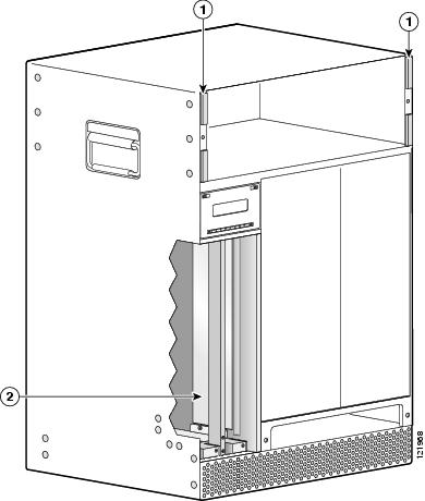
Verify that you need this upgrade. Check the locations in Figure 1 for installed EMI gaskets and RF absorber material. If you already have the EMI gaskets and RF absorber material installed, you do not need to continue with this procedure and you can continue with the installation of the PRE modules.
Document Revision History
Contents
•
Installing the EMI Gasket on the Chassis Sidewall
•
Installing the EMI Gaskets on the Fan Module
•
Installing the RF Absorber Material
•
Obtaining Documentation and Submitting a Service Request
Introduction
Upgrading to a PRE module in the Cisco uBR10012 router might result in unacceptable Cisco manufacturing EMI emission margins. By installing EMI gaskets and RF absorber material in the locations specified, an acceptable margin is met.

Note
This condition is not harmful to the PRE modules or the Cisco uBR10012 router.
Figure 1 Locations of EMI Gaskets and RF Absorber Material
Preparing the Chassis
You need:
•
ESD-preventive wrist strap, antistatic bags, and an antistatic surface
•
EMI gaskets and RF absorber material kit
•
PRE2 modules to replace the PRE1 modules.
•
Lint-free wipes
To prepare the chassis for installation of the EMI gaskets and RF absorber material, do the following:
Step 1
Make sure you are properly grounded.
Step 2
Power down the router.
Step 3
Remove the existing PRE modules from the chassis and place them on an antistatic surface.
Step 4
Loosen the captive screws and pivot the ejector levers away from the modules.
Step 5
Slide the PRE modules out of the chassis and place them in antistatic bags.
Installing the EMI Gasket on the Chassis Sidewall
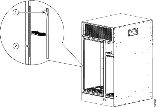
An EMI gasket (51-6555-01) must be installed on the center of the chassis sidewall. (See Figure 2.)
Figure 2 EMI Gasket on the Chassis Sidewall
To attach the EMI gasket to the chassis sidewall, perform the following steps:
Step 1
Peel the adhesive backing off the gasket.
Step 2
Align the sticky side of the gasket to the center of the chassis sidewall and attach it firmly next to the current line card 8/0 EMI gasket. (See Figure 2.)
Installing the EMI Gaskets on the Fan Module
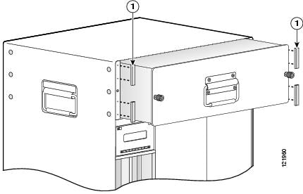
The EMI gaskets are installed on the chassis on either side of the fan module. See Figure 3. This procedure should take 2 to 3 minutes.

Note
EMI gaskets are only required if you are replacing PRE1 modules with PRE2 modules in a Cisco uBR10012 universal broadband router.
Figure 3 Installation Location of the EMI Gaskets
To install the EMI gaskets on the fan module, perform the following steps:
Step 1
Loosen the captive screws on the fan module and pull the fan module out of the chassis far enough so that you can install the EMI gaskets. You do not need to remove the fan module from the chassis.
Step 2
With a clean wipe, wipe off the left and right flanges where the four EMI gaskets will be installed.
Step 3
Peel the backing off the gasket (only prepare one gasket at a time).
Step 4
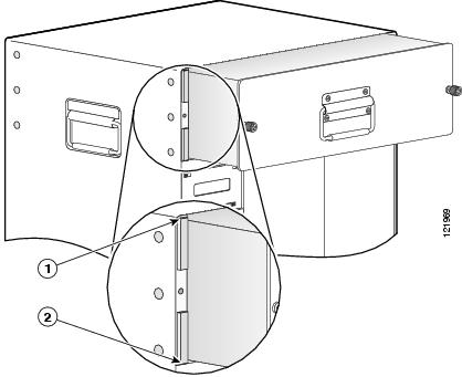
Align the sticky side of the gasket with the flange so that the end of the gasket is level with the top of the flange, see Figure 4.
Figure 4 Aligning the EMI Gasket
Step 5
Carefully place the EMI gasket on the flange and press down to secure the gasket in place.

CautionDo not let the let the gasket slip to either side of the flange. Maintain a distance of at least one-half inch around the captive screw hole in the flange.
Step 6
Peel the backing off the bottom EMI gasket and align the end of the gasket with the bottom of the flange. See Figure 4.
Step 7
Carefully place the gasket on the flange and press down to secure the gasket in place.
Step 8
Repeat Step 3 through Step 7 for the other side of the chassis.
Figure 5 Installed EMI Gaskets
Step 9
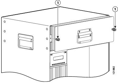
Push the fan module back into the chassis and use the captive screws to secure the fan module in place. Note that the EMI gaskets are compressed when securing the fan to the chassis. See Figure 5.
Installing the RF Absorber Material
RF absorber material is required when you are installing PRE2 modules in your Cisco uBR100012 router. The absorber material is placed on the inside panel of PRE slot B. This procedure should take 4 to 5 minutes.
To install the RF absorber material, do the following:
Step 1
Make sure you are properly grounded.
Step 2
Remove both PRE1 modules from the chassis, if you have not already done so.
Step 3
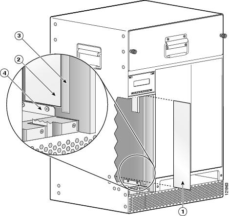
Using a clean lint-free wipe, wipe the inside panel of the PRE module slot B (panel next to the power supplies). Make sure that the edge of the lip and the edge along the raised channel are free of any dust or debris. See Figure 6.

CautionIf the RF absorber material is bubbled or marred by debris left on the surface of the panel or on the lip at the bottom, the PRE2 module may catch on the RF absorber material and not fit properly into the slot.
Figure 6 Aligning the RF Absorber Material with the Raised Channel and Lip
Step 4
Peel the backing from the 2.7 x14.2 inch sheet of RF absorber material. Be very careful not to let any two adhesive covered sections of the material stick together, it is very difficult to unstick.
Step 5
Carefully align the material in the area shown in Figure 6. When you are aligning the material, align it with both the edge of the raised channel and the edge of the lip.

CautionTake special care to properly align this material before securing it in place, the material is difficult to remove once it is securely in place.
Do not allow the RF absorber material to over lap the raised channel or the lip as it can interfere with the PRE2 installation.
Step 6
Lightly press the RF absorber material into place along the raised channel, making sure that there are no bubbles or wrinkles in the material.

Note
You can lift the RF absorber material from the panel to reposition it, but each time you do, the adhesive backing loses some of its integrity.
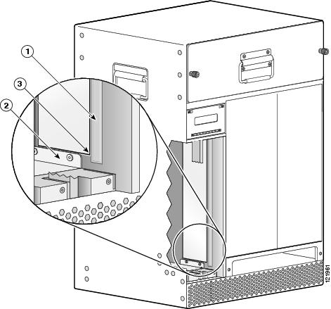
Figure 7 Aligning the RF Absorber Material
Step 7
When the material is properly aligned and laying flat against the surface of the panel, gently press down on the material, starting from the side nearest the raised channel and moving toward the back of the chassis.
Make sure that you don't cause the material to slip out of place and check for any wrinkles or bubbles. Reset the RF absorber material, if necessary.
Part Numbers
Related Documents
Performance Routing Engine Module for the Cisco uBR10012 Universal Broadband Router
Cisco Performance Routing Engine (ESR-PRE2) Upgrade Installation
Cisco Performance Routing Engine 5 Hardware Installation Guide
Cisco uBR10012 Universal Broadband Router Hardware Installation Guide
http://www.cisco.com/en/US/docs/cable/cmts/ubr10012/installation/guide/hig.html
Obtaining Documentation and Submitting a Service Request
For information on obtaining documentation, submitting a service request, and gathering additional information, see the monthly What's New in Cisco Product Documentation, which also lists all new and revised Cisco technical documentation, at:
http://www.cisco.com/en/US/docs/general/whatsnew/whatsnew.html
Subscribe to the What's New in Cisco Product Documentation as an RSS feed and set content to be delivered directly to your desktop using a reader application. The RSS feeds are a free service. Cisco currently supports RSS Version 2.0.
Cisco and the Cisco logo are trademarks or registered trademarks of Cisco and/or its affiliates in the U.S. and other countries. To view a list of Cisco trademarks, go to this URL: www.cisco.com/go/trademarks. Third-party trademarks mentioned are the property of their respective owners. The use of the word partner does not imply a partnership relationship between Cisco and any other company. (1110R)
Copyright © 2004-2011, 2013 Cisco Systems, Inc. All rights reserved.
Contact Cisco
- Open a Support Case

- (Requires a Cisco Service Contract)
 Feedback