Cisco cBR Series Converged Broadband Routers PacketCable and PacketCable Multimedia Configuration Guide for Cisco IOS XE Fuji 16.7.x
Bias-Free Language
The documentation set for this product strives to use bias-free language. For the purposes of this documentation set, bias-free is defined as language that does not imply discrimination based on age, disability, gender, racial identity, ethnic identity, sexual orientation, socioeconomic status, and intersectionality. Exceptions may be present in the documentation due to language that is hardcoded in the user interfaces of the product software, language used based on RFP documentation, or language that is used by a referenced third-party product. Learn more about how Cisco is using Inclusive Language.
- Updated:
- November 24, 2017
Chapter: PacketCable and PacketCable Multimedia
- Finding Feature Information
- Hardware Compatibility Matrix for Cisco cBR Series Routers
- Restrictions for PacketCable Operations
- Information About PacketCable Operations
- How to Configure PacketCable Operations
- Configuration Examples for PacketCable
- Verifying PacketCable Operations
- Information About PacketCable Multimedia Operations
PacketCable and
PacketCable Multimedia
This document describes how to configure the Cisco CMTS for PacketCable and PacketCable Multimedia operations over an existing DOCSIS (1.1and later versions) network.
- Finding Feature Information
- Hardware Compatibility Matrix for Cisco cBR Series Routers
- Restrictions for PacketCable Operations
- Information About PacketCable Operations
- How to Configure PacketCable Operations
- Configuration Examples for PacketCable
- Verifying PacketCable Operations
- Information About PacketCable Multimedia Operations
- How to Configure PCMM Operations
- Configuration Examples for PacketCable Multimedia
- Verifying PCMM Operations
- High Availability Stateful Switchover (SSO) for PacketCable and PacketCable MultiMedia
- Voice MGPI Support
- Additional References
- Feature Information for PacketCable and PacketCable Multimedia
Finding Feature Information
Finding Feature Information
Your software release may not support all the features documented in this module. For the latest feature information and caveats, see the release notes for your platform and software release. To find information about the features documented in this module, and to see a list of the releases in which each feature is supported, see the Feature Information Table at the end of this document.
Use Cisco Feature Navigator to find information about platform support and Cisco software image support. To access Cisco Feature Navigator, go to http://tools.cisco.com/ITDIT/CFN/. An account on http://www.cisco.com/ is not required.
Hardware Compatibility Matrix for Cisco cBR Series Routers
 Note | The hardware components introduced in a given Cisco IOS-XE Release are supported in all subsequent releases unless otherwise specified. |
Restrictions for PacketCable Operations
- To avoid packet drops of voice calls, the Cisco CMTS should be using the default token bucket configuration (cable downstream rate-limit token-bucket shaping). Packet drops are guaranteed to occur when the shaping option is not used (cable downstream rate-limit token-bucket).
- Supports only embedded multimedia terminal adapter (E-MTA) clients. Standalone MTA (S-MTA) clients are not supported.
- PacketCable operations can be configured together with HCCP N+1 redundancy, but the PacketCable states are not synchronized between the Working and Protect interfaces. If a switchover occurs, existing voice calls continue, but when the user hangs up, PacketCable event messages are not generated because the Protect interface is not aware of the previous call states. However, new voice calls can be made and proceed in the normal fashion.
- The 200,000 Hz channel width cannot be used on upstreams that support PacketCable voice calls, or on any upstreams that use Unsolicited Grant Service (UGS) or UGS with Activity Detection (UGS-AD) service flows. Using this small a channel width with voice and other UGS/UGS-AD service flows results in calls being rejected because of “DSA MULTIPLE ERRORS”.
Information About PacketCable Operations
This section provides an overview and other information about PacketCable operations, the components of a PacketCable network, and how they interact with the other components of a DOCSIS cable networks.
- Feature Overview
- Emergency 911 Features
- PacketCable Network Components
- Dynamic Quality of Service
- Dynamic Service Transaction ID Support
- PacketCable Subscriber ID Support
- Benefits
Feature Overview
PacketCable is a program initiative from Cablelabs and its associated vendors to establish a standard way of providing packet-based, real-time video and other multimedia traffic over hybrid fiber-coaxial (HFC) cable networks. The PacketCable specification is built upon the Data-over-Cable System Interface Specifications (DOCSIS) 1.1, but it extends the DOCSIS protocol with several other protocols for use over noncable networks, such as the Internet and the public switched telephone network (PSTN).
This allows PacketCable to be an end-to-end solution for traffic that originates or terminates on a cable network, simplifying the task of providing multimedia services over an infrastructure composed of disparate networks and media types. It also provides an integrated approach to end-to-end call signaling, provisioning, quality of service (QoS), security, billing, and network management.
Emergency 911 Features
PacketCable Emergency 911 Cable Interface Line Card Prioritization
The PacketCable Emergency 911 cable interface line card prioritization feature enables cable interface line cards that are supporting an Emergency 911 call to be given automatic priority over cable interface line cards supporting non-emergency voice calls, even in the case of HCCP switchover events. In such cases, Protect HCCP line card interfaces automatically prioritize service to Emergency 911 voice calls, should Working HCCP cable interface line cards be disrupted. This feature is enabled by default, and may not be disabled with manual configuration.
Note | Emergency 911 cable interface line card prioritization applies only to PacketCable voice calls. |
During HCCP switchover events, cable modems recover in the following sequence:
- Cable modems supporting Emergency 911 voice traffic
- Cable modems supporting non-emergency voice traffic
- Cable modems that are nearing a T4 timeout event, in which service would be disrupted
- Remaining cable modems
To view information about Emergency 911 voice events and cable interface line card prioritization on the Cisco CMTS router, use the show hccp, show cable calls, and show hccp event-history commands in privileged EXEC mode.
PacketCable Emergency 911 Services Listing and History
The enhanced informational support for PacketCable Emergency 911 calls on the Cisco CMTS router provides the following information and related history:
- active Emergency 911 calls
- recent Emergency 911 calls
- regular voice calls
- voice calls made after recent Emergency 911 calls
This feature is enabled and supported with the following configuration and show commands:
To set the call window (in minutes) during which the Cisco CMTS router maintains records of Emergency 911 calls, use the cable high-priority-call-window command in global configuration mode. To remove the call window configuration from the Cisco CMTS router, use the no form of this command:
PacketCable Network Components
A PacketCable network contains a number of components. Some components are the same as those that exist in a DOCSIS 1.1 network, while other components are new entities that create the end-to-end infrastructure that the PacketCable network needs to establish calls. Wherever possible, the PacketCable components and protocols build on existing protocols and infrastructures to simplify implementation and interoperability.
- Cable modem—A customer premises equipment (CPE) device that connects to a DOCSIS 1.0 or DOCSIS 1.1 cable network. All DOCSIS cable modems provide high-speed data connectivity to the Internet, while other cable modems can provide additional features, such as telephone connectivity.
- Cable Modem Termination System (CMTS)—A headend-based router that connects a DOCSIS cable network to the IP backbone network. The CMTS controls the DOCSIS 1.1 MAC layer and enforces the quality of service (QoS) limits that the cable operator guarantees to its subscribers. A typical CMTS services between several hundred and several thousand cable modems.
Note | See the DOCSIS 1.1 specifications for information about cable modem and CMTS operations. |
- Multimedia terminal adapter (MTA)—A CPE device that connects telephones and other end-user devices to the PacketCable network. The PacketCable specification defines two MTA types, an embedded MTA (E-MTA) and a standalone MTA (S-MTA). The E-MTA is an MTA integrated into a DOCSIS 1.1 cable modem, while the S-MTA is a separate MTA that requires a DOCSIS 1.1 cable modem to connect to the cable network.
- Call management server (CMS)—A centrally located server that provides the signaling functions that allow MTAs to establish calls over the network. The CMS uses the Network-based call signaling (NCS) protocol to provide authentication and authorization, call routing, and support for special features such as three-way calling. A PacketCable network could have multiple CMS servers, depending on its size and complexity.
Note | The CMS implements several protocols on top of the Common Open Policy Service (COPS) protocol to communicate with the rest of the PacketCable network. |
- Gate controller (GC)—A server that controls the establishment of gates in the PacketCable network. A gate is a logical entity in the CMTS that ensures that a service flow is authorized for the QoS features it is requesting. A separate gate controls the upstream and downstream directions of a service flow. When a call is established, the GC instructs the CMTS to create each gate and supplies the set of authorized parameters for each gate, which the CMTS uses to authorize the QoS requests that the MTA is making for the call. The GC is also responsible for coordinating the creation of the two sets of gates at each end of the call so that the call can be authorized and established.
Note | A PacketCable network can contain multiple GCs, although only one server at a time is in control of any particular call. Typically, the same workstation provides both the CMS and GC servers. |
- Record keeping server (RKS)—Billing server that collects the information about each call as it is made. The RKS uses the Remote Authentication Dial-In User Service (RADIUS) protocol to collect the billing data from the CMTS and other PacketCable servers. The RKS generates a call data record (CDR) for every call and forwards that information to the appropriate application server at the service provider’s data processing center for further processing.
Dynamic Quality of Service
A key feature of a PacketCable network is a dynamic quality of service (DQoS) capability that is similar to the dynamic services provided by DOCSIS 1.1. However, DOCSIS 1.1 DQoS authorizes and provisions services only in the cable network and does not reserve the resources needed to propagate a call from one endpoint to another across the network.
The PacketCable DQoS extends the DOCSIS 1.1 services across the entire network, so that resources can be dynamically authorized and provisioned from one endpoint to another. This prevents possible theft-of-service attacks and guarantees customers the services they are authorized to use.
Note | PacketCable 1.0 requires that DOCSIS 1.1 be used for resource reservation within the cable network for E-MTA clients. |
Two-Stage Resource Reservation Process
The PacketCable DQoS model uses a two-stage resource reservation process, in which resources are first reserved and then committed. This allows a bidirectional reservation process that ensures that resources are available at both endpoints of the connection before actually placing the call.
When an MTA makes a call request, the local CMTS communicates with the gate controller to authorize the call’s resources. After the resources are authorized, the CMTS reserves the local resources while it negotiates with the remote end for the resources that are required at that end.
Note | The CMTS uses DOCSIS 1.1 Dynamic Service Addition (DSA) messages to reserve the resources, and then uses Dynamic Service Change (DSC) messages to commit the resources. |
When all required resources are available, the local CMTS and remote CMTS both commit the resources, allowing traffic to flow. Usage accounting and billing do not begin until the remote MTA picks up and the call is actually in progress.
The DQoS model ensures that both endpoints of a call, as well as the backbone network, have reserved the same bandwidth, and that the bandwidth is reserved only while the call is in progress. When a call terminates, all portions of the network can release the call’s resources and make them available for other users.
Making a Call Using DQoS
DOCSIS 1.1 networks use service flows to implement different QoS policies, but service flows exist only within the cable network. To control the service flows and to extend them across the entire network, a PacketCable network creates and maintains “gates.”
A gate is a logical entity created on the CMTS at each side of a connection that authorizes and establishes a particular DQoS traffic flow. The CMTS communicates with the gate controller to coordinate the creation of matching gates at each side of the connection.
Gates are unidirectional, so separate gates are required for the downstream and upstream traffic flows. The same gate ID, however, is usually used for the downstream and upstream gates for a call. Each CMTS maintains its own set of gates, so a bidirectional traffic flow requires four gates to be created, two gates on the local CMTS and two gates on the remote CMTS.
For a typical call, gates progress through the following stages to create a DQoS traffic flow:
- The local MTA makes a call request, and the gate controller sends a Gate-Allocation command to the CMTS, which creates a gate in response and puts it into the Allocated state.
- The call management server, which might be the same server as the gate controller, parses the call request to translate the destination phone number into the appropriate destination gateway.
- The gate controller verifies that the MTA making the call request is authorized for the required resources and sends a Gate-Set command to the CMTS, which puts the gate into the Authorized state.
- The CMTS on each side of the connection reserves the local resources needed for the call, putting the gate into the Reserved state.
- As the remote CMTS and local CMTS perform gate coordination, their respective gates get put into the Local_Committed and Remote_Committed states.
- When both sides have reserved all required resources, each CMTS puts its gates into the Committed state, allowing traffic to flow.
DQoSLite Based IPv6 Voice Support
DQoSLite is a modem centric solution without notion of gates, to validate and deliver residential voice services over IPv6 to reclaim IPv4 address space. CMTS does not participate in resource reservation and authorization.
DQoSLite leverages elements from PacketCable 2.0. It is SIP based, it's provision mechanism is similar to PacketCable 2.0 and it can be part of an IP Multimedia Subsystem (IMS) infrastructure for the ISP.
The key factors for deploying IPv6 voice solution on this new DQoSLite infrastructure are as follows:
-
It is SIP or IMS based.
-
Support for a wide range of multimedia services.
-
To reclaim some IPv4 address space.
This feature is enabled and supported with the following configuration and show commands:
Dynamic Service Transaction ID Support
DOCSIS 2.0 mandates unique Transaction IDs (TAIDs) across transactions. The TAIDs must be unique and not incremented. The TAIDs are assigned by the senders and sometimes the TAID timeout is mismatched between senders and receivers. This affects the uniqueness of the TAID.
A TAID can be reused when the sender finishes a transaction. Similarly, DOCSIS allows the receiver to identify a transaction by TAID without the SFID. Problems arise in DSD transaction and DSA/DSC interrupted transactions, when these two requirements are combined.
The uniqueness of TAID must be ensured to resolve the interoperability issue. This is done by making the CMTS wait until T10 to reuse the same TAID. A new TAID allocation algorithm is used to fulfill this requirement.
It creates a TAID pool to replace the existing 16-bit counter. This TAID pool is monitored by timers to track the TAID expiration. A flag is assigned to each TAID in the pool to indicate its availability. When new TAID is requested, the dynamic service process checks the availability of the TAID. If the TAID is available, it is allocated to the new service flow, else the request is rejected.
Once the TAID is allocated, the timer starts with T10 expiration time and the TAID flag is set to FALSE to indicate the unavailability of TAID. The dynamic service process keeps track of the timer. When the time expires, the timer stops and the flag is set to TRUE to indicate the availability of TAID.
The TAID pool is allocated and initialized at the process initialization. All timers associated with the TAIDs are added as leaf timers to the process' parent timer.
PacketCable Subscriber ID Support
The PacketCable Subscriber ID feature adds a subscriber ID to all Gate Control messages and enhances error codes returned from the Cisco CMTS router.
Previously, the Gate ID was unique only to individual CMTS systems, with the CMTS proxying all CMS Gate Control messaging through a central device, which manages the CMTS connections on behalf of the CMS. The CMS had a single Common Open Policy Service (COPS) association to the proxy device. Therefore, the Gate IDs could be duplicated when using multiple CMTS systems.
A subscriber ID is added to each Gate Control message to disambiguate the Gate IDs between the CMS and proxy device. The subscriber ID parameter is added to the following COPS messages:
The subscriber ID is available at the CMS and is used in the Gate-Set messages. Additionally, the error codes returned from CMTS or its proxy are enhanced to include more specific information about gate operation failures.
To enable this feature, use the packetcable gate send-subscriberID command in global configuration mode.
Benefits
The PacketCable feature offers the following benefits to service providers and their customers:
Integrated Services on a Cable Network
PacketCable allows cable operators the ability to offer multimedia, real-time services, in addition to data connectivity, across their entire network. These services could include basic telephony with lifeline support, as well as telephony that offers competitive extended calling services. Operators can deploy new services while heavily leveraging their existing network infrastructures.
The widespread use of IP as the standard transport mechanism for data networks today is enabling many advanced Internet applications such as multimedia e-mail, real-time chat, streaming media (including music and video), and videoconferencing. The PacketCable initiative provides the network architecture for a cable operator to deliver these services quickly and economically.
Standardized Provisioning
PacketCable provides a standardized, efficient method to provision IP services for individual subscribers, because PacketCable specifications define a uniform, open, and interoperable network. Cable operators are assured of standardized provisioning and the associated lower costs of deployment.
Interoperability
Customer premises equipment (CPE) devices account for a major portion of the capital expense in deploying a VoIP solution at a cable plant. The PacketCable specifications ensure that vendors will build MTA clients that support the voice and other services that cable operators plan to deploy. Because these CPE devices are based on existing DOCSIS-compliant cable modems, time and cost of development is minimized.
Interoperability with the other components of the PacketCable network is also guaranteed because of the standards-based approach to the specifications. Any PacketCable-certified component will be able to interoperate within a network that conforms to the PacketCable standards.
Secure Architecture
Because PacketCable is built upon the security features available in DOCSIS 1.1, cable operators will be assured of networks that are secure from end to end, with a high standard of security that prevents the most common theft-of-service attacks. The comprehensive, standards-based PacketCable specifications are designed to create a network that is as secure as the public switched telephone network (PSTN).
CALEA Support
The PacketCable architecture was designed to accommodate the 1994 Communications Assistance for Law Enforcement Act (CALEA), which requires telecommunications carriers to assist law-enforcement agencies in conducting court-ordered electronic surveillance. PacketCable networks will be able to provide the two types of information that a carrier must provide, depending on the type of court order:
- Call-identifying information—The carrier must provide the call-identifying information for calls to or from an intercept target. For telephone calls, this information includes the phone numbers called by the target or calling the target.
- Call content—The carrier must provide the content of calls to or from an intercept target. For telephone calls, this real-time content is the voice conversation.
How to Configure PacketCable Operations
This section contains the following tasks to configure the PacketCable feature. Each task is required unless otherwise identified as optional.
- Enabling PacketCable Operation
- Disabling PacketCable Operation
- Configuring PacketCable Operation
- Enabling Both PacketCable and Non-PacketCable UGS Service Flows
- Enabling PacketCable Subscriber ID Support
- Configuring RADIUS Accounting for RKS Servers
- PacketCable Client Accept Timeout
Enabling PacketCable Operation
To enable PacketCable operation, use the following commands beginning in user EXEC mode. This is a required procedure.
Disabling PacketCable Operation
To disable PacketCable operation, use the following commands beginning in user EXEC mode. This procedure is required only when you no longer want the Cisco CMTS to support PacketCable signaling.
Configuring PacketCable Operation
To configure the different parameters that affect PacketCable operations, use the following commands beginning in user EXEC mode. All of these procedures are optional, because each parameter is set to a default that is appropriate for typical PacketCable operations.
Enabling Both PacketCable and Non-PacketCable UGS Service Flows
By default, when PacketCable operations are enabled using the packetcable command, cable modems must follow the PacketCable protocol when requesting Unsolicited Grant Service (UGS) service flows. This prevents DOCSIS cable modems that do not support PacketCable operations from using DOCSIS-style UGS service flows.
If you have a mixed network that contains both PacketCable and non-PacketCable DOCSIS CMs, you can use the packetcable authorize vanilla-docsis-mta command to enable both types of UGS service flows. This is an optional procedure.
 Tip | Use the show packetcable global command to display whether non-PacketCable UGS service flows have been enabled. |
Enabling PacketCable Subscriber ID Support
To include subscriber identification in GATE-OPEN and GATE-CLOSE Gate Control messages, use the packetcable gate send-subscriberID command in global configuration mode.
Configuring RADIUS Accounting for RKS Servers
To enable the Cisco CMTS router to communicate with the Record Keeping Servers (RKS servers) using the RADIUS protocol, use the following commands. This is a required procedure.
Troubleshooting Tips
If the connection between a PacketCable CMS and the Cisco CMTS router is not completely established, and the PacketCable CMS does not correctly terminate the session by sending a TCP FIN message, the connection shows a COPS server in the output of the show cops server command.
PacketCable Client Accept Timeout
The PacketCable Client Accept Timeout feature supports COPS for PacketCable on the Cisco CMTS router. This feature also allows you to set timeout values for COPS Telnet connections on the Cisco CMTS router, and for clearing COPS Telnet sessions.
Telnet errors on the network or Cisco CMTS router might cause incomplete COPS sessions to be created. In order to address this issue, the timeout timer enables clearing and cleaning of allocated resources for the stale COPS Telnet sessions on the Cisco CMTS router.
The timeout timer applies to each COPS Telnet connection on the Cisco CMTS router. When this timeout setting expires, it terminates the Telnet session and clears supporting resources on the Cisco CMTS router.
| Command or Action | Purpose | |
|---|---|---|
| Step 1 | enable
Example: Router> enable |
Enables privileged EXEC mode. |
| Step 2 | configure
terminal
Example: Router# configure terminal |
Enters global configuration mode. |
| Step 3 | packetcable
timer {T0
timer-value
|
T1
timer-value |
multimedia
T1
timer-value}
Example: Router(config)# packetcable timer T0 300000 Example: Router(config)# packetcable timer T1 400000 Example: Router(config)# packetcable timer multimedia T1 400000 |
Sets the PacketCable timer value. |
| Step 4 | end
Example: Router(config)# end |
Returns to privileged EXEC mode. |
Troubleshooting Tips
If the connection between a PacketCable CMS and the Cisco CMTS router is not completely established, and the PacketCable CMS does not correctly terminate the session by sending a TCP FIN message, the connection shows a COPS server in the output of the show cops server command.
Configuration Examples for PacketCable
This section provides a PacketCable configuration example.
Example: Typical PacketCable Configuration
This section provides a typical configuration for a Cisco CMTS router that has been configured for PacketCable operations, using default parameters. To use this configuration, you must change the IP addresses for the RADIUS and RKS servers to match the addresses for the servers in your network.
!
version 15.5
no parser cache
no service pad
service timestamps debug datetime msec localtime show-timezone
service timestamps log datetime msec localtime show-timezone
no service password-encryption
service internal
service udp-small-servers max-servers no-limit
service tcp-small-servers max-servers no-limit
!
hostname Router
!
no logging rate-limit
aaa new-model
!
!
aaa group server radius a
 server 10.9.62.12 auth-port 1813 acct-port 1812
 server 10.9.62.13 auth-port 1813 acct-port 1812
!
aaa accounting network default start-stop group radius group a
aaa session-id common
enable password <delete>
!
cable modulation-profile 2 request 0 16 0 8 qpsk scrambler 152 no-diff 64 fixed uw16
cable modulation-profile 2 initial 5 34 0 48 qpsk scrambler 152 no-diff 128 fixed uw16
cable modulation-profile 2 station 5 34 0 48 qpsk scrambler 152 no-diff 128 fixed uw16
cable modulation-profile 2 short 6 75 6 8 16qam scrambler 152 no-diff 144 shortened uw8
cable modulation-profile 2 long 8 220 0 8 16qam scrambler 152 no-diff 160 shortened uw8
cable modulation-profile 5 request 0 16 2 8 qpsk scrambler 152 no-diff 64 fixed uw16
cable modulation-profile 5 initial 5 34 0 48 qpsk scrambler 152 no-diff 128 fixed uw16
cable modulation-profile 5 station 5 34 0 48 qpsk scrambler 152 no-diff 128 fixed uw16
cable modulation-profile 5 short 6 78 7 8 16qam scrambler 152 no-diff 144 shortened uw16
cable modulation-profile 5 long 8 220 0 8 16qam scrambler 152 no-diff 160 shortened uw16
cable qos profile 5 max-burst 1200
cable qos profile 5 max-downstream 2000
cable qos profile 5 max-upstream 128
cable qos profile 5 priority 5
cable qos profile 5 privacy
cable qos profile 7 guaranteed-upstream 87
cable qos profile 7 max-upstream 87
cable qos profile 7 privacy
no cable qos permission create
no cable qos permission update
cable qos permission modems
cable qos permission enforce 5
cable time-server
no cable privacy accept-self-signed-certificate
ip subnet-zero
!
!
no ip domain-lookup
ip domain-name cisco.com
ip host tftp 10.8.8.8
ip host cnr 10.9.62.17
!
packetcable
packetcable element-id 12456
!
!
!
interface Tunnel0
 ip address 10.55.66.3 255.255.255.0
 load-interval 30
 tunnel source TenGigabitEthernet 4/1/0
 tunnel destination 172.27.184.69
!
interface Tunnel10
 ip address 10.0.1.1 255.255.0.0
!
interface TenGigabitEthernet 4/1/0
 ip address 10.9.60.10 255.255.0.0
 no ip redirects
 no ip mroute-cache
 full-duplex
!
interface TenGigabitEthernet 4/1/0
 ip address 172.22.79.44 255.255.254.0
 no ip redirects
 no ip mroute-cache
 full-duplex
!
interface Cable3/0
 ip address 10.3.1.33 255.255.255.0 secondary
 ip address 10.4.1.1 255.255.255.0 secondary
 ip address 10.4.1.33 255.255.255.0 secondary
 ip address 10.3.1.1 255.255.255.0
 ip helper-address 10.9.62.17
 load-interval 30
 no keepalive
 cable downstream annex B
 cable downstream modulation 64qam
 cable downstream interleave-depth 32
 cable downstream frequency 55500000
 cable upstream 0 modulation-profile 2
 no cable upstream 0 shutdown
 cable upstream 1 frequency 12000000
 cable upstream 1 power-level 0
 cable upstream 1 channel-width 3200000
 cable upstream 1 data-backoff automatic
 cable upstream 1 modulation-profile 2
 cable upstream 1 shutdown
 cable upstream 2 frequency 16000000
 cable upstream 2 power-level 0
 cable upstream 2 channel-width 3200000
 cable upstream 2 data-backoff automatic
 cable upstream 2 modulation-profile 2
 no cable upstream 2 shutdown
 cable upstream 3 frequency 20000000
 cable upstream 3 power-level 0
 cable upstream 3 channel-width 3200000
 cable upstream 3 data-backoff automatic
 cable upstream 3 modulation-profile 2
 no cable upstream 3 shutdown
 cable upstream 4 frequency 24000000
 cable upstream 4 power-level 0
 cable upstream 4 channel-width 3200000
 cable upstream 4 data-backoff automatic
 no cable upstream 4 shutdown
 cable upstream 5 frequency 28000000
 cable upstream 5 power-level 0
 cable upstream 5 channel-width 3200000
 cable upstream 5 data-backoff automatic
 cable upstream 5 modulation-profile 2
 no cable upstream 5 shutdown
 cable dhcp-giaddr policy
!
router eigrp 48849
 network 1.0.0.0
 network 10.0.0.0
 auto-summary
 no eigrp log-neighbor-changes
!
ip default-gateway 10.9.0.1
ip classless
ip route 0.0.0.0 0.0.0.0 172.22.78.1
ip route 10.8.0.0 255.255.0.0 10.9.0.1
ip route 192.168.80.0 255.255.255.0 Tunnel0
ip route 192.168.80.0 255.255.255.0 172.27.184.69
ip route 10.255.254.254 255.255.255.255 10.9.0.1
no ip http server
ip pim bidir-enable
!
!
cdp run
!
!
radius-server host 10.9.62.12 auth-port 1813 acct-port 1812 key 0000000000000000
radius-server retransmit 3
radius-server vsa send accounting
!
line con 0
 exec-timeout 0 0
 privilege level 15
line aux 0
line vty 0 4
 session-timeout 33
 exec-timeout 0 0
 password <deleted>
!
ntp clock-period 17179976
ntp server 1.9.35.8
end
Verifying PacketCable Operations
To verify and maintain information about PacketCable operations, use one or more of the following commands:
- show packetcable global
- show packetcable gate
- show packetcable gate ipv6
- show packetcable gate dqos
- show packetcable gate counter commit
To verify the PacketCable configuration, values for the Element ID, maximum number of gates, and the different CMTS-based DQoS timers, use the show packetcable global command in privileged EXEC mode.
Router# show packetcable global
Packet Cable Global configuration:
Enabled   : Yes
Element-ID: 12456
Max Gates : 1048576
Allow non-PacketCable UGS
Default Timer value -
  T0      : 30000 msec
  T1      : 300000 msec
To verify information about one or more gates in the gate database, use the show packetcable gate command as shown in the following example:
Router# show packetcable gate summary
GateID     i/f          SubscriberID   GC-Addr        State     Type  SFID(us) SFID(ds)
13582      Ca8/1/0      3.18.1.4       20.5.0.254     RECOVERY  Dqos  74
29962      Ca8/1/0      3.18.1.5       20.5.0.254     RECOVERY  Dqos  73
46354      Ca8/1/0      ------         20.5.0.254     RECOVERY  Dqos  72
62738      Ca8/1/0      ------         20.5.0.254     RECOVERY  Dqos           69
Total number of  gates = 4
Total Gates committed(since bootup or clear counter) = 8
To verify information about one or more PacketCable gates associated with IPv6 subscriber IDs in the gate database, use the show packetcable gate ipv6 command as shown in the following example:
Router# show packetcable gate ipv6 summary
GateID     i/f                     SubscriberID                State   SFID(us) SFID(ds)
13582      Ca8/1/0      2001:40:1:42:C0B4:84E5:5081:9B5C       COMMIT    74
29962      Ca8/1/0      2001:40:1:42:C0B4:84E5:5081:9B5C       COMMIT    73
46354      Ca8/1/0      2001:40:1:42:C0B4:84E5:5081:9B5C       COMMIT    72
62738      Ca8/1/0      2001:40:1:42:C0B4:84E5:5081:9B5C       COMMIT             69
Total number of  gates = 4
Total Gates committed(since bootup or clear counter) = 8
To verify information about one or more PacketCable gates associated with IPv4 subscriber IDs in the gate database, use the show packetcable gate dqos command as shown in the following example:
Router# show packetcable gate dqos summary
GateID     i/f          SubscriberID   GC-Addr        State     Type  SFID(us) SFID(ds)
13576      Ca8/1/0      40.1.43.60     10.74.58.5     COMMIT    DQoS  527      528
29956      Ca8/1/0      40.1.43.56     10.74.58.5     COMMIT    DQoS  525      526
Total number of DQOS gates = 2
Total Gates committed(since bootup or clear counter) = 346
To verify the total number of gates that the Cisco CMTS router has moved to the Committed state since the router was last reset, or since the counter was last cleared, use the show packetcable gate counter commit command as shown in the following example:
Router# show packetcable gate counter commit
Total Gates committed (since bootup or clear counter) = 132
Verifying Emergency 911 Calls
This section provides a few examples to illustrate how you can use the show cable calls and show cable modem calls commands to verify different scenarios associated with Emergency 911 calls.
The following example displays Emergency 911 calls made on the Cable8/1/1 interface on the Cisco CMTS router during the window set for high priority calls:
Router# show cable calls
Interface   ActiveHiPriCalls  ActiveAllCalls  PostHiPriCallCMs  RecentHiPriCMs
C5/0/0  				0                 0               0                 0
C5/0/1  				0                 0               0                 0
C5/1/0  				0                 0               0                 0
C5/1/1  				0                 0               0                 0
C5/1/2  				0                 0               0                 0
C5/1/3  				0                 0               0                 0
C5/1/4  				0                 0               0                 0
C6/0/0  				0                 0               0                 0
C6/0/1  				0                 0               0                 0
C7/0/0  				0                 0               0                 0
C7/0/1  				0                 0               0                 0
C8/1/0  				0                 0               0                 0
C8/1/1  				1                 1               0                 0
C8/1/2  				0                 0               0                 0
C8/1/3  				0                 0               0                 0
C8/1/4  				0                 0               0                 0
Total       1                 1               0                 0
The following example displays the change on the Cisco CMTS router when this Emergency 911 calls ends:
Router# show cable calls
Interface   ActiveHiPriCalls  ActiveAllCalls  PostHiPriCallCMs  RecentHiPriCMs
C5/0/0  				0                 0               0                 0
C5/0/1  				0                 0               0                 0
C5/1/0  				0                 0               0                 0
C5/1/1  				0                 0               0                 0
C5/1/2  				0                 0               0                 0
C5/1/3  				0                 0               0                 0
C5/1/4  				0                 0               0                 0
C6/0/0  				0                 0               0                 0
C6/0/1  				0                 0               0                 0
C7/0/0  				0                 0               0                 0
C7/0/1  				0                 0               0                 0
C8/1/0  				0                 0               0                 0
C8/1/1 				 0                 0               0                 1
C8/1/2  				0                 0               0                 0
C8/1/3  				0                 0               0                 0
C8/1/4  				0                 0               0                 0
Total       0                 0               0                 1
The following example displays information that is available when making a voice call from the same MTA to another MTA on the same interface:
Router# show cable calls
Interface   ActiveHiPriCalls  ActiveAllCalls  PostHiPriCallCMs  RecentHiPriCMs
C5/0/0  				0                 0               0                 0
C5/0/1  				0                 0               0                 0
C5/1/0  				0                 0               0                 0
C5/1/1  				0                 0               0                 0
C5/1/2  				0                 0               0                 0
C5/1/3  				0                 0               0                 0
C5/1/4  				0                 0               0                 0
C6/0/0  				0                 0               0                 0
C6/0/1  				0                 0               0                 0
C7/0/0  				0                 0               0                 0
C7/0/1  				0                 0               0                 0
C8/1/0  				0                 0               0                 0
C8/1/1  				0                 2               1                 1
C8/1/2  				0                 0               0                 0
C8/1/3  				0                 0               0                 0
C8/1/4  				0                 0               0                 0
Total       0                 2               1                 1
The following example displays information that is available when a voice call from the same MTA to another MTA on the same interface ends:
Router# show cable calls
Interface   ActiveHiPriCalls  ActiveAllCalls  PostHiPriCallCMs  RecentHiPriCMs
C5/0/0  				0                 0               0                 0
C5/0/1  				0                 0               0                 0
C5/1/0  				0                 0               0                 0
C5/1/1  				0                 0               0                 0
C5/1/2  				0                 0               0                 0
C5/1/3  				0                 0               0                 0
C5/1/4  				0                 0               0                 0
C6/0/0  				0                 0               0                 0
C6/0/1  				0                 0               0                 0
C7/0/0  				0                 0               0                 0
C7/0/1  				0                 0               0                 0
C8/1/0  				0                 0               0                 0
C8/1/1  				0                 0               0                 1
C8/1/2  				0                 0               0                 0
C8/1/3 				 0                 0               0                 0
C8/1/4  				0                 0               0                 0
Total       0                 0               0                 1
The following examples display the show cable modem calls command output on the Cisco CMTS router over a period of time, with changing call status information. The call information disappears when a call ends.
Router# show cable modem calls
Cable Modem Call Status Flags:
H: Active high priority calls
R: Recent high priority calls
V: Active voice calls (including high priority)
MAC Address    IP Address      I/F       Prim  CMCallStatus  LatestHiPriCall
                                         Sid                    (min:sec)
0000.cab7.7b04 10.10.155.38    C8/1/1/U0 18    R                   0:39
Router# show cable modem calls
Cable Modem Call Status Flags:
H: Active high priority calls
R: Recent high priority calls
V: Active voice calls (including high priority)
MAC Address    IP Address      I/F       Prim  CMCallStatus  LatestHiPriCall
                                         Sid                    (min:sec)
The following example displays a new Emergency 911 call on the Cisco CMTS router:
Router# show cable modem calls
Cable Modem Call Status Flags:
H: Active high priority calls
R: Recent high priority calls
V: Active voice calls (including high priority)
MAC Address    IP Address      I/F       Prim  CMCallStatus  LatestHiPriCall
                                         Sid                    (min:sec)
0000.cab7.7b04 10.10.155.38    C8/1/1/U0 18    HV                  1:30
The following example displays the end of the Emergency 911 call on the Cisco CMTS router:
Router# show cable modem calls
Cable Modem Call Status Flags:
H: Active high priority calls
R: Recent high priority calls
V: Active voice calls (including high priority)
MAC Address    IP Address      I/F       Prim  CMCallStatus  LatestHiPriCall
                                         Sid                    (min:sec)
0000.cab7.7b04 10.10.155.38    C8/1/1/U0 18    R                   0:3
The following example displays a non-emergency voice call on the Cisco CMTS router from the same MTA:
Router# show cable modem calls
Cable Modem Call Status Flags:
H: Active high priority calls
R: Recent high priority calls
V: Active voice calls (including high priority)
MAC Address    IP Address      I/F       Prim  CMCallStatus  LatestHiPriCall
                                         Sid                    (min:sec)
0000.ca36.f97d 10.10.155.25    C8/1/1/U0 5     V                    -
0000.cab7.7b04 10.10.155.38    C8/1/1/U0 18    RV                  0:30
The following example displays the end of the non-emergency voice call on the Cisco CMTS router:
Router# show cable modem calls
Cable Modem Call Status Flags:
H: Active high priority calls
R: Recent high priority calls
V: Active voice calls (including high priority)
MAC Address    IP Address      I/F       Prim  CMCallStatus  LatestHiPriCall
                                         Sid                    (min:sec)
0000.cab7.7b04 10.10.155.38    C8/1/1/U0 18    R                   0:36
Information About PacketCable Multimedia Operations
The PacketCable Multimedia (PCMM) feature is a powerful implementation of the CableLabs® standards for PacketCable Multimedia. PCMM provides enhanced QoS for multimedia applications, voice, and bandwidth-intensive services over a DOCSIS (DOCSIS 1.1 and later versions) network.
The Cisco CMTS router supports DOCSIS QoS for SIP-based telephones and SIP video phones, Bandwidth-on-Demand applications, and network-based gaming applications, all of which place extensive bandwidth demands on the network.
This section provides information about the following aspects of PacketCable Multimedia for the Cisco CMTS router, emphasizing PCMM components that are configured with the Cisco IOS command-line interface later in this document:
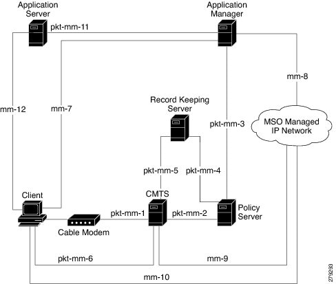
PCMM Overview
The following network components are required to support the PCMM feature:
- Application Server—Responsible for relaying client requests to the Application Manager.
- Application Manager—Responsible for application or session-level state and for applying session control domain (SCD) policy.
- Policy Server—Responsible for applying the RCD policy and for managing relationships between the Application Manager and a Cisco CMTS router.
- Cisco CMTS router—Responsible for performing admission control and managing network resources through DOCSIS service flows.
Figure below provides an architectural overview of the PCMM functionality:
PCMM Enhancements over PacketCable 1.x
PacketCable Multimedia is a service delivery framework that leverages and uses as much of existing PacketCable 1.x deployments and functionality as possible. Furthermore, PCMM offers powerful enhancements to the VoIP service delivery framework with straightforward CLI implementation. The key enhancements that the PCMM provides are:
- Time and volume based network resource authorizations are based on DOCSIS 1.1 Quality of Service (QoS) mechanisms.
- Event-based network resource auditing and management functions.
- Secure infrastructure that protects all interfaces at appropriate levels.
- Preauthorized model from PacketCable 1.x, where the PCMM gate installation and management is supplemented with service flow creation, modification and deletion functions. Together, these provide a secure, network-based QoS.
PCMM and High Availability Features on the Cisco CMTS Router
High Availability on the Cisco CMTS router accommodates synchronization of service flows created for the PCMM applications and the PCCM gate.
PCMM Gates
PCMM Gate Overview and PCMM Dynamic Quality of Service
A PacketCable 1.x gate defines QoS parameters and policy-based authorization for subscribers, and a specific envelope of network resources. A PacketCable 1.x gate also maintains classifiers for originating and terminating IP addresses and ports.
The subscriber ID can identify both IPv4 and IPv6 addresses of either the cable modem or the client CPE.
PacketCable 1.x defines a preauthorization model. The PacketCable gates are created and installed at the Cisco CMTS router prior to network resource reservation or activation requests. This process, termed gate control, is managed through a COPS-based policy interface on the Cisco CMTS router.
In PCMM, this COPS-based interface is enhanced for QoS life-cycle management. PCMM gates maintain service flow creation, modification and deletion functions to provide for network-based QoS. Multiple PCMM gates and service flow policies can be maintained on the Cisco CMTS router at a given time, and these PCMM gates are fully interoperable with PacketCable 1.x gates.
When a cable modem subscriber requests bandwidth for a network-intensive application, the network Policy Server sends a Gate-Set message to the Cisco CMTS router. This message contains QoS, service flow, and billing information for this subscriber. This gate profile information is maintained on the Cisco CMTS router, to include PCMM gate states and PCMM state transitions.
The Cisco CMTS router initiates service flows with cable modems, and optimizes DOCSIS resource availability on the Cisco CMTS router for bandwidth-intensive service flows characteristic to PCMM.
Restrictions
On some upstream paths, best effort service flows are configured on some modems with Committed Information Rate (CIR). When a number of bandwidth requests are queued in the modems, only a few requests are sent to the CMTS. This occurs due to congestion of sending requests caused by higher number of service flows, greater traffic and small size of packets. Therefore, only a few best effort service flow requests are satisfied by the CMTS.
PCMM Persistent Gate
Persistent Gate is a feature by which PCMM gate information is maintained for cable modems that go offline. This gate information is quickly enabled after a cable modem returns online. When a cable modem returns online, the Cisco CMTS router scans PCMM gates previously stored, and initiates service to the cable modem according to the respective PCMM gate. This re-enabled service maintains traffic support profiles for that gate, and allocates DOCSIS resources based on the new online subscriber.
PCMM Interfaces
PCMM optimizes the IPC handshake between the cable interface line card and the Route Processor (RP) for the Cisco CMTS router. Additional PCMM interface changes from PacketCable 1.x include the handling for COPS interface and distributed cable interface line cards.
PCMM to COPS Interface
PCMM differs from PacketCable 1.x in handling COPS sessions. The COPS sessions on PCMM use TCP port number 3918 by default. Whereas, PacketCable uses the DQoS specification for TCP port requirements and COPS sessions.
When the PCMM module initializes for the first time, a PCMM registry is added to the cable interface line card and the route processor. The PCMM module also registers the PCMM COPS client with the COPS layer on the Cisco CMTS router.
PCMM and Distributed Cable Interface Line Cards
As with PacketCable 1.x, PCMM uses IPC messages for voice support. When PCMM gates are created on the Network Processing Engine (NPE) or route processor (RP), the PCMM gate parameters are sent to cable interface line cards. IPC maintains all communication between the NPE or RP, and the cable interface line cards.
Event messaging is used with PCMM to support billing information based on Gate-Set messages. Event messaging for distributed cable interface line cards originates from the line cards, based on the success of DSX operation.
The PCMM module also registers the PCMM COPS client with the COPS layer.
PCMM Unicast and Multicast
In unicast transmission, content is sent to a unique user. In multicast transmission, content is sent to multiple users simultaneously.
PCMM Multicast Session Range
You can configure a PCMM multicast session range by specifying IPv4 IP addresses and a mask for a PCMM multicast group. The PCMM multicast session range enables the Cisco CMTS router to accept Gate-Set messages from the PCMM Policy Server. If a PCMM multicast session range is configured, the Cisco CMTS router does not allow you to create multicast sessions using other sources such as Internet Group Management Protocol (IGMP) and DOCSIS Set-Top Gateway (DSG).
How to Configure PCMM Operations
The following tasks describe how to enable PCMM operations and configure its related features on the Cisco CMTS router:
Enabling PCMM Operations on the Cisco CMTS Router
To enable PCMM operations on the Cisco CMTS router:
| Command or Action | Purpose | |
|---|---|---|
| Step 1 | enable
Example: Router> enable |
Enables privileged EXEC mode. |
| Step 2 | configure
terminal
Example: Router# configure terminal |
Enters global configuration mode. |
| Step 3 | packetcable
multimedia
Example: Router(config)# packetcable multimedia |
Enables and displays PCMM processing on the Cisco CMTS router. This command enables the Cisco CMTS router to start or stop responding to PCMM COPS messages received from the PCMM Policy Server. |
| Step 4 | packetcable
authorize
vanilla-docsis-mta
Example: Router(config)# packetcable authorize vanilla-docsis-mta |
Allows non-DQoS MTAs to send DOCSIS DSX messages. |
| Step 5 | packetcable
gate
maxcount
n
Example: Router(config)# packetcable gate maxcount 890 |
Sets the maximum number of PCMM gates in the gate database. |
| Step 6 | packetcable
timer
multimedia
T1
timer-value
Example: Router(config)# packetcable timer multimedia T1 300000 |
Sets the timeout value for T1 timer used in PCMM gate processing. |
| Step 7 | clear
packetcable
gate
counter
commit
[dqos
|
multimedia]
Example: Router(config)# clear packetcable gate counter commit multimedia |
(Optional) Clears the specified PCMM gate counter. |
| Step 8 | end
Example: Router(config)# end |
Returns to privileged EXEC mode. |
Configuring a PCMM Multicast Session Range
A PCMM multicast session range enables the Cisco CMTS router to use a range of IP addresses for a PCMM multicast group.
Ensure that PCMM is configured using the packetcable multimedia command.
Note |
|
| Command or Action | Purpose | |
|---|---|---|
| Step 1 | enable
Example: Router> enable |
Enables privileged EXEC mode. |
| Step 2 | configure
terminal
Example: Router# configure terminal |
Enters global configuration mode. |
| Step 3 | cable
multicast
source
pcmm
Example: Router(config)# cable multicast source pcmm |
Enables PCMM-based multicast service on the Cisco CMTS router and enters multicast session range configuration mode. |
| Step 4 | session-range
ip-addressip-mask
Example: Router(config)# session-range 229.0.0.0 255.0.0.0 |
Configures a session range for the PCMM multicast group. |
| Step 5 | end
Example:
Router(config)# end
|
Returns to privileged EXEC mode. |
Configuration Examples for PacketCable Multimedia
The following sections provide configuration examples for PCMM operations on the Cisco CMTS router:
- Example: Enabling PCMM Operations on the Cisco CMTS Router
- Example: Enabling a Multicast Session Range on the Cisco CMTS Router
Example: Enabling PCMM Operations on the Cisco CMTS Router
Router# configure terminal
Router(config)# packetcable multimedia
Router(config)# packetcable authorize vanilla-docsis-mta
Router(config)# packetcable gate maxcount 890
Router(config)# packetcable timer multimedia 30000
Example: Enabling a Multicast Session Range on the Cisco CMTS Router
Router# configure terminal
Router(config)# cable multicast source pcmm
Router(config)# session-range 229.0.0.0 255.0.0.0
Verifying PCMM Operations
Use the following show commands to verify PCMM operations:
- show packetcable gate multimedia
- show cable multicast db
- show interface wideband-cable
- show cable multicast qos
To verify the PCMM multicast gates, use the show packetcable gate multimedia command as shown in the following example:
Router# show packetcable gate multimedia multicast summary
GateID     i/f          SubscriberID   GC-Addr        State     Type  SFID(us) SFID(ds)
134        Ca5/0/0      60.1.1.202     2.39.26.19     COMMIT    MM             4
Total number of Multimedia-MCAST gates = 1
Total Gates committed(since bootup or clear counter) = 1
To verify the PCMM IPv6 gates, use the show packetcable gate multimedia ipv6command as shown in the following example:
Router# show packetcable gate multimedia ipv6 summary
Load for five secs: 10%/1%; one minute: 9%; five minutes: 9%
Time source is NTP, 03:29:42.153 EST Mon Nov 9 2015

GateID     i/f                     SubscriberID                State   SFID(us) SFID(ds)
409        Ca5/0/2      2001:420:2C7F:FC38:58AF:E36A:80:213A   COMMIT             1326
16789      Ca5/0/2      2001:420:2C7F:FC38:AC40:A49A:F80A:8D0B COMMIT    1321
33177      Ca5/0/2      2001:420:2C7F:FC38:DD49:72A3:2ECC:8770 COMMIT             1322
49577      Ca5/0/2      2001:420:2C7F:FC38:485:31DF:C88B:E315  COMMIT    1308
65953      Ca5/0/2      2001:420:2C7F:FC38:5AB:AA0B:34AD:ACCF  COMMIT    1336
82337      Ca5/0/2      2001:420:2C7F:FC38:5AB:AA0B:34AD:ACCF  COMMIT             1337
98721      Ca5/0/2      2001:420:2C7F:FC38:5570:EF2E:7565:D36A COMMIT             1316
115097     Ca5/0/2      2001:420:2C7F:FC38:6009:EF26:F573:7356 COMMIT             1318
131489     Ca5/0/2      2001:420:2C7F:FC38:7D4A:BC50:3FD:CA7   COMMIT    1312
147873     Ca5/0/2      2001:420:2C7F:FC38:E83E:8259:AEF6:5624 COMMIT    1332


Total number of Multimedia gates = 10
Total Gates committed(since bootup or clear counter) = 1024
To verify all the PCMM client entries available with the multicast database, use the show cable multicast db command as shown in the following example:
Router# show cable multicast db client pcmm
Interface : Bundle1
Session (S,G) : (*,229.2.2.12)
Fwd Intf     Bundle Intf  Host Intf    CM MAC         CPE IP           Gate-ID SFID
Wi1/1/0:0    Bundle1      Ca5/0/0      0018.6852.8056 60.1.1.202       134	4
To verify multicast sessions on a specific wideband cable interface, use the show interface wideband-cable command as shown in the following example:
Router# show interface wideband-cable 1/1/0:0 multicast-sessions
Default Multicast Service Flow 3 on Wideband-Cable1/1/0:0
Multicast Group    : 229.2.2.12
         Source    : N/A
         Act GCRs  : 1
         Interface : Bu1                   State: A      GI: Bu1         RC: 0
		GCR       : GC   SAID    SFID    Key   GQC    GEn
                     512  8196    4       0     512    0
To verify the attribute-based assignment of service flows on a specific wideband cable interface, use the show interface wideband-cable command as shown in the following example:
Router# show interface wideband-cable 1/1/0:0
service-flow 4 verbose
Sfid                                    : 4
Mac Address                             : ffff.ffff.ffff
Type                                    : Secondary(Static)
Direction                               : Downstream
Current State                           : Active
Current QoS Indexes [Prov, Adm, Act]    : [4, 4, 4]
Active Time                             : 05:26
Required Attributes                     : 0x00000000
Forbidden Attributes                    : 0x00000000
Aggregate Attributes                    : 0x00000000
Multicast Sid                           : 8196
Traffic Priority                        : 0
Maximum Sustained rate                  : 0 bits/sec
Maximum Burst                           : 3044 bytes
Minimum Reserved Rate                   : 250000 bits/sec
Minimum Packet Size                     : 0 bytes
Maximum Latency                         : 0 usecs
Peak Rate                               : 0 bits/sec
Admitted QoS Timeout                    : 200 seconds
Active QoS Timeout                      : 0 seconds
Packets                                 : 0
Bytes                                   : 0
Rate Limit Delayed Packets              : 0
Rate Limit Dropped Packets              : 0
Current Throughput                      : 0 bits/sec, 0 packets/sec
Application Priority                    : 0
Low Latency App                         : No
Blaze/JIB3 DS Statistic Index           : 0
Forwarding Interface                    : Wi1/1/0:0
Classifiers: NONE
To verify that the PCMM-based MQoS gate controllers are created using the correct session ranges, use the show cable multicast qoscommand as shown in the following example:
Router# show cable multicast qos group-qos
Group QOS Index    Service Class    Control    Igmp Limit    Override  App
 DEFAULT           mcast_default     Aggregate  NO-LIMIT
 1                 SDV_SD            Single      ---          No        CLI
 512               SDV_HD            Single      ---          No        PCMM
High Availability Stateful Switchover (SSO) for PacketCable and PacketCable MultiMedia
Enhanced high availability support enables the synchronization of PacketCable and PacketCable MultiMedia (PCMM) gates during switchover events on the Cisco CMTS router. This enhancement is enabled by default.
This functionality uses the existing per-interface HCCP commands that are used to associate the working and protect interfaces in the case of N+1 redundancy.
PacketCable and PCMM with Admission Control
A PacketCable or PacketCable Multimedia network contains a number of components that benefit from Admission Control QoS. Admission Control manages and optimizes QoS for PacketCable and PCMM in these ways:
- QoS (based on DOCSIS 1.1 or later versions) for voice and data
- Cable modem registration
- CMS
- Gateway controllers (GC)
- Record keeping servers (RKS)
- Video telephony
When configuring Admission Control with either PacketCable or PCMM, PacketCable or PCMM must be fully operational on the Cisco CMTS headend prior to gaining the benefits from Admission Control.
Voice MGPI Support
The multiple grants per interval (MGPI) feature enables the Cisco CMTS router to map multiple PacketCable Multimedia gates (application flows) to a single DOCSIS service flow using UGS traffic profiles of the same cable modem. In other words, the Cisco CMTS router increases the number of grants per interval for each application flow based on a single service flow, resulting in multiple grants per interval.
The MGPI feature supports the flow-aggregated voice MGPI functionality based on CableLabs PacketCable Specification (PKT-SP-MM-I05-091029). The flow-aggregated MGPI functionality allows the application manager to use the UGS traffic profile to explicitly set the number of grants per interval and place several application flows on a single gate. This results in an aggregated view for event messages, volume, and time usage limits.
- Voice Support Over DOCSIS 3.0 E-MTAs
- PacketCable and PCMM Call Trace
- Verifying PacketCable and PCMM Statistics
Voice Support Over DOCSIS 3.0 E-MTAs
PacketCable and PCMM services are supported on embedded multimedia terminal adapters (E-MTAs). An E-MTA is a network element that contains the interface to a physical voice device, a network interface, and all signaling and encapsulation functions required for the VoIP transport, class features signaling, and QoS signaling.
PacketCable and PCMM Call Trace
To effectively capture signaling information, this functionality buffers signaling for a configured number of PacketCable or PCMM gates. By default, only ten user-configured gate traces are saved in a buffer. After the specified number is reached, any subsequent gate signaling information does not get buffered. When one of the gates being traced is deleted, gate signaling of a new gate is buffered.
Use the cable dynamic-qos trace command in global configuration mode to enable the call trace functionality for PacketCable and PacketCable Multimedia gates on the Cisco CMTS router. You will have to specify the number of subscribers for whom call trace needs to be enabled.
Verifying PacketCable and PCMM Statistics
Use the following commands to verify PacketCable and PCMM statistics on the Cisco CMTS router:
- show interface cable dynamic-service statistics
- show interface cable packetcable statistics
- show packetcable cms
To verify dynamic service statistics based on the cable interface, use the show interface cable dynamic-service statistics command as shown in the following example:
Router# show interface cable 7/1/0 dynamic-service statistics
		Upstream        Downstream
DSA REQ      0               5
DSA RSP      5               0
DSA ACK      0               5
DSC REQ      0               5
DSC RSP      5               0
DSC ACK      0               5
DSD REQ      0               0
DSD RSP      0               0
Retransmission counts
             Upstream        Downstream
DSA REQ      0               0
DSA RSP      0               0
DSA ACK      0               0
DSC REQ      0               5
DSC RSP      5               0
DSC ACK      0               0
DSD REQ      0               0
DSD RSP      0               0
To verify PacketCable IPC statistics based on the cable interface, use the show interface cable packetcable statistics command as shown in the following example:
Router# show interface cable 7/1/0 packetcable statistics
Packetcable IPC Statistics on RP
Msg   create     gate       gate       gate set   dsd
      gie        set        del        notify     notify
Sent  0          10         0          0          0
Rcvd  0          0          0          10         0
Packetcable IPC Statistics on LC
Msg   create     gate       gate       gate set   dsd
      gie        set        del        notify     notify
Sent  0          0          0          10         0
Rcvd  0          10         0          0          0
To verify all gate controllers that are currently connected to the PacketCable client, use the show packetcable cms command as shown in the following example:
Router# show packetcable cms
GC-Addr        GC-Port  Client-Addr    COPS-handle  Version PSID Key PDD-Cfg
1.100.30.2     47236    2.39.34.1      0x2FF9E268/1    4.0   0    0   0
2.39.26.19     55390    2.39.34.1      0x2FF9D890/1    1.0   0    0   2
To verify all gate controllers including the COPS servers for which the PacketCable connection is gone down, use the show packetcable cms command with the all keyword as shown in the following example:
Router# show packetcable cms all
GC-Addr        GC-Port  Client-Addr    COPS-handle  Version PSID Key PDD-Cfg
1.100.30.2     47236    2.39.34.1      0x2FF9E268/1    4.0   0    0   0
2.39.26.19     55390    2.39.34.1      0x2FF9D890/1    1.0   0    0   2
1.10.30.22     42307    2.39.34.1      0x0       /0    4.0   0    0   0
To verify gate controller statistics, use the show packetcable cms command with the keyword, verbose, as shown in the following example:
Router# show packetcable cms verbose
Gate Controller
     Addr         :     1.100.30.2
     Port         :     47236
     Client Addr  :     2.39.34.1
     COPS Handle  :     0x2FF9E268
     Version      :     4.0
     Statistics   :
        gate del =  0  gate del ack =  0   gate del err = 0
        gate info = 0  gate info ack = 0  gate info err = 0
        gate open =  0  gate report state = 0
        gate set =  0  gate set ack =  0   gate set err = 0
        gate alloc = 0 gate alloc ack = 0  gate alloc err = 0
        gate close =  0
Gate Controller
     Addr         :     2.39.26.19
     Port         :     55390
     Client Addr  :     2.39.34.1
     COPS Handle  :     0x2FF9D890
     Version      :     1.0
     Statistics   :
        gate del =  0  gate del ack =  0   gate del err = 0
        gate info = 0  gate info ack = 0  gate info err = 0
        gate open =  0  gate report state = 0
        gate set =  2  gate set ack =  2   gate set err = 0
        PCMM Timers Expired
        Timer T1 =  0  Timer T2 =  0 Timer T3 = 0 Timer T4 = 0
GC-Addr        GC-Port  Client-Addr    COPS-handle  Version PSID Key PDD-Cfg
1.100.30.2     47236    2.39.34.1      0x2FF9E268/1    4.0   0    0   0
2.39.26.19     55390    2.39.34.1      0x2FF9D890/1    1.0   0    0   2
Additional References
Related Documents
|
Related Topic |
Document Title |
|---|---|
|
Cisco IOS commands |
|
|
CMTS commands |
Cisco CMTS Cable Command Reference http://www.cisco.com/en/US/docs/ios/cable/command/reference/cbl_book.html |
|
N+1 redundancy |
N+1 Redundancy for the Cisco CMTS Routers |
|
NTP or SNTP Configuration |
To configure the Cisco CMTS router to use Network Time Protocol (NTP) or Simple Network Time Protocol (SNTP) to set its system clock, see the “Performing Basic System Management” chapter in the “System Management” section of the Cisco IOS Configuration Fundamentals Configuration Guide. |
Standards
|
Standards1 |
Title |
|---|---|
|
PKT-SP-MM-I06-110629 |
PacketCable™ Specification Multimedia Specification |
|
ITU X.509 V3 |
International Telecommunications Union (ITU) X.509 Version 3.0 standard |
|
PKT-EM-I03-011221 |
PacketCable™ Event Message Specification |
|
PKT-SP-DQOS-I04-021018 |
PacketCable™ Dynamic Quality-of-Service Specification |
|
PKT-SP-EC-MGCP-I04-011221 |
PacketCable™ Network-Based Call Signaling Protocol Specification |
|
PKT-SP-ESP-I01-991229 |
PacketCable™ Electronic Surveillance Specification |
|
PKT-SP-ISTP-I02-011221 |
PacketCable™ Internet Signaling Transport Protocol (ISTP) Specification |
|
PKT-SP-PROV-I03-011221 |
PacketCable™ MTA Device Provisioning Specification |
MIBs
|
MIBs |
MIBs Link |
|---|---|
|
No new or changed MIBs are supported by this feature. |
To locate and download MIBs for selected platforms, Cisco software releases, and feature sets, use Cisco MIB Locator found at the following URL: |
RFCs
|
RFCs |
Title |
|---|---|
|
RFC 1321 |
The MD5 Message-Digest Algorithm |
|
RFC 1510 |
The Kerberos Network Authentication Service (V5) |
|
RFC 2138 |
Remote Authentication Dial In User Service (RADIUS) |
|
RFC 2205 |
Resource ReSerVation Protocol (RSVP) |
|
RFC 2327 |
SDP: Session Description Protocol |
|
RFC 2748 |
The COPS (Common Open Policy Service) Protocol |
Technical Assistance
|
Description |
Link |
|---|---|
|
The Cisco Support and Documentation website provides online resources to download documentation, software, and tools. Use these resources to install and configure the software and to troubleshoot and resolve technical issues with Cisco products and technologies. Access to most tools on the Cisco Support and Documentation website requires a Cisco.com user ID and password. |
Feature Information for PacketCable and PacketCable Multimedia
Use Cisco Feature Navigator to find information about platform support and software image support. Cisco Feature Navigator enables you to determine which software images support a specific software release, feature set, or platform. To access Cisco Feature Navigator, go to http://www.cisco.com/go/cfn. An account on Cisco.com is not required.
Note | The table below lists only the software release that introduced support for a given feature in a given software release train. Unless noted otherwise, subsequent releases of that software release train also support that feature. |
|
Feature Name |
Releases |
Feature Information |
|---|---|---|
|
PacketCable and PacketCable Multimedia Unicast |
Cisco IOS XE Everest 16.6.1 |
This feature was integrated into Cisco IOS XE Everest 16.6.1 on the Cisco cBR Series Converged Broadband Routers. |
|
PacketCable and PacketCable Multimedia Multicast |
Cisco IOS XE Everest 16.6.1 |
This feature was integrated into Cisco IOS XE Everest 16.6.1 on the Cisco cBR Series Converged Broadband Routers. |
|
DQoSLite Based IPv6 Voice Support |
Cisco IOS XE Everest 16.6.1 |
This feature was integrated into Cisco IOS XE Everest 16.6.1 on the Cisco cBR Series Converged Broadband Routers. |
 Feedback