Introduction
This document describes the basic configuration and troubleshooting on Cisco IOS® XE devices.
Prerequisites
Requirements
Cisco recommends that you have knowledge of these topics:
- Basic understanding of DCI overlays and multicast
Components Used
The information in this document is based on these software and hardware versions:
- ASR1004 running software 03.16.00.S
- CSR100v(VXE) running software 3.16.03.S
The information in this document was created from the devices in a specific lab environment. All of the devices used in this document started with a cleared (default) configuration. If your network is live, ensure that you understand the potential impact of any command.
Background Information
Virtual Extensible LAN (VXLAN) is becoming more popular as a Data Center Interconnect (DCI) solution. The VXLAN feature is used to provide Layer-2 extension over the Layer-3/Public Routing domain. This document discusses basic configuration and troubleshooting on Cisco IOS XE devices.
The Configure and Verify sections of this document cover two scenarios:
- Scenario A describes a VXLAN configuration between three Data Centers in multicast mode.
- Scenario B describes a VXLAN configuration between two Data Centers in unicast mode.
Configure
Scenario A: Configure VXLAN Between Three Data Centers in Multicast Mode
Base Configuration
Multicast mode requires both unicast and multicast connectivity between sites. This configuration guide uses Open Shortest Path First (OSPF) to provide unicast connectivity, and bidirectional Protocol Independent Multicast (PIM) to provide multicast connectivity.
Here is the base configuration on all three Data Centers for multicast mode of operation:
!
DC1#show run | sec ospf
router ospf 1
network 10.1.1.1 0.0.0.0 area 0
network 10.10.10.4 0.0.0.3 area 0
!
PIM bidirectional configuration:
!
DC1#show run | sec pim
ip pim bidir-enable
ip pim send-rp-discovery scope 10
ip pim bsr-candidate Loopback1 0
ip pim rp-candidate Loopback1 group-list 10 bidir
!
access-list 10 permit 239.0.0.0 0.0.0.255
!
DC1#
!
In addition, PIM sparse mode is enabled under all L3 interfaces, including the loopback:
!
DC1#show run interface lo1
Building configuration...
Current configuration : 83 bytes
!
interface Loopback1
ip address 10.1.1.1 255.255.255.255
ip pim sparse-mode
end
Also ensure that multicast routing is enabled on your device and that you see the multicast mroute table being populated.
Network Diagram
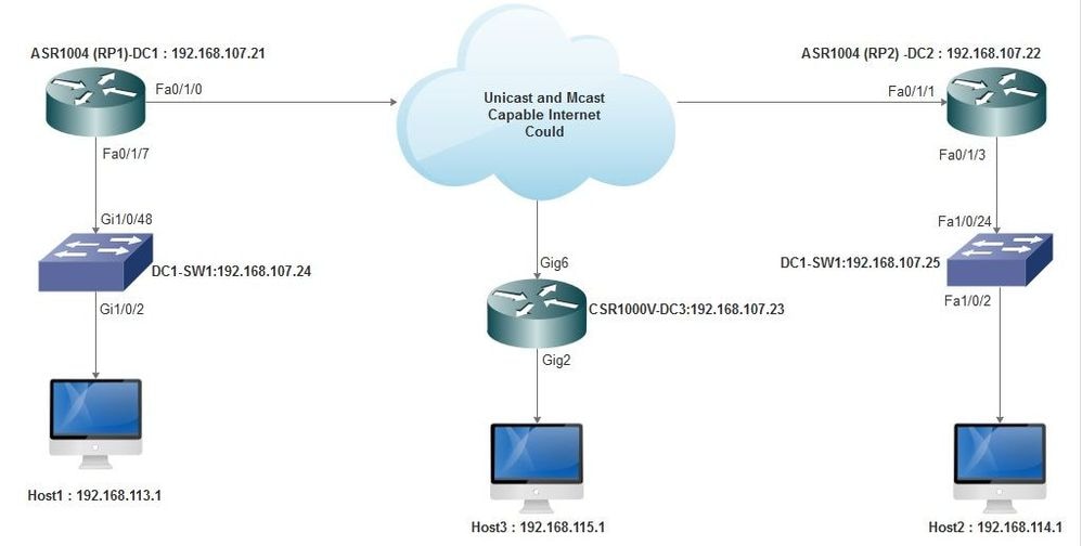 Unicast and Multicast Capable Internet
DC1(VTEP1) Configuration
!
!
Vxlan udp port 1024
!
Interface Loopback1
ip address 10.1.1.1 255.255.255.255
ip pim sparse-mode
!
Define the VNI members and the member interface under bridge-domain configuration:
!
bridge-domain 1
member vni 6001
member FastEthernet0/1/7 service-instance 1
!
Create the network virtual interface (NVE) and define the VNI members that need to be extended over the WAN to other Data Centers:
!
interface nve1
no ip address
shut
member vni 6001 mcast-group 10.0.0.10
!
source-interface Loopback1
!
Create service instances over the LAN interface (that is, the interface that connects the LAN network) to overlay the particular VLAN (802.1q tagged traffic) - in this case, VLAN 1:
!
interface FastEthernet0/1/7
no ip address
negotiation auto
cdp enable
no shut
!
Remove the VLAN tag before sending the traffic across the overlay, and push it after the return traffic is being sent into the VLAN:
!
service instance 1 ethernet
encapsulation unagged
!
DC2(VTEP2) Configuration
!
!
Vxlan udp port 1024
!
interface Loopback1
ip address 10.2.2.2 255.255.255.255
ip pim sparse-mode
!
!
bridge-domain 1
member vni 6001
member FastEthernet0/1/3 service-instance 1
!
!
interface nve1
no ip address
member vni 6001 mcast-group 10.0.0.10
!
source-interface Loopback1
shut
!
!
interface FastEthernet0/1/3
no ip address
negotiation auto
cdp enable
no shut
!
service instance 1 ethernet
encapsulation untagged
!
DC3(VTEP3) Configuration
!
!
Vxlan udp port 1024
!
interface Loopback1
ip address 10.3.3.3 255.255.255.255
ip pim sparse-mode
!
!
bridge-domain 1
member vni 6001
member GigabitEthernet2 service-instance 1
!
interface nve1
no ip address
shut
member vni 6001 mcast-group 10.0.0.10
!
source-interface Loopback1
!
interface gig2
no ip address
negotiation auto
cdp enable
no shut
!
service instance 1 ethernet
encapsulation untagged
!
Scenario B: Configure VXLAN Between Two Data Centers in Unicast Mode
Network Diagram
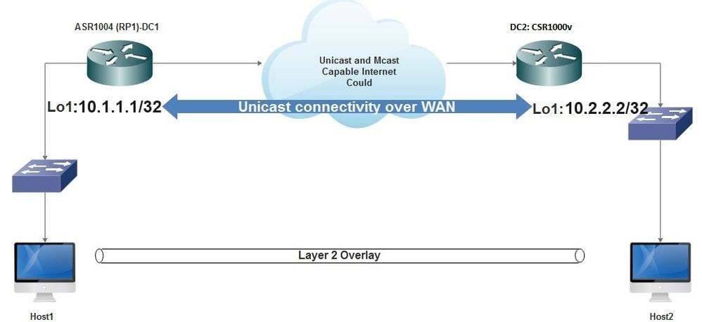 Unicast Connectivity Over WAN
DC1 Configuration
!
interface nve1
no ip address
member vni 6001
! ingress replication shold be configured as peer data centers loopback IP address.
!
ingress-replication 10.2.2.2
!
source-interface Loopback1
!
!
interface gig0/2/1
no ip address
negotiation auto
cdp enable
!
service instance 1 ethernet
encapsulation untagged

!
!
!
bridge-domain 1
member vni 6001
member gig0/2/1 service-instance 1
DC2 Configuration
!
interface nve1
no ip address
member vni 6001
ingress-replication 10.1.1.1
!
source-interface Loopback1
!

!
interface gig5
no ip address
negotiation auto
cdp enable
!
service instance 1 ethernet
encapsulation untagged

!
!
bridge-domain 1
member vni 6001
member gig5 service-instance 1
Verify
Scenario A: Configure VXLAN Between Three Data Centers in Multicast Mode
After you have completed the configuration for Scenario A, the connected hosts in each Data Center must be able to reach each other within the same broadcast domain.
Use these commands to verify the configurations. Some examples are provided under Scenario B.
Router#show nve vni
Router#show nve vni interface nve1
Router#show nve interface nve1
Router#show nve interface nve1 detail
Router#show nve peers
Scenario B: Configure VXLAN Between Two Data Centers in Unicast Mode
On DC1:
DC1#show nve vni
Interface    VNI     Multicast-group    VNI state
nve1        6001           N/A               Up

DC1#show nve interface nve1 detail
Interface: nve1, State: Admin Up, Oper Up Encapsulation: Vxlan
source-interface: Loopback1    (primary:10.1.1.1 vrf:0)
Pkts In     Bytes In      Pkts Out     Bytes Out
60129       6593586        55067        5303698

DC1#show nve peers
Interface     Peer-IP      VNI        Peer state
nve1          10.2.2.2       6000          -
On DC2:
DC2#show nve vni

Interface    VNI        Multicast-group    VNI state

nve1         6000             N/A               Up


DC2#show nve interface nve1 detail

Interface: nve1, State: Admin Up, Oper Up Encapsulation: Vxlan

source-interface: Loopback1 (primary:10.2.2.2 vrf:0)

Pkts In     Bytes In      Pkts Out       Bytes Out

70408       7921636        44840         3950835


DC2#show nve peers

Interface      Peer-IP       VNI       Peer state

  nve           10.1.1.1      6000         Up


DC2#show bridge-domain 1

Bridge-domain 1 (3 ports in all)

State: UP Mac learning: Enabled

Aging-Timer: 300 second(s)

BDI1 (up)

GigabitEthernet0/2/1 service instance 1

vni 6001

AED  MAC address     Policy   Tag      Age  Pseudoport

0    7CAD.74FF.2F66  forward  dynamic  281  nve1.VNI6001, VxLAN src: 10.1.1.1 dst: 10.2.2.2

0    B838.6130.DA80  forward  dynamic  288  nve1.VNI6001, VxLAN src: 10.1.1.1 dst: 10.2.2.2

0    0050.56AD.1AD8  forward  dynamic  157  nve1.VNI6001, VxLAN src: 10.1.1.1 dst: 10.2.2.2
Troubleshoot
The commands described in the Verify section provide basic troubleshooting steps. These additional diagnostics can be helpful when the system is not working.

Note: Some of these diagnostics can cause increased memory and CPU utilization.
Debug Diagnostics
#debug nve error

*Jan 4 20:00:54.993: NVE-MGR-PEER ERROR: Intf state force down successful for mcast nodes cast nodes

*Jan 4 20:00:54.993: NVE-MGR-PEER ERROR: Intf state force down successful for mcast nodes cast nodes

*Jan 4 20:00:54.995: NVE-MGR-PEER ERROR: Intf state force down successful for peer nodes eer nodes

*Jan 4 20:00:54.995: NVE-MGR-PEER ERROR: Intf state force down successful for peer nodes
#show nve log error

[01/01/70 00:04:34.130 UTC 1 3] NVE-MGR-STATE ERROR: vni 6001: error in create notification to Tunnel

[01/01/70 00:04:34.314 UTC 2 3] NVE-MGR-PEER ERROR: Intf state force up successful for mcast nodes

[01/01/70 00:04:34.326 UTC 3 3] NVE-MGR-PEER ERROR: Intf state force up successful for peer nodes

[01/01/70 01:50:59.650 UTC 4 3] NVE-MGR-PEER ERROR: Intf state force down successful for mcast nodes

[01/01/70 01:50:59.654 UTC 5 3] NVE-MGR-PEER ERROR: Intf state force down successful for peer nodes

[01/01/70 01:50:59.701 UTC 6 3] NVE-MGR-PEER ERROR: Intf state force up successful for mcast nodes

[01/01/70 01:50:59.705 UTC 7 3] NVE-MGR-PEER ERROR: Intf state force up successful for peer nodes

[01/01/70 01:54:55.166 UTC 8 61] NVE-MGR-PEER ERROR: Intf state force down successful for mcast nodes

[01/01/70 01:54:55.168 UTC 9 61] NVE-MGR-PEER ERROR: Intf state force down successful for peer nodes

[01/01/70 01:55:04.432 UTC A 3] NVE-MGR-PEER ERROR: Intf state force up successful for mcast nodes

[01/01/70 01:55:04.434 UTC B 3] NVE-MGR-PEER ERROR: Intf state force up successful for peer nodes

[01/01/70 01:55:37.670 UTC C 61] NVE-MGR-PEER ERROR: Intf state force down successful for mcast nodes
#show nve log event

[01/04/70 19:48:51.883 UTC 1DD16 68] NVE-MGR-DB: Return vni 6001 for pi_hdl[0x437C9B68]

[01/04/70 19:48:51.884 UTC 1DD17 68] NVE-MGR-DB: Return pd_hdl[0x1020010] for pi_hdl[0x437C9B68]

[01/04/70 19:48:51.884 UTC 1DD18 68] NVE-MGR-DB: Return vni 6001 for pi_hdl[0x437C9B68]

[01/04/70 19:49:01.884 UTC 1DD19 68] NVE-MGR-DB: Return pd_hdl[0x1020010] for pi_hdl[0x437C9B68]

[01/04/70 19:49:01.884 UTC 1DD1A 68] NVE-MGR-DB: Return vni 6001 for pi_hdl[0x437C9B68]

[01/04/70 19:49:01.885 UTC 1DD1B 68] NVE-MGR-DB: Return pd_hdl[0x1020010] for pi_hdl[0x437C9B68]

[01/04/70 19:49:01.885 UTC 1DD1C 68] NVE-MGR-DB: Return vni 6001 for pi_hdl[0x437C9B68]

[01/04/70 19:49:11.886 UTC 1DD1D 68] NVE-MGR-DB: Return pd_hdl[0x1020010] for pi_hdl[0x437C9B68]

[01/04/70 19:49:11.886 UTC 1DD1E 68] NVE-MGR-DB: Return vni 6001 for pi_hdl[0x437C9B68]

[01/04/70 19:49:11.887 UTC 1DD1F 68] NVE-MGR-DB: Return pd_hdl[0x1020010] for pi_hdl[0x437C9B68]

[01/04/70 19:49:11.887 UTC 1DD20 68] NVE-MGR-DB: Return vni 6001 for pi_hdl[0x437C9B68]

[01/04/70 19:49:21.884 UTC 1DD21 68] NVE-MGR-DB: Return pd_hdl[0x1020010] for pi_hdl[0x437C9B68]
Embedded Packet Capture
The Embedded Packet Capture (EPC) feature that is available in Cisco IOS XE software can provide additional information for troubleshooting.
For example, this capture explains the packet being encapsulated by VXLAN:
EPC configuration (TEST_ACL is the access-list used to filter the capture data):
#monitor capture TEST access-list TEST_ACL interface gigabitEthernet0/2/0 both

#monitor capture TEST buffer size 10

#monitor capture TEST start
Here is the packet dump that results:
# show monitor capture TEST buffer dump

# monitor capture TEST export bootflash:TEST.pcap       // with this command
you can export the capture in pcap format to the bootflash,
which can be downloaded and opened in wireshark.
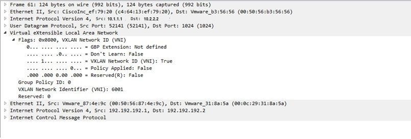
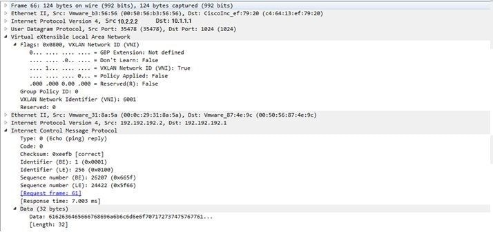
Here is an example that explains how simple Internet Control Message Protocol (ICMP) works over VXLAN.
Address Resolution Protocol (ARP) sent over VXLAN overlay:
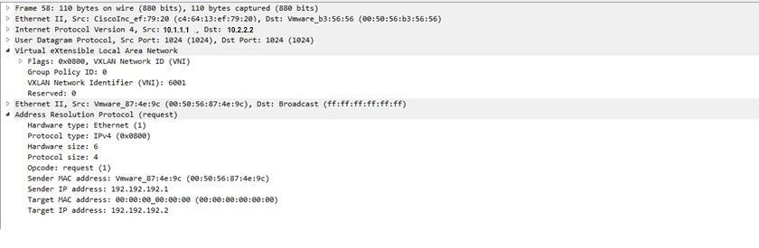
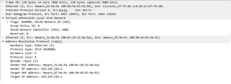
ARP response:
ICMP request:
ICMP response:
Additional Debug and Troubleshooting Commands
This section describes a few more debug and troubleshooting commands.
In this example, the highlighted parts of the debug show that the NVE interface could not join the multicast group. Therefore, the VXLAN encapsulation was not enabled for VNI 6002. These debug results point to multicast issues on the network.
#debug nve all

*Jan 5 06:13:55.844: NVE-MGR-DB: creating mcast node for 10.0.0.10

*Jan 5 06:13:55.846: NVE-MGR-MCAST: IGMP add for (0.0.0.0,10.0.0.10) was failure

*Jan 5 06:13:55.846: NVE-MGR-DB ERROR: Unable to join mcast core tree

*Jan 5 06:13:55.846: NVE-MGR-DB ERROR: Unable to join mcast core tree

*Jan 5 06:13:55.846: NVE-MGR-STATE ERROR: vni 6002: error in create notification to mcast

*Jan 5 06:13:55.846: NVE-MGR-STATE ERROR: vni 6002: error in create notification to mcast

*Jan 5 06:13:55.849: NVE-MGR-TUNNEL: Tunnel Endpoint 10.0.0.10 added

*Jan 5 06:13:55.849: NVE-MGR-TUNNEL: Endpoint  10.0.0.10 added

*Jan 5 06:13:55.851: NVE-MGR-EI: Notifying BD engine of VNI 6002 create

*Jan 5 06:13:55.857: NVE-MGR-DB: Return vni 6002 for pi_hdl[0x437C9B28]

*Jan 5 06:13:55.857: NVE-MGR-EI: VNI 6002: BD state changed to up, vni state to Down
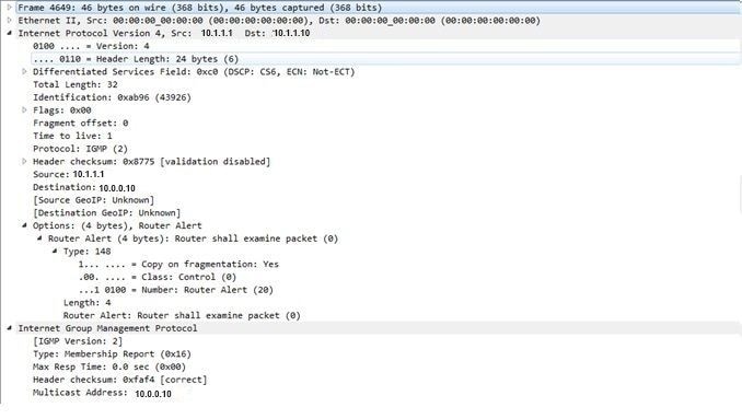
Here is the Internet Group Management Protocol (IGMP) membership report which can be sent once the VNI joins the mcast group:
This example shows the expected debug result after you configure a VNI under NVE for Multicast mode, if Multicast is working as expected:
*Jan 5 06:19:20.335: NVE-MGR-DB: [IF 0x14]VNI node creation

*Jan 5 06:19:20.335: NVE-MGR-DB: VNI Node created [437C9B28]

*Jan 5 06:19:20.336: NVE-MGR-PD: VNI 6002 create notification to PD

*Jan 5 06:19:20.336: NVE-MGR-PD: VNI 6002 Create notif successful, map [pd 0x1020017] to [pi 0x437C9B28]

*Jan 5 06:19:20.336: NVE-MGR-DB: creating mcast node for  10.0.0.10

*Jan 5 06:19:20.342: NVE-MGR-MCAST: IGMP add for (0.0.0.0,10.0.0.10) was successful

*Jan 5 06:19:20.345: NVE-MGR-TUNNEL: Tunnel Endpoint 10.0.0.10 added

*Jan 5 06:19:20.345: NVE-MGR-TUNNEL: Endpoint 10.0.0.10  added

*Jan 5 06:19:20.347: NVE-MGR-EI: Notifying BD engine of VNI 6002 create

*Jan 5 06:19:20.347: NVE-MGR-DB: Return pd_hdl[0x1020017] for pi_hdl[0x437C9B28]

*Jan 5 06:19:20.347: NVE-MGR-DB: Return vni 6002 for pi_hdl[0x437C9B28]

*Jan 5 06:19:20.349: NVE-MGR-DB: Return vni state Create for pi_hdl[0x437C9B28]

*Jan 5 06:19:20.349: NVE-MGR-DB: Return vni state Create for pi_hdl[0x437C9B28]

*Jan 5 06:19:20.349: NVE-MGR-DB: Return vni 6002 for pi_hdl[0x437C9B28]

*Jan 5 06:19:20.351: NVE-MGR-EI: L2FIB query for info 0x437C9B28

*Jan 5 06:19:20.351: NVE-MGR-EI: PP up notification for bd_id 3

*Jan 5 06:19:20.351: NVE-MGR-DB: Return vni 6002 for pi_hdl[0x437C9B28]

*Jan 5 06:19:20.352: NVE-MGR-STATE: vni 6002: Notify clients of state change Create to Up

*Jan 5 06:19:20.352: NVE-MGR-DB: Return vni 6002 for pi_hdl[0x437C9B28]

*Jan 5 06:19:20.353: NVE-MGR-PD: VNI 6002 Create to Up State update to PD successful

*Jan 5 06:19:20.353: NVE-MGR-EI: VNI 6002: BD state changed to up, vni state to Up

*Jan 5 06:19:20.353: NVE-MGR-STATE: vni 6002: No state change Up

*Jan 5 06:19:20.353: NVE-MGR-STATE: vni 6002: New State as a result of create Up
Related Information
 Feedback