Introduction
This document describes how to bridge a Layer 2 (L2) network across a Layer 3 (L3) network.
Prerequisites
Requirements
Cisco recommends that you have knowledge of these topics:
- Layer 2 Tunneling Protocol Version 3 (L2TPv3)
- Generic Routing Encapsulation (GRE)
Components Used
This document is not restricted to specific software and hardware versions.
The information in this document was created from the devices in a specific lab environment. All of the devices used in this document started with a cleared (default) configuration. If your network is live, ensure that you understand the potential impact of any command.
Background Information
In many situations, you require a solution in order to aggregate WiFi traffic from hotspots to a central location. In such cases, the solution needs to allow you premise equipment (CPE) devices to bridge the Ethernet traffic from the end host, and encapsulate the packages through the Ethernet traffic to an endpoint.
If you use Aggregation Services Routers (ASRs), the easy way to do this is to use Ethernet over soft GRE. However, for Integrated Service Routers (ISRs) and all other CPE devices, this is not an option. In older Cisco IOS® versions, it was possible to tunnel L2 over GRE by bridging the physical interface with a GRE tunnel interface. Although regular bridging strips the VLAN header from incoming packets, the use of Integrated Routing and Bridging (IRB) on the router can route and bridge the same network layer protocol on the same interface and still allow the router to maintain the VLAN header from one interface to another.
Note: When you configure the bridge-group on the Tunnel interface on older Cisco IOS versions, the Cisco IOS reports that the command is unreleased and unsupported, but it still accepts the command. In more recent versions, this command is completely obsolete, and the error message displays.
The previous solution is not supported by Cisco. The supported solution for bridging an L2 network is to use L2TPv3 as described in this document. L2TPv3 provides support for the transport of various L2 protocols like Ethernet, 802.1q (VLAN), Frame Relay, High-Level Data Link Control (HDLC), and Point-to-Point Protocol (PPP). The focus of this document is Ethernet extension.
Configure
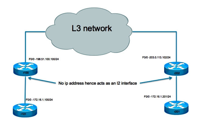
This setup is very basic. Routers r101 and r201 serve as hosts on the same network, while r100 and r202 have one L3 interface and one L2 interface. The objective is to set up the L2TPv3 connection such that r101 and r201 are able to ping each other without the requirement of any routes.
Network Diagram
Tunnel Configuration
The L2TP tunnel configuration involves three steps:
-
Configure an L2TP-class (optional)
This class is used in order to define some authentication and control parameters for the L2TP tunnel. If it is used, the two ends must mirror each other.
l2tp-class test
 hostname stanford
 password 7 082E5C4B071F091805
-
Configure the Pseudowire-class
As the name suggests, this section is used in order to configure the actual tunnel or "pseudowire" between the two endpoints. Define a template that contains pseudowire encapsulation, an endpoint, and control channel protocol.
pseudowire-class test
 encapsulation l2tpv3
 ip local interface Loopback0
 ip pmtu
-
Use Xconnect In Order to Provide the Tunnel Destination
Bind the L2TP pseudowire to the attachment circuit (interface towards local L2 side) and define its destination.
Points to note:
- The attachment circuit itself has no IP address configured.
- The tunnel source configured with the IP local interface is in the pseudowire-class section.
- The tunnel destination is defined with the
xconnect command.
Considerations
- As with the GRE tunneling solution, the use of a router on which to terminate the L2 tunnel still does not allow L2 Protocol Data Unit (PDU) messages to be forwarded across the tunnel. Without the proper L2 protocol tunneling, which is not supported on this device, these messages are consumed by the L2 interface.
- Support for L2 protocol tunneling (Cisco Discovery Protocol, Spanning Tree Protocol, VLAN Trunking Protocol, and Link Layer Discovery Protocol) requires that the device is a switch. This switch needs to be L3 aware in order to be able to tunnel traffic and limit the possible choices.
- The L3 tunneling encapsulation depends on the device that does the tunneling:
- Cisco 7301 supports L2TPv3 encapsulation.
- Cisco 65xx does not support L2 extension with the L2TPv3 tunnel. However, the L2 can be extended across an MLPS core with the Any Transport over MPLS (AToM) option.
- The L2TP tunnel is not supported on the Cisco 4500 switches.
- Only a single xconnect tunnel interface can be configured on a physical interface or sub-interface. A separate interface is needed for each pseudowire endpoint. You cannot configure multiple interfaces with xconnect with the same pw-class and the same L2TP IDs.
- The maximum payload Maximum Transmission Unit size for a L2TP tunnel is generally 1460 bytes for traffic that travels over the standard Ethernet. In the case of L2TP over User Datagram Protocol (UDP), the overhead is the result of the IP header (20 bytes), the UDP header (8 bytes), and the L2TP header (12 bytes).
Sample Configuration
Router r101 Configuration
interface Ethernet0/0
 ip address 172.16.1.100 255.255.255.0
Router r100 Configuration
pseudowire-class test
 encapsulation l2tpv3
 protocol none
 ip local interface fast 0/0
!
interface FastEthernet0/0
 description WAN
 ip address 198.51.100.100 255.255.255.0
!
interface FastEthernet0/1
 description LAN
 no ip address
 speed 100
 full-duplex
 xconnect 203.0.113.102 1 encapsulation l2tpv3 manual pw-class test
 l2tp id 1 2
!
ip route 0.0.0.0 0.0.0.0 198.51.100.1
Router r202 Configuration
pseudowire-class test
 encapsulation l2tpv3
 protocol none
 ip local interface fast 0/0
!
interface FastEthernet0/0
 description WAN
 ip address 203.0.113.102 255.255.255.255

interface FastEthernet0/1
 no ip address
 duplex auto
 speed auto
 xconnect 198.51.100.100 1 encapsulation l2tpv3 manual pw-class test
 l2tp id 2 1
Router r201 Configuration
interface Ethernet0/0
 ip address 172.16.1.201 255.255.255.0
Verify
In order to display detailed information about the L2TP control channels that are set up to other L2TP-enabled devices for all L2TP sessions on the router, use the show l2tun tunnel all command.
In order to verify that the L2TPv3 encapsulation works properly, ping a host at the remote site that is supposed to be on the same VLAN. If the ping is succesful, you can use this command in order to confirm that your configuration works properly.
The show arp command displays the Address Resolution Protocol (ARP) cache.
Troubleshoot
There is currently no specific troubleshooting information available for this configuration.
Related Information
 Feedback