Troubleshoot IP Multicast Guide
Available Languages
Download Options
Bias-Free Language
The documentation set for this product strives to use bias-free language. For the purposes of this documentation set, bias-free is defined as language that does not imply discrimination based on age, disability, gender, racial identity, ethnic identity, sexual orientation, socioeconomic status, and intersectionality. Exceptions may be present in the documentation due to language that is hardcoded in the user interfaces of the product software, language used based on RFP documentation, or language that is used by a referenced third-party product. Learn more about how Cisco is using Inclusive Language.
Contents
Introduction
This document describes common problems and solutions for IP multicast.
Prerequisites
Requirements
There are no specific requirements for this document.
Components Used
This document is not restricted to specific software and hardware versions.
The information in this document was created from the devices in a specific lab environment. All of the devices used in this document started with a cleared (default) configuration. If your network is live, ensure that you understand the potential impact of any command.
Background Information
When you troubleshoot multicast routing, the primary concern is the source address. Multicast has a concept of Reverse Path Forwarding (RPF) check. When a multicast packet arrives on an interface, the RPF process checks to ensure that this incoming interface is the outgoing interface used by unicast routing in order to reach the source of the multicast packet. This RPF check process prevents loops. Multicast routing does not forward a packet unless the source of the packet passes a RPF check. Once a packet passes this RPF check, multicast routing forwards the packet based only upon the destination address.
Like unicast routing, multicast routing has several available protocols, such as Protocol Independent Multicast dense mode (PIM-DM), PIM sparse mode (PIM-SM), Distance Vector Multicast Routing Protocol (DVMRP), Multicast Border Gateway Protocol (MBGP), and Multicast Source Discovery Protocol (MSDP). The case studies in this document walk you through the process to troubleshoot various problems. You can see which commands are used in order to quickly pinpoint the problem and learn how to resolve it. The case studies listed here are generic across the protocols, except where noted.
Router Does Not Forward Multicast Packets to Host Due to RPF Failure
This section provides a solution to the common problem of an IP multicast RPF failure. This network diagram is used as an example.
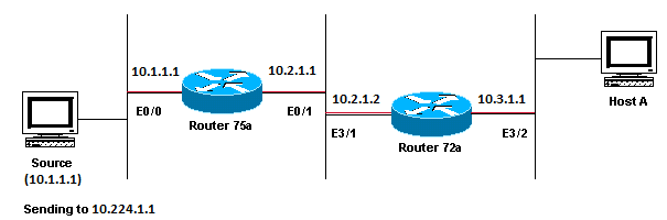 Network Diagram Example of Multicast RPF Failure
In this figure, multicast packets come into E0/0 of Router 75a from a server whose IP address is 10.1.1.1 and sends to group 224.1.1.1. This is known as an (S,G) or (10.1.1.1, 224.1.1.1).
Diagnose the Problem
Hosts directly connected to Router 75a receive the multicast feed, but hosts directly connected to Router 72a do not. First, enter the show ip mroute command in order to check activity on Router 75a. This command examines the multicast route (mroute) for the group address 224.1.1.1:
75a#show ip mroute 224.1.1.1
IP Multicast Routing Table
Flags: D - Dense, S - Sparse, C - Connected, L - Local, P - Pruned
       R - RP-bit set, F - Register flag, T - SPT-bit set, J - Join SPT
       M - MSDP created entry, X - Proxy Join Timer Running
       A - Advertised via MSDP
Timers: Uptime/Expires
Interface state: Interface, Next-Hop or VCD, State/Mode

(*, 224.1.1.1), 00:01:23/00:02:59, RP 0.0.0.0, flags: D
  Incoming interface: Null, RPF nbr 0.0.0.0
  Outgoing interface list:
    Ethernet0/1, Forward/Sparse-Dense, 00:01:23/00:00:00

(10.1.1.1, 224.1.1.1), 00:01:23/00:03:00, flags: TA
  Incoming interface: Ethernet0/0, RPF nbr 0.0.0.0
  Outgoing interface list:
    Ethernet0/1, Forward/Sparse-Dense, 00:01:23/00:00:00
Since the router runs PIM dense mode (you know it is dense mode because of the D flag), ignore the *,G entry and focus on the S,G entry. This entry tells you that the multicast packets are sourced from a server whose address is 10.1.1.1, which sends to a multicast group of 224.1.1.1. The packets come into the Ethernet0/0 interface and are forwarded out the Ethernet0/1 interface. This is a perfect scenario.
Enter the show ip pim neighbor command in order to see whether Router 72a shows the upstream router (75a) as a PIM neighbor:
ip22-72a#show ip pim neighbor
PIM Neighbor Table
Neighbor Address  Interface          Uptime    Expires   Ver  Mode
10.2.1.1           Ethernet3/1        2d00h     00:01:15  v2
From the show ip pim neighbor command output, the PIM neighborship looks good.
Enter the show ip mroute command in order to see whether Router 72a has good mroute:
ip22-72a#show ip mroute 224.1.1.1
IP Multicast Routing Table
Flags: D - Dense, S - Sparse, B - Bidir Group, s - SSM Group, C - Connected,
       L - Local, P - Pruned, R - RP-bit set, F - Register flag,
       T - SPT-bit set, J - Join SPT, M - MSDP created entry,
       X - Proxy Join Timer Running, A - Candidate for MSDP Advertisement,
       U - URD, I - Received Source Specific Host Report, Z - Multicast Tunnel
       Y - Joined MDT-data group, y - Sending to MDT-data group
Outgoing interface flags: H - Hardware switched, A - Assert winner
 Timers: Uptime/Expires
 Interface state: Interface, Next-Hop or VCD, State/Mode

(*, 224.1.1.1), 00:10:42/stopped, RP 0.0.0.0, flags: DC
  Incoming interface: Null, RPF nbr 0.0.0.0
  Outgoing interface list:
    Ethernet3/1, Forward/Dense, 00:10:42/00:00:00
    Ethernet3/2, Forward/Dense, 00:10:42/00:00:00

(10.1.1.1, 224.1.1.1), 00:01:10/00:02:48, flags:
  Incoming interface: Ethernet2/0, RPF nbr 0.0.0.0
  Outgoing interface list:
    Ethernet3/1, Forward/Dense, 00:01:10/00:00:00
    Ethernet3/2, Forward/Dense, 00:00:16/00:00:00

ip22-72a#
You can see from the show ip mroute 224.1.1.1 command that the incoming interface is Ethernet2/0, while Etheret3/1 is expected.
Enter the show ip mroute 224.1.1.1 count command in order to see if any multicast traffic for this group arrives to the Router 72a and what happens next:
ip22-72a#show ip mroute 224.1.1.1 count
IP Multicast Statistics
3 routes using 2032 bytes of memory
2 groups, 0.50 average sources per group
Forwarding Counts: Pkt Count/Pkts per second/Avg
Pkt Size/Kilobits per second
Other counts: Total/RPF failed/Other drops(OIF-null,
rate-limit etc)

Group: 224.1.1.1, Source count: 1, Packets forwarded:      0, Packets received: 471
  Source:      10.1.1.1/32, Forwarding: 0/0/0/0, Other: 471/471/0
ip22-72a#
You can see from the Other counts that traffic gets dropped due to RPF failure: total 471 drops, due to RPF failure – 471…
Enter the show ip rpf <source> command in order to see if there is an RPF error:
ip22-72a#show ip rpf 10.1.1.1
RPF information for ? (10.1.1.1)
  RPF interface: Ethernet2/0
  RPF neighbor: ? (0.0.0.0)
  RPF route/mask: 10.1.1.1/32
  RPF type: unicast (static)
  RPF recursion count: 0
  Doing distance-preferred lookups across tables
ip22-72a#
Cisco IOS® calculates the RPF interface in this way. Possible sources of RPF information are Unicast Routing Table, MBGP routing table, DVMRP routing table, and Static Mroute table. When you calculate the RPF interface, primarily administrative distance is used in order to determine exactly which source of information the RPF calculation is based on. The specific rules are:
-
All previous sources of RPF data are searched for a match on the source IP address. When you use Shared Trees, the RP address is used instead of the source address.
-
If more than one match route is found, the route with the lowest administrative distance is used.
-
If the administrative distances are equal, then this order of preference is used:
-
Static mroutes
-
DVMRP routes
-
MBGP routes
-
Unicast routes
-
-
If multiple entries for a route occur within the same route table, the longest match route is used.
The show ip mroute 224.1.1.1 command output shows the RPF interface is E2/0, but the incoming interface must be E3/1.
Enter the show ip mroute 224.1.1.1 command in order to see why the RPF interface is different from what was expected.
ip22-72a#show ip route 10.1.1.1
  Routing entry for 10.1.1.1/32
  Known via "static", distance 1, metric 0 (connected)
  Routing Descriptor Blocks:
  * directly connected, via Ethernet2/0
   Route metric is 0, traffic share count is 1
You can see from this show ip route 10.1.1.1 command output that there is a static /32 route, which makes the wrong interface to be chosen as RPF interface.
Enter some further debug commands:
ip22-72a#debug ip mpacket 224.1.1.1
*Jan 14 09:45:32.972: IP: s=10.1.1.1 (Ethernet3/1)
d=224.1.1.1 len 60, not RPF interface
*Jan 14 09:45:33.020: IP: s=10.1.1.1 (Ethernet3/1)
d=224.1.1.1 len 60, not RPF interface
*Jan 14 09:45:33.072: IP: s=10.1.1.1 (Ethernet3/1)
d=224.1.1.1 len 60, not RPF interface
*Jan 14 09:45:33.120: IP: s=10.1.1.1 (Ethernet3/1)
d=224.1.1.1 len 60, not RPF interface
The packets come in on E3/1, which is correct. However, they are dropped because that is not the interface the unicast routing table uses for the RPF check.
Note: Debugging packets is dangerous. Packet debugging triggers process switching of the multicast packets, which is CPU intensive. Also, packet debugging can produce huge output which can hang the router completely due to slow output to the console port. Before you debug packets, special care must be taken in order to disable logging output to the console, and enable logging to the memory buffer. In order to achieve this, configure no logging console and logging buffered debugging. The results of the debug can be seen with the show logging command.
Possible Fixes
You can either change the unicast routing table in order to satisfy this requirement or you can add a static mroute to force multicast to RPF out a particular interface, regardless of what the unicast routing table states. Add a static mroute:
ip22-72a(config)#ip mroute 10.1.1.1 255.255.255.255 10.2.1.1
This static mroute states that to get to the address 10.1.1.1 for RPF, use 10.2.1.1 as the next hop which is out interface E3/1.
ip22-72a#show ip rpf 10.1.1.1
RPF information for ? (10.1.1.1)
  RPF interface: Ethernet3/1
  RPF neighbor: ? (10.2.1.1)
  RPF route/mask: 10.1.1.1/32
  RPF type: static mroute
  RPF recursion count: 0
  Doing distance-preferred lookups across tables
The output of show ip mroute and debug ip mpacket looks good, the number of sent packets in the show ip mroute count increases, and HostA receives packets.
ip22-72a#show ip mroute 224.1.1.1
IP Multicast Routing Table
Flags: D - Dense, S - Sparse, C - Connected, L - Local, P - Pruned
       R - RP-bit set, F - Register flag, T - SPT-bit set, J - Join SPT
       M - MSDP created entry, X - Proxy Join Timer Running
       A - Advertised via MSDP
Timers: Uptime/Expires
Interface state: Interface, Next-Hop or VCD, State/Mode

(*, 224.1.1.1), 00:01:15/00:02:59, RP 0.0.0.0, flags: DJC
  Incoming interface: Null, RPF nbr 0.0.0.0
  Outgoing interface list:
    Ethernet3/1, Forward/Sparse-Dense, 00:01:15/00:00:00
    Ethernet3/2, Forward/Sparse-Dense, 00:00:58/00:00:00

(10.1.1.1, 224.1.1.1), 00:00:48/00:02:59, flags: CTA
  Incoming interface: Ethernet3/1, RPF nbr 10.2.1.1, Mroute
  Outgoing interface list:
    Ethernet3/2, Forward/Sparse-Dense, 00:00:48/00:00:00

ip22-72a#show ip mroute 224.1.1.1 count
IP Multicast Statistics
3 routes using 2378 bytes of memory
2 groups, 0.50 average sources per group
Forwarding Counts: Pkt Count/Pkts per second/Avg Pkt Size/Kilobits per second
Other counts: Total/RPF failed/Other drops(OIF-null, rate-limit etc)

Group: 224.1.1.1, Source count: 1, Packets forwarded: 1019, Packets received: 1019
  Source: 10.1.1.1/32, Forwarding: 1019/1/100/0, Other: 1019/0/0

ip22-72a#show ip mroute 224.1.1.1 count
IP Multicast Statistics
3 routes using 2378 bytes of memory
2 groups, 0.50 average sources per group
Forwarding Counts: Pkt Count/Pkts per second/Avg Pkt Size/Kilobits per second
Other counts: Total/RPF failed/Other drops(OIF-null, rate-limit etc)

Group: 224.1.1.1, Source count: 1, Packets forwarded: 1026, Packets received: 1026
  Source: 10.1.1.1/32, Forwarding: 1026/1/100/0, Other: 1026/0/0
ip22-72a#


ip22-72a#debug ip mpacket 224.1.1.1
*Jan 14 10:18:29.951: IP: s=10.1.1.1 (Ethernet3/1)
d=224.1.1.1 (Ethernet3/2) len 60, mforward
*Jan 14 10:18:29.999: IP: s=10.1.1.1 (Ethernet3/1)
d=224.1.1.1 (Ethernet3/2) len 60, mforward
*Jan 14 10:18:30.051: IP: s=10.1.1.1 (Ethernet3/1)
d=224.1.1.1 (Ethernet3/2) len 60, mforward
Router Does Not Forward Multicast Packets to Host Due to TTL Setting of Source
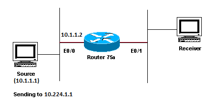
This section provides a solution to the common problem of IP multicast packets that are not forwarded because the Time To Live (TTL) value is decremented to zero. This is a common problem, as there are many multicast appplications. These multicast applications are designed primarily for the LAN usage, and thus set the TTL to a low value or even 1. Use this network diagram as an example.
 Multicast Applications Designed Primarily for the LAN Usage Example
Diagnose the Problem
In the previous figure, Router A does not forward packets from source(S) to Router B that is directly connected Receiver. Look at the output of the show ip mroute command on Router A in order to see the multicast routing state:
ROUTERA#show ip mroute
IP Multicast Routing Table
Flags: D - Dense, S - Sparse, C - Connected, L - Local, P - Pruned
       R - RP-bit set, F - Register flag, T - SPT-bit set, J - Join SPT
       M - MSDP created entry, X - Proxy Join Timer Running
       A - Advertised via MSDP
Timers: Uptime/Expires
Interface state: Interface, Next-Hop or VCD, State/Mode

(*, 224.0.1.40), 00:00:01/00:00:00, RP 0.0.0.0, flags: DJCL
  Incoming interface: Null, RPF nbr 0.0.0.0
  Outgoing interface list:
    Ethernet0/1, Forward/Sparse-Dense, 00:00:01/00:00:00

(*, 224.1.1.1), 00:00:02/00:02:57, RP 0.0.0.0, flags: D
  Incoming interface: Null, RPF nbr 0.0.0.0
  Outgoing interface list:
    Ethernet0/1, Forward/Sparse-Dense, 00:00:02/00:00:00
You can ignore the 224.0.1.40 in the output since all routers join this Auto-RP Discovery group. But there is no source listed for 224.1.1.1. In addition to "*, 224.1.1.1" you cannot see "10.1.1.1, 224.1.1.1".
Enter the show ip rpf command in order to see if it is a RPF issue:
ROUTERA#show ip rpf 10.1.1.1
RPF information for ? (10.1.1.1)
  RPF interface: Ethernet0/0
  RPF neighbor: ? (0.0.0.0) - directly connected
  RPF route/mask: 10.1.1.1/24
  RPF type: unicast (connected)
  RPF recursion count: 0
  Doing distance-preferred lookups across tables
From the output, it is not an RPF issue. The RPF check correctly points out E0/0 to get to the source IP address.
Check whether PIM is configured on the interfaces with the show ip pim interface command:
ROUTERA#show ip pim interface

Address          Interface          Version/Mode    Nbr   Query     DR
                                                    Count Intvl
10.1.1.2          Ethernet0/0        v2/Sparse-Dense  0    30     10.1.1.2
10.2.1.1          Ethernet0/1        v2/Sparse-Dense  2    30     10.2.1.2
The output looks good, so this is not the problem. Check whether the router recognizes any active traffic with the show ip mroute active command:
ROUTERA#show ip mroute active
Active IP Multicast Sources - sending >= 4 kbps
Based on the output, the router does not recognize any active traffic.
ROUTERA#debug ip mpacket
IP multicast packets debugging is on
Perhaps the Receiver does not send any Internet Group Management Protocol (IGMP) reports (joins) for group 224.1.1.1. You can check it with the show ip igmp group command:
ROUTERB#show ip igmp group
IGMP Connected Group Membership
Group Address    Interface            Uptime    Expires   Last Reporter
224.0.1.40       Ethernet1/1          00:34:34  never     10.2.1.2
224.1.1.1        Ethernet1/2          00:30:02  00:02:45  10.3.1.2
224.1.1.1 has been joined on E1/2, which is fine.
PIM dense mode is a flood and prune protocol, so there are no joins, but there are grafts. Since Router B has not received a flood from Router A, it does not know where to send a graft.
You can check to see if it is a TTL issue with the sniffer capture and also seen with show ip traffic command:
ROUTERA#show ip traffic
IP statistics:
  Rcvd:  248756 total, 1185 local destination
         0 format errors, 0 checksum errors, 63744 bad hop count
         0 unknown protocol, 0 not a gateway
         0 security failures, 0 bad options, 0 with options
The output shows 63744 bad hop counts. Each time you type this command, the bad hop count increases. This is a strong indication that the sender sends packets with a TTL=1, which Router A decrements to zero. This results in an increase of the bad hop count field.
Possible Fixes
In order to solve the issue, you need to increase the TTL. This is done at the application level on the Sender. For more information, refer to your multicast application instruction manual.
Once this is done, Router A looks like this:
ROUTERA#show ip mroute
IP Multicast Routing Table
Flags: D - Dense, S - Sparse, C - Connected, L - Local, P - Pruned
       R - RP-bit set, F - Register flag, T - SPT-bit set, J - Join SPT
       M - MSDP created entry, X - Proxy Join Timer Running
       A - Advertised via MSDP
Timers: Uptime/Expires
Interface state: Interface, Next-Hop or VCD, State/Mode

(*, 224.0.1.40), 01:16:32/00:00:00, RP 0.0.0.0, flags: DJCL
  Incoming interface: Null, RPF nbr 0.0.0.0
  Outgoing interface list:
    Ethernet0/1, Forward/Sparse-Dense, 01:16:32/00:00:00

(*, 224.1.1.1), 00:28:42/00:02:59, RP 0.0.0.0, flags: D
  Incoming interface: Null, RPF nbr 0.0.0.0
  Outgoing interface list:
    Ethernet0/1, Forward/Sparse-Dense, 00:28:42/00:00:00

(10.1.1.1, 224.1.1.1), 00:19:24/00:02:59, flags: TA
  Incoming interface: Ethernet0/0, RPF nbr 0.0.0.0
  Outgoing interface list:
    Ethernet0/1, Forward/Sparse-Dense, 00:19:24/00:00:00
This is the sort of output you want to see.
On Router B you see:
ROUTERB#show ip mroute
IP Multicast Routing Table
Flags: D - Dense, S - Sparse, C - Connected, L - Local, P - Pruned
       R - RP-bit set, F - Register flag, T - SPT-bit set, J - Join SPT
       M - MSDP created entry, X - Proxy Join Timer Running
       A - Advertised via MSDP
Timers: Uptime/Expires
Interface state: Interface, Next-Hop or VCD, State/Mode

(*, 224.0.1.40), 01:23:57/00:00:00, RP 0.0.0.0, flags: DJCL
  Incoming interface: Null, RPF nbr 0.0.0.0
  Outgoing interface list:
    Ethernet1/1, Forward/Sparse-Dense, 01:23:57/00:00:00

(*, 224.1.1.1), 01:19:26/00:02:59, RP 0.0.0.0, flags: DJC
  Incoming interface: Null, RPF nbr 0.0.0.0
  Outgoing interface list:
    Ethernet1/1, Forward/Sparse-Dense, 01:19:26/00:00:00
    Ethernet1/2, Forward/Sparse-Dense, 01:19:26/00:00:00

(10.1.1.1, 224.1.1.1), 00:17:46/00:02:59, flags: CTA
  Incoming interface: Ethernet1/1, RPF nbr 10.2.1.1
  Outgoing interface list:
    Ethernet1/2, Forward/Sparse-Dense, 00:17:46/00:00:00
Router Does Not Forward Multicast Packets Due to TTL Threshold of Router
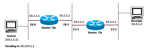
This section provides a solution to the common problem where the TTL threshold is set too low, so that IP multicast traffic does not reach the receiver. This network diagram is used as an example.
 TTL Threshold is too low so IP Multicast Traffic does not Reach the Receiver
Diagnose the Problem
In the previous figure, the Receiver does not receive multicast packets from the Source. There can be several routers between the source and Router 75a. First look at Router 75a, since it is directly connected to the Receiver.
ip22-75a#show ip mroute 224.1.1.1
IP Multicast Routing Table
Flags: D - Dense, S - Sparse, C - Connected, L - Local, P - Pruned
       R - RP-bit set, F - Register flag, T - SPT-bit set, J - Join SPT
       M - MSDP created entry, X - Proxy Join Timer Running
       A - Advertised via MSDP
Timers: Uptime/Expires
Interface state: Interface, Next-Hop or VCD, State/Mode

(*, 224.1.1.1), 00:32:05/00:02:59, RP 0.0.0.0, flags: DJC
  Incoming interface: Null, RPF nbr 0.0.0.0
  Outgoing interface list:
    Ethernet0/1, Forward/Sparse-Dense, 00:08:17/00:00:00

(10.1.1.1, 224.1.1.1), 00:01:02/00:01:57, flags: CTA
  Incoming interface: Ethernet0/0, RPF nbr 0.0.0.0
  Outgoing interface list:
    Ethernet0/1, Forward/Sparse-Dense, 00:01:02/00:00:00
The output shows Router 75a forwards packets out Ethernet0/1. In order to be absolutely sure Router 75a forwards the packets, turn on debug just for this source and multicast group:
ip22-75a#configure terminal
Enter configuration commands, one per line.  End with CNTL/Z.
ip22-75a(config)#access-list 101 permit udp host 10.1.1.1 host 224.1.1.1
ip22-75a(config)#end
ip22-75a#debug ip mpacket 101
IP multicast packets debugging is on for access list 101
ip22-75a#
*Jan 17 09:04:08.714: IP: s=10.1.1.1 (Ethernet0/0) d=224.1.1.1 len 60, threshold denied
*Jan 17 09:04:08.762: IP: s=10.1.1.1 (Ethernet0/0) d=224.1.1.1 len 60, threshold denied
*Jan 17 09:04:08.814: IP: s=10.1.1.1 (Ethernet0/0) d=224.1.1.1 len 60, threshold denied
The debug messages indicate that Router 75a does not forward the multicast packets because the TTL threshold has been reached. Look at the router configuration in order to see whether you can find the reason. This output shows the culprit:
interface Ethernet0/1
 ip address 10.2.1.1 255.255.255.0
 ip pim sparse-dense-mode
 ip multicast ttl-threshold 15
The router has a TTL threshold of 15, but this does not mean that anything greater than a TTL of 15 is not sent. Actually, the opposite is true. The application is sent with a TTL of 15. By the time it gets to Router 75a, the multicast packets have a TTL less than 15.
The ip multicast ttl-threshold <value> command means that any packets with a TTL lower than the specified threshold, in this case, 15, are not forwarded. This command is usually used in order to provide a border to keep internal multicast traffic from drifting out of the intranet.
Possible Fixes
Either remove the ip multicast ttl-threshold <value> command with the no form of this command, which reverts to the default TTL threshold value of 0, or lower the TTL threshold so that the traffic can pass.
Multiple Equal Cost Paths Result in Unwanted RPF Behavior
This section shows how equal cost paths to a multicast source can cause unwanted RPF behavior. It also describes how to configure IP multicast in order to avoid this behavior. This network diagram is used as an example.
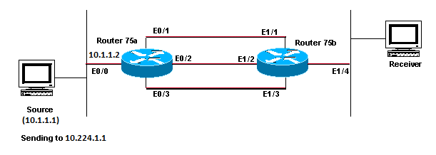 Equal Cost Paths to a Multicast Source Causes Unwanted RPF Behavior
Diagnose the Problem
In the figure, Router 75b has three equal cost paths back to the Source (10.1.1.1), and it chooses a link that you do not want to be its first choice as the RPF link.
When faced with multiple equal cost paths to a source, IP multicast chooses the interface that has a Protocol Independent Multicast (PIM) neighbor with the highest IP address as the incoming interface and then sends prunes to PIM neighbors on the other links.
Possible Fixes
In order to change the interface IP multicast chooses as its incoming interface, you can do one of these:
-
Only configure PIM on the interfaces that you want multicast to traverse, which means you lose multicast redundancy.
-
Change the subnets so the highest IP address is on the link you want to be the primary multicast link.
-
Create a static multicast route (mroute) that points out the preferred multicast interface, which means you lose multicast redundancy.
As an example, a static mroute is created.
Before you install a static mroute, you see in this output that the routing table has three equal cost routes for the source address 10.1.1.1. The RPF information indicates that the RPF interface is E1/3:
ip22-75b#show ip route 10.1.1.1
Routing entry for 10.1.1.1/24
  Known via "ospf 1", distance 110, metric 20, type intra area
  Redistributing via ospf 1
  Last update from 10.3.1.1 on Ethernet1/2, 00:26:21 ago
  Routing Descriptor Blocks:
  * 10.4.1.1, from 10.0.119.66, 00:26:21 ago, via Ethernet1/3
      Route metric is 20, traffic share count is 1
    10.2.1.1, from 10.0.119.66, 00:26:21 ago, via Ethernet1/1
      Route metric is 20, traffic share count is 1
    10.3.1.1, from 10.0.119.66, 00:26:21 ago, via Ethernet1/2
      Route metric is 20, traffic share count is 1

ip22-75b#show ip rpf 10.1.1.1
RPF information for ? (10.1.1.1)
  RPF interface: Ethernet1/3
  RPF neighbor: ? (10.4.1.1)
  RPF route/mask: 10.1.1.1/24
  RPF type: unicast (ospf 1)
  RPF recursion count: 0
  Doing distance-preferred lookups across tables

ip22-75b#show ip mroute 224.1.1.1
IP Multicast Routing Table
Flags: D - Dense, S - Sparse, C - Connected, L - Local, P - Pruned
       R - RP-bit set, F - Register flag, T - SPT-bit set, J - Join SPT
       M - MSDP created entry, X - Proxy Join Timer Running
       A - Advertised via MSDP
Timers: Uptime/Expires
Interface state: Interface, Next-Hop or VCD, State/Mode

(*, 224.1.1.1), 01:30:34/00:02:59, RP 0.0.0.0, flags: DJC
  Incoming interface: Null, RPF nbr 0.0.0.0
  Outgoing interface list:
    Ethernet1/4, Forward/Sparse-Dense, 01:30:34/00:00:00
    Ethernet1/1, Forward/Sparse-Dense, 01:30:35/00:00:00
    Ethernet1/2, Forward/Sparse-Dense, 01:30:35/00:00:00
    Ethernet1/3, Forward/Sparse-Dense, 00:24:22/00:00:00

(10.1.1.1, 224.1.1.1), 01:30:35/00:02:59, flags: CT
  Incoming interface: Ethernet1/3, RPF nbr 10.4.1.1
  Outgoing interface list:
    Ethernet1/1, Prune/Sparse-Dense, 01:30:35/00:02:32
    Ethernet1/4, Forward/Sparse-Dense, 01:30:35/00:00:00
    Ethernet1/2, Prune/Sparse-Dense, 00:24:22/00:02:42
After you configure the static mroute, you see in this output the RPF interface has changed to E1/1:
ip22-75b#configure terminal
Enter configuration commands, one per line.  End with CNTL/Z.
ip22-75b(config)#ip mroute 0.0.0.0 0.0.0.0 10.2.1.1
ip22-75b(config)#end

ip22-75b#show ip rpf 10.1.1.1
RPF information for ? (10.1.1.1)
  RPF interface: Ethernet1/1
  RPF neighbor: ? (10.2.1.1)
  RPF route/mask: 10.1.1.1/0
  RPF type: static mroute
  RPF recursion count: 0
  Doing distance-preferred lookups across tables

ip22-75b#show ip route 10.1.1.1
Routing entry for 10.1.1.1/24
  Known via "ospf 1", distance 110, metric 20, type intra area
  Redistributing via ospf 1
  Last update from 10.3.1.1 on Ethernet1/2, 00:26:21 ago
  Routing Descriptor Blocks:
  * 10.4.1.1, from 10.0.119.66, 00:26:21 ago, via Ethernet1/3
      Route metric is 20, traffic share count is 1
    10.2.1.1, from 10.0.119.66, 00:26:21 ago, via Ethernet1/1
      Route metric is 20, traffic share count is 1
    10.3.1.1, from 10.0.119.66, 00:26:21 ago, via Ethernet1/2
      Route metric is 20, traffic share count is 1

ip22-75b#show ip mroute 224.1.1.1
IP Multicast Routing Table
Flags: D - Dense, S - Sparse, C - Connected, L - Local, P - Pruned
       R - RP-bit set, F - Register flag, T - SPT-bit set, J - Join SPT
       M - MSDP created entry, X - Proxy Join Timer Running
       A - Advertised via MSDP
Timers: Uptime/Expires
Interface state: Interface, Next-Hop or VCD, State/Mode

(*, 224.1.1.1), 01:31:29/00:02:59, RP 0.0.0.0, flags: DJC
  Incoming interface: Null, RPF nbr 0.0.0.0
  Outgoing interface list:
    Ethernet1/4, Forward/Sparse-Dense, 01:31:29/00:00:00
    Ethernet1/1, Forward/Sparse-Dense, 01:31:30/00:00:00
    Ethernet1/2, Forward/Sparse-Dense, 01:31:30/00:00:00
    Ethernet1/3, Forward/Sparse-Dense, 00:25:17/00:00:00

(10.1.1.1, 224.1.1.1), 01:31:30/00:02:59, flags: CT
  Incoming interface: Ethernet1/1, RPF nbr 10.2.1.1, Mroute
  Outgoing interface list:
    Ethernet1/4, Forward/Sparse-Dense, 01:31:30/00:00:00
    Ethernet1/2, Prune/Sparse-Dense, 00:25:17/00:01:47
    Ethernet1/3, Prune/Sparse-Dense, 00:00:31/00:02:28
Why Does IP Multicast Not Load Balance Across All Available Equal Cost Paths?
This section provides a solution to the common problem of how to configure IP multicast in order to load balance across all available equal-cost paths. This network diagram is used as an example.
Note: Before you load split IP multicast traffic across equal-cost paths over a tunnel, configure CEF per-packet load balancing or else the GRE packets cannot be load balanced per packet. For other methods to load share in multicast environments, see Load Splitting IP Multicast Traffic over ECMP.
 Configure IP Multicast to Load Balance Across all Available Equal-Cost Paths
In the figure, Router 75b has three equal-cost paths back to the Source (10.1.1.1). You want to load-balance the multicast traffic across all three links.
Possible Fixes
As you saw in the Multiple Equal Cost Paths Result in Unwanted RPF Behavior section, Protocol Independent Multicast (PIM) only chooses one interface for the RPF check and prunes the others. This means load balancing does not occur. In order to load-balance, you need to remove PIM from the redundant links and create a tunnel between Router 75a and Router 75b. You can then load-balance at the link level, and IP runs over the tunnel.
These are the configurations for the tunnel.
| Router 75a |
|---|
interface Tunnel0 ip address 10.6.1.1 255.255.255.0 ip pim sparse-dense-mode tunnel source Ethernet0/0 tunnel destination 10.5.1.1 ! interface Ethernet0/0 ip address 10.1.1.2 255.255.255.0 ip pim sparse-dense-mode ! interface Ethernet0/1 ip address 10.2.1.1 255.255.255.0 ! interface Ethernet0/2 ip address 10.3.1.1 255.255.255.0 ! interface Ethernet0/3 ip address 10.4.1.1 255.255.255.0 |
| Router 75b |
|---|
interface Tunnel0 ip address 10.6.1.2 255.255.255.0 ip pim sparse-dense-mode tunnel source Ethernet1/4 tunnel destination 10.1.1.2 ! interface Ethernet1/1 ip address 10.2.1.2 255.255.255.0 ! interface Ethernet1/2 ip address 10.3.1.2 255.255.255.0 ! interface Ethernet1/3 ip address 10.4.1.2 255.255.255.0 ! interface Ethernet1/4 ip address 10.5.1.1 255.255.255.0 ip pim sparse-dense-mode ! ip mroute 0.0.0.0 0.0.0.0 Tunnel0 |
After you configure the tunnel, enter the show ip mroute command in order to see the multicast route (mroute) for the group:
ip22-75a#show ip mroute 224.1.1.1
IP Multicast Routing Table
Flags: D - Dense, S - Sparse, C - Connected, L - Local, P - Pruned
       R - RP-bit set, F - Register flag, T - SPT-bit set, J - Join SPT
       M - MSDP created entry, X - Proxy Join Timer Running
       A - Advertised via MSDP
Timers: Uptime/Expires
Interface state: Interface, Next-Hop or VCD, State/Mode

(*, 224.1.1.1), 02:40:31/00:02:59, RP 0.0.0.0, flags: D
  Incoming interface: Null, RPF nbr 0.0.0.0
  Outgoing interface list:
    Tunnel0, Forward/Sparse-Dense, 00:20:55/00:00:00

(10.1.1.1, 224.1.1.1), 02:40:32/00:03:29, flags: TA
  Incoming interface: Ethernet0/0, RPF nbr 0.0.0.0
  Outgoing interface list:
    Tunnel0, Forward/Sparse-Dense, 00:20:55/00:00:00

ip22-75b#show ip mroute 224.1.1.1
IP Multicast Routing Table
Flags: D - Dense, S - Sparse, C - Connected, L - Local, P - Pruned
       R - RP-bit set, F - Register flag, T - SPT-bit set, J - Join SPT
       M - MSDP created entry, X - Proxy Join Timer Running
       A - Advertised via MSDP
Timers: Uptime/Expires
Interface state: Interface, Next-Hop or VCD, State/Mode

(*, 224.1.1.1), 02:42:20/00:02:59, RP 0.0.0.0, flags: DJC
  Incoming interface: Null, RPF nbr 0.0.0.0
  Outgoing interface list:
    Tunnel0, Forward/Sparse-Dense, 00:22:53/00:00:00
    Ethernet1/4, Forward/Sparse-Dense, 02:42:20/00:00:00

(10.1.1.1, 224.1.1.1), 00:22:53/00:02:59, flags: CT
  Incoming interface: Tunnel0, RPF nbr 10.6.1.1, Mroute
  Outgoing interface list:
    Ethernet1/4, Forward/Sparse-Dense, 00:22:53/00:00:00
In order to check that the multicast data is load balanced equally across the three links, look at the interface data of Router 75a.
The incoming interface is 9000 bits/sec:
ip22-75a#show interface e0/0
.
.
  5 minute input rate 9000 bits/sec, 20 packets/sec
The three outgoing interfaces each show 3000 bits/sec:
ip22-75a#show interface e0/1
.
.
  5 minute output rate 3000 bits/sec, 7 packets/sec


ip22-75a#show interface e0/2
.
.
  5 minute output rate 3000 bits/sec, 7 packets/sec


ip22-75a#show interface e0/3
.
.
  5 minute output rate 3000 bits/sec, 7 packets/sec
When You Receive the IP Multicast "INVALID_RP_JOIN" Error Messages on the Router
This section provides solutions to the common problem of the IP multicast "INVALID_RP_JOIN" error message.
Diagnose the Problem - Part 1
This error messages is received on the Rendezvous Point (RP):
00:55:15: %PIM-6-INVALID_RP_JOIN: Received (*, 224.1.1.1) Join from 10.1.6.2 for invalid RP 10.1.5.4
00:56:15: %PIM-6-INVALID_RP_JOIN: Received (*, 224.1.1.1) Join from 10.1.6.2 for invalid RP 10.1.5.4
The Cisco IOS Software System Error Messages document explains what causes this error: a downstream PIM router sent a join message for the shared tree, which this router does not want to accept. This behavior indicates that this router allows only downstream routers join to a specific RP.
It is suspected it is filtering. You need to take a look at the configuration of the router:
interface Ethernet0/0
 ip address 10.1.5.4 255.255.255.0
 ip pim sparse-dense-mode
!
ip pim accept-rp 10.2.2.2 8
ip pim send-rp-announce Ethernet0/0 scope 15
ip pim send-rp-discovery scope 15
!
access-list 8 permit 224.0.0.0 0.255.255.255
What is the accept-rp statement in the configuration supposed to accomplish? In IP Multicast Routing Commands, it states that "to configure a router to accept Joins or Prunes destined for a specified RP and for a specific list of groups, use the ip pim accept-rp global configuration command. To remove that check, use the no form of this command."
When you remove the ip pim accept-rp command, the messages disappear. The command that causes the problem was found, but what if you want to keep that command in the configuration? You can permit the wrong RP address. Enter the show ip pim rp mapping command in order to see the correct RP address:
ip22-75a#show ip pim rp mapping
PIM Group-to-RP Mappings
This system is an RP (Auto-RP)
This system is an RP-mapping agent

Group(s) 224.0.0.0/4
  RP 10.1.5.4 (?), v2v1
    Info source: 10.1.5.4 (?), via Auto-RP
         Uptime: 01:00:48, expires: 00:02:07
Based on the output , 10.1.5.4 is the only RP learned via Auto-RP or otherwise. However, this router is only the RP for the groups 224.0.0.0/4. So, the pim accept-rp statement in the configuration is wrong.
Possible Fixes
The solution is to correct the IP address in the ip pim accept-rp statement as follows:
Change this statement:
ip pim accept-rp 10.2.2.2 8
To this:
ip pim accept-rp 10.1.5.4 8
You can also change the statement to accept what is in the auto-rp cache, and make certain that the access list (8 in this example) permits the necessary multicast group range. This is an example:
ip pim accept-rp auto-rp

access-list 8 permit 224.0.0.0 0.255.255.255
Diagnose the Problem - Part 2
This error message is seen on router2.
router2#
*Aug 12 15:18:17.891: %PIM-6-INVALID_RP_JOIN: Received (*, 224.0.1.40) Join from  0.0.0.0 for invalid RP 10.2.1.1
Check to see if router2 is the RP for group 224.1.1.1:
router2#show ip pim rp map
PIM Group-to-RP Mappings

Group(s) 224.0.0.0/4
  RP 10.1.1.1 (?), v2v1
    Info source: 10.1.1.1 (?), elected via Auto-RP
         Uptime: 00:21:26, expires: 00:02:24
router2#
The RP for 224.1.1.1 is 10.1.1.1.
Check if this is one of the interfaces of router2:
router2#show ip interface brief
Interface                  IP-Address      OK? Method Status                Protocol
Ethernet0/0                10.1.1.2         YES NVRAM  up                    up
Ethernet1/0                10.2.1.1         YES NVRAM  up                    up
Ethernet2/0                unassigned      YES NVRAM  administratively down down
router2#
Since router2 is not an RP, it must not have received this RP-Join packet. Check why the downstream router sent the Join to router2, while it must not:
router3#show ip pim rp map
PIM Group-to-RP Mappings

Group(s) 224.0.0.0/4
  RP 10.1.1.1 (?), v2v1
    Info source: 10.1.1.1 (?), elected via Auto-RP
         Uptime: 00:24:30, expires: 00:02:16
Group(s): 224.0.0.0/4, Static-Override
    RP: 10.2.1.1 (?)
router3#
As you see, router3 has statically configured RP information and points to router2, which is incorrect. This explains why router3 sends RP-Join to router2.
Possible Fixes
Either make router2 the RP for the group 224.1.1.1 or change the configuration on router3 so it refers to the correct RP address.
router3#show run | i rp
ip pim rp-address 10.2.1.1 override
router3#configure terminal
Enter configuration commands, one per line.  End with CNTL/Z.
router3(config)#no ip pim rp-address 10.2.1.1 override
router3(config)#exit
router3#
After the configuration on router3 is corrected, router3 refers to the correct RP address and the error message stops.
router3#show ip pim rp map
PIM Group-to-RP Mappings

Group(s) 224.0.0.0/4
  RP 10.1.1.1 (?), v2v1
    Info source: 10.1.1.1 (?), elected via Auto-RP
         Uptime: 00:30:45, expires: 00:02:02
router3#
Duplicate Multicast Packet Streams are Received
Cause 1
Duplicate multicast packets are received when two routers are configured in dense mode. In dense mode, the device periodically floods the stream. After flooding, it prunes off the interfaces where the steam is not wanted. The two routers also go through the assertion process and decide who is the forwarder. Every time the timers go off this happens, and until this process is complete, both routers forward the stream. This causes the application to receive duplicate multicast streams.
Possible Fix 1
This issue can be resolved if you have one of the routers configured for multicast routing and to configure the other router to be the RP in upstream. Configure it in order to convert the stream into sparse mode before the stream comes into the router. This can prevent duplicate packets from reaching the application. It is not a part of the networks responsibility to ensure that no duplicate packets ever reach an end host. It is a part of the responsibility of the application to handle duplicate packets and ignore unneeded data.
Cause 2
This issue can occur in Cisco Catalyst 6500 switches, which are configured for egress multicast replication mode and can be triggered by removal and re-insertion of any line cards [OIR]. After OIR, the Fabric Port Of Exit [FPOE] can be misprogrammed, which can cause packets to be directed to the wrong Fabric exit channel and sent to the wrong linecards. The result is that they are looped back to the Fabric and replicated multiple times when they exit on the correct linecard.
C6509#show mls ip multicast capability
Current mode of replication is Egress
Auto replication mode detection is ON

 Slot           Multicast replication capability
    1                        Egress
    2                        Egress
    3                        Egress
    4                        Egress
    5                        Egress
    6                        Egress
    7                        Egress
Possible Fix 2
As a workaround, change to ingress replication mode. During a change from egress- to ingress-replication mode, traffic interruptions can occur because the shortcuts are purged and reinstalled.
mls ip multicast replication-mode ingress
Upgrade the Cisco IOS software to a release not affected by Cisco bug ID CSCeg28814 in order to permanantly resolve the issue.

Note: Only registered Cisco users have access to internal Cisco tools and bug information.
Cause 3
This issue can also occur if the Receive Side Scaling (RSS) setting, on the end-hosts or servers, is disabled.
Possible Fix 3
The RSS setting facilitates faster transmission of data across multiple CPUs. Enable the RSS setting on the end-host or server.
Why are Multicast Packets Dropped?
Cause 1
It is possible that you see the excessive flushes and input packet drops on the interface(s) when Multicast traffic flows. You can check the flushes with the show interface command.
Switch#show interface gigabitethernet 1/0

!--- Output suppressed

MTU 1500 bytes, BW 1000000 Kbit, DLY 10 usec,
     reliability 255/255, txload 1/255, rxload 1/255
  Encapsulation ARPA, loopback not set
  Keepalive set (10 sec)
  Full-duplex, 1000Mb/s, media type is SX
  input flow-control is off, output flow-control is on
  Clock mode is auto
  ARP type: ARPA, ARP Timeout 04:00:00
  Last input 00:00:00, output 00:00:00, output hang never
  Last clearing of "show interface" counters never
  Input queue: 2/75/0/13370328 (size/max/drops/flushes); Total output drops: 0
  Queueing strategy: fifo
  Output queue: 0/40 (size/max)
  30 second input rate 195000 bits/sec, 85 packets/sec
  30 second output rate 1000 bits/sec, 1 packets/sec
  L2 Switched: ucast: 53056 pkt, 4728434 bytes - mcast: 235759386 pkt, 66914376970 bytes
  L3 in Switched: ucast: 8714263 pkt, 1815426423 bytes - mcast: 1081138213 pkt,
 438000092206 bytes mcast
  L3 out Switched: ucast: 4939256 pkt, 790351689 bytes mcast: 0 pkt, 0 bytes
     1326976857 packets input, 506833655045 bytes, 0 no buffer
     Received 1318209538 broadcasts, 0 runts, 0 giants, 1 throttles
     0 input errors, 0 CRC, 0 frame, 0 overrun, 0 ignored
     0 input packets with dribble condition detected
     31643944 packets output, 3124494549 bytes, 0 underruns
     0 output errors, 0 collisions, 1 interface resets
     0 babbles, 0 late collision, 0 deferred
     0 lost carrier, 0 no carrier
     0 output buffer failures, 0 output buffers swapped out
Possible Fix 1
You can set the SPT value as infinity for the interface where the excessive flushes are seen.
Configure this:
Switch(config-if)#ip pim spt-threshold infinity
Cause 2
When you use the ip igmp join-group <group-name> command on any interface(s), it does process switching. If multicast packets are process switched on any interface(s), it consumes more CPU as it mandates process switching of all packets to that group. You can run the show buffers input-interface command and check the abnormal size.
Switch#show buffers input-interface gigabitethernet 1/0

  Header DataArea  Pool Rcnt  Size Link  Enc    Flags          Input      Output

437C6EAC  8096AE4 Middl    1   434    7    1      280          Gi1/1        None
437C74B4  8097864 Middl    1   298    7    1      280          Gi1/1        None
437C98E4  809C964 Middl    1   434    7    1      280          Gi1/1        None
437CAAFC  809F1E4 Middl    1   349    7    1      280          Gi1/1        None
437CAE00  809F8A4 Middl    1   519    7    1      280          Gi1/1        None


!--- Output suppressed
Possible Fix 2
You can use the ip igmp static-group <group-name> command instead of the ip igmp join-group <group-name> command.
Note: Due to previous issues, it is possible that you see high CPU usage around 90 percent. CPU comes down to normal when you resolve them with these possible fixes.
Related Information
Revision History
| Revision | Publish Date | Comments |
|---|---|---|
3.0 |
22-May-2024
|
IP addressing correction |
2.0 |
26-May-2023
|
Recertification |
1.0 |
02-Dec-2013
|
Initial Release |
Contributed by Cisco Engineers
 Feedback
Contact Cisco
- Open a Support Case

- (Requires a Cisco Service Contract)