Securing the “Last Foot” in Distribution Automation White Paper
Available Languages
Bias-Free Language
The documentation set for this product strives to use bias-free language. For the purposes of this documentation set, bias-free is defined as language that does not imply discrimination based on age, disability, gender, racial identity, ethnic identity, sexual orientation, socioeconomic status, and intersectionality. Exceptions may be present in the documentation due to language that is hardcoded in the user interfaces of the product software, language used based on RFP documentation, or language that is used by a referenced third-party product. Learn more about how Cisco is using Inclusive Language.
MACsec can be implemented between a Cisco Catalyst IR1101 Rugged Router and a SEL-651R recloser, so network traffic associated with distribution automation is cryptographically secured within the utility cabinet.
Authors: Pete Kavanagh (Cisco), Colin Gordon (SEL), Jon Vargas (SEL)
This paper describes a solution for the “last foot” problem, which is a well-known cybersecurity vulnerability that worldwide electric distribution system owners and operators often confront and ask manufacturers to mitigate via a cryptographic solution. Here the authors investigate the central concept of the “last foot” problem, examine the trade-offs and requirements for selecting the best approach to solving that problem, and introduce a long-lived solution in the form of IEEE 802.1AE Media Access Control Security (MACsec) and the MACsec Key Agreement (MKA) portion of 802.1X Port-Based Network Access Control.
What is an electric distribution system?
Electrical energy systems are critical infrastructure built to supply a safe, reliable, and economical flow of electric energy to businesses, residences, and other critical infrastructure elements. Well-functioning energy systems themselves require reliable components that are available when called to act, with one example being the recloser control.
A recloser control mitigates the dangers of unusually high electric currents (called a fault condition) by interrupting the flow of electricity on one or more distribution electric lines (called clearing a line). The recloser control performs this process by “tripping” a recloser, which is an automatic electric switch or breaker engineered for electric distribution voltages. The recloser control detects abnormal system conditions (overcurrent, over- and under-voltage situations, etc.) using current and voltage transformers or sensors. The recloser control must act in a manner that is both dependable and secure (hereafter referred to as protection security so as not to conflate protection-based security with cybersecurity). Dependability requires maximum sensitivity and response times fast enough to detect and clear all faults quickly with very low probability of a failure to trip, and protection-security goals require maximum selectivity with response times slow enough to minimize the probability of an unwanted trip on an unfaulted distribution line. This combination of dependability and protection security is meant to maximize the overall reliability of the electrical power system, which is reflected in industry reliability indices such as Momentary Average Interruption Frequency Index (MAIFI), System Average Interruption Frequency Index (SAIFI), and so on.
Thus the primary duty of the recloser control is to detect electrical fault conditions on electrical distribution systems and prevent them from endangering human beings, destroying valuable power system equipment, or causing fires—all of which could result in blackouts that could cause property damage or the loss of electricity for thousands of people who rely on the power provided by any one distribution line.
Recloser controls reside in secure, tough metal cabinets simply called recloser control cabinets. Engineers design these cabinets to be hardened against the elements of the terrain in which they must operate, and they contain everything needed to enable the operation of the recloser control. Recloser control cabinets contain radios for communication, gateways for cybersecurity and physical tamper-awareness functions, a power module with capacitors necessary to operate a recloser and batteries to power the recloser control and communications devices in case of primary power failure, and any auxiliary power supplies necessary to convert power outputs to necessary levels for devices in the cabinet.
Electric Distribution network communications
Designers of electrical distribution communications network systems often implement a hub-and-spoke architecture in which one or more secured metal cabinets communicate with a central location (a distribution substation or control center) over a Wide-Area Network (WAN). This WAN usually involves a wireless communication medium, which can be a public routable network, such as a cellular network. The figure below shows an example of a “spoke” connected to the central “hub” of a system with a hub-and-spoke architecture.
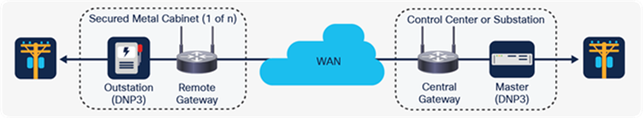
One spoke of a system with hub-and-spoke architecture
Typical traffic flows between a Supervisory Control And Data Acquisition (SCADA) master and an outstation recloser control include engineering access functions in the form of Telnet, HTTP, FTP - and SCADA functions in the form of Distributed Network Protocol 3 (DNP3), and Modbus. Other instrumental traffic flows include timing protocols such as Network Time Protocol (NTP), and Precision Time Protocol (PTP), as well as Address Resolution Protocol (ARP) for initializing IP transport. A growing number of Distribution Automation (DA) architectures include peer-to-peer fiber or mesh wireless connections between recloser controls, but these are not as prevalent as cellular connections, with cellular having both public and private network options.
Typical modern DA cabinet architecture
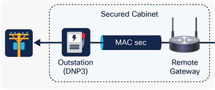
The primary vulnerability of geographically dispersed recloser control cabinets is physical in nature. It is difficult to properly secure recloser control cabinets and offer boots-on-the-ground response times fast enough to adequately respond to live tamper scenarios. System owners generally answer these concerns with precautions such as additional physical hardening procedures, designs, and locks and additional digital precautions such as communications-securing gateways that are placed inside the locked enclosures (as alluded to above) to provide filtered, cryptographically secure Ethernet transport to and from cellular networks. However, one well-known vulnerability—the so-called “last foot” vulnerability—involves what is usually a standard Ethernet cable between the cabinet gateway and the recloser control that attackers can disconnect and abuse, as shown in the figure below.
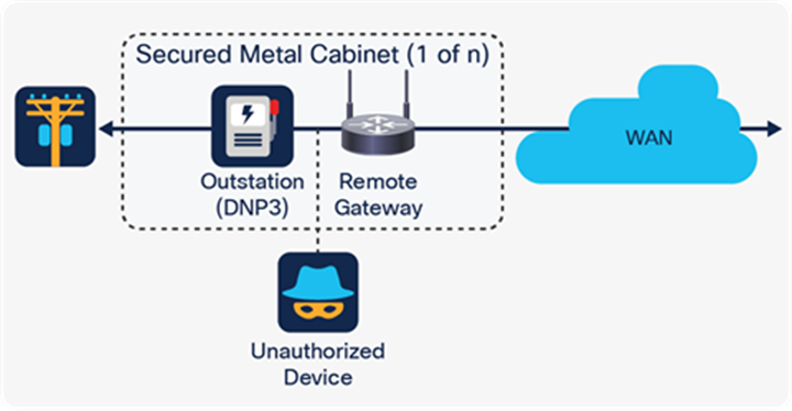
The “last foot” vulnerability
Were an attacker to compromise this “last foot” of communication cable, he or she would be able to connect to and communicate with the recloser control itself, perhaps for the purpose of issuing false recloser trip commands (which would open the reclosing element) or stealing data such as device secrets passing over the wire. Further, in some circumstances an attacker who physically compromises the recloser control cabinet could obtain access to the SCADA master residing in a distribution substation or perhaps at a centralized distribution control center.
Electrical distribution owners and operators generally add security gateway devices that encrypt data ingressing from wireless networks using protocols such as IP Security (IPsec) or Transport Layer Security (TLS). However, these bump-in-the-wire (BITW) security provisions, where the communications flows are decrypted on ingress from the wireless network at the gateway, still leave the last-foot vulnerability unmitigated. (Note that BITW here is from the perspective of the SCADA communication and its serial heritage, rather than being related to IP networking).
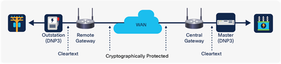
Common bump-in-the-wire solutions
System owners and operators have increasingly called for the implementation of some variant of embedded Ethernet-based cryptographic functionality directly into the recloser control so as to mitigate the “last foot” vulnerability and prevent attacks against both the recloser control itself and the remote SCADA master. A cryptographic solution between the cabinet gateway and the recloser control that protects communications would serve to prevent an attacker from inserting an unauthenticated device into the in-cabinet network. However, which cryptographic solution is best, and how do we determine the criteria for a solution?
Setting out criteria for the solution
Determining the best cryptographic solution for recloser controls must start with an examination of the nature of the device itself and its purpose in the power distribution system. Much of this has already been discussed. However, a better understanding of the manufacturing constraints associated with the recloser control will provide additional clarity.
Recloser controls are intrinsically bound up with well-functioning energy distribution systems and ultimately require direct interaction with physical elements (such as reclosers, inputs, outputs, and power lines) that are geographically fixed and thus cannot simply be duplicated or migrated while the electrical distribution system provides a continuous, uninterrupted energy supply. Because of this, recloser controls generally have lifespans of decades and naturally require greater care when undergoing maintenance operations such as firmware upgrades. Manufacturers of critical energy system elements are cognizant of the demanding nature of this lifespan requirement and therefore purposely build those elements to perform a specific minimal and rigidly defined set of functions consistently and reliably, with the goal of reducing firmware churn. The technology that goes into the recloser control thus needs to be suitable for this service lifespan or risk more frequent maintenance cycles to update the equipment. Each “truck roll” made unnecessary by reducing superfluous code or features saves the distribution system owner $1000 to $2000 per firmware update event.
Therefore, for the sake of safety, reliability, and operational cost, some technology in energy systems may be decades behind current communications and enterprise technology.
The following is a list of some considerations and challenges related to applying more enterprise-oriented cryptographic security controls in distribution energy systems1.
Frequent changes to standards and best practices
Cybersecurity and cryptographic standards frequently change based on external factors such as the availability of new cryptanalysis tools, the increase in computational power available to threat actors, and the introduction of novel attack techniques, among others. These frequent cryptographic standard changes, by both private industry groups and government entities, are problematic for energy system environments. The lag time between a standard’s ratification and its implementation by energy system manufacturers, and subsequently by system owners, can be considerable due in part to the constraints of cyber-physical systems already outlined in this document. As a result, firmware upgrades may already be out of date according to current cryptographic standards when upgrades are deployed within the energy system environment.
Firmware maintenance burden
Recloser controls have evolved from purely electromechanical devices to devices with adjustable analog electronics, and to microprocessor-based relays with adjustments and protection schemes in code. As communications networks have grown to include them, design choices made to provide security for this new communications functionality can require additional maintenance and introduce a higher chance of firmware flaws that are unrelated to their critical functionality. Consequently, the number of lines of code (LoC) has progressed from a minuscule 40,0002 in early protection relays to over 600,000 today, with only 7% of that count involved directly with protective relay functions. OpenSSL (the popular open-source package for TLS implementations) currently contains over 500,000 LoC3.
Loss of situational awareness
IT-oriented cryptographic protocols (such as TLS, Secure Shell [SSH], and IPsec) focus on providing end-to-end confidentiality first and foremost, as well as integrity and authenticity controls for communication links to keep out intruders and ensure that authorized users who are trusted to be on the system can work securely. The protocols ensure that the information traversing the connection cannot easily be read or captured by anyone (or anything) on the network. Confidentiality is such a critical requirement of TLS 1.3 that the standard does not allow the use of “null-cipher” suites that remove confidentiality while keeping integrity and authenticity controls.4
Required end-user expertise
The IT departments at many organizations already have security and cryptographic expertise for managing and securing large numbers of users, which is due to the variety of ecosystems based on public-key infrastructure (PKI). OT units within smaller energy organizations (such as public utilities or electric cooperatives) without embedded IT experience can find it challenging to know how to configure cryptographic systems in OT environments. OT system owners may prefer to avoid patch mandates and vulnerability findings coming from the IT department by not enabling security features, but IT-oriented cryptography can often force the hands of OT system owners. At the end of the day OT systems need to minimize patches. Allowing IT control over OT assets also may impose IT helpdesk processes on critical energy systems and devices. This IT-OT divide is often handled by dividing IT and OT equipment into separate physical zones, with IT security governance falling on the communications gateway equipment at the perimeter location and OT owning the critical devices within the energy system.
The difficulty of key management in energy systems
Security key management in energy systems is notoriously tricky because manual key management has the same issues as patching, and the other choice, automated key management, increases complexity and attack surface. The outcome is that, typically, cryptographic keys will not change after system commissioning for the lifetime of the device. There are National Institute of Standards and Technology (NIST) standards (such as NIST SP800-57)5 that contain recommendations for key management timelines and lifecycles. However, due to the management lifecycles of competing standards or difficulties associated with key management, these recommendations are rarely followed6.
Manual rekeying operations for BITW-encrypting communication gateways are often difficult to execute even by trained operations personnel and often require coordination across geographical regions, including notifications to upstream SCADA control operators of expected downtime.
Hardware requirements
Modern cryptographic protocols often rely on special hardware, including cryptographic accelerators, to meet performance goals. Embedded devices, particularly legacy intelligent electrical devices (IEDs), were built without cryptographic accelerators, so many modern cryptographic methods may prove infeasible or may quickly become so as standards evolve. For devices such as recloser controls, their primary designed functions do not evolve in this way, and they will be capable of reliably performing those functions (such as fault protection) for much longer7. Many legacy systems also lack the required entropy (randomness) sources to produce strong cryptographic keys. A common approach to this challenge from enterprise manufacturers is to add specialized cryptographic hardware to devices and systems for these kinds of functions8,9,10, which is an excellent strategy for hardware with a lifespan of three to seven years. However, this expected cryptographic platform obsolescence does not suit critical protection devices with service lifetimes of decades.
Summary of cryptographic criteria
Critical infrastructure manufacturers wanting to implement cryptography in energy system components should be aware of the following considerations:
● Use standards that are not subject to frequent changes or that are designed for infrastructure with different mission requirements that still meet necessary cybersecurity objectives.
● Simplify designs to minimize the effects of expanded LoC and maintenance requirements associated with additional features.
● Minimize the impact of cryptographic security controls on critical time-sensitive protection protocols.
● Use cryptographic implementations for data in motion that support network visibility requirements and maximize situational awareness.
● Choose technologies with lifespans suited to application in devices with long service lives.
Having discussed energy systems in general, we believe IEEE 802.1AE MACsec balances the need for “last foot” cybersecurity mitigations and the reliability, availability, and longevity requirements of recloser controls in distribution system environments.
With MACsec on the LAN, between the outstation device and the remote gateway, it is also the gateway’s job to maintain data encryption on the WAN; typically this is done with an IPsec-secured tunnel that has natively Open Systems Interconnection (OSI) Layer 3 traffic and tunneled Layer 2 traffic within. The Cisco® Catalyst® 1101 Rugged Router (IR1101) effectively manages two back-to-back encrypted connections: one LAN-facing toward the Schweitzer Engineering Laboratories (SEL) reclose control, the other WAN-facing.
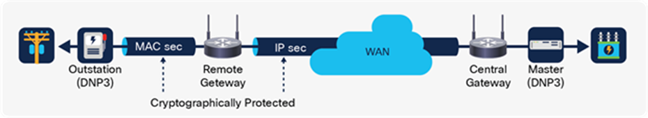
IPsec-secured tunnel configuration
Based on all prior considerations and criteria, a combination of IEEE 802.1AE-2018 MACsec and IEEE 802.1X-2010 Clause 9 MKA protocol were chosen as the solution. Below are the details of the solution.
Technical details of MACsec and MKA
IEEE 802.AE MACsec
IEEE 802.1AE MACsec is a nonroutable “hop-by-hop” data plane cryptographic protocol that protects Ethernet frames starting at the data-link layer (OSI Layer 2). The MACsec protocol provides the following security attributes:
● Confidentiality: Obfuscation of the Ethernet frame’s data payload through encryption (note that although confidentiality is optional in the standard, the Cisco and SEL interoperability mandates that all sessions be encrypted and authenticated).
● Integrity: Prevention of manipulation of any section of the Ethernet frame using an Integrity Check Value (ICV).
● Authenticity: Providing proof of the identity of the hosts on the LAN and prevention of spoofing attacks with symmetrical encryption keys.
● Replay prevention: Mitigation of replay attacks using consecutive packet numbers (PNs).
MACsec functions by taking the original Ethernet frame and adding two components to it: a MACsec security tag header and an ICV trailer. The figure below shows an example of a normal Ethernet II frame.
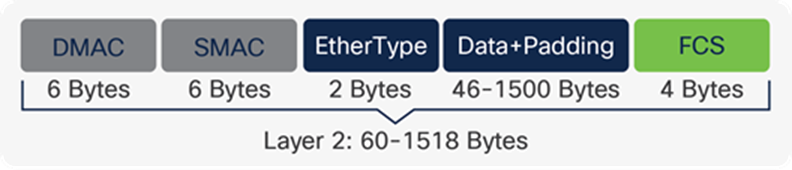
Ethernet II frame
The following figure shows the normal Ethernet II frame with the addition of MACsec.
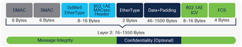
Ethernet II frame with 802.1AE MACsec header and trailer
By default, MACsec uses Advanced Encryption Standard with Galois/Counter Mode with a 128-bit key (AES-GCM-128). AES-GCM is an Authenticated Encryption with Additional Data (AEAD) cipher that performs both encryption and authentication of the original data using a single symmetrical key. AEAD ciphers are useful for MACsec as they enable the implementing device to secure all parts of an Ethernet frame. This means that MACsec can optionally encrypt the data payload and still provide integrity and replay protection for the entire Ethernet frame, including the original source and destination MAC addresses (which are not encrypted). AEAD ciphers also allow for special treatment of virtual LAN (VLAN) headers, which can optionally be secured.
Cryptographic keys
When hosts on a LAN want to securely communicate with each other using MACsec, they use a symmetrical Secure Association Key (SAK) to secure the connection. To prevent packet loss when transitioning to a new SAK, each device must be able to support two SAKs simultaneously, each distinguished by an Association Number (AN), which ranges from 0 to 3 All frames between two hosts (bidirectionally) can then be secured with MACsec, with the assumption that no attacker is able to communicate successfully with the other hosts on the network without knowing the correct SAK.
MACsec on a point-to-point LAN
Edge device and host communicating via MACsec
For two MACsec-supporting devices to communicate, they must be configured with the following:
● One or more SAKs along with their respective AN used to distinguish the keys
● A cryptographic cipher, which for IEEE 802.1AE defaults to AES-GCM-128
● A Confidentiality Offset (CO), which indicates whether none, some, or all of the Ethernet payload is to be encrypted
Scalability, maintainability, and ease of use
A MACsec solution is simple and powerful in that it mitigates the last-foot vulnerability. However, a MACsec-alone implementation has several concerns related to maintainability and ease of use:
● More than two MACsec hosts: In LANs with more than two hosts, it quickly becomes unscalable to program keys and the unique secure channel identifiers (SCIs) used in the MACsec header of each device. The complexity for a large LAN scenario would be exponential, since SCIs would need to be programmed for each device on the LAN that wants to communicate with the other.
● SAK rotation: SAKs need to be retired after 2^32 packets due to the use of the PN as an initialization vector (IV). The reuse of IVs due to PN rollover after 2^32 frames would break the security of AES-GCM. Networks running simple DNP for SCADA and some intermittent engineering access traffic would not see large numbers of packets. However, there is still a question of security standards or policies that require key changes at some regular interval.
● Commissioning: While a point-to-point configuration is simpler than TLS or IPsec (using SAKs, ANs, and COs), there is still an opportunity to simplify the solution.
The quest for greater scalability, maintainability, and ease of use leads to the second part of the solution: the MKA protocol.
IEEE 802.1X-2010 Clause 9: MACsec Key Agreement (MKA)
MKA is a control plane protocol that facilitates and automates the commissioning, management, and scalability of MACsec on a LAN. MKA provides the following ease-of-use attributes:
● Network discovery: Hosts can discover other MKA-supporting devices attached to the same LAN.
● Mutual authentication: Hosts can confirm mutual possession of a connectivity association key (CAK) and prove a past mutual authentication.
● Key management: MKA automatically generates new SAKs for all authorized MACsec hosts joining a LAN and rotates SAKs when they near expiration. MKA can also distribute new CAKs to ensure that CAKs are refreshed on a regular basis.
● MACsec parameter management: MKA enables the automatic creation of SCIs and can be used to facilitate the synchronization of the cipher suites and COs used by all authorized MACsec hosts.
● Bounded receive delay: MKA can guarantee that a frame will not be delivered after a known bounded time (typically two seconds) with a lowest-acceptable packet number (LPN).
MKA automates most of the commissioning and management overhead of the MACsec protocol for all authorized hosts on a LAN. Devices implementing MKA will act either as an MKA key server (a device that generates and distributes keys) or as an MKA client (a device that receives keys).
The MKA protocol is an extension to the IEEE 802.1X Port-Based Network Access Control (NAC) standard and is specific to MACsec implementations. Two or more MACsec hosts may use MKA to “advertise” and synchronize with each other on a LAN through an 802.1X-specific multicast MAC address. During the synchronization process, the hosts exchange details and negotiate who becomes the MACsec key server on the LAN. When the negotiation is complete, the MACsec key server is responsible for automating SAK distribution to authorized members, synchronizing MACsec cipher suite details, and rotating SAKs when their expiration nears, or automatically based on a time interval (such as every hour).
Cryptographic keys
All hosts wanting to use MKA with each other require a CAK with an associated connectivity association key name (CKN). Using the CAK with the AES Cipher-Based Message Authentication Code (AES-CMAC) cipher, the MKA protocol authenticates hosts on the LAN and securely distributes encrypted SAKs to MACsec-supporting devices. Once all necessary SAKs are distributed, hosts can securely communicate with each other using MACsec.
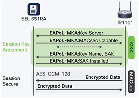
Interaction between MKA (control plane) and MACsec (data plane)
MKA on the LAN
For two or more MACsec and MKA-supporting devices to be able to communicate, they must be configured with a CAK and an associated CKN.
● MACsec is a fairly simple protocol, having undergone few standard updates since its publication in 2006.
● Pre-shared key (PSK) mode is simple. There is no PKI and X.509 handling on the SEL recloser control side. Key management is greatly simplified; the Catalyst IR1101 acts as the MACsec key server.
● It is interoperable with network interface devices (NIDs) when in integrity-only mode.
● The user commissioning process is minimal on the SEL recloser control, being a three-step process; MACsec can be enabled on the Catalyst IR1101 remotely via the WAN connection.
● Existing SEL recloser devices are firmware-upgradable to support MACsec.
● The Catalyst IR1101 router is firmware-upgradable to support MACsec.
● It covers engineering access functions in the form of Telnet, HTTP, FTP - and SCADA functions in the form of Distributed Network Protocol 3 (DNP3), and Modbus. It also includes Network Time Protocol (NTP), as well as Address Resolution Protocol (ARP) for initializing IP transport.
Cisco is releasing 802.1AE MACsec support on the Catalyst IR1101 router in the fall of 2022, with interoperability, based on AES-GCM-128 MACsec and PSK-mode MKA, with SEL, who is releasing it in the SEL-651R-2 and SEL-651RA in the summer of 2022.
When combined, the Cisco and SEL solution successfully secures the “last foot” within the utility cabinet, enabling customers to have strong encryption that is truly end to end across their critical infrastructure.
For more information on the Cisco Catalyst 1101 Rugged Router, visit cisco.com/go/ir1101.
For more information on SEL reclosers, visit https://selinc.com/products/651R/.
Please talk with Cisco and SEL at Distributech 2022 to gain a further understanding of the solution.