Dräger Patient Monitoring with Cisco Catalyst Wireless Deployment Guide
Available Languages
Bias-Free Language
The documentation set for this product strives to use bias-free language. For the purposes of this documentation set, bias-free is defined as language that does not imply discrimination based on age, disability, gender, racial identity, ethnic identity, sexual orientation, socioeconomic status, and intersectionality. Exceptions may be present in the documentation due to language that is hardcoded in the user interfaces of the product software, language used based on RFP documentation, or language that is used by a referenced third-party product. Learn more about how Cisco is using Inclusive Language.
This document provides design considerations and deployment guidelines for the Dräger Infinity monitoring solution within the Cisco® Catalyst wireless network infrastructure.
Note: Support for Dräger products should be obtained directly from Dräger support channels. Cisco Technical Assistance Center (TAC) staff are not trained to resolve problems related to Dräger products.
This guide addresses the configuration parameters that are particular to Dräger Infinity monitoring devices in a managed wireless architecture. Basic network design, wired multicast recommendations, and basic protocol design concepts are beyond the scope of this document. To get the most out of this deployment guide, you should have a fundamental understanding of network architecture and protocol design concepts.
We recommend that you read and become familiar with the terms and concepts presented in the following Cisco documents:
● Wireless considerations in healthcare environments: https://www.cisco.com/c/en/us/solutions/industries/healthcare.html
● Cisco Catalyst 9800 Series multicast configuration: https://www.cisco.com/c/en/us/td/docs/wireless/controller/9800/config-guide/b_wl_16_10_cg/wireless-multicast.html
● Cisco Catalyst 9800 Series basic configuration (video): https://www.cisco.com/c/en/us/td/docs/wireless/controller/9800/videos/Basic-Configuration-of-Cisco-Catalyst-9800-Series-Wireless-Controller.html
These documents are available at Cisco.com with the proper login permissions.
Wireless patient monitors are not a new phenomenon. Patient telemetry has been done over dedicated wireless channels since the early 1970s, first using analog transmission schemes and then transitioning to digital in the 1990s. The advent of 802.11-compatible wireless patient monitors has unlocked the many advantages of using a standard, off-the-shelf wireless technology but has presented some implementation challenges due to the life-critical nature of the application.
A dropped packet or two may slow down a file transfer or webpage access or may result in a garbled word in a wireless voice-over-IP (VoIP) call, but a lost packet in a patient monitoring application may delay alerting nursing staff to an urgent condition, with the potential of serious patient injury. With this understanding, a strong radio policy is critical for such applications running in an 802.11 environment, where packet loss and latency must be kept to a minimum.
This guide provides design and deployment guidelines to help ensure a successful and safe deployment of the Dräger Infinity monitoring solution using the Cisco Catalyst wireless network infrastructure.
Note: The Dräger Infinity Monitoring solution recommends Cisco IOS-XE 17.3.2 Controller software or newer. Check with your Dräger Service Team for the most up-to-date information on the latest supported hardware/software versions.
The following sections provide an overview of the Dräger medical devices that can be integrated into a Cisco Catalyst Wireless Network.
Infinity bedside patient monitoring solution
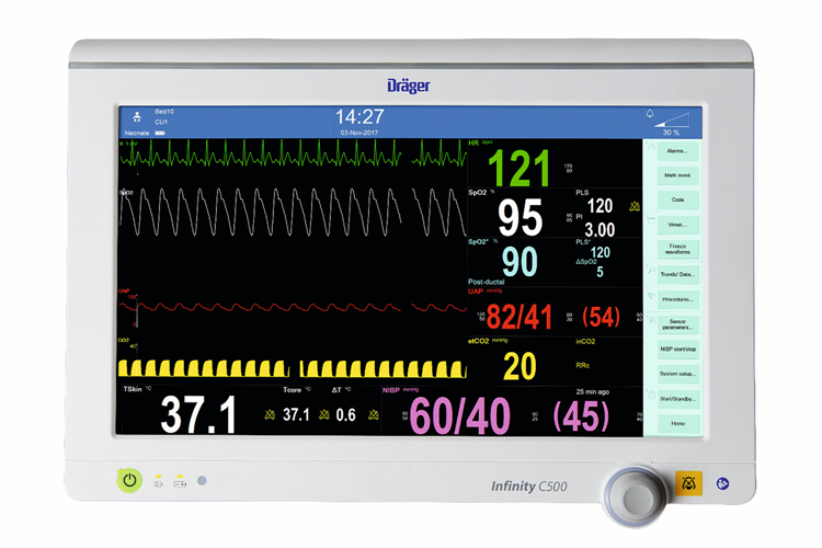
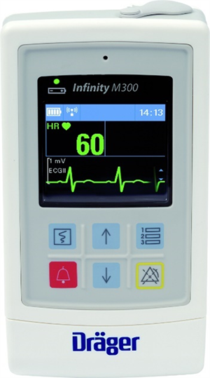
Infinity bedside patient monitors provide comprehensive patient monitoring that includes multiple-lead ECG, oxygen saturation, respiration, dual temperature, cardiac output, multiple invasive pressures, noninvasive blood pressure, and arrhythmia classification. Figure 1 shows some of the information provided by one of the patient monitoring devices.
© Drägerwerk AG and Co. KGaA, Lubeck. All rights reserved.
Infinity bedside patient monitor example
A wide range of sizes and styles—including the Infinity Delta and M540— enable customers to tailor the system to departmental needs. These monitors bring critical information from other bedside devices to the patient monitor via the Infinity Docking Station to help clinicians make faster patient assessments. The monitors provide maximum reliability, decreased downtime, reduced need for spare parts, and lower support costs.
The Infinity central monitoring solution gathers and displays information from the Infinity bedside monitors and patient-worn Infinity devices. Up to 32 patients can be simultaneously monitored and displayed on each Infinity Central Station.
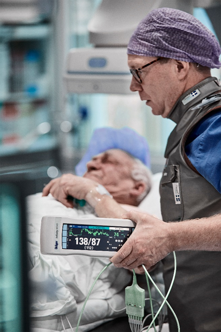
The patented Pick and Go flexibility lets Infinity monitors move with the patient. When undocked, the patient monitor switches to wireless mode and continuously transmits vital data signs back to the central monitor systems. The ability to monitor patients during transport throughout the healthcare facility has become an important requirement for caregivers.
© Drägerwerk AG and Co. KGaA, Lubeck. All rights reserved.
Infinity monitors moving with a patient
Technical aspects of Infinity bedside monitoring solutions
The Infinity bedside monitoring solution uses standard IP multicast packets for more than 90 percent of its I/O. Devices are both IP multicast transmitters and receivers, which helps ensure the exchange of information with all connected devices of a defined group, called a Monitoring Unit (MU). To prevent flooding of this traffic, both the wired and wireless portions of the network must be configured for Internet Group Management Protocol (IGMP) to constrain the multicast traffic. Infinity bedside monitors constantly transmit packets at approximately 100 kbps in both wired and wireless mode.
Within a monitoring unit, four common multicast streams are created and shared by all Infinity devices in the MU, as both transmitters and group members. In addition, each bedside monitor transmits its unique multicast stream of waveform pixel and vital-signs data that an Infinity Central Station uses for active display. That stream can be requested on another bedside monitor in the same MU by a clinician using the remote view feature. The waveform display occupies the lower portion of the local monitor’s screen. In this case, the multicast data flows directly between the two bedside monitors and is not routed through the Infinity Central Station.
Table 1 shows an example of the multicast addresses generated in a single monitoring unit with three bedside devices. It is highly recommended that you create an overview of utilized multicast addresses when deploying a patient monitoring installation.
Table 1. Example of multicast addresses for patient monitoring
| Multicast addresses for monitoring unit 5 |
|
| Name service |
224.127.5.255 |
| Alarm group service |
224.127.5.254 |
| Time service |
224.127.5.253 |
| Alarm group service for ventilators |
224.127.5.252 |
| Patient data stream (first Infinity bedside monitor) |
224.0.5.1 |
| Patient data stream (second Infinity bedside monitor) |
224.0.5.2 |
| Patient data stream (Nth Infinity bedside monitor) |
224.0.5.N |
Infinity M300 patient-worn solution
Dräger’s Infinity M300 patient-worn monitor (Figure 3) provides continuous surveillance of telemetry patients based on industry-standard IEEE802.11a/b/g/n Wi-Fi technology. The compact size supports patient mobility while the integrated color screen continuously displays patient vital signs and waveforms. The Infinity M300 provides continuous standalone monitoring—even if the patient inadvertently moves out of the hospital’s wireless network coverage area.

© Drägerwerk AG and Co. KGaA, Lubeck. All rights reserved.
Infinity M300 patient-worn device
Technical aspects of the Infinity M300 solution
The Infinity M300 is a wireless-only device that communicates via the Wi-Fi infrastructure, primarily with the Infinity Central Station that it is assigned to. In contrast to the Infinity bedside monitors, Infinity M300 communication is based on unicast TCP/IP communication only, with no use of multicast. With its utilization of Wi-Fi Multimedia (WMM) with the dual-band chip and unscheduled automatic power save delivery (U-APSD), the Infinity M300 preserves battery life, thus extending its use as a patient-worn device. The M300s require a separate VLAN to help ensure optimal performance, so the devices are not roused from their power-saving mode by other broadcast or multicast traffic.
The Infinity M300 can be seen as a client to the Infinity Central Station, which from a clinical perspective, acts as the primary alarming device. In addition, the Infinity Central Station serves as a communication proxy, retransmitting the M300’s TCP/IP data as multicast to other Infinity bedside patient monitors in the same monitoring unit.
Technical aspects of the Infinity remote access solution
Mobile smart clients or laptops used as part of the remote access solution are controlled and maintained by the hospital’s IT department. They may not be subject to the same strict network deployment limitations required by medical devices. Dräger does not specify network requirements for remote access clients. From a deployment perspective, the mobile devices are separated by a VLAN and Service Set Identifier (SSID) from the bedside monitors and telemetry devices. Vital signs are delivered to clients through the Infinity network by the Infinity gateway server.
Wireless infrastructure planning
RF design
Planning of a wireless network—including selecting access points, positioning antennas, and adjusting power levels and channels—requires expertise in the wireless system and RF. Cisco provides specific documents and training, which should be considered before deploying any wireless devices in a Wi-Fi network.
Like other medical device manufacturers, Dräger defines very strict requirements for wireless networks, because the patient’s safety may rely on successfully transmitted vital data or alarm messages. Thus, the requirements listed below are mandatory and must be met before going live with Dräger patient monitors.
RF requirements for the Infinity M540 monitor
When switching to wireless communication, Infinity bedside patient monitors, just like every other wireless device, require a solidly designed RF infrastructure to transmit data. In the case of patient monitors, a permanent connection with minimal or no drop-offs has become a requirement.
Table 2 lists the wireless specifications for Infinity M540 products working within the Cisco Catalyst wireless network.
Note: Specifications are version-specific and subject to change with new releases. Check with Dräger for the latest data at https://www.draeger.com/.
Table 2. Specifications for the Dräger Infinity M540 monitors
| Infinity network wireless specification |
Infinity M540 Series (HW 1.1) |
Infinity M540 Series (HW 2.0) |
| Device specifications |
||
| Wireless Layer 1 and 2 protocol |
802.11b/g |
802.11b/g/n |
| Wireless channel selection |
1 to 13 |
1 to 13 |
| Wireless security protocol |
WPA2-Personal |
WPA2-Personal |
| IEEE 802.11n rates supported |
N/A |
Up to 72.2 Mbps |
| Transmit power of device |
15 dBm |
15 dBm |
| Receiver characteristics |
||
| Up to 54 Mbps |
-70 dBm |
-70 dBm |
| Infrastructure settings in coverage area |
||
| Maximum transmit power on access point |
15 dBm |
15 dBm |
| Maximum number of multicast-capable Dräger devices supported per access point |
6 |
6 |
| Average network traffic generated per device |
75kbps |
75kbps |
| Installation and design constraints |
||
| Maximum node capacity |
1024 |
1024 |
| IP address assignment |
Static |
Static |
| IP communication protocols used |
Multicast UDP, TCP |
Multicast UDP, TCP |
| Dedicated SSID required (Delta and M540 share the same SSID) |
1 |
1 |
| Maximum SSID character length |
32, A to Z, upper and lower case supported, 0 to 9 |
32, A to Z, upper and lower case supported, 0 to 9 |
| VLAN |
Dräger multicast VLAN |
Dräger multicast VLAN |
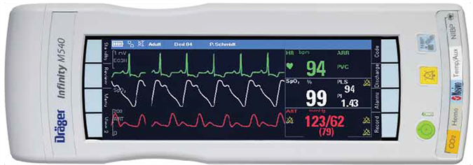
© Drägerwerk AG and Co. KGaA, Lubeck. All rights reserved.
Infinity M540 bedside monitor
RF requirements for Infinity Delta Series patient monitors
Table 3 lists the wireless specifications for Infinity Delta Series products working within the Cisco Catalyst wireless network.
Note: Specifications are version-specific and subject to change with new releases. Check with Dräger for the latest data at https://www.draeger.com/.
Table 3. Specifications for the Dräger Infinity Delta Series monitors
| Infinity Delta Series |
|
| Device specifications |
|
| Wireless layers 1 and 2 protocol |
IEEE802.11b/g |
| Wireless channels selection |
1 to 13 |
| Wireless security protocol |
WEP 128-bit, WPA2-Personal |
| Transmit power of device |
15 dBm |
| Receiver characteristics |
|
| Up to 54 Mbps |
-70 dBm |
| Infrastructure settings in coverage area |
|
| Maximum transmit power on access point |
15 dBm |
| Maximum number of Dräger devices supported per access point |
6 |
| Quality-of-service information |
|
| Average network traffic generated per device |
100kbps |
| Installation and design constraints |
|
| Maximum node capacity |
768 |
| IP address assignment |
Static |
| IP communication protocols used |
Multicast UDP, TCP, ICMP, |
| Dedicated SSID required |
1 (Delta and M540 share the same SSID) |
| Maximum SSID character length |
32, A to Z, upper and lower case supported, 0 to 9 |
| Routable |
Yes |
| VLAN |
Dräger multicast VLAN |
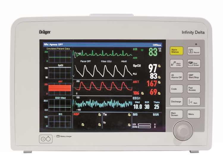
© Drägerwerk AG and Co. KGaA, Lubeck. All rights reserved.
Infinity Delta monitor
RF requirements for the Infinity M300 monitor
Table 4 lists the wireless specifications for Dräger Infinity M300 monitors working within the Cisco Catalyst wireless network.
Note: Specifications are version-specific and subject to change with new releases. Check with Dräger for the latest data at https://www.draeger.com/.
Table 4. Specifications for the Dräger Infinity M300 monitor
| Infinity network wireless specification |
Infinity M300 patient monitor (HW 0.3) |
Infinity M300/M300+ patient monitor (HW 0.4,0.5) |
| Device specifications |
||
| Wireless Layer 1 and 2 protocol |
IEEE802.11b/g |
802.11b/g/n (2.4 GHz); 802.11a/n (5 GHz) |
| Wireless channel selection |
1 to 13 |
802.11b/g/n: 1 to 13 802.11a/n: 36, 40, 44, 48, 149, 153, 157, 161 and 165 (UNII-1 and UNII-3, no DFS) |
| Wireless security protocol |
WPA2 – Personal mode |
WPA2 – Personal mode WPA2 – Enterprise mode; EAP-PEAP WPA2 – Enterprise mode; EAP-TLS |
| IEEE 802.11n rates supported |
N/A |
Up to 72.2 Mbps |
| Transmit power of device |
15 dBm |
15 dBm |
| Receiver characteristics |
||
| Up to 54 Mbps |
-65 dBm |
-65 dBm |
| Infrastructure settings in coverage area |
||
| Maximum transmit power on access point |
15 dBm |
15 dBm |
| Maximum number of Dräger telemetry devices supported per access point |
12 |
12 |
| Quality-of-service information |
||
| Average network traffic generated per device |
45kbits/sec |
45kbits/sec |
| Installation and design constraints |
||
| Maximum node capacity |
1024 |
1024 |
| IP address assignment |
Static |
Static |
| IP communication protocols used |
TCP |
TCP |
| Dedicated SSID required |
1 |
1 |
| Maximum SSID character length |
32, A to Z, upper and lower case supported, 0 to 9 |
32, A to Z, upper and lower case supported, 0 to 9 |
| VLAN |
Dräger non-multicast VLAN |
Dräger non-multicast VLAN |
For optimum performance, Infinity M300 monitors require a minimum signal strength of -65 dBm throughout the patient area or the relevant area as defined by clinical staff. This might exclude elevators or cafeterias in which the Infinity M300 will continue to process and display heart rate information but not be able to transmit that data back to the Infinity Central Station.
© Drägerwerk AG and Co. KGaA, Lubeck. All rights reserved.
Infinity M300 and M300+ Monitor
Infrastructure planning for Infinity Delta Series and M540 patient monitors
Scaling of patient-monitoring devices is important within the RF spectrum and equally important within the network. The number of monitors directly affects the number of multicast addresses required. Each patient monitor sends to a different multicast address, so this traffic can put a heavy demand on your network if your multicast capability does not match your requirements.
In a typical environment, patient monitors should be limited to six per access point, although the actual device maximums will vary with the capacity of your wireless network. Six monitors per access point generally provides more than enough capacity for patient data and other wireless applications. If your wireless design has no other applications beyond patient monitoring, you may be able to support more monitors per access point, although this configuration has not been tested. In addition, it may be prudent to provide for potential future wireless applications in the current design.
Again, patient-monitoring data is far more critical than typical voice data. Although an occasional packet drop can be tolerated, a strong radio frequency policy, security policy, and software change control, combined with a solid network design, are essential.
Architecture overview
Figure 7 illustrates a typical patient monitoring architecture that uses a standard core-distribution-access layer topology. Your monitoring solution can be locally connected or several Layer 3 hops away. However, if your solution requires the nurses’ station to be on a different broadcast domain from the wireless network, you should use a more robust Layer 3 multicast design. Whether this is a sparse-mode or dense-mode solution is up to the network architect.
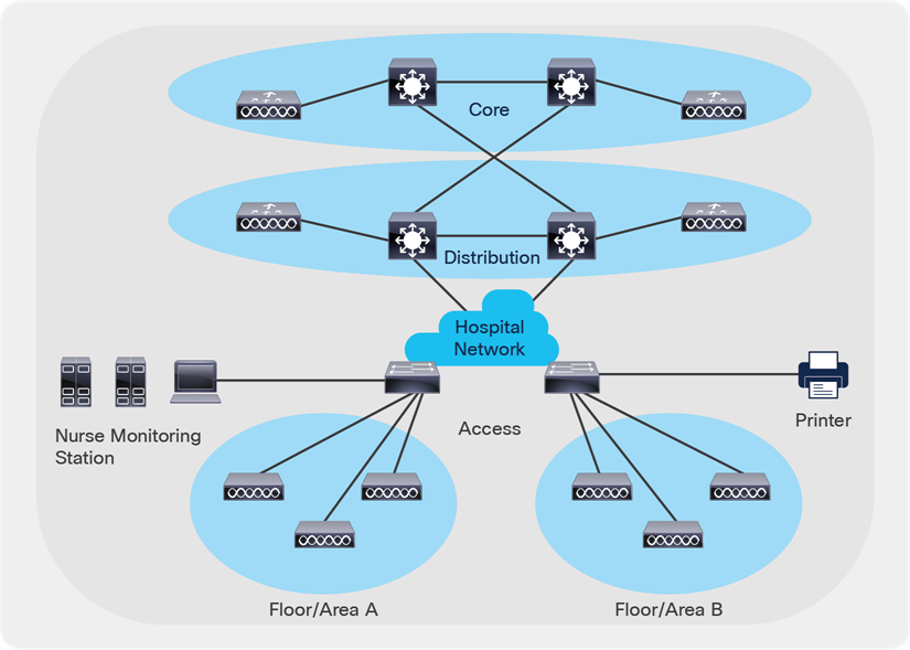
Typical patient monitoring architecture
Prerequisites
Working knowledge of IEEE 802.11 transmission and security standards, Cisco wireless LAN controllers, Cisco network switch equipment, and multilayer VLAN routing and trunking (VTP).
Topology
Figure 8 shows an example of a simple network topology with Cisco network devices and Dräger medical devices.
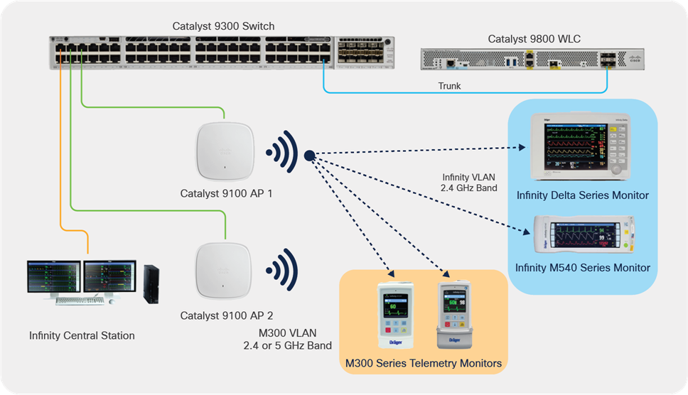
Example Cisco and Dräger network topology
Components
● Cisco Catalyst 9100 Access Points (9115AX, 9120AX Series)*
● Cisco Wave 2 access points (2800, 3700, 3800, 4800 Series)*
● Cisco Catalyst 9800 Series Wireless Controllers (9800-40, 9800-80, 9800-L, 9800- CL)
● Cisco network switch
● Dräger Infinity Central Station
● Dräger Infinity bedside monitors (Delta, M540)
● Dräger Infinity patient monitors (M300 Series)
Requirements
● Single, dedicated WLAN SSID for multicast-based patient monitors (M540 and Delta Series)
● Single, dedicated WLAN SSID for telemetry patient monitors (M300 Series)
● Wi-Fi Protected Access 2 - Advanced Encryption Standard / Pre-Shared Key (WPA2-AES/ PSK) (all) or WPA2-Enterprise for M300 telemetry devices
● The platinum-level Quality of Service (QoS) is recommended
◦ Note that the Differentiated Services Code Point (DSCP) value for Layer 3 QoS can be configured on the Infinity Central Station and M300 telemetry patient monitors. Default values are set to 48.
◦ If Delta Series patient monitors are in use, be sure to set the DSCP value on the Infinity Central Station to 0, as the Delta device does not support any other value.
● A Delivery Traffic Indication Message (DTIM) value of 1 is recommended
● Cisco IOS-XE 17.3.2 or later is recommended
Network switch requirements:
● Compliance with IEEE 802.3 standard
● Support for VLAN applications based on the 802.1Q standard
● All switches are managed; that is, they have a console to configure various features and VLANs
● An IGMP querier using IGMP v2 to prevent multicast traffic from being broadcast to all ports on the local VLAN. The IGMP query is considered a Layer 3 function, though some manufacturers have implemented this feature on Layer 2 switches
● Any Layer 2 switch must be capable of IGMP snooping
If M300 (wireless) devices are to be included, they should operate in a VLAN separate from the multicasting devices with routing capability to permit communication between the Infinity Central Station (ICS) and the M300s, or there should be two network cards on the ICS, one for the multicasting devices and one for the M300s.
IP routing
When using M300 and Infinity monitors, subnets need to be routed against each other. Routing to non-Dräger networks is neither required nor requested for keeping Dräger networks free of all (unwanted) network traffic and negative side effects to medical devices.
Maximum devices
There can be as many as 32 patient monitors in a monitoring unit, and up to 32 monitoring units in an entire Infinity network.
Network setup
The following information explains a typical network configuration used for this documentation. Your particular configuration may vary depending on other wireless and wired dependencies. In these examples, the access point is registered to the wireless controller (WLC). The WLC is connected to the Layer 2 switch. The switch that connects the WLC and access point is also connected to the Dräger monitoring network. The following is the configuration for two WLANs, one for the Dräger Infinity bedside monitors and the other for the M300 patient devices. This setup will be done on the Catalyst 9800 Series Wireless Controller.
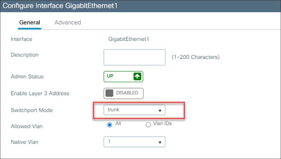
Creating a trunk interface for the network
GUI:
1. Navigate to Configuration -> Interface -> Ethernet
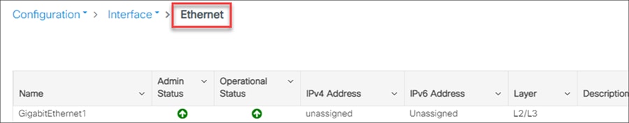
2. Select the interface that will connect to your networks, and be sure to create a trunk interface that will allow you to deploy multiple networks in different VLANs.
Command-Line Interface (CLI):
WLC(config)# interface GigabitEthernet1
WLC(config-if)# switchport mode trunk
Creating and enabling VLANs and SVIs for the Infinity devices and the M300 devices
GUI:
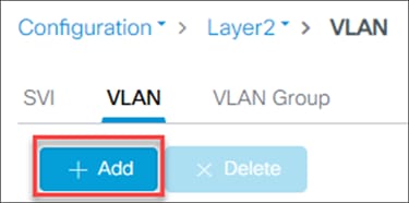
1. Navigate to Configuration -> Layer 2 -> VLAN -> VLAN
2. Add a VLAN for the Infinity devices.
3. Create the VLAN using the VLAN ID and ensure that IGMP Snooping and ARP Broadcast are enabled.
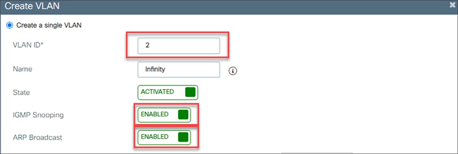
4. Repeat steps 2 and 3 for the M300 VLAN. IGMP snooping is not required for the M300 VLAN.
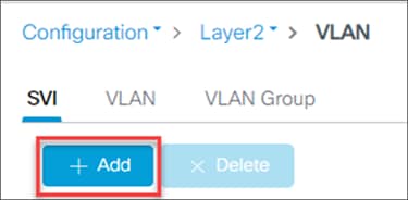
5. Go to Configuration -> Layer 2 -> VLAN -> SVI
6. Add a Switch Virtual Interface (SVI) for the Infinity devices.
7. Create the SVI using the same VLAN ID as the VLAN number.
8. Assign the SVI an IPV4 address using a static IP address.
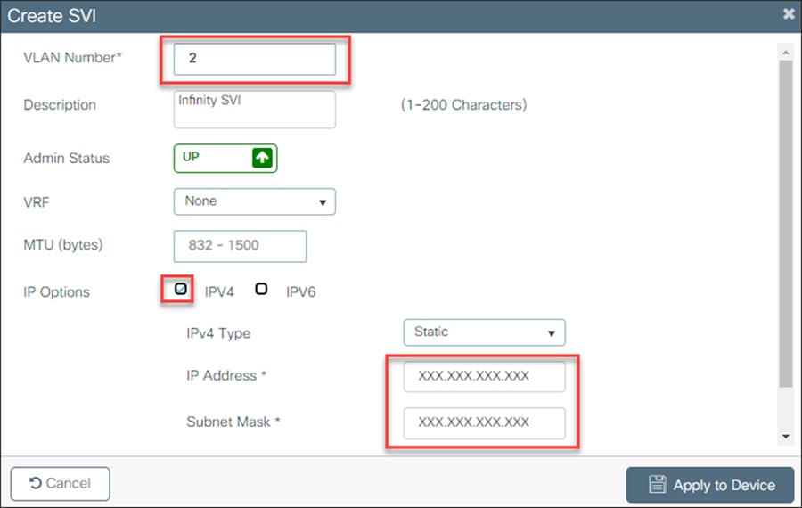
9. Repeat steps 6 through 9 for the M300 SVI.
Command-Line Interface (CLI):
WLC(config)# Vlan X1, X2
WLC(config)# Vlan configuration X1, X2
WLC(config-if)# arp broadcast
WLC(config)# interface Vlan X1
WLC(config-if)# ip address X.X.X.X X.X.X.X
WLC(config)# interface Vlan X2
WLC(config-if)# ip address X.X.X.X X.X.X.X
Creating the WLANs
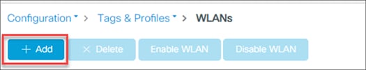
1. Navigate to Configuration -> Tags and Profiles -> WLANs
2. Add a WLAN.
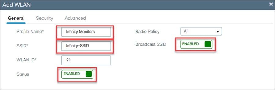
3. Create and name a WLAN for the Infinity beside monitor devices.
4. Enable the WLAN and broadcast the SSID.
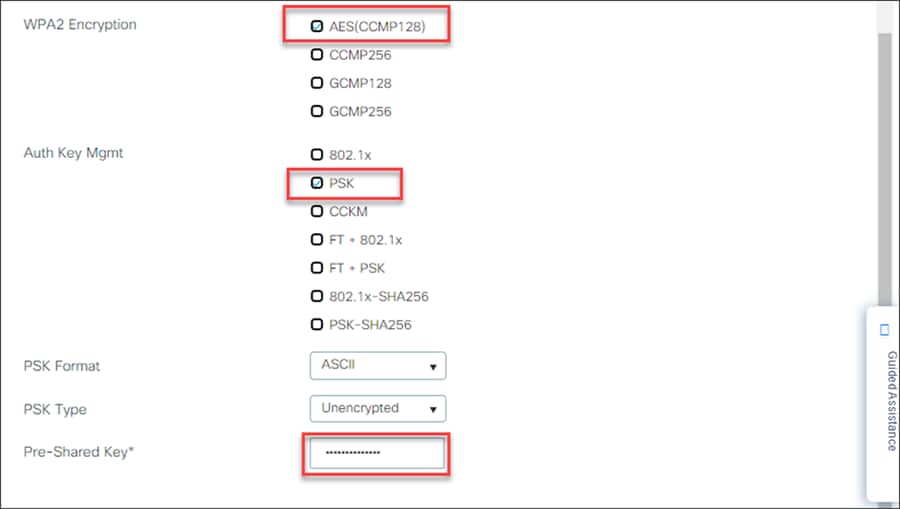
5. Secure the WLAN traffic using WPA + WPA2.
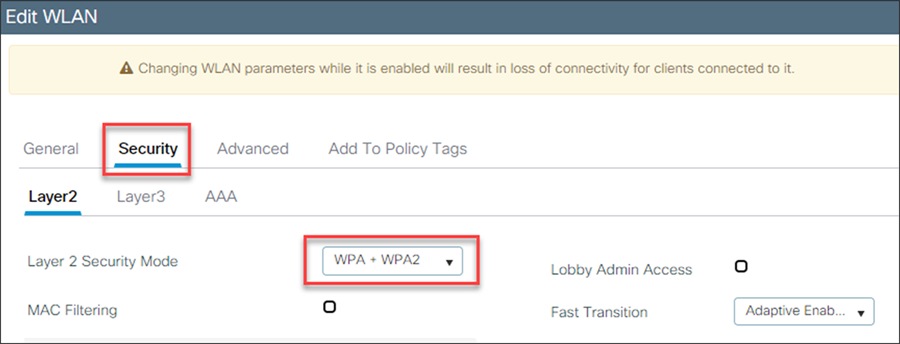
6. Encrypt the WLAN traffic using AES (disable Temporal Key Integrity Protocol [TKIP]), and control access to the WLAN with an ASCII PSK.
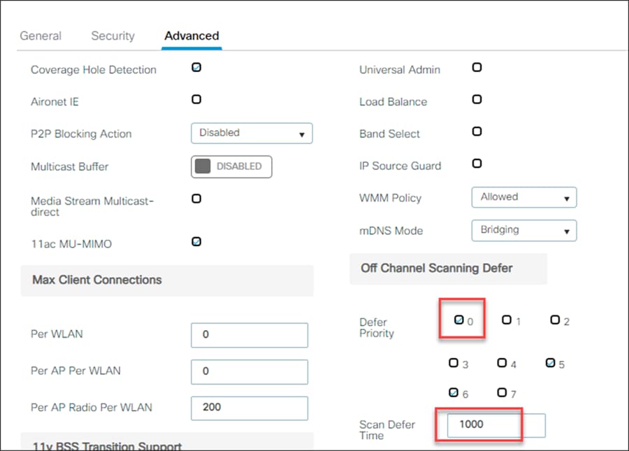
7. On the Advanced tab, within the Off Channel Scanning Defer section, set the Defer Priority to 0 and the Scan Defer Time to 1000 ms.
8. In a multiple controller environment, the VLAN and SSID must match to ensure seamless roaming.
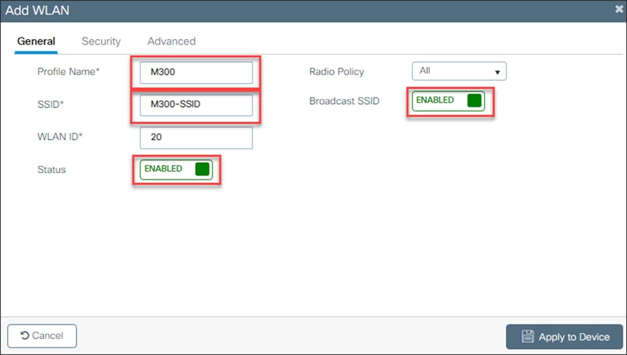
9. Create and name a WLAN for the M300 telemetry devices.
10. Enable the WLAN and broadcast the SSID.
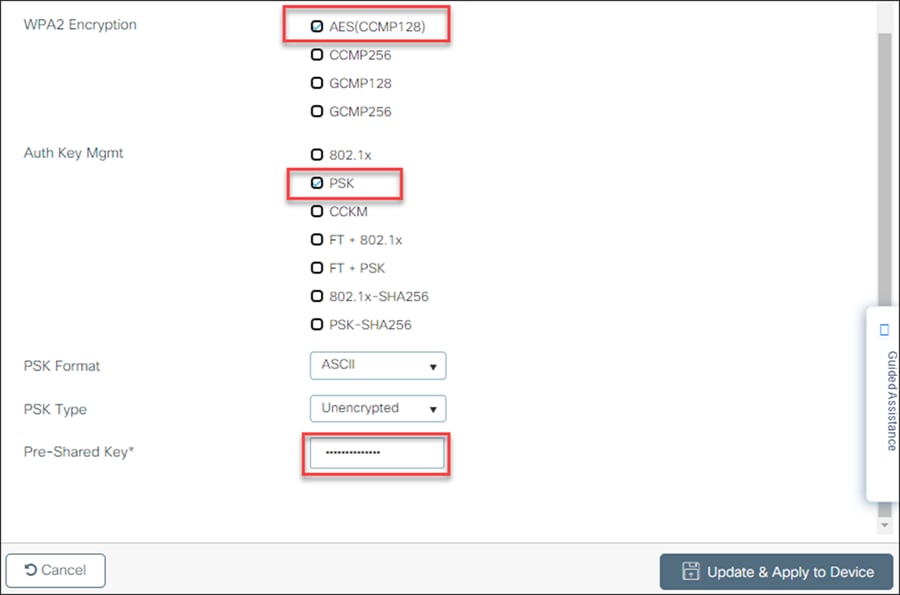
11. Secure the WLAN traffic using WPA + WPA2.
The M300 also supports WPA2 Enterprise. If you are interested, please reach out to a Dräger representative.

12. Encrypt the WLAN traffic using AES (disable Temporal Key Integrity Protocol [TKIP]), and control access to the WLAN with an ASCII PSK.
13. In a multiple-controller environment, the VLAN and SSID must match to ensure seamless roaming.
Command-Line Interface (CLI):
WLC(config)# wlan infinitywifi 1 infinitywifi
WLC(config-if)# security wpa psk set-key ascii 0 password1
WLC(config-if)# no security wpa akm dot1x
WLC(config-if)# security wpa akm psk
WLC(config-if)# channel-scan defer-priority 0
WLC(config-if)# channel-scan defer-time 1000
WLC(config-if)# no shutdown
WLC(config)# wlan m300wifi 2 m300wifi
WLC(config-if)# security wpa psk set-key ascii 0 password2
WLC(config-if)# no security wpa akm dot1x
WLC(config-if)# security wpa akm psk
WLC(config-if)# no shutdown
Policy tags
Create a policy profile, add the VLAN ID, and set the QoS policy
GUI:
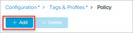
1. Navigate to Configuration -> Tags and Profiles -> Policy.
2. Add a policy.
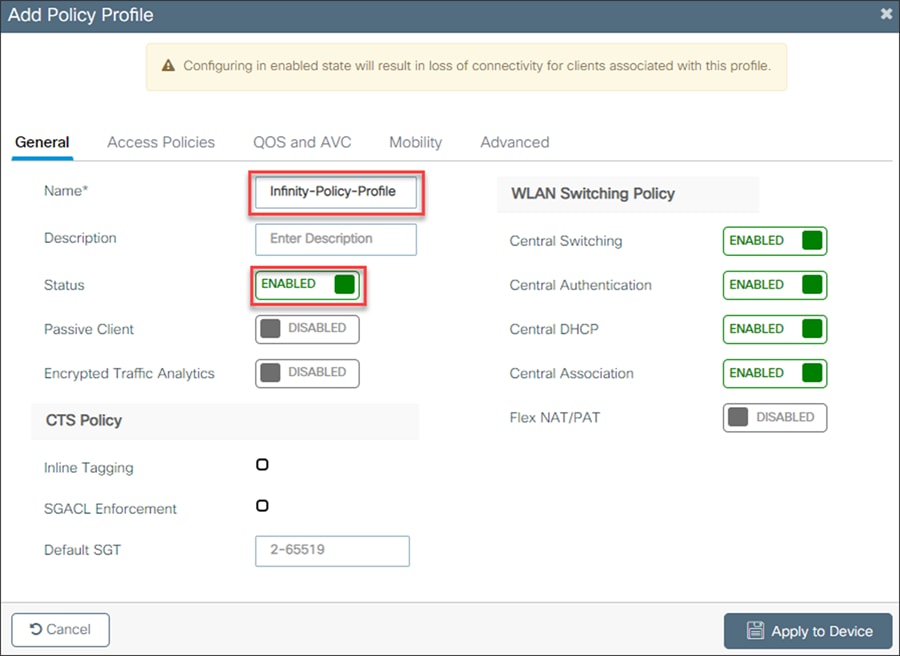
3. Give the policy a name and enable the policy profile for Infinity devices.
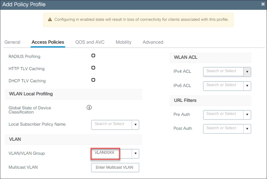
4. In the Access Policies section, change the VLAN/VLAN group to the VLAN for the Infinity devices.
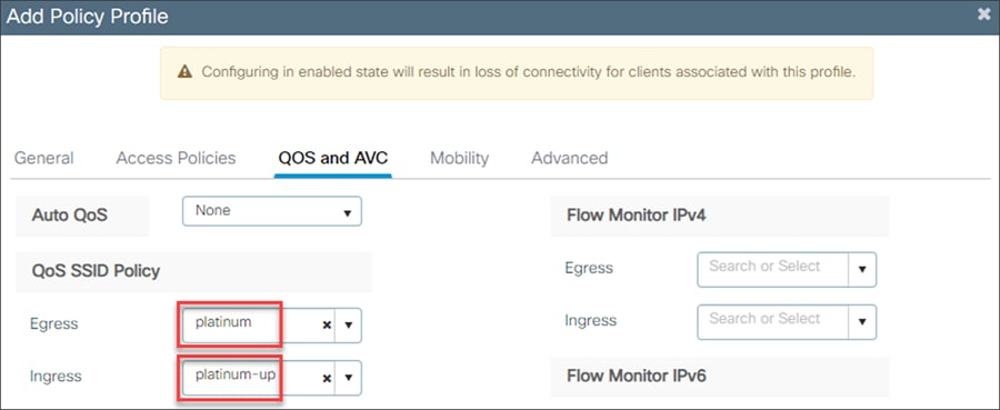
5. In the QoS and AVS section, enable platinum QoS for egress traffic and platinum-up QoS for ingress traffic.
6. Repeat steps 2 through 5 for the M300 WLAN policy profile.
Command-Line Interface (CLI):
WLC(config)# wireless profile policy Infinity-Policy-Profile
WLC(config-if)# description Infinity-Policy-Profile
WLC(config-if)# session-timeout 86400
WLC(config-if)# vlan X1
WLC(config-if)# service-policy input platinum-up
WLC(config-if)# service-policy output platinum
WLC(config-if)# no shutdown
WLC(config)# wireless profile policy M300-Policy Profile
WLC(config-if)# description M300-Policy Profile
WLC(config-if)# session-timeout 86400
WLC(config-if)# vlan X2
WLC(config-if)# service-policy input platinum-up
WLC(config-if)# service-policy output platinum
WLC(config-if)# no shutdown
Map the WLAN to the policy profile
GUI:
1. Navigate to Configuration -> Tags and Profiles -> Tags.
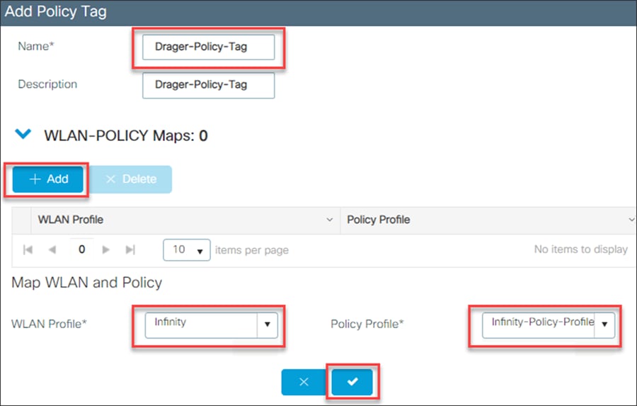
2. Add a new policy tag.
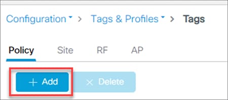
3. Name the policy tag and add a new WLAN policy map.
4. Map the Infinity WLAN and the Infinity policy profile together.
5. Repeat steps 2 through 4 to map the M300 WLAN to the M300 policy profile.
Command-Line Interface (CLI):
WLC(config)# wireless tag policy Drager-Policy-Tag
WLC(config-policy-tag)# Infinity policy Infinity-Policy-Profile
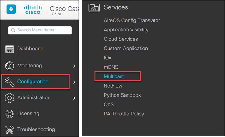
Multicast settings
Configure multicast settings for the Infinity WLAN
GUI:
1. Go to Configuration -> Services -> Multicast.
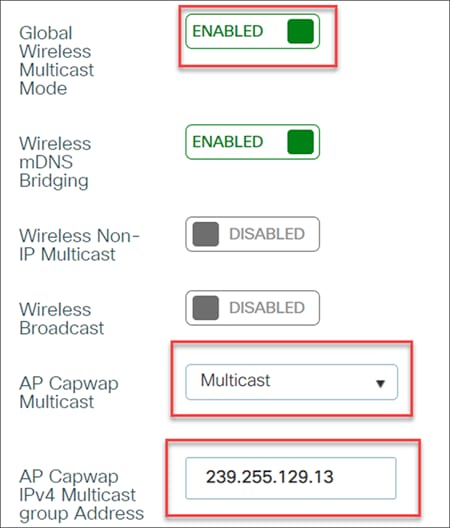
2. Enable Global Wireless Multicast Mode.
3. Set AP Capwap Multicast to Multicast and give the AP Capwap IPv4 Multicast Group Address the value of your multicast address. This multicast address is used by the wireless infrastructure, so it should be different from the multicast groups used within the Infinity monitoring solution as described in, for example, Table 1.
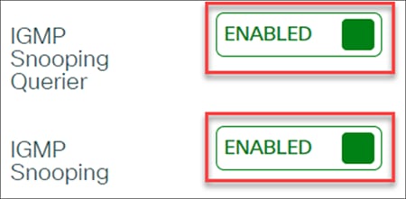
4. Ensure that IGMP Snooping Querier and IGMP Snooping are enabled.
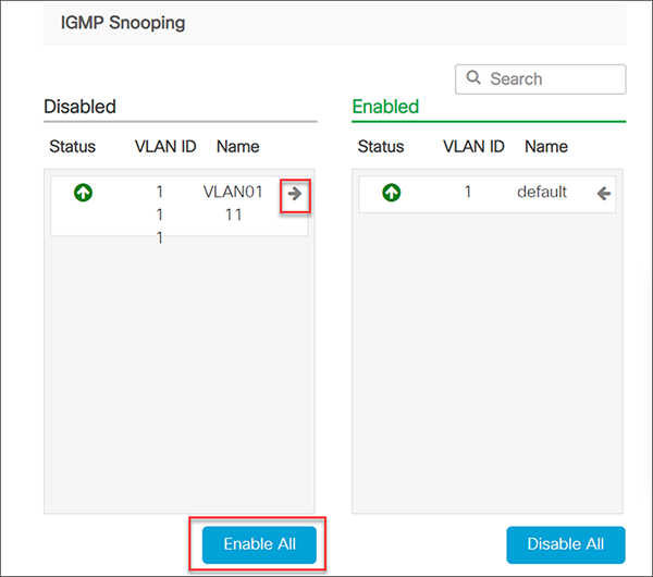
5. Enable IGMP Snooping for the VLANs used in the WLAN by pressing the arrow icon on each VLAN or enabling all disabled VLANs.
Command-Line Interface (CLI):
WLC(config)# wireless multicast
WLC(config)# wireless multicast X.X.X.X
WLC(config)# ip igmp snooping
WLC(config)# ip igmp snooping Vlan X
WLC(config)# ip igmp snooping querier
Verification:
WLC# show ip igmp snooping wireless mgid
WLC# show wireless multicast group summary
Multicast traffic
Multicast is required to connect to certain Dräger devices. Multicast, like broadcast, permits a single transmission to reach multiple receivers in a network. A broadcast reaches all devices in the local VLAN and is inefficient for devices that do not need the data, since they have to evaluate and discard the information. The broadcast is “flooded” to all ports in the VLAN. In contrast, a multicast is delivered only to ports from which a request for the data has been issued.
When IGMP is enabled, at fixed intervals the designated switch issues, as an IGMP query, the question “Who needs what multicast addresses?” This function is typically reserved for a Layer 3 switch, or router, and that “IGMP queried” is responsible for maintaining a table of all multicast addresses needed in the VLAN. It transmits the query to its ports in the VLAN, and so to all connected devices, including switches, workstations, etc.
When a connected device such as a patient monitor receives the IGMP query, it responds with one or more messages per needed address. As the Layer 2 switch receives the responses, termed “IGMP group membership reports,” it builds or updates a table that matches multicast addresses with port numbers. It also passes the membership reports up to the IGMP queries. The term for this behavior is “IGMP snooping.” The IGMP queries add the information to their own larger table of the same type. Group membership refers to the group of parties that need to receive data sent to a certain multicast address. A device can transmit multicast traffic without being a member of that multicast group. The data flow is governed by the receivers, the group members.
Multicast is often used for training or seminars, in which a single transmitter sends data to a number of receivers. However, the Infinity devices use multicast in a different way. Each patient monitor transmits and receives packets sent to certain multicast addresses. This allows local Infinity patient monitors to display the list of other Infinity patient monitors in the group and report alarm conditions from other bedsides on the local screen. In addition, the mechanism permits an Infinity patient monitor to display waveform data from a remote Infinity patient monitor in a lower subwindow of its display.
Coverage limits
The following limits must not be violated:
● Minimum signal strength, measured at client (received signal strength indication [RSSI]): -65 dB
● Minimum signal-to-noise ratio (SNR), measured at client: 25 dB
● Maximum transmit power at access point (including antenna gain): 15 dBm
● Maximum 10 access points on the same channel visible at the same time for the client (80 dB threshold)
● No other (non-Wi-Fi or rogue AP) radio sources within the IEEE 802.11a/b/g/n frequency band