Enterprise Best Practices for iOS, iPadOS, and MacOS Devices on Cisco Wireless LAN White Paper
Available Languages
Bias-Free Language
The documentation set for this product strives to use bias-free language. For the purposes of this documentation set, bias-free is defined as language that does not imply discrimination based on age, disability, gender, racial identity, ethnic identity, sexual orientation, socioeconomic status, and intersectionality. Exceptions may be present in the documentation due to language that is hardcoded in the user interfaces of the product software, language used based on RFP documentation, or language that is used by a referenced third-party product. Learn more about how Cisco is using Inclusive Language.
This document is intended for IT professionals responsible for designing, deploying, and managing Cisco® Wireless LANs (WLAN). This reference design guide is updated to account for Cisco and Apple’s joint recommendations focused on both Local and Cisco FlexConnect® mode configurations for a controller-based Cisco WLAN. It assumes the reader has a working knowledge of Cisco WLAN components and features, basic IP networking, and voice over IP (VoIP). The best practices cover design considerations, recommended network setup, and configuration guidelines to provide the best possible services for iOS, iPadOS, or macOS devices on a Cisco wireless LAN while maintaining infrastructure security.
This document highlights general best practices and controller configurations for different use cases and specific guidance for iOS, iPadOS, and macOS devices.
As per established enterprise best practices and Cisco and Apple's joint recommendation, the use of the 2.4-GHz band is not considered to best suit the needs for business and/or mission-critical enterprise applications. Cisco and Apple strongly recommend a 5-GHz-only (802.11a/n/ac/ax) wireless network for iOS, iPadOS, and macOS devices. This document focuses entirely on a 5-GHz network layout as a best practice.
Today's bring-your-own-device era has positively encouraged end users to carry personal devices that can connect to a Wi-Fi network, with most workplaces now seeing a minimum of two to three wireless-capable devices per user. It has become necessary for IT administrators to design and develop the Wi-Fi infrastructure to rightly balance and accommodate an open-access network environment without reducing the security of network resources.
In addition to security concerns, these environments present several challenges regarding quality of service, 2.4-GHz vs. 5-GHz radio coverage, client roaming across an Access Point (AP) scenario, and the presence of legacy client devices on the wireless network. With more business-critical applications being used by employees on personal devices, there is a high demand for pervasive wireless connectivity in parallel with responsive application performance.
Apple devices constitute a significant presence in today's enterprise environments. To ensure the best possible service, several different factors must be considered, including Radio Frequency (RF) conditions, client connectivity, network visibility, Quality of Service (QoS), and network monitoring. Coexistence with larger mobile devices, such as the MacBook, also must be ensured. These laptops also require optimized service. This document includes important guidelines for configuring the Cisco Wireless LAN Controller (WLC) with respect to these factors.
Deploying real-time applications, such as voice over WLAN (VoWLAN), on a shared medium like Wi-Fi in a production environment requires careful planning, consideration, and design. Many administrators are asked to add VoWLAN onto an existing wireless infrastructure originally designed to meet very different needs. Others have the benefit of starting from scratch and taking VoWLAN into consideration in the original design. Either path raises an important question for the administrator: How can I ensure the best possible end-user experience for my Cisco wireless environment?
Apple continually adds support for industry-standard technologies that enhance the connectivity of Wi-Fi clients; however, some of these enhancements are supported only on specific iOS devices and Mac computers and operating system releases. Some other enhancements are solely targeted at iOS devices, which are expected to be more mobile and more susceptible to sudden RF changes than Macs running macOS. It is important to learn which iOS devices (and iOS releases) will likely be used on your wireless network so that you can tune your network to its maximum potential. To assist in this process, Apple maintains a series of knowledge base articles that list which devices support the various technologies, as described in the Apple Roaming on iOS document.
RF design guidelines for iOS, iPadOS, and macOS devices on a Cisco WLAN
The first step in WLAN deployment is to perform a site survey to assess the RF behavior in a specific environment. Many issues can arise in a wireless network due to poor planning, resulting in poor coverage. When analyzing existing wireless deployments, personnel often discover that site surveys were not performed properly, or that the site survey has been omitted altogether.
One key factor for continued success is to make sure that the site survey considers the current and future needs of the wireless devices and applications in use. This must include use cases and account for the various device types you plan on using and deploying on the wireless network in the foreseeable future. Different use cases have different site survey methodologies. For instance, a general use (data or voice) only site survey can vary significantly from a mission-critical network that requires voice, video, data, and location-based services.
Different devices, such as laptops and smartphones, have different wireless characteristics that must be considered during the design and site survey of the wireless network. In most cases, designing the network for expected client devices that are most sensitive to changes in RF conditions is a sound principle. Smartphones, because of their small form factor and because they are moved in multiple directions and held close to the human body (a source of RF absorption), are usually more susceptible to sudden RF changes than larger computers. It also helps to understand the transmit power characteristics of the wireless client devices to ensure that access points and associated devices transmit at a similar RF power level.
The recommendation for network administrators is to conduct a site survey with the most common wireless client you expect to be used in the network. For example, if you expect that most wireless clients in your network will have a 1x1 or 2x2 radio, there is no need to conduct a site survey with a 3x3 wireless client. We recommend using the weakest client from an RF perspective to conduct this site survey to ensure that wireless clients at different levels get great coverage.
RF design recommendations for iOS, iPadOS, and macOS devices on a Cisco WLAN
● Use an 802.11a/n/ac/ax 5-GHz-based design for all Apple devices.
● Optimal cell edge recommendation for iOS devices is -67 dBm or better (-65 dBm is better for typical high-density enterprise deployments). Mac computers can accept a cell edge at -72 dBm. An optimal WLAN deployment will require, at the cell edge, a minimum of two APs in 5 GHz at -67 dBm as measured by the Apple client.
● Average channel utilization should be less than 40%.
● Maintain a minimum signal-to-noise ratio (SNR) of 25 dB.
● 802.11 retransmissions should be kept under 15%.
● Packet loss should remain under 1%, and jitter should be kept to less than 100 ms.
Wireless metrics such as channel utilization, SNR, retransmissions, etc., can be measured through Cisco’s Wireless Config Analyzer Express (WCAE) tool. For more details, visit WCAE’s DevNet Page.
These are general recommendations and may not fully address any potential transmit power changes in some situations, such as full and low battery levels, along with possible attenuation when the device is being covered with the hands while in active use or is passively stored (such as in the pocket) when not in direct use.
Table 1. Basic steps to a successful RF design
| Step |
Description |
Purpose |
| 1 |
Definition |
Define what applications and clients will be deployed and who the stakeholders are. |
| 2 |
Coverage areas and project phases |
Define what areas within the site will support only general applications and voice plus general applications on the wireless network. |
| 3 |
Plan approval |
Gain buy-in from all key stakeholders. |
| 4 |
RF audit and site survey |
Validate and adjust the design. |
| 5 |
Deploy infrastructure |
Implement the design. |
| 6 |
RF test |
Test implementation on deployed infrastructure. |
| 7 |
Final adjustments |
Adjust access point settings. |
| 8 |
Ongoing operation support |
Transition to sustaining support with adaptation to usage changes. |
Cisco and Apple recommend a 5-GHz-only coverage design when designing for Apple devices on a Cisco wireless network. For environments where 2.4-GHz-only devices are present, a separate wireless network could be added to allow the 2.4-GHz devices to connect to the network.
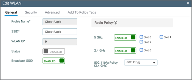
Configuring radio policy to 5 GHz on a Cisco Catalyst® WLC
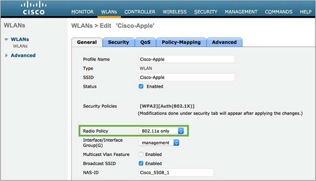
Configuring radio policy to 5 GHz on an AireOS WLC
The 5-GHz channels are free of common devices operating on the 2.4-GHz frequency, such as Bluetooth, video cameras, and microwave ovens. With more channels being available on 5 GHz, there is higher frequency reuse, along with the channel utilization being generally lower due to the reduced co-channel interference and lower channel overlap ratio as compared to 2.4 GHz.
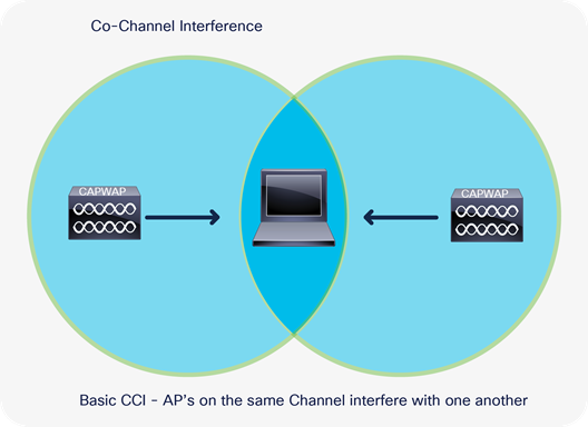
Access points on the same channel cause co-channel interference
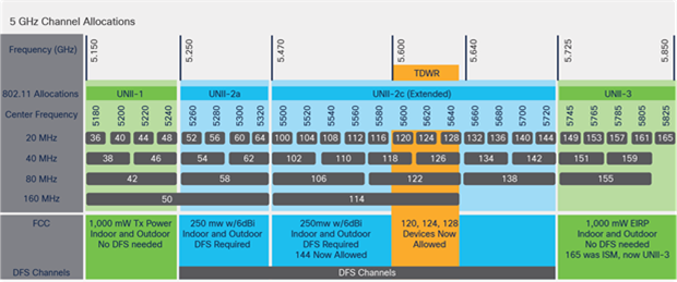
For reasons of channel capacity, and in co-channel interference situations, you may need to use Dynamic Frequency Selection (DFS) channels. DFS is the process of detecting radar signals used by departments such as the military and weather services, which must be protected against interference from 5-GHz radios running over Wi-Fi networks. Upon detection, the AP must switch the operating channel of the 5-GHz radio to a channel that is not interfering with the radar systems.
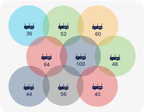
Channel distribution example in a 5-GHz network design
Cisco and Apple recommend carefully monitoring the DFS channels for radar activity via the controller traps to plan and avoid having frequent DFS events that cause periodic channel changes across APs.
Considering optimal application performance, a wireless network typically reaches its maximum capacity when channel utilization is between 70% and 80% on average. To calculate the interference on your AP’s operating channel, subtract the channel utilization from the AP’s transmit and receive values. The channel utilization, transmit utilization, and receive utilization can be found on the Catalyst controller UI at Monitoring > Wireless > AP Statistics > [select an AP] > 360 View.
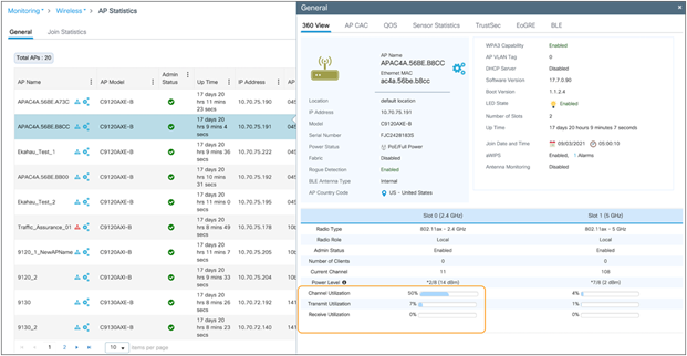
Channel, transmit, and receive utilization data on a Catalyst controller
This value, especially for latency-sensitive and real-time applications such as VoWLAN, should not be over 30%; otherwise it may affect users’ wireless experience. To mitigate such issues, as a best practice, it’s critical to ensure that proper QoS configurations such as Fastlane, Fastlane+, Application Visibility and Control (AVC), etc. are enabled.
High channel utilization values may be an indication of new sources of interference, AP outages, or an influx of new Wi-Fi devices. Cisco recommends that customers create a baseline measurement of their existing client count, the number of clients per AP, configured channel numbers, and current channel utilization prior to deploying additional devices.
Cisco's Radio Resource Management (RRM) is enabled on the controller by default and was designed to manage the RF environment in a dynamic way with little to no user intervention. RRM calculates and assigns the best channels and power combinations using measured over-the-air metrics. It keeps track of high utilization on all channels and will mitigate co-channel assignments and balance power. If no open channels are available, or if the APs are simply too close together, the only choice remaining is to share the channel with an existing user. This happens in congested environments, and two different networks may have to share the same bandwidth.
Cisco recommends carefully monitoring the 5-GHz Wi-Fi channels that are affected by continuous high channel utilization conditions and add these channels to the Dynamic Channel Allocation (DCA) exclusion list if the interference is recurring or cannot be mitigated. Excluding a channel from the DCA list should be done only as a last resort. Cisco recommends channel exclusion with the use of RF profiles to effectively apply the removal of the channel(s) to only the affected APs, and not globally across all APs.
Note: Refer to the RRM guidelines in the Enterprise Mobility Design Guide for more details: https://www.cisco.com/c/en/us/td/docs/wireless/controller/8-5/Enterprise-Mobility-8-5-Design-Guide/Enterprise_Mobility_8- 5_Deployment_Guide.html.
To estimate whether the current 5-GHz AP coverage is sufficient for applications running on Apple devices, the Cisco WLC provides a friendly link test tool to determine the AP’s view of the client signal. In addition, Apple provides a wireless network scanner for iOS and iPadOS in its AirPort Utility app. An SNR or 25 or higher should always be maintained. The same link test can be run for a Mac computer.
In 802.11a, a 5-GHz channel uses a channel width of 20 MHz. With the adoption of 802.11n, 802.11ac, and 802.11ax, channel bonding capability was added to allow multiple 20-MHz channels to bond together and form a single channel with a greater width. Doubling the channel bandwidth from 20 to 40 MHz enables a single transmission to carry approximately twice as much data at the same time, effectively doubling the throughput of the wireless network. With 802.11ac and 802.11ax, 5 GHz offers you a choice of 20-MHz, 40-MHz, and 80-MHz (160 MHz with 802.11ac and 802.11ax) channel width modes.
Channel bonding example for 20-MHz, 40-MHz, and 80-MHz channel widths on a 5-GHz network
Cisco and Apple recommend the use of 40-MHz channel widths in environments where throughput performance is required, and 20 MHz for environments with a high density of APs and clients. To allow for an efficient 40-MHz-wide deployment, the use of DFS channels may become necessary to achieve optimal frequency reuse and reduce the likelihood of co-channel interference. Without DFS channels enabled in an FCC-regulated domain, four 40-MHz channels are available. With DFS channels enabled, the number of 40-MHz channels available increases to 12 (in the United States).
Although using 80-MHz-wide channel bonding may at first seem to boost an individual client’s performance, in an environment with a high density of APs, the co-channel interference due to limited spectrum availability can potentially reduce the overall network performance.
Therefore, until 6 GHz is commonly available and tested, the use of an 80-MHz channel width design is not recommended. (This document will be revised to include 6 GHz once it is commonly available.) If necessary, it should be considered only for low-AP-density deployments where co-channel interference can be easily avoided.
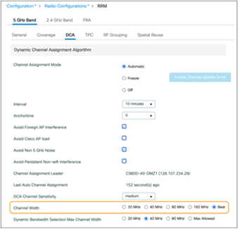
Configuring channel width from the Catalyst controller user interface
For Catalyst, navigate to Configuration > Radio Configurations > RRM > DCA and specify the width of the channel to be used.
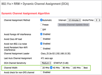
Configuring channel width from the AireOS controller user interface
For AireOS, navigate to Wireless > 802.11a/n/ac > RRM > DCA and specify the width of the channel to be used.
Choose 20, 40, 80, or 160 MHz. RRM can also automatically determine the best width based on your network environment.
DCA bandwidth can also be selected using an RF profile and applied only to APs contained in a specific AP group if a global assignment is not desired.
You can use the data rate settings to choose which data rates the wireless devices can use for data transmission. There is a direct correlation between data rates, performance, range, and reliability. When working with Apple devices, the strategy needs to be comprehensive and include all possible devices that will connect to the network and should consider the AP density of the deployment. There are two possible paths:
● Maximizing range: If the requirement is to increase the range, consider enabling low data rates. Lower data rates require lower signal levels and SNR at the receiver to decode the signal. This allows client devices to maintain a reliable connection to an AP from a greater distance. The maximum range approach may impact application performance for the client devices, especially for time-sensitive voice and video types of applications. Lower data rates typically require more airtime, and overall cell capacity (and hence user experience) can potentially be reduced.
● Maximizing performance: If the objective is to deploy a high-performance WLAN, improve roaming, and help mitigate the effects of co-channel interference by reducing the cell coverage, consider configuring higher data rates and disabling low data rates. Avoid being too aggressive on the minimum data rates, as this could prevent a client device from establishing a reliable connection, resulting in decreased performance.
The IEEE 802.11a standard provides data rates of 6, 9, 12, 18, 24, 36, 48, and 54 Mbps, with 54 Mbps being the maximum data rate.
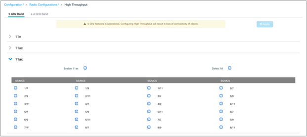
Configuring the data rates for the 5-GHz network on a Catalyst controller
For the Catalyst controller, navigate to Configuration > Radio Configuration > High Throughput to specify the rates at which data can be transmitted between the A P and the client.
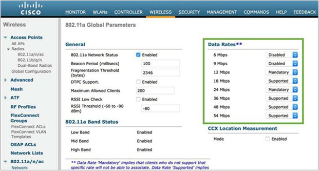
Configuring the data rates for the 5-GHz network on an AireOS controller
For an AireOS controller, navigate to Wireless > 802.11a/n/ac > Network to specify the rates at which data can be transmitted between the AP and the client.
You can set each data rate to one of three modes:
● Mandatory: Allows transmission at this rate for all packets, both unicast and multicast. At least one data rate needs to be set to mandatory on the APs, and all clients that associate with the AP must be able to physically support this data rate on their radio to be able to use the network. Additionally, for the wireless clients to associate with the AP, they should be able to receive packets currently set at the lowest mandatory rate, and their radios must physically support the highest mandatory data rate. If they do not receive the currently lowest mandatory rate frames, the client may miss beacons, which may lead to disconnection. If more than one data rate is set to mandatory, multicast is sent at the highest common mandatory rate of all associated clients. Broadcasts are always sent at the lowest (not highest) mandatory rate.
● Supported: Allows transmission at this rate for unicast packets only. The wireless clients always attempt to transmit and receive at the highest possible data rate. Note that allowing a supported data rate below the minimum mandatory data rate may inhibit roaming, as it increases the overlap area of the cells if not properly evaluated.
● Disabled: The AP does not transmit data at this rate.
Configuring low data rates as mandatory increases the range at which packets sent by the AP can be received. The lower you set the lowest configured mandatory data rate, the greater the range of beacons and other packets from the AP. This increases the cell size of the access points, and in a site with few APs this may be desirable, but if the density of mobile clients is high, this will likely rob the site of bandwidth and lead to poor application performance.
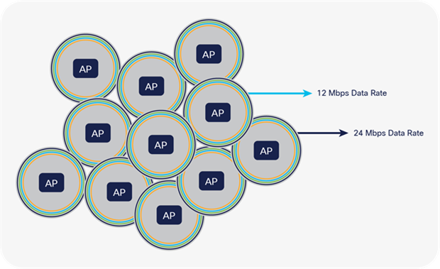
Example to show how data rates impact the cell size for the APs
Cisco and Apple recommend a minimum data rate of 12 Mbps and enabling 12 Mbps and 24 Mbps as the two mandatory data rates as a general best practice for Apple devices on a Cisco WLAN. If the 5-GHz coverage is marginal, setting 6 Mbps as the lowest mandatory rate could potentially resolve issues.
802.11n, 802.11ac, and 802.11ax rates all are of the supported type (the 802.11 standard does not include them in the mandatory category). Disabling 802.11n/ac rates was not found to improve the marginal performance of wireless clients. As such, Apple and Cisco do not recommend disabling low 802.11n/ac rates, even when low 802.11a rates are disabled.
It is advisable to check on the administration logs, traps, and alerts using the controller dashboard and Cisco DNA Center to monitor and verify that client devices are connecting to the network at the configured data rates. Indications that data rates are not set properly may include:
● Coverage hole alarms
● High levels of channel utilization
● Excessive retransmissions
● Clients not able to connect or encountering roaming issues
When iOS or iPadOS devices connect to a WLAN with enterprise security using 802.1X/Extensible Authentication Protocol (EAP), it is recommended that you take either of the following into consideration for the deployment:
1. Manage iOS or iPadOS client devices through a Mobile Device Management (MDM) solution and push the certificate chain used for the WLAN in question in a corresponding profile. For more information on this, refer to the following documentation from Apple: https://support.apple.com/en-us/HT207866
2. Alternatively, if option 1 above is not possible, use a wildcard certificate in the certificate chain used for 802.1X/EAP authentication on the RADIUS/Authentication, Authorization, and Accounting (AAA) server(s) that will service the WLAN in question. For more information on wildcard certificates with Cisco Identity Services Engine (ISE), you can refer to the following document and corresponding excerpt accordingly: https://www.cisco.com/c/en/us/td/docs/security/ise/3-1/admin_guide/b_ise_admin_3_1.html
Wildcard certificates address issues seen with iOS or iPadOS devices in which the client stores trusted certificates within the profile and does not follow the iOS keychain where the signing root is trusted. When an iOS or iPadOS client first communicates with a secure network, it does not explicitly trust the network certificate, even though a trusted Certificate Authority (CA) has signed the certificate. With a wildcard certificate, the certificate will be the same across all secure networks under the same authority, so the user must accept the certificate only once, and successive authentications to different networks proceed without error or prompting.
If neither of the above methods is used, it is expected that the iOS or iPadOS client device will prompt the user to trust the certificate every time a new RADIUS/AAA server is used to authenticate the iOS or iPadOS client device to the same WLAN. For instance, if the same WLAN is used in two different campuses, each of which has a dedicated RADIUS/AAA server, the end user will have to once again trust the certificate that was used during the 802.1X/EAP authentication, even if either the intermediate or root certificate is signed by the same CA and was previously trusted at the prior location using that same WLAN. The same may occur if the authentications to the same WLAN are load-balanced among several RADIUS/AAA servers, a failover event occurs between RADIUS/AAA servers, and so forth.
Optimizing quality of service with Fastlane
To optimize application traffic, Cisco and Apple have created a joint solution known as Fastlane that improves QoS experience. It allows users to decide the traffic types that should be prioritized, which enhances the user’s experience for certain applications.
Note: Fastlane+ is a separate feature from the existing Fastlane solution. While the name is similar, they provide separate, nonoverlapping benefits.
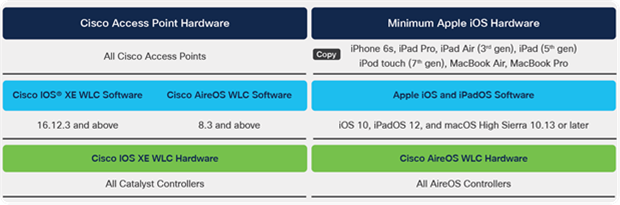
Software and hardware compatibility matrix
Refer to the following table for the Fastlane software and hardware interoperability.
Table 2. Fastlane compatibility matrix
Configuring a WLAN controller for QoS can be time-consuming. This configuration also implies the configuration of multiple combined elements, which may be a challenging task for administrators.
To facilitate optimal configuration of QoS on a WLAN controller, Cisco has created a Fastlane option in the QoS tab of the WLAN configuration pages.
Configuring Fastlane on the WLAN for a Catalyst controller
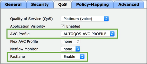
Configuring Fastlane on the WLAN for an AireOS controller
Note: Enabling Fastlane on a WLAN for the first time will automatically disable all WLANs and networks. WLANs and networks will revert to their previous state once the configuration is complete. Enabling Fastlane will also create an AUTOQOS-AVC-PROFILE if it does not exist already.
When the Fastlane QoS option for a WLAN is enabled, the following automatically happens:
1. The 5-GHz and 2.4-GHz networks are temporarily disabled (to allow the configuration below to be activated).
2. Non-Wi-Fi Multimedia (WMM) and multicast traffic is set to Best Effort in the Platinum QoS profile.
3. User Datagram Protocol (UDP) traffic bandwidth limitation is set to 0 (no restriction) in the Platinum QoS profile.
4. The Platinum QoS profile is applied to the configured WLAN.
5. The Fastlane EDCA (Enhanced Distributed Channel Access) profile, matching the recommendations of the new revision of the IEEE 802.11 standard (802.11-2016), is activated for both bands.
6. Differentiated Services Code Point (DSCP) is trusted upstream, and a custom DSCP-to-UP (user priority) map is configured.
7. The Fastlane feature is enabled on the WLAN. This feature is used in the context of Fastlane profiles, explained in the next section.
8. An AUTOQOS-AVC-PROFILE AVC profile is created if it does not exist already. This profile helps ensure that well-known applications (including voice and video traffic from applications such as Cisco Jabber®, Cisco phones, Webex®, and Microsoft Lync are marked for QoS appropriately. This profile can be edited later. The profile is not mandatory for Fastlane, but it provides a convenient preinstalled AVC profile to facilitate deployments.
9. The 5-GHz and 2.4-GHz networks are reenabled.
An important aspect of Cisco Fastlane relates to wireless Call Admission Control (CAC). The UP 6 queue has a very high priority and is intended for voice traffic. To ensure that no QoS policy abuse takes place in the WLAN, the 802.11 standard and the WMM certification allow the infrastructure to verify what traffic stations intend to send to this queue. This verification relies on the Access Control Mandatory (ACM) bit being enabled for the UP 6 queue. ACM needs to be manually enabled and is recommended only when you would like to handle network congestion in networks where ACM-capable or iOS devices deployed for voice traffic are the primary clients. When this bit is enabled, stations that intend to send UP 6 traffic must first send an Add Traffic Stream (ADDTS) request to the AP. This request contains a field called Traffic Specification (TSPEC) that describes the intended traffic. The AP responds with an ADDTS response that authorizes or declines the intended traffic. When ACM is enabled, a station should not use the UP 6 queue without an ADDTS exchange.
When ACM is enabled and stations send upstream traffic with UP 6 without going through the ADDTS exchange, the return traffic is sent on a best-effort basis. In other words, the wireless infrastructure does not honor UP 6 on the return path.
Cisco and Apple worked extensively together to ensure that traffic would receive the QoS marking matching Internet Engineering Task Force (IETF) recommendations. As a result, traffic coming from iOS, iPadOS, and macOS is treated differently in a Cisco wireless infrastructure. Even though the ADDTS exchange may not occur, UP 6 traffic coming from Apple devices is honored, and the return traffic also goes through the privileged UP 6 queue. To allow for this mutual trust, special bits are present in beacons, probe requests, probe responses, and association frames to allow the client and infrastructure sides to acknowledge each other and establish this trust.
A practical result of enabling ACM with Cisco Fastlane is that stations performing ADDTS exchanges, and Apple devices sending voice traffic (even if they do not perform an ADDTS exchange), can benefit from the UP 6 queue for voice traffic. However, other stations that do not perform ADDTS will have to use another queue (typically video or best effort). In a congested environment, this configuration may result in lower performance for these stations.
Cisco wireless infrastructure and Apple devices perform a mutual client-infrastructure recognition exchange. When Fastlane is enabled on a WLAN (please see the Cisco Fastlane Configurations section above), the wireless infrastructure informs Apple devices that special treatment can be used for applications that use QoS marking. Some applications can be allowed to use QoS marking, while others will be sent in the best-effort or background queues.
System administrators can deploy configuration profiles to iOS, iPadOS and macOS devices using any Enterprise Mobility Management (EMM) or MDM solution or the Apple Configurator. These profiles can be simple QoS profiles and list applications that are allowed to use QoS in a Cisco Fastlane network. They are deployed following the standard profile provisioning procedure for iOS, iPadOS, and macOS devices. Listing which apps should be in the whitelist allows the system administrator to privilege apps that are business-relevant and push to the best-effort or background queues applications that are not relevant to the business.
With Fastlane profiles, the following behavior occurs:
● Fastlane is activated on a per-WLAN basis on a Cisco WLAN controller.
● By default, all apps are whitelisted. When no profile is pushed to iOS, iPadOS, and macOS devices in a Cisco Fastlane network, all apps can mark upstream QoS. When a QoS profile is applied to a supporting iOS, iPadOS, or macOS device in a Fastlane network, only those applications that are in the whitelist are allowed to mark upstream QoS. Applications that are not in the whitelist are sent as best effort (or background, if their QoS marking is less than best effort).
● Apple FaceTime and Wi-Fi Calling are specific traffic categories and are whitelisted by default. They can be sent to the best-effort queue by deactivating a specific bit (QoSMarkingAppleAudioVideoCalls) in the QoS profile. Cisco does not recommend deactivating this bit for most networks.
● In a non-Fastlane network, upstream DSCP is generally unmarked, and the concept of a whitelist does not apply.
Deploying Cisco Fastlane profiles with Systems Manager
Cisco's EMM solution, Meraki® Systems Manager, can be used to manage mobile devices. iOS, iPadOS, and macOS devices can be provisioned with a Fastlane profile (see the Cisco Fastlane Profiles section above) to whitelist specific apps, which are allowed to mark upstream QoS.
Fastlane profiles can be configured in the Meraki dashboard by navigating to Systems Manager > MDM > Settings > Wi-Fi and selecting the “Restrict QoS marking” option. Profiles will be pushed over the air and can be scoped using tags (see the note below for more about tagging). Fastlane profiles are added to a wireless profile.
Systems Manager integrates directly with the iOS App Store, and administrators can search for and add apps directly to the Fastlane profile, as shown in the figure below.
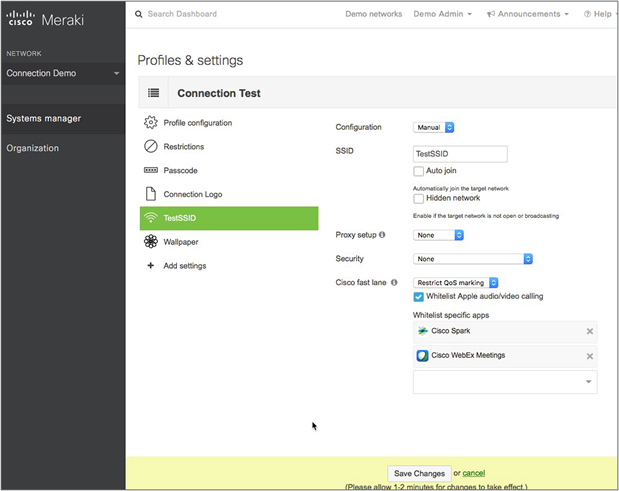
Configuring Cisco Fastlane settings and adding apps
Note: Refer to the following for general information or more information about tagging:
Cisco Meraki homepage: : https://meraki.cisco.com/products/systems-manager/
Cisco Meraki Tags and Policies: https://documentation.meraki.com/SM/Tagging
Note: Cisco Fastlane profiles are not available in the legacy version of Systems Manager. Refer to the following page for more information about upgrading to the new version of Systems Manager: https://documentation.meraki.com/zGeneral_Administration/Licensing/Systems_Manager_Licensing#Upgrading_from_Legacy_SM
Optimized enhanced distribution channel access
Cisco controllers have an EDCA profile called Fastlane. This optimized EDCA feature is derived from the latest version of EDCA in the IEEE 802.11 standard and directly benefits iOS devices connecting to Cisco infrastructure.
The previous generation of EDCA configurations, based on IEEE 802.11e-2005, allowed voice and video queues in limited time consumption. Other queues were not limited in time consumption. The updated version improves the mechanism to control the traffic queues to allow faster speeds and allocate limited time consumption values for all queues, based on the protocols enabled in the cell. With optimized EDCA enabled on the Cisco WLAN controller, iOS, iPadOS, and macOS devices and other clients connected to a Cisco infrastructure will automatically implement new 802.11 EDCA recommendations benefiting all cell devices. This provides a better environment for real voice and video traffic to be accurately prioritized while other and unmarked traffic is controlled.
Configuring optimized EDCA
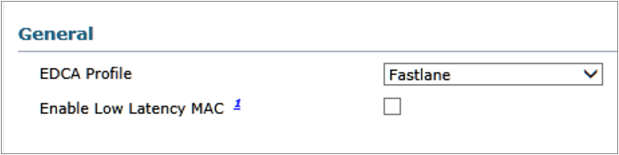
The new IEEE-802.11 EDCA parameters can be enabled by choosing the Fastlane profile for the EDCA parameter.
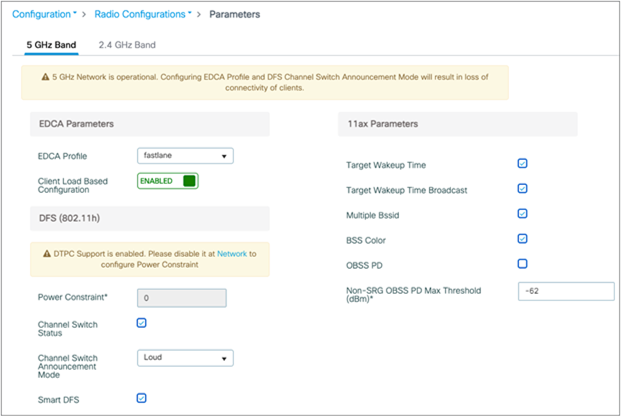
Configuring EDCA for Fastlane parameters on a Catalyst controller
On a Catalyst controller, navigate to Configuration > Radio Configurations > Parameters > [5 GHz Band or 2.4 GHz Band].
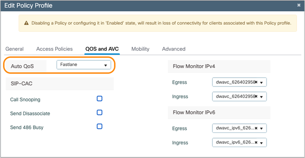
On the Catalyst controller, you also have the option to set your Auto QoS settings to Fastlane. This will set the EDCA to Fastlane and a port priority queueing to prioritize voice and Control and Provisioning of Wireless Access Points (CAPWAP).
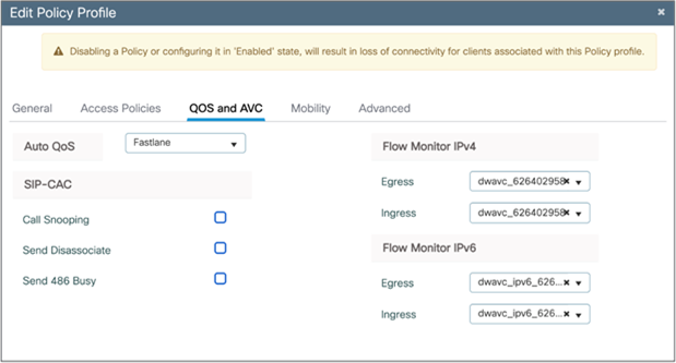
Configuring Auto QoS profile as Fastlane on a Catalyst controller
On the Catalyst controller, navigate to Configuration > Tags & Profiles > Policy > [select a policy] > QOS and AVC.
Configuring EDCA for Cisco Fastlane parameters on an AireOS controller
On an AireOS controller, navigate to Wireless > 802.11a/n/ac > EDCA Parameters to assign the Fastlane configuration to the EDCA settings.
Optimizing voice and video experience with Fastlane+
Cisco’s Fastlane+ is a co-developed solution with Apple that significantly improves the experience of any Wi-Fi 6-capable iPhone or iPad connected to a Cisco Wi-Fi 6 network. Cisco’s existing Fastlane solution has provided an enhanced user experience on iPhones and iPads with optimized roaming and QoS prioritization of VoIP applications, as well as the ordering of priority access of business-critical applications. Fastlane+ is a separate feature that builds upon this success by enhancing Wi-Fi 6’s powerful Orthogonal Frequency-Division Multiple Access (OFDMA) scheduler, enabling iOS and iPadOS 14 and above Wi-Fi-6-capable Apple devices to stream delay- and jitter-sensitive content efficiently in RF environments with high channel utilization. Together, Fastlane+ and Fastlane help ensure that users will have the best possible voice and video application experience on Apple devices when connected to a Cisco wireless network.
Note: Fastlane+ is a separate feature from the existing Fastlane solution. While the name is similar, they provide separate, nonoverlapping benefits.
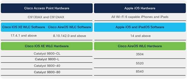
Fastlane+ software and hardware compatibility matrix
Table 3. Fastlane+ compatibility matrix
Congested networks without Fastlane+
In a Wi-Fi 6 network, multiple Wi-Fi 6 endpoints can pass traffic to the same access point in parallel, using uplink multiuser OFDMA (MU-OFDMA). Uplink MU-OFDMA dramatically increases Wi-Fi 6’s RF efficiency over previous generations of Wi-Fi by intelligently scheduling multiple endpoints’ traffic into the same AP transmission and providing parallel paths to each user. Uplink MU-OFDMA reduces network latency and maintains a great user experience well beyond the levels of previous generations of Wi-Fi. However, even Wi-Fi 6 eventually faces efficiency loss and increased latency with higher network demand, negatively impacting the end-user experience. To make intelligent and dynamic scheduling decisions, MU-OFDMA uses a Buffer Status Report (BSR) periodically through either polling or being notified automatically by the associated endpoints, which tell the AP what access category of data they plan to send next. One issue is that in a heavily loaded network, polling for these BSRs further increases the latency and load. A second issue is that the BSR’s reported traffic is already waiting in the client buffer, and therefore the sending station (STA) has not been able to transmit it yet, resulting in traffic delays. Ultimately, both of these factors together result in poor voice and video quality.
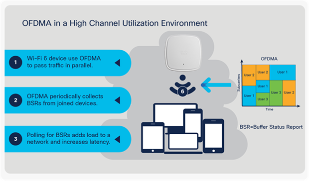
Limitations of OFDMA in a high-channel-utilization environment
How Fastlane+ solves the problem
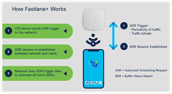
Fastlane+ solves this problem by enhancing the existing Wi-Fi 6 MU-OFDMA solution and directly cooperating with Wi-Fi 6-capable Apple endpoints running iOS and iPadOS 14 and later software. When an iOS endpoint decides to use a voice or video application, it will automatically send an Advanced Scheduling Request (ASR) trigger to the AP.
This ASR trigger:
1. Informs the AP which access category of traffic it will be sending.
2. Provides the AP with the application’s requested traffic periodicity and bit rate.
◦ Once the supported Catalyst AP receives an ASR trigger, the AP initiates an ASR session with the iOS endpoint. Using the ASR trigger’s data, the network can intelligently manage endpoint BSRs without polling. This method allows our AP to know in advance the traffic volume and pace at which the STA will send traffic, allowing it to allocate slots without having to wait for the BSR. This approach allows traffic scheduling to be more efficient, resulting in significantly reduced latency so that high-quality voice and video experiences can be maintained, even in a congested network.
How Fastlane+ prioritizes voice and video traffic
Benefits of a Fastlane+ enabled network
In a high-channel-utilization (CU) environment, a network with Fastlane+ enabled is consistently superior to one in which Fastlane+ is disabled or unsupported. Channel utilization is an indication of network load. Cisco’s engineering team ran the Fastlane+ solution through rigorous performance tests, comparing the Mean Opinion Score (MOS), packet latency, network jitter, and raw throughput with Fastlane+ both enabled and disabled in an environment with 70% to 85% channel utilization. The following are the results of these performance tests.
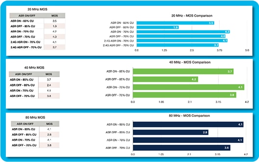
Fastlane+ enabled vs. disabled comparing MOS (Fastlane+ is referred to as ASR)
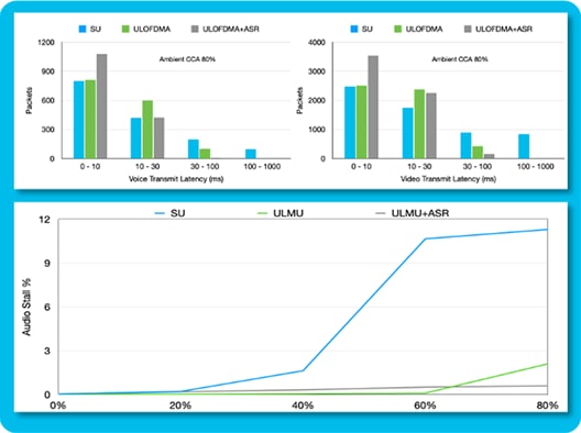
Fastlane+ enabled vs. disabled comparing latency (Fastlane+ is referred to as ASR)
As shown in the figures above, there was a significant improvement in MOS and latency when Fastlane+ was enabled versus when it was disabled. These improvements hold true regardless of the network’s bandwidth or channel width. As the channel utilization increases in the environment, so do the benefits of Fastlane+. The improvements in MOS, latency, jitter, and throughput all directly translate into a better user experience. The following table depicts those benefits.
Table 4. Benefits of a Fastlane+ enabled network
| Metrics |
Performance increase |
Benefit |
| MOS score |
40% increase |
Better voice and video quality |
| Latency |
30% decrease |
Greater reliability |
| Jitter |
10% decrease |
Greater reliability |
| Throughput |
20% increase |
High-definition streaming |
Enabling Fastlane+ on a Catalyst controller
Fastlane+ can be enabled on a Catalyst controller through either the user interface or the Command-Line Interface (CLI). It requires that ASR be enabled and that PMF (Protected Management Frame) be set to either Optional or Required.
Refer to the following for the UI navigation:
1. Navigate to Configuration > Tags & Profiles > WLANs > [Edit Existing or Add New WLAN].
2. Under the Security tab, change PMF to either Optional or Required.
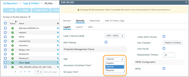
Setting the PMF option on a Catalyst controller
3. Under the Advanced tab, check the box next to Fastlane+ (ASR).
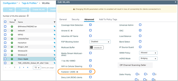
Enabling Fastlane+ on a Catalyst controller
The following are the CLI commands:
● Enable ASR
Catalyst-WLC# configure terminal
Catalyst-WLC(config)# wlan <WLAN Profile Name>
Catalyst-WLC (config-wlan)# scheduler asr
● Enable PMF
Catalyst-WLC # configure terminal
Catalyst-WLC(config) # wlan <WLAN Profile Name>
Catalyst-WLC # security pmf <optional or required>
● Display ASR and PMF status
Catalyst-WLC # show wlan id <WLAN ID>
● Display client Fastlane+ capability and latency statistics
Catalyst-WLC # show wireless client mac-address <MAC Addr> detail
Enabling Fastlane+ on an AireOS controller
Fastlane+ can be enable on an AireOS controller through the CLI. It requires ASR to be enabled and for PMF to be set to either Optional or Required.
The following are the CLI commands:
● Enable or disable ASR
AireOS-WLC# config WLAN asr {enable | disable} <WLAN ID>
● Set PMF to Optional or Required
AireOS-WLC# config wlan security pmf <optional or required>
● Display ASR and PMF status
AireOS-WLC# show WLAN <WLAN ID>
● Display client Fastlane+ capability and latency statistics
AireOS-WLC# show client asr statistics <MAC Addr>
Application visibility and control
Cisco's Application Visibility and Control (AVC) feature classifies applications using deep packet inspection techniques with the Network-Based Application Recognition (NBAR) engine and provides application-level visibility and control over Wi-Fi networks. Using AVC, the controller can detect more than 1300 applications, including voice/video, email, file sharing, gaming, and peer-to-peer applications.
AVC enables you to perform real-time analysis and create policies to reduce network congestion, costly network link usage, and infrastructure upgrades.
The recognition of business applications is supported from AVC protocol pack 6.4 and later, operating with the next-generation NBBAR (NBAR2) engine 13 and above. With this capability, you can correctly identify all applications running on iOS devices or Mac computers, subclassify how much of your traffic is data, audio, and video, and apply different policies to those.
Note: Refer to the Application Visibility and Control User Guide for more info on AVC and protocol packs: https://www.cisco.com/c/en/us/td/docs/ios/solutions_docs/avc/guide/avc-user-guide.html
After applications are recognized, the AVC feature enables you to either drop, mark, or rate-limit (by direction) the data traffic. Even if DSCP is already set, there is value in having AVC provide visibility to the traffic that it classifies. AVC integration with QoS allows you to create a policy to mark traffic using a DSCP value based on application knowledge.
When traffic from iOS devices or Mac computers reaches the wireless controller, the controller performs deep packet inspection to recognize the flow. If the flow is recognized as an application that is part of the AVC profile, the traffic is marked according to the AVC policy. For example, in situations where a wireless client sends application traffic, this traffic, upon reaching from the AP to the WLAN controller, would immediately be recognized by the NBAR2 engine and be correctly remarked according to the configured AVC profile.
Cisco Wi-Fi optimization for Apple devices
Roaming is an integral part of an enterprise wireless network. Smartphones and tablets are bound to roam from one AP to another so that they always remain connected to the Wi-Fi as the user moves. It is common for users to move while actively using a real-time app on a smartphone or tablet. As smartphones can be held close to the body (the human body limits RF signals), sudden changes to the RF signal are common for small-form-factor devices (smartphones, small tablets). By contrast, computers are larger, commonly include more than one antenna, and are held farther away from the body. Consequently, they suffer less from sudden RF changes. Providing smartphones and tablets with the ability to roam extremely fast is therefore very important, especially for real-time applications. Cisco Wi-Fi optimization for iOS mainly implies enabling IEEE standards-based 802.11r, 802.11k, and 802.11v optimizations on both the wireless infrastructure and the client devices.
Table 5. Support for roaming enhancement standards on Cisco and Apple
| Roaming enhancement |
Cisco implementation |
Apple implementation |
| 802.11r Fast Transition (FT) |
Catalyst 16.12.3 |
iOS 6 and later |
| Adaptive 802.11r |
AireOS v8.3 Catalyst 16.12.3 |
iOS 10 and later |
| 802.11k Neighbor Reporting |
Catalyst 16.12.3 |
iOS 8 and later |
| 802.11v BSS Transition Management |
Catalyst 16.12.3 |
iOS 7 and later |
Cisco and Apple recommend enabling 802.11k and 802.11v on the Cisco WLAN infrastructure. These settings support iOS, iPadOS, and macOS devices and help implement an enterprise environment configured for efficient roaming. Mac computers do not require 802.11v and 802.11k but associate transparently to WLANs where these protocols are enabled. Cisco and Apple also recommend enabling 802.11r on the Cisco WLAN infrastructure to increase the efficiency of key exchanges during roaming. However, this recommendation should be considered only for a WLAN in which all expected devices support the 802.11r roaming enhancement. Any client that does not support the roaming enhancement standards may not be able to associate with that wireless network. Enabling 802.11v and 802.11k should not have any impact on nonsupporting devices. These devices will just not benefit from the roaming enhancements brought by these two standards.
See Apple's device list to check whether your iOS, iPadOS, and macOS device supports 11r, 11k, and 11v.
In the Wi-Fi world, the Received Signal Strength Indication (RSSI) is a critical measurement of the RF signal. The RSSI value is typically shown as a negative dBm value (for example, -72 dBm). The Wi-Fi signal is considered to get stronger as the RSSI value gets closer to 0. An RSSI measurement of -65 dBm is stronger than a value of -73 dBm; therefore a client associated at -65 dBm has a better Wi-Fi signal strength than if it was connected at -73 dBm. However, this does not necessarily imply higher performance or higher throughput, as there are several other factors associated with performance.
iOS, iPadOS, and macOS devices make use of RSSI thresholds to trigger the roam scanning mechanism. This trigger threshold is the minimum signal level a client requires to maintain the current connection. iOS and iPadOS clients monitor and maintain the current Wi-Fi connection until the RSSI crosses the -70 dBm threshold. macOS clients monitor and maintain the current Wi-Fi connection until the RSSI crosses the -75 dBm threshold. Once this threshold is crossed, the client initiates a scan to find a suitable AP that it can roam to.
802.11r is an enhancement that allows for the client-AP handshake and key material exchange with the new AP to be done even before the client roams to the new AP. This method is called Fast Transition (FT). With FT, the wireless client performs just one initial authentication against the WLAN infrastructure when a connection is established to the first AP and then performs fast-secure roaming while roaming between APs of the same FT mobility domain. This eliminates much of the handshaking overhead while roaming, thus reducing the handoff times between APs while maintaining security and QoS. Since 802.11r helps reduce latency while roaming, it is useful for client devices running real-time apps such as voice and video over Wi-Fi.
Configuring 802.11r on a Catalyst controller
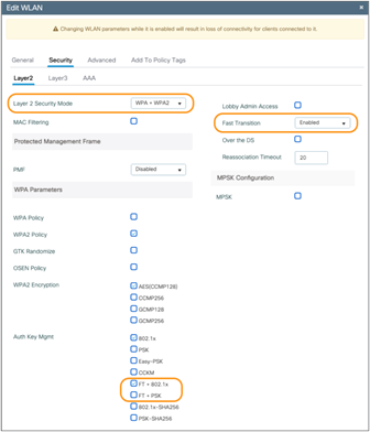
Enabling 802.11r FT on a Catalyst controller
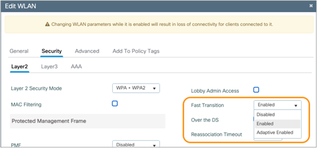
On a Catalyst controller, navigate to Configuration > Tags & Profile > WLANs > [select a WLAN] > Security > Layer2. Configure the Layer 2 Security Mode as WPA3, WPA + WPA2, or Open. Enable Fast Transition, then select either FT + 802.1x or FT + PSK, depending on the desired authentication method.
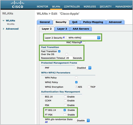
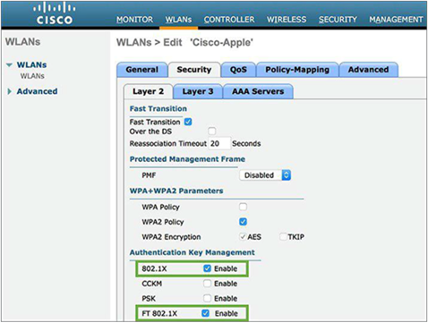
Enabling 802.11r FT on an AireOS controller
On an AireOS controller, navigate to WLANs > Security tab of the WLAN (Layer 2 Security can be WPA+WPA2 or Open). Check to enable Fast Transition. Uncheck “Over the DS” and choose FT 802.1X or FT PSK, depending on the desired security authentication method for the WLAN.
802.11r reduces the number of packets exchanged between an AP and an 11r client whose credentials are already cached. With 802.11r, the client device can establish security and QoS state prior to reassociation in two modes:
● Over the Air: Client exchanges packets directly with the new AP
● Over the Distribution System (DS): Client exchanges packets via the current AP
Unchecking “Over the DS” implies that FT uses Over the Air mode. For a high-density enterprise environment, Cisco and Apple recommend using 802.11r with Over the Air transition for optimal 11r-FT performance.
Configuring 802.11r for mixed mode
When you enable Fast Transition on the WLC, you will notice a warning pop-up saying, "Client that does not support 802.11r will be unable to join the network." This is true for clients that don't support 802.11r, as they are unaware of how to process the Fast Transition Information Elements (IEs) during authentication. Such devices will not be able to see or join an 802.11r-enabled WLAN.
This issue led to the development of mixed mode, which allows both non-FT and FT versions of authentication modes to be enabled on the same WLAN. This mixed-mode support eliminates the need to create a separate SSID for 802.11r-enabled devices.
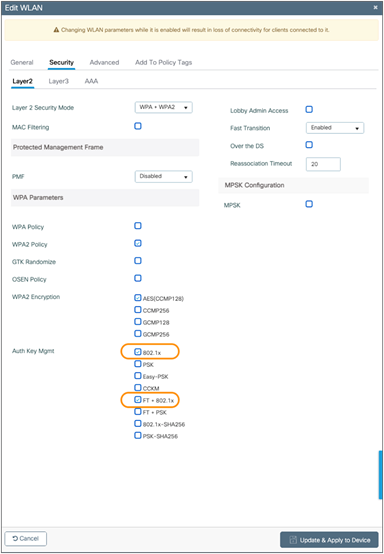
Enabling 802.11r mixed mode on a Catalyst controller
On a Catalyst controller, navigate to Configuration > Tags & Profiles > WLANs > [select WLAN] > Security > Layer2 and check both FT and non-FT authentication. For example, check 802.1X and FT + 802.1X, or PSK and FT + PSK.
Enabling 802.11r mixed mode on an AireOS controller
On an AireOS controller, navigate to WLANs > Security tab of the WLAN and check both FT and non-FT authentication. For example, check 802.1X and FT 802.1X, or PSK and FT-PSK.
Non-802.11r clients that have the updated wireless LAN drivers for 802.11r compatibility can join this 802.11r mixed-mode WLAN. Clients with newer wireless LAN chipsets and clients with updated chipset drivers with 802.11r compatibility may all be able to use the 802.11r mixed-mode SSID configuration. For example, Apple introduced the 11r-compatibility drivers for MacBook notebook computers running OS X Mavericks v10.9, which allowed the MacBook to correctly identify and associate to a mixed-mode SSID (for example, FT-PSK + PSK). Any MacBook running an older version of macOS (even with the same chipset) might be able to see the 11r mixed-mode SSID but may fail to associate to it.
Note: Cisco and Apple recommend performing lab tests for an 11r mixed-mode WLAN before enabling it on the network. You can avoid unexpected behavior by using a newly created WLAN with mixed mode enabled. If you try to edit a previously known WLAN from regular mode or FT-only mode to mixed mode, you may see an unexpected result in which the 11r-compatible clients (such as MacBooks) are still not able to associate, as they might be using the cached information from its previous association. If you do choose to edit a known Wi-Fi network's configuration from regular mode to mixed mode, the workaround is to make the 11r-compatible clients "forget" that wireless network and then try rejoining it.
It is recommended that you check multiple vendor devices to ensure that the 11r compatibility driver is present before using the mixed-mode SSID. If you cannot predict what clients will try to join your 802.11r-enabled WLAN, then creating a separate SSID for non-802.11r clients is advisable. Please note that 11r compatibility does not mean that those devices are 802.11r enabled. It simply means that they can correctly identify and associate to a mixed-mode SSID.
The configuration is sent to all devices, but the adaptive 802.11r feature will be applied only to supporting iOS and iPadOS devices. All other devices will be able to associate using standard Wi-Fi Protected Access 2 (WPA2) (including macOS devices).
Adaptive 802.11r is an enhancement feature specifically designed for iOS and iPadOS devices associating with a Cisco WLAN infrastructure to optimize the speed of key negotiation during roaming events in encrypted (WPA2) WLANs. All iOS and iPadOS devices, upon associating to the Cisco AP, will automatically implement 802.11r, even when 11r is not openly enabled on the wireless network configuration.
Note: Refer to the following page for Apple devices that support adaptive 802.11r: https://support.apple.com/en-us/HT202628
Enabling adaptive 802.11r on the WLAN for a Catalyst controller
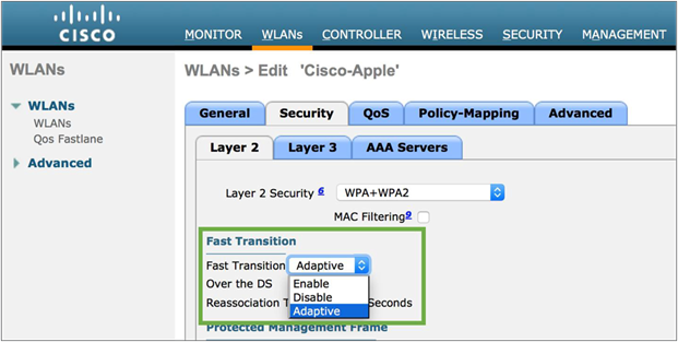
Enabling adaptive 802.11r on the WLAN for an AireOS controller
Once adaptive 802.11r is enabled on the WLAN, the AP provides the information in the beacons. In an association request from iOS or iPadOS devices, 802.11r is automatically requested, as the device is aware of the adaptive 802.11r configuration before it even initiates the association request. The AP then provides the association response confirming 802.11r by mentioning the domain and Fast Transition (802.11r) parameters.
802.11k Radio measurement and neighbor reporting
The 802.11k standard allows clients to request reports containing information about known neighbor APs that are candidates for roaming. The request is in the form of an 802.11 management frame known as an action frame. The AP responds with a list of neighbor APs on the same WLAN and their Wi-Fi channel numbers. The AP response is also an action frame. With the 802.11k response frame coming from the AP, the client becomes aware of the best channel candidates that should be scanned before the next roam. Having this handy neighbor list allows the client to strategically probe these reported channels first when approaching the next roaming opportunity, thus reducing its scanning time and expeditiously deciding which AP it should roam to. This feature is especially useful for clients with high mobility and constrained battery resources, such as smartphones and tablets.
On Cisco infrastructure, the 802.11k algorithm uses RRM to determine neighbors of the AP to which the client is associated, and to check which APs heard the client. The AP then returns a list of the six best APs to the client. With the neighbor list information, the 11k-capable client does not need to scan all channels to find which APs it can roam to. Not having to scan all the channels also reduces channel utilization, thereby potentially saving airtime on the channels. Additionally, the battery life of iOS and iPadOS devices is benefited, since the devices are not frequently changing the radio configuration to scan each channel or send probe requests on each channel.
This approach prevents the device from having to process all the probe response frames. It also reduces interruption of connectivity due to off-channel passive scanning through listening for beacons.
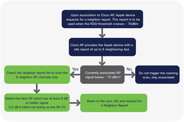
Neighbor report processing flow for iOS devices supporting 802.11k
Using 802.11k to discover and figure out which AP the device should potentially roam (associate) to is only part of the process. After this, iOS devices also need to swiftly complete the authentication process so that users experience minimal disruption in service. In this process, iOS and iPadOS devices authenticate with the new AP and deauthenticate from the current AP. Enabling 802.11r and 802.11k on the WLAN together is a good way to quicken the roaming process. Doing so will allow iOS and iPadOS devices not only to reduce scan times but also to preauthenticate against the potential APs, thus reducing authentication time and allowing the devices to briskly complete the roam to the new AP.
Configuring 802.11k on a Cisco controller
Enabling neighbor reporting on the WLAN on a Catalyst controller
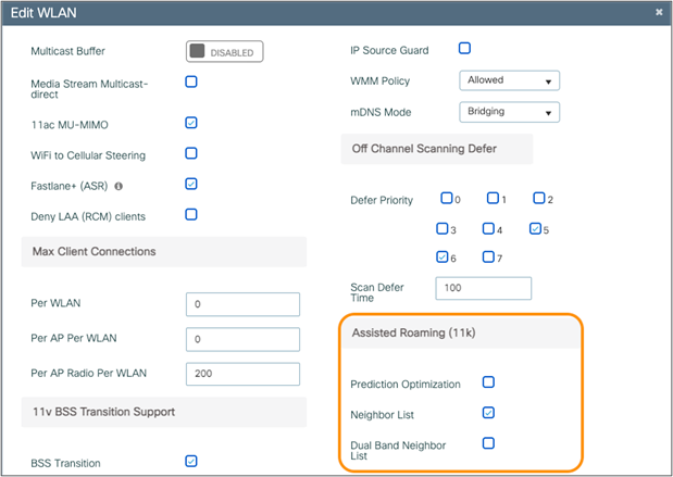
For Catalyst controllers, navigate to Configuration > Tags & Profiles > WLAN > [Edit or Add WLAN] > Advanced > [scroll down to the 11k section] > [check the Neighbor List box to enable 802.11k neighbor reporting].
Enabling neighbor reporting on the WLAN on an AireOS controller
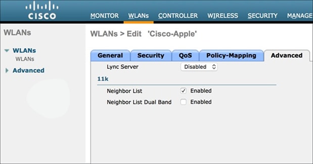
For an AireOS controller, navigate to WLANs > Advanced > [scroll down to the 11k section] > [check the Neighbor List box to enable 802.11k neighbor reporting].
802.11v Basic Service Set (BSS) Transition Management
802.11v Basic Service Set (BSS) Transition Management is part of the Wireless Network Management (WNM) feature, which acts as a platform for the clients and the infrastructure to potentially exchange operational information so that both sides have additional awareness of the WLAN conditions.
802.11v offers a network-assisted roaming enhancement for client devices, in which the AP will try to assist in the roaming decision-making by providing an unsolicited recommendation in the form of a request to the client. This request will contain a suggestion for the best available AP that the client could potentially roam to. Client devices and infrastructure may both use WNM to exchange operational information to gain additional awareness of the WLAN conditions. Although the client always has the freedom to choose whether to accept or reject the advice offered by the AP, the additional awareness can assist in building a firm foundation for self-correcting events and actions to be implemented. This feature is especially useful for clients with high mobility, such as smartphones and tablets.
802.11v BSS Transition Management functions with three sets of frames:
● BSS Transition Management Query: Transmitted from a client to the AP
● BSS Transition Management Request: Transmitted from the AP to the client
● BSS Transition Management Response: Transmitted from a client to the AP, but only following a BSS Transition Management Request
iOS and iPadOS devices supporting 802.11v can respond to the BSS Transition Management Query from the AP and use the provided list of preferred APs to make roaming decisions. Note that this preferred list of APs could be different from the neighbor AP list acquired with the 802.11k exchange. Unlike 802.11k, where the iOS and iPadOS device will request a neighbor list only upon association or reassociation, BSS Transition Management queries and requests can be sent out at any time. For example, a client can send a query in a solicited way asking for a recommendation for a good AP to roam to, or an AP can offer an unsolicited request to the client asking it to roam to a particular AP if the client is experiencing bad connectivity. A BSS Transition Management Request from an AP can also be triggered for other reasons, including a load-balancing event. Accepting or rejecting these requests is the primary function of the BSS Transition Management Response. The client can also include a reason code for acceptance or rejection.
Configuring 802.11v on a Cisco controller
Enabling 802.11v BSS Transition Management on a Catalyst controller
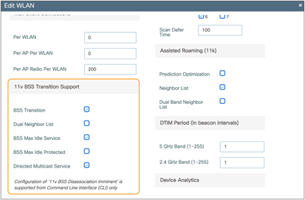
For Catalyst controllers, navigate to Configuration > Tags & Profiles > WLAN > [Edit or Add WLAN] > Advanced > [scroll down to the 11v section] > [check BSS Transition to enable 11v BSS Transition Management support].
Enabling 802.11v BSS Transition Management on an AireOS controller
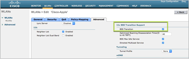
For AireOS controllers, navigate to WLANs > Advanced tab of the WLAN and scroll down to the 11v section. Check BSS Transition to enable BSS Transition Management support.
The disassociation imminent is an optional add-on for the BSS Transition Support feature. It is used to inform the client that it will be disconnected from the AP after the time indicated in the Disassociation Timer field. The Disassociation Timer is expressed in the number of beacon intervals. Once the Disassociation Timer reaches zero, the AP can forcefully disassociate the client at any time.
Bonjour is a zero-configuration networking protocol that locates devices such as printers, other computers, and the services that those devices offer on a local network using multicast DNS (mDNS) service records.
The Bonjour protocol operates on service announcements and service queries that allow devices to ask and advertise specific applications, such as:
● Printing services
● File-sharing services
● Remote desktop services
● iTunes file sharing
● iTunes wireless iOS device syncing
● AirPlay
Each query or advertisement is sent to the Bonjour multicast address for delivery to all clients on the subnet. Apple's Bonjour protocol relies on mDNS operating at UDP port 5353 and sends to the reserved group addresses.
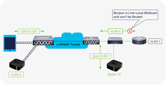
Bonjour services for Apple TV on Cisco WLAN
Note: Refer to Cisco's Bonjour page for details: https://www.cisco.com/c/en/us/solutions/enterprise-networks/dna-service-bonjour.html#~stickynav=4
Knowing your wireless environment
In addition to designing your Cisco WLAN around the best practices for iOS, iPadOS, and macOS devices, network maintenance and monitoring help to keep track of overall network health. The application and roaming performance for iOS, iPadOS, and macOS devices is largely dependent on AP coverage and Wi-Fi channel bandwidth. Cisco's controller user interface provides relevant data to granularly track important statistics for the APs and the RF environment.
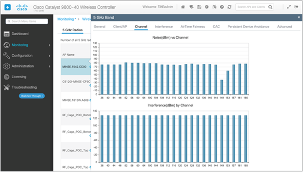
Checking AP statistics to monitor the RF environment for a Catalyst controller
For Catalyst controllers, navigate to Monitoring > Wireless > Radio Statistics > [select Channel tab] > [select AP] > [select tab you want to view].
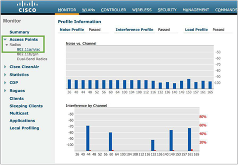
Checking AP statistics to monitor the RF environment for an AireOS controller
For AireOS controllers, navigate to Monitor > Access Points > Radios > 802.11a/n/ac/ax and click the radio button on the right side. Then select details to access statistics such as noise profile, interference, and coverage.
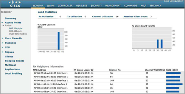
The data includes the Wi-Fi channel number, interference on that channel (red), current channel load statistics (blue), number of VoIP calls, and other client-related information such as client count vs. RSSI and client count vs. SNR. Using this information, users can get insight into the data rate capabilities of iOS, iPadOS, and macOS devices and what data rates might be in actual use because of RSSI and SNR for the associated clients.
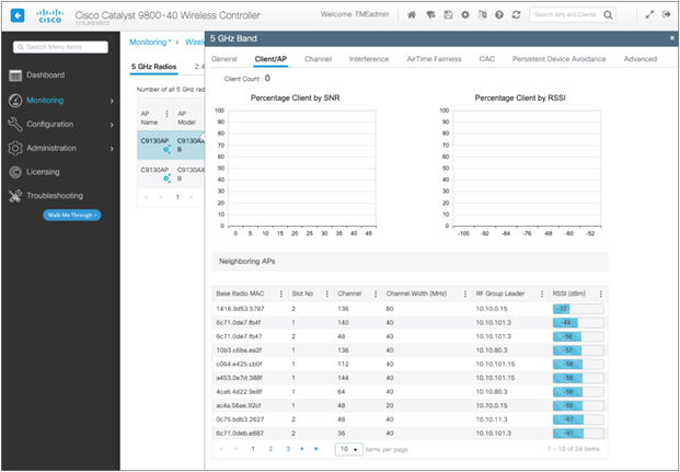
Monitoring for client count against RSSI/SNR and AP neighbors’ RSSI for a Catalyst controller
Monitoring for client count against RSSI/SNR and AP neighbors’ RSSI for an AireOS controller
The information about the clients in the Rx Neighbors Information section can be used to get a quick understanding of how much coverage overlap there is between the APs that neighbor the AP with which an iOS, iPadOS, or macOS device is associated.
Peer-to-peer activity monitoring
Besides RF channel layout, planning, and associated enterprise wireless network design, another factor to consider is the role and potential impact of newer iOS devices and Mac computers and their peer-to-peer behavior in your enterprise network. A peer-to-peer methodology for AirPlay enables compatible devices to establish direct wireless communication with an Apple TV using AirPlay. This feature is enabled by default on compatible devices and is the preferred data path for devices regardless of the availability of an established network connection.
This peer-to-peer capability between compatible Apple TVs and other Apple endpoints is possible even if the respective devices are on different wireless networks or if there is no network connectivity whatsoever. The connection is accomplished using a variety of methods, such as Bluetooth Low Energy (BLE) for the initial discovery of an available Apple TV. Thereafter a direct communication path using an 802.11 channel is established between the two peer devices (the AirPlay sender and AirPlay receiver). As such, this activity can affect either channels 149+1 or 153-1 (channels 36 and 44 in some countries) when a peer-to-peer AirPlay connection involving a compatible Apple TV is in use. If peer-to-peer AirPlay is not supported on either the AirPlay sender or receiver, the established network infrastructure connection is used instead for AirPlay communication.
When a compatible iOS, iPadOS, or macOS device has discovered a third-generation Rev A or later Apple TV using its Bluetooth adapter, and all involved endpoints support peer-to-peer AirPlay functionality, the next phase of the associated discovery process will lead the compatible Apple end device and the Apple TV to communicate directly in a peer-to-peer fashion using 802.11 channel 149+1 in the 5-GHz band. Note that when using an Apple TV Rev 4 (2015), channels 149 to 161 can be used for the peer-to-peer communication. However, as with 802.11ac and 802.11ax, the channel width is dynamically determined per frame, so channel width may be 40 MHz or even 20 MHz.
After the discovery phase is completed, the end user can select the applicable Apple TV to start AirPlay communication. This causes the 802.11 radios to timeshare or balance between channel 149+1 for AirPlay and the infrastructure wireless channel used for the active connection to the wireless network infrastructure. If neither device is currently connected to the wireless network, the devices will use channel 149+1 for AirPlay functionality. Wireless peer-to-peer AirPlay communications adhere to 802.11 standards.
AirDrop is an Apple feature that is used to share content between iOS, iPadOS, and macOS devices using peer-to-peer communication over Wi-Fi. Like AirPlay, AirDrop uses 802.11 channel 149+1 or 153-1 in the 5-GHz band to transfer content between devices. During AirDrop activity, the devices time-slice the Wi-Fi connectivity and content sharing by jumping back and forth between the Wi-Fi connectivity with the associated AP and the peer-to-peer connectivity to complete the transfer of the content.
Cisco recommends monitoring the UNII-3 band for high channel utilization with regard to peer-to-peer activity against regular Wi-Fi activity. If a lot of iOS, iPadOS, or macOS devices are expected to use continuous peer-to-peer connections daily, a potential solution would be to remove channels 149 and 153 from the DCA list to avoid congestion. Cisco strongly recommends channel exclusion with the use of RF profiles to effectively apply the removal of the channels to only the affected APs, and not globally across all APs.
Note: Refer to the guidelines in the Enterprise Mobility Design Guide for more details on how to configure DCA: http://www.cisco.com/c/en/us/td/docs/wireless/controller/8-1/Enterprise-Mobility-8-1-Design- Guide/Enterprise_Mobility_8-1_Deployment_Guide.pdf.
The Apple Watch is another portable device that uses peer-to-peer communication to function. It supports both Bluetooth and Wi-Fi connections for communicating with the paired iOS device. Although there are two modes of communication, the primary mode of connectivity is Bluetooth to transfer data back and forth between the Apple Watch and iPhone. If Bluetooth is off, the watch switches to Wi-Fi to stay connected to the paired iPhone. Currently, the Apple Watch supports only 802.11b/g/n in the 2.4-GHz band, with open or pre-shared key security authentication.
The Apple Watch can also use tetherless Wi-Fi to connect to the internet independently. It means that even without the iPhone, the Apple Watch will be able to connect to the Wi-Fi network. Since the Apple Watch is 2.4 GHz only, there should not be any impact on the 5-GHz networks, even if more than one Apple Watch is communicating with the Wi-Fi network. Note: This doesn’t apply to Apple Watch 6 and 7, which are dual band.
Summary rule table for configuration audit
The following are the best practices, from a controller configuration perspective, for any wireless deployment:
Prioritize the 5-GHz band
● Make sure the configured SSID is not on 5 GHz only.
● Check whether the 5-GHz network is disabled.
● Check whether there is a low percentage of clients in 5 GHz.
Radio frequency
● Check whether channel utilization is lower than 30% and interference is lower than 20%.
● Check for a warning if more than 10% of all clients have low SNR (< 25 dB).
● Check for a warning on isolated APs (no neighbors at RSSI -70 dBm or higher).
● Check whether any APs have more than four DFS events per day.
● Check whether more than 10% of APs have high co-channel interference. If so, recommend reducing channel width to 20 MHz.
● Use 40-MHz bandwidth and check that the best maximum size is 40.
● Data rates: 12 Mbps enabled and 24 Mbps as mandatory. All modulation and coding scheme (MCS) rates should be enabled.
Authentication checks
● 5-GHz SSID should use 802.1X authentication whenever applicable.
QoS checks
● Make sure you are using 17.4.1/8.10.141.0 or higher for Fastlane+ on Wi-Fi 6 APs.
● If the version is lower, make sure that at least Fastlane is being configured.
● Use Upgrade Advisor for a recommendation on which higher version to use with Fastlane+.
● Fastlane+ requires that PMF (Optional or Required) and ASR be enabled.
● WLAN QoS must be set to Platinum.
● The EDCA profile must be Fastlane enabled.
● Ensure that the Platinum UDP limitation is set to zero.
● Ensure that DCSP is trusted upstream.
● Ensure that Fastlane is enabled on the WLAN.
● It’s recommended that AUTOQOS-AVC-PROFILE QoS be in use in the WLAN.
WLAN checks
● Ensure that 802.11k (neighbor list) and 802.11v (BSS Transition, BSS max idle, Directed Multicast Service [DMS]) are all enabled.
● Disable the FT Over the DS setting.
● Set FT to adaptive.
● Configure WMM as required.
To configure AP-side warning and trap notifications on a Catalyst controller, navigate to Configuration > Radio Configurations > RRM > [select a band] > General.
Configuring the thresholds in the Profile Thresholds for Traps section will allow the controller to activate warnings when the threshold is not met. These include Interference Percentage, Clients, Noise, Utilization Percentage, and Throughput.
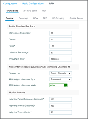
Configuring warning and trap notifications
To configure client-side warning and trap notifications on a Catalyst controller, navigate to Configuration > Radio Configurations > RRM > [select a band] > Coverage.
Configuring thresholds will allow the controller to activate warnings when the threshold is not met. These include Data RSSI, Voice RSSI, Minimum Failed Client per AP, etc.
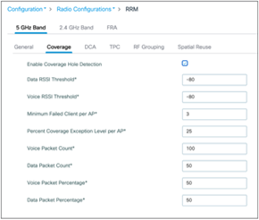
Note: For 802.11 retransmission, no additional alarms or trap configuration is required. The threshold is preconfigured and will activate when there is excessive retransmission.
iOS, iPadOS, and macOS devices on Cisco WLAN best practices summary
Recommendations for iOS devices and Mac computers on Cisco WLAN are summarized as follows:
● Cisco recommends a 5-GHz-only network and coverage design for all iOS, iPadOS, and macOS devices. The 5-GHz band is typically less affected by non-802.11 sources of interference than the
2.4-GHz band.
● Cisco recommends closely monitoring the channel utilization provided through the WLC dashboard. High channel utilization values may be an indication of new sources of interference, AP outages, or an influx of new Wi-Fi devices.
● Cisco recommends monitoring for APs that are changing channels frequently and taking action to resolve identified 5-GHz Wi-Fi channels that are most affected by known sources of interference on a regular basis.
● Cisco recommends that all iOS, iPadOS, and macOS devices be connected to a WLAN with a QoS value of Platinum (voice) and with WMM set to Required. This allows the Ethernet traffic from the AP to connect to the switch port with a QoS value representative of the priority on the Wi-Fi channel.
● Cisco and Apple recommend that you configure an 802.11r mixed-mode WLAN for Fast Transition 802.1X-capable clients (WPA2 PSK-only clients are not recommended) and 802.11r-compatible clients to join the same network. In networks with a large proportion of recent iOS clients and some non-802.11r clients, adaptive 11r may provide similar performance while offering better compatibility between iOS and non-802.11r clients.
● For high-density enterprise environments, Cisco and Apple recommend using 802.11r with Over the Air FT for optimal 802.11r FT performance. For environments with large cells, 802.11r with Over the DS may reduce the number of packets dropped by clients at the edge of the cell.
● Cisco recommends configuring 802.11r adaptive mode for controllers.
● Cisco recommends configuring 802.11k on the WLAN to provide iOS devices with a neighbor list response.
● Cisco and Apple recommend the use of 802.11v BSS Transition Management to help balance iOS client load across access points.
● Cisco recommends managing data rates to provide the coverage that is suitable for the number of clients needed in the coverage of a channel, with the bandwidth needed in the coverage of the channel.
● For channel bonding, Cisco recommends using 20 MHz when channel density (such as a high number of APs in the environment) is needed and considering 40 MHz when client traffic uses heavy bandwidth (such as video) and DFS channels are available.
● Cisco recommends using DSCP 46 for voice traffic-based applications, which translates to 802.11e UP 6.
● Cisco and Apple recommend a minimum data rate of 12 Mbps and 24 Mbps as the mandatory rate as a general best practice for iOS devices and Mac computers on a Cisco WLAN. If the 5-GHz coverage is marginal, set 6 Mbps as the lowest mandatory rate, and make sure that 12 and 24 Mbps are enabled as well.
● Cisco highly recommends leaving all MCS (802.11n, 802.11ac, 802.11ax) rates enabled.
● Cisco always recommends that Apple devices observe a minimum of two APs with an RSSI measurement of -67 dBm or better. Mac computers can also perform optimally when observing a minimum of two APs with an RSSI measurement of -72 dBm or better.
● Cisco recommends monitoring for peer-to-peer communication activity on UNII-3 band channels in an environment with high client density. If a high number of iOS, iPadOS, macOS, or tvOS (Apple TV) devices are expected to perform peer-to-peer activity, excluding channels 149 and 153 from DCA can be considered as a last-resort measure. Note: Wi-Fi channels 149 to 153 are frequently used for AirPlay.
● Apple recommends upgrading all Apple devices to the most recent version of iOS and macOS.
● RF design and monitoring recommendation summary:
◦ Overall channel utilization should be less than 40%.
◦ A minimum SNR of 25 dB.
◦ 802.11 retransmissions should be kept under 15%.
◦ Packet loss should remain under 1 percent, and jitter should be kept to less than 100 ms.
The best practice for WLANs also includes deploying highly available WLCs, in conjunction with a high density of access points, to promote always-available WLAN infrastructure. In addition, Cisco's High Density Experience (HDX) suite of technologies, such as Cisco CleanAir®, Optimized Roaming, and RRM, automatically allows you to optimize your network performance while simultaneously reducing coverage holes and bypassing interference.
Fastlane+ video overview and demo
https://youtu.be/uYlHpgZ6XTM
Fastlane+ frequently asked questions https://www.cisco.com/c/dam/en/us/td/docs/wireless/access_point/9130ax/tech-notes/fastlane-faq.pdf
Fastlane+ white paper
https://www.cisco.com/c/en/us/solutions/collateral/enterprise-networks/white-paper-c11-744739.html
Cisco AireOS Wireless LAN Controller deployment guides
https://www.cisco.com/c/en/us/support/wireless/wireless-lan-controller-software/products-installation-and-configuration-guides-list.html
Detailed overview on how 802.11r works on Cisco WLAN https://www.cisco.com/c/en/us/support/docs/wireless-mobility/wireless-lan-wlan/116493-technote-technology-00.html#anc24
Cisco Device Classification Guide
https://www.cisco.com/c/en/us/td/docs/wireless/controller/technotes/8-0/device_classification_guide.html
Cisco Application Visibility and Control Q & A
https://www.cisco.com/c/en/us/products/collateral/wireless/8500-series-wireless-controllers/qa_c67-722538.html
Configuring Application Visibility and Control https://www.cisco.com/c/en/us/td/docs/wireless/controller/technotes/8-8/AVC_8point8_dg.html
Wi-Fi network roaming with 802.11k, 802.11r, and 802.11v on iOS
https://support.apple.com/en-us/HT203068
iOS Deployment Reference
https://help.apple.com/deployment/ios/
VoIP Best Practices Guide for iOS https://developer.apple.com/library/ios/documentation/Performance/Conceptual/EnergyGuide- iOS/OptimizeVoIP.html
IEEE 802.11r/k/v standards
https://ieeexplore.ieee.org/servlet/opac?punumber=4544752
https://ieeexplore.ieee.org/xpl/mostRecentIssue.jsp?punumber=4573290
https://ieeexplore.ieee.org/xpl/articleDetails.jsp?arnumber=5716530
AirPlay Technical Guide
https://support.apple.com/guide/deployment/use-airplay-dep9151c4ace/1/web/1.0